JP2014139072A - Wiper arm followed by pantograph type kinetic action - Google Patents
Wiper arm followed by pantograph type kinetic action Download PDFInfo
- Publication number
- JP2014139072A JP2014139072A JP2013260028A JP2013260028A JP2014139072A JP 2014139072 A JP2014139072 A JP 2014139072A JP 2013260028 A JP2013260028 A JP 2013260028A JP 2013260028 A JP2013260028 A JP 2013260028A JP 2014139072 A JP2014139072 A JP 2014139072A
- Authority
- JP
- Japan
- Prior art keywords
- rod
- wiper arm
- arm
- wiped
- sub
- Prior art date
- Legal status (The legal status is an assumption and is not a legal conclusion. Google has not performed a legal analysis and makes no representation as to the accuracy of the status listed.)
- Granted
Links
- 238000011144 upstream manufacturing Methods 0.000 claims description 6
- 229910052782 aluminium Inorganic materials 0.000 claims description 2
- XAGFODPZIPBFFR-UHFFFAOYSA-N aluminium Chemical compound [Al] XAGFODPZIPBFFR-UHFFFAOYSA-N 0.000 claims description 2
- 229910052751 metal Inorganic materials 0.000 claims description 2
- 239000002184 metal Substances 0.000 claims description 2
- 238000000034 method Methods 0.000 claims description 2
- FYYHWMGAXLPEAU-UHFFFAOYSA-N Magnesium Chemical compound [Mg] FYYHWMGAXLPEAU-UHFFFAOYSA-N 0.000 claims 1
- 239000000956 alloy Substances 0.000 claims 1
- 229910045601 alloy Inorganic materials 0.000 claims 1
- 229910052749 magnesium Inorganic materials 0.000 claims 1
- 239000011777 magnesium Substances 0.000 claims 1
- 230000000694 effects Effects 0.000 description 6
- 230000001133 acceleration Effects 0.000 description 2
- 230000006837 decompression Effects 0.000 description 2
- 238000006073 displacement reaction Methods 0.000 description 2
- 239000007788 liquid Substances 0.000 description 2
- 239000007787 solid Substances 0.000 description 2
- 229910000861 Mg alloy Inorganic materials 0.000 description 1
- 238000004140 cleaning Methods 0.000 description 1
- 239000002131 composite material Substances 0.000 description 1
- 238000010586 diagram Methods 0.000 description 1
- 238000001746 injection moulding Methods 0.000 description 1
- 238000000465 moulding Methods 0.000 description 1
Images


Classifications
-
- B—PERFORMING OPERATIONS; TRANSPORTING
- B60—VEHICLES IN GENERAL
- B60S—SERVICING, CLEANING, REPAIRING, SUPPORTING, LIFTING, OR MANOEUVRING OF VEHICLES, NOT OTHERWISE PROVIDED FOR
- B60S1/00—Cleaning of vehicles
- B60S1/02—Cleaning windscreens, windows or optical devices
- B60S1/04—Wipers or the like, e.g. scrapers
- B60S1/32—Wipers or the like, e.g. scrapers characterised by constructional features of wiper blade arms or blades
- B60S1/34—Wiper arms; Mountings therefor
- B60S1/3402—Wiper arms; Mountings therefor with means for obtaining particular wiping patterns
- B60S1/3409—Wiper arms; Mountings therefor with means for obtaining particular wiping patterns the wiper arms consisting of two or more articulated elements
-
- B—PERFORMING OPERATIONS; TRANSPORTING
- B60—VEHICLES IN GENERAL
- B60S—SERVICING, CLEANING, REPAIRING, SUPPORTING, LIFTING, OR MANOEUVRING OF VEHICLES, NOT OTHERWISE PROVIDED FOR
- B60S1/00—Cleaning of vehicles
- B60S1/02—Cleaning windscreens, windows or optical devices
- B60S1/04—Wipers or the like, e.g. scrapers
- B60S1/32—Wipers or the like, e.g. scrapers characterised by constructional features of wiper blade arms or blades
- B60S1/34—Wiper arms; Mountings therefor
- B60S1/3402—Wiper arms; Mountings therefor with means for obtaining particular wiping patterns
- B60S1/3406—Wiper arms; Mountings therefor with means for obtaining particular wiping patterns the wiper blades being rotated with respect to the wiper arms around an axis perpendicular to the wiped field
-
- B—PERFORMING OPERATIONS; TRANSPORTING
- B60—VEHICLES IN GENERAL
- B60S—SERVICING, CLEANING, REPAIRING, SUPPORTING, LIFTING, OR MANOEUVRING OF VEHICLES, NOT OTHERWISE PROVIDED FOR
- B60S1/00—Cleaning of vehicles
- B60S1/02—Cleaning windscreens, windows or optical devices
- B60S1/04—Wipers or the like, e.g. scrapers
- B60S1/32—Wipers or the like, e.g. scrapers characterised by constructional features of wiper blade arms or blades
- B60S1/38—Wiper blades
- B60S1/3806—Means, or measures taken, for influencing the aerodynamic quality of the wiper blades
Landscapes
- Engineering & Computer Science (AREA)
- Mechanical Engineering (AREA)
- Current-Collector Devices For Electrically Propelled Vehicles (AREA)
- Cleaning In General (AREA)
Abstract
Description
本発明の主題は、パンタグラフ式の動的作用を伴うワイパーアームである。 The subject of the present invention is a wiper arm with a pantograph-type dynamic action.
本発明は、特に(これに限定されるものではないが)パノラマ型フロントガラスを有した自動車両に備え付けられるように企図されている。 The present invention is specifically intended to be included in (but not limited to) a motor vehicle having a panoramic windshield.
パノラマ型フロントガラスは一般的に、中央部分などの小さい曲率の部分と、端部に位置する部分などの大きい曲率の部分とを備えていることが知られている。従って、パノラマ型フロントガラスは、ワイパーの経路がフロントガラスの全面に渡って円形である従来のフロントガラス用ワイパーを用いては、効果的に払拭することができない。 It is known that a panoramic windshield generally includes a portion having a small curvature such as a central portion and a portion having a large curvature such as a portion located at an end portion. Therefore, the panoramic windshield cannot be wiped off effectively using a conventional windshield wiper in which the path of the wiper is circular over the entire surface of the windshield.
パンタグラフ式のフロントガラス用ワイパーは、パノラマ型フロントガラスの全ての部分にアクセスすることによって払拭の有効性を最適化する。それは、フロントガラスの少なくとも一定の部分(これらは特に、端部に位置するこれらの部分を含む)に渡ってフロントガラス用ワイパーに非円形の経路を与えることのできる、その特別な構造や特別な動的作用のおかげである。このタイプのフロントガラス用ワイパーは一般的に、停止位置において互いに略平行で略同じ平面内を延びる2本のロッドを備えたアームと、概してこのアームに対して回動可能に取り付けられたワイパー部(払拭体)とを具備している。従来のフロントガラス用ワイパーの場合と同様に、2本ではなく1本のアームしか存在しないという事実が費用の節約をもたらしてもいる。 Pantograph windscreen wipers optimize wiping effectiveness by accessing all parts of the panoramic windscreen. It has a special structure and special ability to give a windshield wiper a non-circular path over at least certain parts of the windscreen, especially including these parts located at the edges Thanks to the dynamic action. This type of windscreen wiper is typically an arm with two rods that are substantially parallel to each other and extend in substantially the same plane at a stop position, and a wiper portion that is generally pivotably attached to the arm. (Wiping body). As with conventional windscreen wipers, the fact that there is only one arm instead of two has also saved money.
具体的には、例として図1Aおよび図1Bに示すように、パンタグラフ式のフロントガラス用ワイパーは一般的に、主ロッド2aおよび副ロッド2bを備えたアーム1を具備しており、それらのロッド2a,2bが、停止位置において互いに略平行に長手方向へ延びると共に、少なくとも部分的に略同じ平面内を延びている。
Specifically, as shown in FIG. 1A and FIG. 1B as an example, a pantograph windshield wiper generally includes an
アーム1は、その長手方向の一端部の所に、少なくとも1つの回動軸3を備えている。その回動軸3は、おおよそ被清掃表面によって規定される平面に対して略垂直な軸線の周りを、そのアーム1が概して回動できるようにしている。
The
特にこの場合、主ロッド2aはスリーブ6によって、この長手方向端部に連結されている。
Particularly in this case, the
その長手方向の他端部の所で、アーム1は、少なくとも1つの連結要素4を備えている。その連結要素4は、一方では2本のロッド2a,2b同士が互いに結合されるのを可能とし、他方ではワイパー部(図示せず)が連結されるのを可能とする。この連結要素4は、2つの円筒状スリーブ5a,5bを介してロッド2a,2bに取り付けられている。それらのスリーブ5a,5bは、前記ロッド2a,2bの一端部がその中に導入され得るように構成されている。副ロッド2bは、一方ではスリーブ5bを介して前記連結要素4に連結され、他方では上述したタイプの円筒状スリーブ9によって、アーム1における前記回動軸3を備えた長手方向端部に連結されている。
At its other longitudinal end, the
代替的な形態においては、スリーブ5aおよび6と、主ロッド2aとが一部品として作られる。更に、スリーブ5bおよび9と、副ロッド2bとが、同じく一部品として作られてもよい。
In an alternative form, the
電気モータ(図示せず)によって、アーム1を回動させて往復払拭動作を生じさせることができる。
The
にもかかわらず、これらのパンタグラフ式のフロントガラス用ワイパーは、それらの払拭の有効性に影響を与える空力性能が不十分であるという欠点を有している。それは特に、前記アームがフロントガラスに対して、十分にしっかりとは押し付けられないからである。 Nevertheless, these pantograph windshield wipers have the disadvantage of insufficient aerodynamic performance that affects their wiping effectiveness. This is especially because the arm cannot be pressed sufficiently firmly against the windshield.
本発明の重要な目的は、空力性能を改善するような手法で構成されたパンタグラフ式のワイパーアームを提案することによって、この大きな欠点を矯正することである。それは特に、被払拭表面(これは一般的にフロントガラスからなる)に対するアームのしっかりした押付けを最も効果的なものとするためである。 An important object of the present invention is to remedy this major drawback by proposing a pantograph wiper arm constructed in a manner that improves aerodynamic performance. This is in particular to make the most effective pressing of the arm against the surface to be wiped (which typically consists of a windshield).
この目的のために本発明は、主ロッドと副ロッドとを備えた、パンタグラフ式の動的作用を伴うワイパーアームにおいて、
前記主ロッドおよび副ロッドのそれぞれが負の揚力の表面プロファイルを備えており、その表面プロファイルの断面が、上側と、下側と、気流の方向における、前縁と呼ばれる前方縁部と、この前縁とは反対側の後縁と呼ばれる後方縁部とによって境界を定められていること、並びに、
当該アームが車両の被払拭表面に対してよりしっかり押し付けられるよう、車両上に取り付けられたときの状態において、当該アームが被払拭表面に対して、ロッドの断面における前記下側が被払拭表面の方を向くようなやり方で配置されていることを特徴とするワイパーアームを提案するものである。
For this purpose, the invention relates to a wiper arm with a pantograph-type dynamic action comprising a main rod and a secondary rod.
Each of the main and secondary rods has a negative lift surface profile, and the cross-section of the surface profile has an upper edge, a lower edge, a front edge, called the leading edge, in the direction of air flow, and the front edge. Bounded by a rear edge called the trailing edge opposite the edge, and
In a state where the arm is mounted on the vehicle so that the arm is pressed more firmly against the surface to be wiped, the lower side in the cross section of the rod is the surface to be wiped with respect to the surface to be wiped. The wiper arm is characterized in that it is arranged in such a way as to face.
主ロッドの前記断面および副ロッドの前記断面は、かくして実質的に、正中面について対称的に形成されている航空機翼プロファイルの形状を有する。各ロッドにおいて、下側と上側とを、それぞれ負圧面側と圧力面側とに類似したものと見做すことが可能である。このようにして有利なことに、各ロッドのプロファイルの表面が負の揚力のプロファイルとなり、前記アームが被払拭表面に対してどの位しっかり押し付けられるかを最適化することを可能とする。 The cross section of the main rod and the cross section of the secondary rod thus have the shape of an aircraft wing profile that is substantially formed symmetrically about the median plane. In each rod, the lower side and the upper side can be regarded as similar to the suction side and the pressure side, respectively. In this way, advantageously, the profile surface of each rod becomes a negative lift profile, which makes it possible to optimize how firmly the arm is pressed against the surface to be wiped.
各ロッドのプロファイルの表面における負の揚力は、上流側端部先端の所で気流が以下の部分へと分割されるという事実の結果である。すなわち:
− 流れを加速させるような手法で構成された前記下側に沿って流れて、減圧を生じさせる部分;
− 流れを減速させるような手法で構成された上側に沿って流れて、昇圧を生じさせる部分である。
The negative lift at the surface of each rod profile is the result of the fact that at the upstream end tip, the airflow is divided into the following parts: Ie:
-The part that flows along the lower side constructed in such a way as to accelerate the flow and produces a reduced pressure;
-The part that flows along the upper side constructed in such a way as to decelerate the flow and causes the pressure increase.
かくして下側と上側との間に生み出される圧力差が、結果として得られる力、即ち負の揚力を作り出す。その負の揚力は有利なことに、アームが被払拭表面に対してしっかり押付けられることを可能とする。 The pressure difference created between the lower side and the upper side thus creates the resulting force, i.e. negative lift. The negative lift advantageously allows the arm to be pressed firmly against the surface to be wiped.
本発明の実施形態の代替的な形態によれば、車両上に取り付けられたときの状態において、被払拭表面上を空気が流れる前記方向に対して、副ロッドの前縁が主ロッドの前縁の上流側に位置するようなやり方で、被払拭表面に略直交する断面の全く同一の平面に対して主ロッドと副ロッドとが互いに相対的に水平方向へずらされるように、それらの主ロッドと副ロッドとが互いに相対的に配置されている。かくして、副ロッドの前縁は概して、被清掃表面を備えた車両が進むときにその被清掃表面上やその付近を流れる気流と接触すべき最初の縁部ということになる。 According to an alternative form of embodiment of the present invention, the leading edge of the secondary rod is the leading edge of the main rod with respect to the direction in which air flows over the surface to be wiped when mounted on the vehicle. The main rods and the secondary rods are shifted relative to each other in the horizontal direction relative to the exact same plane of the cross-section substantially perpendicular to the surface to be wiped And the sub rod are disposed relative to each other. Thus, the leading edge of the secondary rod is generally the first edge to be in contact with the airflow flowing on or near the surface to be cleaned as the vehicle with the surface to be cleaned travels.
この水平方向のずれによって有利なことに、上流側に位置した副ロッドの上側の部分付近を流れる流れが、主ロッドによって妨げられないようにすることが可能となる。 This horizontal shift advantageously allows the flow around the upper portion of the secondary rod located upstream to be unimpeded by the main rod.
本発明の実施形態の代替的な形態によれば、車両上に取り付けられたときの状態において、ヴェンチェリ効果によって減圧部が内部に生み出される流路を主ロッドと副ロッドとの間に作り出すよう、被払拭表面に略直交する断面の全く同一の平面に対して主ロッドと副ロッドとが互いに相対的に垂直方向へずらされるように、それらの主ロッドと副ロッドとが互いに相対的に配置されている。 According to an alternative form of an embodiment of the present invention, when mounted on a vehicle, a flow path in which a pressure reducing portion is created by the Venchery effect is created between the main rod and the sub rod. The main rod and the sub rod are arranged relative to each other so that the main rod and the sub rod are displaced relative to each other in the vertical direction with respect to the completely same plane having a cross section substantially perpendicular to the surface to be wiped. ing.
本発明の他の特徴や利点は、この後に続くこととなる実例から、また添付図面から明らかとなるであろう。前記実例や図面は、純粋に非限定的な例示として与えられるものである。 Other features and advantages of the invention will be apparent from the examples that follow and from the accompanying drawings. The examples and drawings are given as purely non-limiting examples.
明瞭性の目的のため、本発明を理解するのに本質的な要素のみが、概略的に、一定縮尺でなく示されている。 For purposes of clarity, only elements essential to understanding the present invention are shown schematically and not to scale.
理解を助けるために、様々な図面に共通な要素は、以下の説明において同じ参照符号が付けられることとなる。 To assist in understanding, elements common to the various drawings will be given the same reference numerals in the following description.
本発明によるワイパーアームは、図2Aおよび図2Bに示すように、ある軸線の周りでの往復回動運動として動かすように企図されたアーム1を備えている。その軸線は、概して被払拭表面(図示せず)に略垂直な、払拭の軸線と呼ばれるものである。このアーム1は、主ロード2aと副ロッド2bとを備えている。それらのロッド2a,2bは、特にこの場合、長手方向へ互いに略平行に延びている。
The wiper arm according to the invention comprises an
この非限定的な例において、アーム1は:
− その長手方向の一端部に位置した、少なくとも1つの上述したタイプの回動軸3;
− その長手方向の他端部に位置し、ワイパー部(図示せず)が特に連結され得る、少なくとも1つの上述したタイプの連結要素4;
− 前記軸3を備えた長手方向端部に対して主ロッド2aが連結されるのを可能とする、少なくとも1つの上述したタイプのスリーブ6;
− 副ロッド2bと主ロッド2aとが前記連結要素4に取り付けられるのをそれぞれ可能とする、少なくとも2つの上述したタイプの円筒状スリーブ5a,5b;
− 軸3を備えた長手方向端部に対して副ロッド2bが連結されるのを可能とする、少なくとも1つの上述したタイプのスリーブ9;
を備えている。
In this non-limiting example,
At least one pivot shaft 3 of the type described above, located at one end in its longitudinal direction;
At least one connecting
At least one
At least two
At least one
It has.
本発明の実施形態の代替的な形態においては、スリーブ5aおよび6と、主ロッド2aとが一部品として作られる。更に、スリーブ5bおよび9と、副ロッド2bとが、同じく一部品として作られてもよい。
In an alternative form of embodiment of the present invention, the
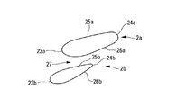
図3および図4に示しているように、主ロッド2aおよび副ロッド2bの長手方向に直角な横断面は、上側25a,25bと下側26a,26bとに加えて、気流の流れる方向における、前縁と呼ばれる前方縁部23a,23bと、前縁23a,23bとは反対側の後縁と呼ばれる後方縁部24a,24bとを備えている。
As shown in FIGS. 3 and 4, the cross section perpendicular to the longitudinal direction of the
なるべくならば、車両上に取り付けられたときの状態において、被払拭表面に略直交する断面の同一の平面に対して相対的に各ロッド2a,2bの下側26a,26bが被払拭表面の方を向くように、主ロッド2aと副ロッド2bとが互いに相対的に配置されているのが好ましい。
If possible, the
更に、前記下側26a,26bの長さは、それぞれ上側25a,25bの長さよりも長くなっている。なるべくならば、下側26a,26bは、それらを上側25a,25bよりも長くすることを可能とするドーム形状を有しているのが好ましい。
Further, the lengths of the
このようにして、主ロッド2aおよび副ロッド2bのプロファイルは、負の揚力の表面を有しており、その表面は特に、前記下側26a,26b付近での減圧区域の創出という結果を生じさせる。
In this way, the profiles of the
上流側端部先端の所で気流は以下の部分へと分割される:
− 前記下側26a,26bのそれぞれに沿って流れ、この気流の部分を長い方の経路に沿って進むように強制するそれら下側のドーム形状のために、気付けば加速させられた状態にある部分(この流れの部分におけるこの加速が、下側26a,26bのそれぞれの付近で少なくとも1つの減圧区域を発生させることを可能とする);
− 前記上側25a,25bのそれぞれに沿って流れ、下側26a,26bを越えるよりも進むべき距離が短いために、気付けば減速させられた状態にある部分(この流れの部分における減速が、上側25a,25bのそれぞれの付近で少なくとも1つの昇圧の区域を発生させることを可能とする)。
At the upstream end tip, the airflow is divided into the following parts:
-Accelerated if noticed, due to their lower dome shape that flows along each of the
-A portion that has flowed along each of the
かくして、下側26a,26bのそれぞれと、上側25a,25bのそれぞれとの間に生み出される圧力差が、結果として得られる被払拭表面の方を向いた力、即ち負の揚力を作り出す。その負の揚力は有利なことに、この被払拭表面に対する前記アーム1のしっかりした押付けを最も効果的なものとする。
Thus, the pressure difference created between each of the
本発明の実施形態の代替的な形態によれば、車両上に取り付けられたときの状態において、被払拭表面上を気流が通常流れる方向に対して、副ロッド2bの前縁23bが主ロッド2aの前縁23aの上流側に位置するようなやり方で、被払拭表面に略直交する断面の全く同一の平面に対して主ロッド2aと副ロッド2bとが互いに対して水平方向へずらされるように、それらの主ロッド2aと副ロッド2bとが互いに相対的に配置されている。かくして、副ロッド2bの前縁23bは概して、被清掃表面を備えた車両が進むときにその被清掃表面上やその付近を流れる空気と接触すべき最初の縁部ということになる。
According to an alternative form of the embodiment of the present invention, the
このようにして、被清掃表面を備えた車両が進むときにその被清掃表面上やその付近を流れる空気は、まず初めに副ロッド2bの前縁23bに、次に主ロード2aの前縁23aにぶつかる。この結果として、副ロッド2bの前縁23b付近に作り出される昇圧区域が、主ロッド2aの前縁23a付近に作り出される減圧区域と干渉することがない。
In this way, the air flowing on or near the surface to be cleaned as the vehicle having the surface to be cleaned travels first to the
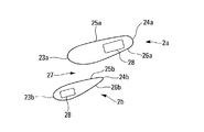
本発明の実施形態の代替的な形態では、車両上に取り付けられたときの状態において、ヴェンチェリ効果によって減圧部が内部に生み出される流路27を主ロッド2aと副ロッド2bとの間に作り出すよう、被払拭表面に略直交する断面の全く同一の平面に対して主ロッド2aと副ロッド2bとが互いに相対的に垂直方向へずらされるように、それらの主ロッド2aと副ロッド2bとが互いに相対的に配置されている。気流は流路27に沿って通過する際に加速される。
In an alternative form of the embodiment of the present invention, when installed on the vehicle, a
有利なことに、ロッド2a,2b同士の間の前記水平方向のずれによって、主ロッド2aの上流側に位置した副ロッド2bのその部分が、流路27に沿って気流が通過する際に発生する効果を蒙らないようにすることが可能となる。またヴェンチェリ効果は、下側26a付近を流れる気流を加速させ、かくして主ロッド2aの負の揚力を増大させる。更に、このロッド2a,2b同士の間の水平方向のずれのために、流れの加速は上側25bの後部上では何ら効果を有さず、ロッド2b上に揚力を生じさせるのを回避することが可能となる。最後に、アーム1の2本のロッド2a,2b同士は、アーム1の移動中、略平行なままであり、ヴェンチェリ効果を一定に保っている。
Advantageously, the horizontal displacement between the
各ロッド2a,2bのプロファイルは、中実であっても中空であってもよく、例えばプラスチック(これは複合型のものであってもよい)や、マグネシウム系合金や、アルミニウムで造り出されていてもよい。各ロッド2a,2bの中空のプロファイルは、(これに限定されるものではないが)特に、ハイドロフォーミング法を用いて、金属シートをプレスして、または真っ直ぐな中空管を変形させることによって造り出されてよい。
The profile of each
なるべくならば、各ロッド2a,2bは、従来のやり方で支持スティック28を備えているのが好ましい。その支持スティック28は、例えば射出成型を用いて当該スティック28の周囲に形成される、上述したタイプの中実型プロファイルによって取り囲まれていてもよい。前記ロッド2a,2bのプロファイルはまた、支持スティック28の周囲にオーバーモールド成型によって形成されていてもよい。
If possible, each
支持スティック28は、略矩形の断面を有しているのが好ましい。但し、支持スティック28の断面の形状は、特にオーバーモールド成型の特性に関連付けられ、或いはロッド2a,2b上を特定のプロファイルで取り囲むための条件に関連付けられる制約によって変化し得る。
The
本発明の実施形態における別の代替的な形態によれば、各ロッド2a,2bの特定のプロファイルは、それぞれ、当該ロッド2a,2bのスティック28に対して例えばクリップ固締によって取り付けることのできる、1つないし複数の独立した構成要素からなっていてもよい。
According to another alternative form of embodiment of the present invention, the specific profile of each
なるべくならば、ロッド2a,2bは次のように構成されているのが好ましい。即ち、洗浄液および/若しくは除氷(防氷)液の流れを案内するパイプのようなパイプ類、並びに/または、ワイパーを加熱式ワイパーとすることのできるように企図された電線などのワイヤ類を通すために長手方向へ延びる少なくとも1つのハウジング(図示せず)を、各ロッド2a,2bが有するようにである。
If possible, the
Claims (9)
前記主ロッド(2a)および副ロッド(2b)のそれぞれが負の揚力の表面プロファイルを備えており、その表面プロファイルの断面が、上側(25a,25b)と、下側(26a,26b)と、気流の方向における、前縁と呼ばれる前方縁部(23a,23b)と、この前縁(23a,23b)とは反対側の後縁と呼ばれる後方縁部(24a,24b)とによって境界を定められていること、並びに、
当該アーム(1)が車両の被払拭表面に対してよりしっかり押し付けられるよう、前記車両上に取り付けられたときの状態において、当該アーム(1)が前記被払拭表面に対して、前記ロッド(2a,2b)の断面における前記下側(26a,26b)が前記被払拭表面の方を向くように配置されていること、を特徴とするワイパーアーム(1)。 In a wiper arm (1) with a pantograph type dynamic action, comprising a main rod (2a) and a secondary rod (2b),
Each of the main rod (2a) and the secondary rod (2b) has a negative lift surface profile, and the cross-sections of the surface profiles are an upper side (25a, 25b), a lower side (26a, 26b), In the direction of the air flow, the front edge (23a, 23b) called the front edge and the rear edge (24a, 24b) called the rear edge opposite to the front edge (23a, 23b) are delimited. As well as
When the arm (1) is mounted on the vehicle so that the arm (1) is pressed more firmly against the surface to be wiped, the rod (2a) , 2b), the wiper arm (1), characterized in that the lower side (26a, 26b) in the cross section of the wiper arm is arranged to face the surface to be wiped.
Applications Claiming Priority (2)
| Application Number | Priority Date | Filing Date | Title |
|---|---|---|---|
| FR1262182A FR2999503B1 (en) | 2012-12-17 | 2012-12-17 | ARM BROOM HOLDER WITH CINEMATIC PANTOGRAPH |
| FR1262182 | 2012-12-17 |
Publications (2)
| Publication Number | Publication Date |
|---|---|
| JP2014139072A true JP2014139072A (en) | 2014-07-31 |
| JP6388473B2 JP6388473B2 (en) | 2018-09-12 |
Family
ID=47902153
Family Applications (1)
| Application Number | Title | Priority Date | Filing Date |
|---|---|---|---|
| JP2013260028A Expired - Fee Related JP6388473B2 (en) | 2012-12-17 | 2013-12-17 | Wiper arm with pantograph-type dynamic action |
Country Status (6)
| Country | Link |
|---|---|
| US (1) | US9789854B2 (en) |
| EP (1) | EP2743147B1 (en) |
| JP (1) | JP6388473B2 (en) |
| CN (1) | CN103863255A (en) |
| FR (1) | FR2999503B1 (en) |
| PL (1) | PL2743147T3 (en) |
Families Citing this family (1)
| Publication number | Priority date | Publication date | Assignee | Title |
|---|---|---|---|---|
| CN109823310A (en) * | 2019-02-13 | 2019-05-31 | 黄洪廉 | Wiper arm is adjusted in lightweight |
Citations (8)
| Publication number | Priority date | Publication date | Assignee | Title |
|---|---|---|---|---|
| JPS56168449U (en) * | 1980-05-17 | 1981-12-12 | ||
| JPS60157946A (en) * | 1983-12-22 | 1985-08-19 | エスベ−エフ・アウト−エレクトリツク・ゲ−エムベ−ハ− | Wiper arm |
| JPS6370463U (en) * | 1986-10-28 | 1988-05-11 | ||
| JPH0872675A (en) * | 1994-09-06 | 1996-03-19 | Mitsuba Electric Mfg Co Ltd | Wind receiving body fitting structure in wiper device |
| JPH10264774A (en) * | 1997-03-25 | 1998-10-06 | Asmo Co Ltd | Pantograph type wiper device |
| JPH11115691A (en) * | 1997-10-16 | 1999-04-27 | Asmo Co Ltd | Wiper blade |
| WO2001040033A1 (en) * | 1999-12-01 | 2001-06-07 | Robert Bosch Gmbh | Wiper device for motor vehicle windscreens |
| JP2006519126A (en) * | 2003-02-28 | 2006-08-24 | ローベルト ボツシユ ゲゼルシヤフト ミツト ベシユレンクテル ハフツング | Wiper device |
Family Cites Families (12)
| Publication number | Priority date | Publication date | Assignee | Title |
|---|---|---|---|---|
| US3404423A (en) * | 1965-06-24 | 1968-10-08 | Trico Products Corp | Windshield cleaning apparatus |
| US3418678A (en) * | 1966-06-10 | 1968-12-31 | Trico Products Corp | Windshield wiper arm and blade assembly |
| DE2250509C3 (en) * | 1972-10-14 | 1979-08-09 | Robert Bosch Gmbh, 7000 Stuttgart | Wiper system for motor vehicle windows |
| GB2140287B (en) * | 1983-05-24 | 1986-04-16 | Trico Folberth Ltd | Anti-windlift wiper arm and blade assemblies |
| DE3525739A1 (en) * | 1985-07-19 | 1987-01-29 | Swf Auto Electric Gmbh | WIPER ARM, ESPECIALLY FOR WIPING SYSTEMS ON MOTOR VEHICLES AND METHOD FOR THE PRODUCTION THEREOF |
| FR2761322B1 (en) * | 1997-03-25 | 1999-05-14 | Valeo Systemes Dessuyage | WINDSCREEN WIPER WITH IMPROVED AESTHETIC PANTOGRAPH, ESPECIALLY FOR MOTOR VEHICLE |
| DE19747857A1 (en) * | 1997-10-30 | 1999-05-06 | Bosch Gmbh Robert | Wiper arm for a wiper |
| FR2785248B1 (en) * | 1998-10-28 | 2000-12-01 | Valeo Systemes Dessuyage | WINDSCREEN WIPER ARM CONFORMING TO AERODYNAMIC DEFLECTOR |
| KR100317799B1 (en) * | 2000-06-01 | 2002-01-09 | 최동섭 | wind shield wiper arm |
| DE10341280A1 (en) * | 2003-09-08 | 2005-03-31 | Robert Bosch Gmbh | wiper device |
| FR2919248B1 (en) * | 2007-07-26 | 2010-01-15 | Valeo Systemes Dessuyage | AERODYNAMIC WIPING DEVICE FOR A GLASS OF A MOTOR VEHICLE. |
| EP2300282A1 (en) * | 2008-07-22 | 2011-03-30 | NV Bekaert SA | Composite wiper arm |
-
2012
- 2012-12-17 FR FR1262182A patent/FR2999503B1/en active Active
-
2013
- 2013-12-17 US US14/108,867 patent/US9789854B2/en not_active Expired - Fee Related
- 2013-12-17 EP EP13197883.5A patent/EP2743147B1/en active Active
- 2013-12-17 JP JP2013260028A patent/JP6388473B2/en not_active Expired - Fee Related
- 2013-12-17 PL PL13197883T patent/PL2743147T3/en unknown
- 2013-12-17 CN CN201310693801.6A patent/CN103863255A/en active Pending
Patent Citations (9)
| Publication number | Priority date | Publication date | Assignee | Title |
|---|---|---|---|---|
| JPS56168449U (en) * | 1980-05-17 | 1981-12-12 | ||
| JPS60157946A (en) * | 1983-12-22 | 1985-08-19 | エスベ−エフ・アウト−エレクトリツク・ゲ−エムベ−ハ− | Wiper arm |
| JPS6370463U (en) * | 1986-10-28 | 1988-05-11 | ||
| JPH0872675A (en) * | 1994-09-06 | 1996-03-19 | Mitsuba Electric Mfg Co Ltd | Wind receiving body fitting structure in wiper device |
| JPH10264774A (en) * | 1997-03-25 | 1998-10-06 | Asmo Co Ltd | Pantograph type wiper device |
| JPH11115691A (en) * | 1997-10-16 | 1999-04-27 | Asmo Co Ltd | Wiper blade |
| WO2001040033A1 (en) * | 1999-12-01 | 2001-06-07 | Robert Bosch Gmbh | Wiper device for motor vehicle windscreens |
| JP2003515495A (en) * | 1999-12-01 | 2003-05-07 | ローベルト ボツシユ ゲゼルシヤフト ミツト ベシユレンクテル ハフツング | Wiper device for automotive window glass |
| JP2006519126A (en) * | 2003-02-28 | 2006-08-24 | ローベルト ボツシユ ゲゼルシヤフト ミツト ベシユレンクテル ハフツング | Wiper device |
Also Published As
| Publication number | Publication date |
|---|---|
| US9789854B2 (en) | 2017-10-17 |
| FR2999503A1 (en) | 2014-06-20 |
| EP2743147B1 (en) | 2016-09-07 |
| FR2999503B1 (en) | 2017-09-15 |
| US20140165319A1 (en) | 2014-06-19 |
| CN103863255A (en) | 2014-06-18 |
| JP6388473B2 (en) | 2018-09-12 |
| PL2743147T3 (en) | 2017-06-30 |
| EP2743147A1 (en) | 2014-06-18 |
Similar Documents
| Publication | Publication Date | Title |
|---|---|---|
| US3037233A (en) | Windscreen wipers | |
| JP4191492B2 (en) | Windshield wiper device | |
| CN105270341B (en) | Connecting device between a wiper arm and a wiper blade | |
| CN103260990B (en) | Vehicle component with air overflow groove and its vehicle | |
| JP2011516324A (en) | A windscreen wiper device comprising an elongated wiper blade made of a flexible material that is stretchable and is installed in contact with an elongated carrier element and a windshield to be wiped | |
| JP6388473B2 (en) | Wiper arm with pantograph-type dynamic action | |
| US20160167623A1 (en) | Semi-rigid windshield wiper blade having an offset spoiler | |
| JP2018172063A (en) | Vehicle body structure | |
| JP3612542B2 (en) | Wiper blade structure for automobile | |
| US10807656B2 (en) | Air directing apparatus for a motor vehicle | |
| JP5445586B2 (en) | Wing structure and rectifier | |
| CN101918252B (en) | Windscreen wiper device | |
| CN205632413U (en) | Aircraft windscreen wiper brush arm | |
| JP7567690B2 (en) | Wiper blades | |
| CN204340604U (en) | A kind of air baffle for vehicle dormer window | |
| JP7387356B2 (en) | Windshield wiper system blade assembly and its assembly method | |
| JP2010058701A (en) | Wiper device for vehicle | |
| JP2009220709A (en) | Wiper blade | |
| MY192283A (en) | Vehicle structure | |
| JP5996477B2 (en) | Vehicle cleaning device | |
| EP3750761A1 (en) | Terminal part for a wiper arm | |
| KR101158671B1 (en) | Wiper blade having reattachable spoiler | |
| JP2012091670A (en) | Vehicle wiper | |
| JP2003231456A (en) | Vehicle wiper blade | |
| JP2019051854A (en) | Wiper device |
Legal Events
| Date | Code | Title | Description |
|---|---|---|---|
| RD03 | Notification of appointment of power of attorney |
Free format text: JAPANESE INTERMEDIATE CODE: A7423 Effective date: 20161117 |
|
| A621 | Written request for application examination |
Free format text: JAPANESE INTERMEDIATE CODE: A621 Effective date: 20161205 |
|
| A977 | Report on retrieval |
Free format text: JAPANESE INTERMEDIATE CODE: A971007 Effective date: 20171025 |
|
| A131 | Notification of reasons for refusal |
Free format text: JAPANESE INTERMEDIATE CODE: A131 Effective date: 20171107 |
|
| A521 | Request for written amendment filed |
Free format text: JAPANESE INTERMEDIATE CODE: A523 Effective date: 20180207 |
|
| TRDD | Decision of grant or rejection written | ||
| A01 | Written decision to grant a patent or to grant a registration (utility model) |
Free format text: JAPANESE INTERMEDIATE CODE: A01 Effective date: 20180717 |
|
| A61 | First payment of annual fees (during grant procedure) |
Free format text: JAPANESE INTERMEDIATE CODE: A61 Effective date: 20180814 |
|
| R150 | Certificate of patent or registration of utility model |
Ref document number: 6388473 Country of ref document: JP Free format text: JAPANESE INTERMEDIATE CODE: R150 |
|
| LAPS | Cancellation because of no payment of annual fees |