JP2014137125A - Motion guide device - Google Patents
Motion guide device Download PDFInfo
- Publication number
- JP2014137125A JP2014137125A JP2013007113A JP2013007113A JP2014137125A JP 2014137125 A JP2014137125 A JP 2014137125A JP 2013007113 A JP2013007113 A JP 2013007113A JP 2013007113 A JP2013007113 A JP 2013007113A JP 2014137125 A JP2014137125 A JP 2014137125A
- Authority
- JP
- Japan
- Prior art keywords
- rolling element
- path
- guide surface
- groove
- peripheral side
- Prior art date
- Legal status (The legal status is an assumption and is not a legal conclusion. Google has not performed a legal analysis and makes no representation as to the accuracy of the status listed.)
- Granted
Links
Images


Classifications
-
- F—MECHANICAL ENGINEERING; LIGHTING; HEATING; WEAPONS; BLASTING
- F16—ENGINEERING ELEMENTS AND UNITS; GENERAL MEASURES FOR PRODUCING AND MAINTAINING EFFECTIVE FUNCTIONING OF MACHINES OR INSTALLATIONS; THERMAL INSULATION IN GENERAL
- F16C—SHAFTS; FLEXIBLE SHAFTS; ELEMENTS OR CRANKSHAFT MECHANISMS; ROTARY BODIES OTHER THAN GEARING ELEMENTS; BEARINGS
- F16C29/00—Bearings for parts moving only linearly
- F16C29/04—Ball or roller bearings
- F16C29/06—Ball or roller bearings in which the rolling bodies circulate partly without carrying load
- F16C29/0633—Ball or roller bearings in which the rolling bodies circulate partly without carrying load with a bearing body defining a U-shaped carriage, i.e. surrounding a guide rail or track on three sides
- F16C29/0669—Ball or roller bearings in which the rolling bodies circulate partly without carrying load with a bearing body defining a U-shaped carriage, i.e. surrounding a guide rail or track on three sides whereby the main body of the U-shaped carriage is an assembly of at least three major parts, e.g. an assembly of a top plate with two separate legs attached thereto in the form of bearing shoes
- F16C29/0671—Ball or roller bearings in which the rolling bodies circulate partly without carrying load with a bearing body defining a U-shaped carriage, i.e. surrounding a guide rail or track on three sides whereby the main body of the U-shaped carriage is an assembly of at least three major parts, e.g. an assembly of a top plate with two separate legs attached thereto in the form of bearing shoes with balls
-
- F—MECHANICAL ENGINEERING; LIGHTING; HEATING; WEAPONS; BLASTING
- F16—ENGINEERING ELEMENTS AND UNITS; GENERAL MEASURES FOR PRODUCING AND MAINTAINING EFFECTIVE FUNCTIONING OF MACHINES OR INSTALLATIONS; THERMAL INSULATION IN GENERAL
- F16C—SHAFTS; FLEXIBLE SHAFTS; ELEMENTS OR CRANKSHAFT MECHANISMS; ROTARY BODIES OTHER THAN GEARING ELEMENTS; BEARINGS
- F16C29/00—Bearings for parts moving only linearly
- F16C29/04—Ball or roller bearings
- F16C29/06—Ball or roller bearings in which the rolling bodies circulate partly without carrying load
- F16C29/0602—Details of the bearing body or carriage or parts thereof, e.g. methods for manufacturing or assembly
- F16C29/0609—Details of the bearing body or carriage or parts thereof, e.g. methods for manufacturing or assembly of the ends of the bearing body or carriage where the rolling elements change direction, e.g. end caps
-
- F—MECHANICAL ENGINEERING; LIGHTING; HEATING; WEAPONS; BLASTING
- F16—ENGINEERING ELEMENTS AND UNITS; GENERAL MEASURES FOR PRODUCING AND MAINTAINING EFFECTIVE FUNCTIONING OF MACHINES OR INSTALLATIONS; THERMAL INSULATION IN GENERAL
- F16C—SHAFTS; FLEXIBLE SHAFTS; ELEMENTS OR CRANKSHAFT MECHANISMS; ROTARY BODIES OTHER THAN GEARING ELEMENTS; BEARINGS
- F16C29/00—Bearings for parts moving only linearly
- F16C29/04—Ball or roller bearings
- F16C29/06—Ball or roller bearings in which the rolling bodies circulate partly without carrying load
- F16C29/0633—Ball or roller bearings in which the rolling bodies circulate partly without carrying load with a bearing body defining a U-shaped carriage, i.e. surrounding a guide rail or track on three sides
- F16C29/0635—Ball or roller bearings in which the rolling bodies circulate partly without carrying load with a bearing body defining a U-shaped carriage, i.e. surrounding a guide rail or track on three sides whereby the return paths are provided as bores in a main body of the U-shaped carriage, e.g. the main body of the U-shaped carriage is a single part with end caps provided at each end
- F16C29/0638—Ball or roller bearings in which the rolling bodies circulate partly without carrying load with a bearing body defining a U-shaped carriage, i.e. surrounding a guide rail or track on three sides whereby the return paths are provided as bores in a main body of the U-shaped carriage, e.g. the main body of the U-shaped carriage is a single part with end caps provided at each end with balls
- F16C29/0642—Ball or roller bearings in which the rolling bodies circulate partly without carrying load with a bearing body defining a U-shaped carriage, i.e. surrounding a guide rail or track on three sides whereby the return paths are provided as bores in a main body of the U-shaped carriage, e.g. the main body of the U-shaped carriage is a single part with end caps provided at each end with balls with four rows of balls
- F16C29/0647—Ball or roller bearings in which the rolling bodies circulate partly without carrying load with a bearing body defining a U-shaped carriage, i.e. surrounding a guide rail or track on three sides whereby the return paths are provided as bores in a main body of the U-shaped carriage, e.g. the main body of the U-shaped carriage is a single part with end caps provided at each end with balls with four rows of balls with load directions in X-arrangement
-
- F—MECHANICAL ENGINEERING; LIGHTING; HEATING; WEAPONS; BLASTING
- F16—ENGINEERING ELEMENTS AND UNITS; GENERAL MEASURES FOR PRODUCING AND MAINTAINING EFFECTIVE FUNCTIONING OF MACHINES OR INSTALLATIONS; THERMAL INSULATION IN GENERAL
- F16C—SHAFTS; FLEXIBLE SHAFTS; ELEMENTS OR CRANKSHAFT MECHANISMS; ROTARY BODIES OTHER THAN GEARING ELEMENTS; BEARINGS
- F16C33/00—Parts of bearings; Special methods for making bearings or parts thereof
- F16C33/30—Parts of ball or roller bearings
- F16C33/38—Ball cages
- F16C33/3825—Ball cages formed as a flexible belt, e.g. spacers connected by a thin film
Landscapes
- Engineering & Computer Science (AREA)
- General Engineering & Computer Science (AREA)
- Mechanical Engineering (AREA)
- Bearings For Parts Moving Linearly (AREA)
Abstract
【課題】案内溝に対するベルト部材の干渉を防いで、無限循環路内での転動体の円滑な循環を可能とする運動案内装置を提供する。
【解決手段】転動体5と、この転動体が転走する軌道レールと、転動体の無限循環路を備える移動ブロックと、前記無限循環路内に収容される連結体を備え、前記無限循環路は負荷転動体通路31、転動体戻し通路32及び方向転換路45を有し、この無限循環路内には前記連結体を案内する案内溝91が形成され、前記方向転換路に形成された案内溝91は外周側案内面とこれに対向する内周側案内面を有すると共にこれら外周側案内面44及び内周側案内面87は夫々が滑らか連続し、その溝幅は前記負荷転動体通路又は転動体戻し通路との連結端から方向転換路の中央部に至るまでの経路途上で最大となり、且つ、前記連結端の溝幅及び前記中央部の溝幅は前記経路途上における溝幅の最大値よりも小さく設定される。
【選択図】図11A motion guide device is provided that prevents a belt member from interfering with a guide groove and enables smooth circulation of rolling elements in an infinite circulation path.
The rolling element includes a rolling element, a track rail on which the rolling element rolls, a moving block including an infinite circulation path of the rolling element, and a connecting body accommodated in the infinite circulation path, and the infinite circulation path. Has a load rolling element passage 31, a rolling element return passage 32, and a direction changing path 45. A guide groove 91 for guiding the connecting body is formed in the infinite circulation path, and the guide formed in the direction changing path is formed. The groove 91 has an outer peripheral side guide surface and an inner peripheral side guide surface opposite to the outer peripheral side guide surface, and the outer peripheral side guide surface 44 and the inner peripheral side guide surface 87 are each smoothly continuous, and the groove width thereof is the load rolling element passage It becomes the maximum on the way from the connecting end to the rolling element return passage to the center part of the direction change path, and the groove width of the connecting end and the groove width of the central part are the maximum values of the groove width on the way Is set smaller.
[Selection] Figure 11
Description
本発明は、転動体の無限循環路内に多数の転動体を等間隔で整列させるための連結体を組み込んだ運動案内装置に関する。 The present invention relates to a motion guide device incorporating a connecting body for aligning a large number of rolling elements at equal intervals in an infinite circulation path of the rolling elements.
この種の運動案内装置は、長手方向に沿って転動体の転走面が形成された軌道レールと、多数の転動体を介して軌道レールに組み付けられると共にこれら転動体の無限循環路を有する移動ブロックと、前記無限循環路内に配列された多数の転動体と、これら転動体と共に前記無限循環路内に組み込まれて当該転動体を等間隔で一列に整列させるベルト状の連結体とを備えている。また、前記連結体は、隣接する転動体間に配置される複数のスペーサと、これらスペーサを等間隔で一列に連結するベルト部材とから構成されている。そして、移動ブロックが軌道レールに対して相対的に往復運動を行なうと、前記転動体が前記無限循環路内を循環し、併せて前記連結体が転動体と共に前記無限循環路内を循環するように構成されている。 This type of motion guide device is a track rail in which the rolling surfaces of the rolling elements are formed along the longitudinal direction, and a movement that is assembled to the track rail via a large number of rolling elements and has an infinite circulation path for these rolling elements. A block, a large number of rolling elements arranged in the endless circulation path, and a belt-like coupling body that is incorporated in the endless circulation path together with the rolling elements and aligns the rolling elements in a row at equal intervals. ing. Moreover, the said connection body is comprised from the several spacer arrange | positioned between adjacent rolling elements, and the belt member which connects these spacers in a line at equal intervals. When the moving block reciprocates relative to the track rail, the rolling element circulates in the infinite circuit, and the connecting body circulates in the infinite circuit with the rolling element. It is configured.
前記無限循環路は、転動体が軌道レールと移動ブロックとの間で荷重を受けながら転動する負荷転動体通路と、この負荷転動体通路と平行に設けられた転動体戻し通路と、前記負荷転動体通路と転動体戻し通路とを接続する一対の方向転換路とから構成され、各方向転換路は転動体及び連結体の進行方向を反転させるべく、一定の曲率半径で円弧状に形成されている。また、前記負荷転動体通路、転動体戻し通路及び方向転換路の内壁には前記転動体の循環方向に沿って前記連結体のベルト部に対応した案内溝が形成されており、前記連結体はそのベルト部が前記案内溝に挿入された状態で前記無限循環路内を循環するようになっている。前記方向転換路における案内溝はその曲率中心が当該方向転換路の曲率中心と合致しており、当該方向転換路と同様に一定の曲率半径で円弧状に形成されている。 The infinite circulation path includes a load rolling element passage where the rolling element rolls while receiving a load between the track rail and the moving block, a rolling element return passage provided in parallel with the load rolling element passage, and the load It is composed of a pair of direction changing paths connecting the rolling element passage and the rolling element return passage, and each direction changing path is formed in an arc shape with a constant radius of curvature so as to reverse the traveling direction of the rolling elements and the coupling body. ing. In addition, a guide groove corresponding to a belt portion of the connecting body is formed along an inner wall of the load rolling element passage, the rolling element return path, and the direction changing path along the circulation direction of the rolling element. The belt portion circulates in the endless circuit with the belt inserted in the guide groove. The center of curvature of the guide groove in the direction change path coincides with the center of curvature of the direction change path, and is formed in an arc shape with a constant radius of curvature as in the direction change path.
前記連結体が前記方向転換路内を移動する際、前記ベルト部材は前記案内溝に合致した円弧状に湾曲するのではなく、互いに隣接するスペーサの間で局所的に屈曲しながら前記案内溝の円弧に近似した形状に湾曲する。このため、前記連結体が方向転換路内を移動する際には、前記ベルト部材が前記案内溝の外周面に干渉し易く、それに伴って方向転換路内における連結体に余分な摺動抵抗が作用する懸念があった。このようなベルト部材と案内溝との干渉を考慮したものとして特許文献1記載の発明がある。この発明では、前記案内溝の外周面の曲率中心を前記方向転換路の曲率中心よりも当該方向転換路の外周面側に配置しており、それによって前記案内溝の幅は方向転換路の両端部から中央部にかけて徐々に拡がり、中央部で最大の溝幅となっていた。 When the connecting body moves in the direction change path, the belt member is not curved in an arc shape matching the guide groove, but is bent locally between the spacers adjacent to each other. Curves to a shape that approximates an arc. For this reason, when the connection body moves in the direction change path, the belt member easily interferes with the outer peripheral surface of the guide groove, and accordingly, the connection body in the direction change path has an excessive sliding resistance. There was concern to work. There is an invention described in Patent Document 1 in consideration of such interference between the belt member and the guide groove. In this invention, the center of curvature of the outer peripheral surface of the guide groove is arranged on the outer peripheral surface side of the direction change path with respect to the center of curvature of the direction change path, whereby the width of the guide groove is equal to both ends of the direction change path. It gradually expanded from the center to the center, and was the maximum groove width in the center.
本発明が目的とするところは、前記案内溝に対する連結体のベルト部材の干渉を防いで前記方向転換路内におけるベルト部材の循環を円滑にすることができ、もって無限循環路内での転動体の円滑な循環を可能とする運動案内装置を提供することにある。 An object of the present invention is to prevent the belt member of the coupling body from interfering with the guide groove, and to smoothly circulate the belt member in the direction change path, so that the rolling element in the infinite circulation path can be achieved. An object of the present invention is to provide a motion guide device that can smoothly circulate.
このような目的を達成する本発明の運動案内装置は、長手方向に沿って転動体が転走する軌道レールと、多数の転動体を介して前記軌道レールに組み付けられると共に当該転動体の無限循環路を有し、当該軌道レールに沿って移動自在な移動ブロックとを備え、前記無限循環路は、前記転動体が軌道レールとの間で荷重を負荷しながら転走する負荷転動体通路と、この負荷転動体通路と平行な転動体戻し通路と、前記負荷転動体通路と転動体戻し通路とを繋ぐ方向転換路とを備える。また、前記無限循環路内に配列された複数の転動体は、互いに隣接する転動体の間に配置されるスペーサ及び各スペーサを連結するベルト部材を備えた連結体によって保持されている。 The motion guide device of the present invention that achieves such an object includes a track rail on which rolling elements roll along the longitudinal direction, and an infinite circulation of the rolling elements that are assembled to the track rail via a number of rolling elements. And a moving block that is movable along the track rail, and the infinite circulation path is a load rolling element passage that rolls while the rolling element loads a load with the track rail, A rolling element return path parallel to the load rolling element path and a direction changing path connecting the load rolling element path and the rolling element return path are provided. Further, the plurality of rolling elements arranged in the endless circulation path are held by a connecting body including a spacer disposed between the adjacent rolling elements and a belt member that connects the spacers.
そして、前記無限循環路内には前記連結体のベルト部材を転動体の循環方向に沿って案内する案内溝が形成され、前記方向転換路内に形成された案内溝は外周側案内面とこれに対向する内周側案内面を有し、これら外周側案内面及び内周側案内面は夫々が滑らかに連続している。更に、前記方向転換路内に形成された案内溝の溝幅は、前記負荷転動体通路又は転動体戻し通路との連結端から当該方向転換路の中央部に至るまでの経路途上で最大となり、且つ、前記連結端における溝幅及び前記中央部における溝幅は、前記経路途上における溝幅の最大値よりも小さく設定されている。 A guide groove for guiding the belt member of the coupling body along the circulation direction of the rolling element is formed in the endless circulation path, and the guide groove formed in the direction change path is formed on the outer circumferential guide surface and the guide groove. The outer peripheral side guide surface and the inner peripheral side guide surface are smoothly continuous with each other. Furthermore, the groove width of the guide groove formed in the direction change path becomes the maximum on the way from the connecting end with the load rolling element passage or the rolling element return path to the center of the direction change path, And the groove width in the said connection end and the groove width in the said center part are set smaller than the maximum value of the groove width in the said path course.
本発明の運動案内装置によれば、前記方向転換路内にてベルト部材が屈曲したとしても、このベルト部材が前記方向転換路に形成された案内溝に干渉するのを防ぐことが可能となる。その結果、前記無限循環路内での転動体の円滑な循環を達成することができ、ひいては軌道レールに沿った移動ブロックの円滑な移動を達成することが可能となる。 According to the motion guide device of the present invention, even if the belt member is bent in the direction change path, it is possible to prevent the belt member from interfering with the guide groove formed in the direction change path. . As a result, it is possible to achieve smooth circulation of the rolling elements in the endless circulation path, and consequently, it is possible to achieve smooth movement of the moving block along the track rail.
以下、添付図面を用いて本発明を適用した運動案内装置の実施形態を詳細に説明する。 DESCRIPTION OF EMBODIMENTS Hereinafter, embodiments of a motion guide device to which the present invention is applied will be described in detail with reference to the accompanying drawings.
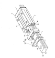
図1は本発明を適用した運動案内装置の実施形態の一例を示すものである。この運動案内装置は、直線状に延びる軌道レール1と、転動体としての多数のボールを介して前記軌道レール1に組付けられると共に当該ボールの無限循環路を有する移動ブロック2とを備え、前記移動ブロック2は軌道レール1に沿って往復運動自在に移動することが可能である。尚、図1は、前記軌道レール1及び移動ブロック2の全体像を理解し易くするため、前記無限循環路内に配列されるボールを省略して描いてある。
FIG. 1 shows an example of an embodiment of a motion guide device to which the present invention is applied. The motion guide device includes a linearly extending track rail 1 and a moving
前記軌道レール1は断面略矩形状に形成されている。この軌道レール1の左右両側面には長手方向に沿って突部10が設けられている。各突部10の上側及び下側にはボール転走溝11が夫々設けられており、前記軌道レール1には計4条のボール転走溝11が形成されている。また、前記軌道レール1には長手方向に沿って所定の間隔で上面から底面に貫通するボルト取付け孔12が形成されている。このボルト取付け孔12は前記軌道レール1を機械装置などに敷設する際に利用される。尚、この軌道レール1に対するボール転走溝11の配置及び条数は、移動ブロック2に必要とされる負荷能力に応じて適宜変更して良い。
The track rail 1 has a substantially rectangular cross section.
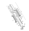
一方、前記移動ブロック2は、前記軌道レール1の一部を収容するブロック組立体3と、このブロック組立体3の往復移動方向の両端に装着される一対のエンドプレート4とを備えている。このエンドプレート4は、エンドプレート本体40と、このエンドプレート本体40に固定されるシール保持プレート41とから構成される。前記シール保持プレート41にはシール部材42が装着されており、かかるシール部材42がエンドプレート4と軌道レール1との隙間を密封し、軌道レール1に付着した塵芥などが移動ブロック2の内部に進入するのを防止している。尚、図1では、一方のエンドプレート4を前記ブロック組立体3から取り外し、更に当該エンドプレート4をエンドプレート本体40とシール保持プレート41とに分解した状態を示している。
On the other hand, the moving
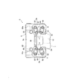
図2は、前記エンドプレート4を取り除いた状態の運動案内装置を示す正面図である。前記ブロック組立体3は、テーブル等の搬送対象物の取付面20が形成された水平部3aと、この水平部3aと直交すると共に前記軌道レール1の両側面に対向する一対の脚部3bとを有しており、前記ブロック組立体3は一対の脚部3bの間に前記軌道レール1の上半分を収容している。また、前記取付面20には搬送対象物をボルトで固定するためのタップ穴20aが設けられている。
FIG. 2 is a front view showing the motion guide device with the
前記軌道レール1に面した各脚部3bの内側には2条の負荷ボール転走溝30が設けられている。これら負荷ボール転走溝30は前記軌道レール1のボール転走溝11に対向し、ボール5が荷重を負荷しながら転走する負荷転動体通路31を構成する。また、各脚部3bには各負荷転動体通路31と略平行に転動体戻し通路32が設けられている。この転動体戻し通路32の内径はボール5の直径よりも僅かに大きく設定されており、ボール5は荷重から開放された状態でこの転動体戻し通路32内を転走する。
Two load
尚、図2において、符号33は前記エンドプレート4の固定に用いるタップ穴、符号34は軌道レール1の側面とブロック組立体3の脚部3bとの間を密封するシール部材、符号35は軌道レール1の上面とブロック組立体3の水平部3aとの間を密封するシール部材である。
In FIG. 2,
また、前記エンドプレート4は前記ブロック組立体3と相まって前記無限循環路の一部をなす方向転換路を形成する。この方向転換路は一定の曲率半径で円弧状に形成されて前記負荷転動体通路31と転動体戻し通路32を連結し、ボール5を負荷転動体通路31と転動体戻し通路32との間で往来させることが可能になっている。すなわち、図1に示したように、前記ブロック組立体3に一対のエンドプレート4を装着することで、前記ボール5の無限循環路が完成する。
Also, the
更に、前記ボール5はベルト状の連結体6に等間隔で一列に配列されており、この連結体と共に前記負荷転動体通路31、転動体戻し通路32及び方向転換路から構成される無限循環路に組み込まれている。但し、図2では方向転換路に配列されたボール5及び連結体6を省略して描いており、前記負荷転動体通路31及び転動体戻し通路32における連結体6の断面が示されている。
Further, the
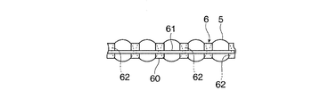
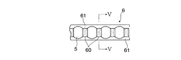
図3乃至図5は前記連結体6を示すものである。この連結体6は、各ボール5間に配置される複数のスペーサ60と、ボール5の配列方向に沿って延びてこれらスペーサ60を連結する一対のベルト部材61とを備えている。各スペーサ60は円盤状に形成されると共に、ボール5と接触する面には球面座62が設けられ、この球面座62はボール5の球面に近似した曲率になっている。また、前記ベルト部材61は可撓性を有して平帯状に形成されている。一対のベルト部材61は前記スペーサ60を挟んで配置されており、当該スペーサ60と結合されている。このため、ベルト部材61はスペーサ60との結合部位では撓みにくく、スペーサ60と結合されていない部位、すなわち互いに隣接するスペーサ60の間において撓み易くなっている。従って、前記方向転換路内で連結体6を強制的に湾曲させた場合、前記連結体6は滑らかな円弧状に湾曲するのではなく、部分的な屈曲を伴って擬似的な円弧状に湾曲することになる。また、図3に示すように、前記ベルト部材61はボール5の中心より僅かに変位した位置で前記スペーサ60と結合されており、この連結体6を移動ブロック2の無限循環路に組み込む際には、前記ベルト部材61がボール5の中心よりも循環経路の内側に存在するように当該連結体6の移動ブロック2に対する組み込み姿勢を決定する。
3 to 5 show the connecting
この連結体6は合成樹脂の射出成形によって前記スペーサ60とベルト部材61とが一体的に製作され、ボール5は当該連結体6の製作後にスペーサ60の間に挿入される。一対のスペーサ60の間に挿入されたボール5はこれらスペーサ60によって抱え込まれ、回転自在な状態で連結体に保持されている。また、各スペーサ60は前記球面座62でボール5に接触することから、前記移動ブロック2の無限循環路内で連結体6が湾曲した状態において、当該スペーサ60は常にその球面座62の中心が互いに隣接するボール5の中心を結ぶ線分上に位置している。
In this
図6は前記無限循環路に組み込まれた連結体6を示す断面図である。この無限循環路は前記負荷転動体通路31と転動体戻し通路32とを一対の方向転換路45で連結して構成されており、円弧状の各方向転換路45においてボール5の進行方向が反転し、負荷転動体通路31から転動体戻し通路32へ、転動体戻し通路32から負荷転動体通路31へボールが送り込まれるようになっている。前記無限循環路内では、前記連結体6の端部6a、6b同士が隙間を介して互いに対向しており、連結体6が僅かに伸長した場合でも端部同士が干渉しないように構成されている。従って、移動ブロック2が軌道レール1に沿って運動すると、負荷転動体通路31に存在するボール5が転動し、これに伴って無限循環路内に存在する総てのボール5が連結体6と共に当該無限循環路内を循環することになる。
FIG. 6 is a cross-sectional view showing the connecting
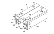
次に、前記ブロック組立体3及びエンドプレート4の構成を詳細に説明する。図7は前記ブロック組立体3の斜視図、図8はブロック組立体3の分解図である。このブロック組立体3は、前記負荷ボール転走溝30が形成された金属製のブロック本体7と、このブロック本体7に対して装着される合成樹脂製の一対の循環部材8と、前記ブロック本体7に装着されて前記転動体戻し通路32となる4本のパイプ部材9とから構成される。
Next, the configuration of the
前記ブロック本体7には移動ブロック2の移動方向に沿った取付け孔70が貫通形成されている。前記パイプ部材9は断面略半円状に形成された一対のパイプ半体9a,9bからなり、このパイプ部材9が取付け孔70に挿入されることで前記転動体戻し通路32が形成される。また、図7及び図8には示されていないが、前記パイプ部材9の内壁には前記連結体6のベルト部材61が収容される案内溝が形成されている。
A mounting
また、前記循環部材8は前記ブロック組立体3の各脚部3bに対応して設けられており、前記ブロック本体7の両端面に接する一対のインナプレート80と、これらインナプレート80を互いに連結する三本の保持枠81,82,83と、から構成される。各インナプレート80はブロック本体7の端面の一部を覆う平板状に形成されると共に、前記パイプ部材9が挿入されるパイプ保持孔84が設けられ、このパイプ保持孔84が前記転動体戻し通路32の入口又は出口となる。また、各インナプレート80には前記パイプ保持孔84に隣接して二つの案内突起85が形成されており、各案内突起85は前記インナプレート80の表面から半円形状に突出すると共に、当該インナプレート80と一体に成形されている。更に、各案内突起85にはその周面に沿って一定の曲率半径で内周曲面86が形成されており、この内周曲面86の一端は前記負荷ボール転走溝30に、他端は転動体戻し通路32に連続している。また、この内周曲面86の両側には前記連結体6のベルト部材61が摺接する一対の内周側案内面87が形成されており、これら内周側案内面87は前記案内突起85の外周縁をなしている。
The circulation member 8 is provided corresponding to each
一方、第一の保持枠81は前記脚部3bに形成された2条の負荷ボール転走溝30のうち、上側の負荷ボール転走溝30の上端縁に沿って設けられる一方、第二の保持枠82は2条の負荷ボール転走溝30の中間に位置するように設けられている。また、第三の保持枠83は脚部3bの下端に位置して下側の負荷ボール転走溝30の下端に沿って設けられている。更に、これらの保持枠81,82,83の負荷ボール転走溝30に面した部位には、前記連結体6のベルト部材61を収容する案内溝が設けられており、各案内溝が前記負荷ボール転走溝の30の両側に位置して、連結体6のベルト部材61の通路を構成する。
On the other hand, the
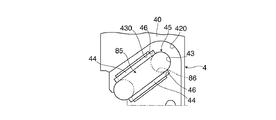
一方、図9は前記エンドプレート4のブロック組立体3との接合面を示す詳細図である。エンドプレート4を構成するエンドプレート本体40のブロック組立体3との接合面には、前記循環部材8のインナプレート80と同一形状のプレート固定溝420が形成されており、エンドプレート本体40をブロック組立体3に固定すると、前記インナプレート80がプレート固定溝420に嵌合して位置決めされると共に、エンドプレート本体40とブロック本体7との間に挟み込まれて固定されるようになっている。また、前記プレート固定溝420の内部にはインナプレート80の案内突起85が嵌合する突起収容溝430が形成されている。この突起収容溝430は案内突起85の内周曲面86と対向する外周曲面43を具備しており、エンドプレート4をブロック組立体3に装着すると、前記案内突起85の内周曲面86と突起収容溝430の外周曲面43とが組み合わさって、両者の間にボール5の直径よりも僅かに大きな内径の方向転換路45が構成される。更に、前記突起収容溝430と案内突起85とが組み合わさることにより、前記連結体6のベルト部材61を収容する案内溝46が方向転換路45に具備されるようになっている。この案内溝46は前記案内突起85の内周曲面86の両側に設けられた内周側案内面87対向する外周側案内面44を有している。尚、図9中においては方向転換路45の存在を明確にするため、ブロック組立体3側の案内突起85を二点鎖線で示してある。
On the other hand, FIG. 9 is a detailed view showing a joint surface of the
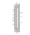
図10は前記ブロック組立体3に対してエンドプレート4を装着し、前記方向転換路45を完成させた状態を示す断面図である。前記エンドプレート4に設けられた前記外周曲面43は前記転動体戻し通路32から連続する半円状に形成されており、この外周曲面43は前記内周曲面86と同一の曲率中心で、且つ内周曲面86の曲率半径よりもボール直径分より僅かに大きな曲率半径で円弧状に形成されている。前記ブロック組立体3に対してエンドプレート4を装着すると、前記案内突起85の内周曲面86と前記外周曲面43とが対向し、両者の間に前記負荷転動体通路31と転動体戻し通路32とを繋ぐ半円状の方向転換路45が完成する。また、前記方向転換路45内には、前記外周側案内面44と前記内周側案内面87が対向することにより、前記連結体6のベルト部材61を収容する案内溝46が具備される。
FIG. 10 is a sectional view showing a state in which the
更に、前記ブロック本体7の取付け孔70に挿入されたパイプ部材9の一部は当該取付け孔70から突出し、前記循環部材8のインナプレート80に形成されたパイプ保持孔84に嵌合する。これにより、インナプレート80を介してパイプ部材9とエンドプレート4が正確に位置決めされ、図10に示すように、循環部材8の保持枠81,82,83に形成された案内溝88、前記エンドプレート4に具備された案内溝46及び前記パイプ部材9の内部に形成された案内溝91が正確に連結される。すなわち、ブロック組立体3に対してエンドプレート4を装着することにより前記負荷転動体通路31に設けられた案内溝88、方向転換路45に設けられた案内溝46及び転動体戻し通路32の案内溝91が連結され、前記連結体6のベルト部材61を収容する案内溝がボール5の無限循環路の周方向に連続して完成する。
Further, a part of the
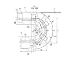
図11は前記方向転換路45の内部を示す拡大図である。前記外周曲面43は、前記インナプレート80の表面上の点Pを円弧中心とする単一円弧状に形成されており、前記ボール5はこの外周曲面43に沿って方向転換路45内を円弧状に移動する。ここで、前記負荷転動体通路31を転走するボール5の転走方向を基準とした場合、前記負荷転動体通路31及び転動体戻し通路32から等距離で離れた位置S(以下、「方向転換路の中央部S」という)では前記ボール5の転走方向が90°変化した状態となる。また、前記転動体戻し通路32を転走するボール5の転走方向は180°変化した状態となる。尚、図11では、方向転換路45内での連結体6の軌道を理解しやすくするため、方向転換路45内のボール5を一点鎖線で描いている。
FIG. 11 is an enlarged view showing the inside of the
これに対し、前述したように連結体6のベルト部材61はスペーサ60との結合部位では撓みにくく、互いに隣接するスペーサ60の間において撓み易くなっている。このため、前記方向転換路内ではボールの移動経路に沿って滑らかな円弧状に湾曲するのではなく、部分的な屈曲を伴って擬似的な円弧状に湾曲することになる。特に、図3に示すように、連結体6のベルト部材61がボール5の中心に対して変位してスペーサ60と結合されており、しかも図11に示すように当該ベルト部材61がボール5の中心よりも無限循環路の内側に存在している場合には、前記方向転換路45内におけるベルト部材61の部分的な屈曲が顕著に発生する。
On the other hand, as described above, the
このため、仮に前記案内溝46を構成する前記外周側案内面44が前記外周曲面43と同一の曲率中心で且つ一定の曲率半径で円弧状に形成されている場合、ベルト部材61の部分的な屈曲部位が前記外周側案内面44と強く干渉してしまう可能性がある。このベルト部材61と外周側案内面44の干渉は、前記方向転換路45の中央部Sよりも、ボールの進行方向が90度変化する過程、すなわち、前記負荷転動体通路31又は転動体戻し通路32から前記方向転換路45の中央部Sに至るまでの経路(以下、「転換経路」という)内で顕著に発生する。
Therefore, if the outer
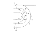
この点に鑑み本発明を適用した運動案内装置では、図12に示すように、前記方向転換路45における案内溝46の溝幅が、前記負荷転動体通路31の案内溝88との連結部位から前記転動体戻し通路32の案内溝91との連結部位にかけて連続的に変化している。ここで、前記案内溝46の溝幅とは、互いに対向する前記外周側案内面44と内周側案内面87との距離である。
In view of this point, in the motion guide device to which the present invention is applied, as shown in FIG. 12, the groove width of the
また、前記案内溝46の溝幅は、前記負荷転動体通路31の案内溝88との連結部位又は前記転動体戻し通路32の案内溝91との連結部位における溝幅をW1、前記方向転換路45の中央部Sにおける溝幅をW2、前記転換経路の途上における溝幅をW3とした場合、W3がW1及びW2よりも大きくなるように設定されている。
Further, the groove width of the
すなわち、本発明の運動案内装置では、前記案内溝46の溝幅は前記転換経路の途上で最大となるように設定されており、例えば、連結体6が前記負荷転動体通路31から前記方向転換路45へ進入して、当該方向転換路の中央部Sに到達するまでの間に、当該溝幅は徐々に増大した後に徐々に減少に転じるようになっている。
That is, in the motion guide device according to the present invention, the groove width of the
このように溝幅が前記方向転換路45内におけるベルト部材61の実際の形状に鑑みて最適化された案内溝46を実現するため、本実施形態では互いに対向して当該案内溝46を構成する前記外周側案内面44及び内周側案内面87に対して以下の形状を与えている。尚、以下に示す外周側案内面44及び内周側案内面87の形状例はあくまで一例であり、前述の案内溝46を実現させるための外周側案内面44及び内周側案内面87の形状はこれに限定されるものではない。
Thus, in order to implement | achieve the
図11に示すように、本実施形態では、前記案内溝46を構成する内周側案内面87が一定の曲率半径で滑らかな円弧状に形成されており、その曲率中心はボール5を案内している外周曲面43の曲率中心Pと合致している。これに対して、前記外周側案内面44は、前記負荷転動体通路31内に形成された案内溝91又は転動体戻し通路32内に形成された案内溝88と連続する一対の直線部44aと、これら一対の直線部44aを連結する転換部44bとを備えている。一対の直線部44aと転換部44bは滑らかに連続している。各直線部44aは前記負荷転動体通路31又は転動体戻し通路32内を転走するボール5の転走方向に合致しており、前記ベルト部材61を前記移動ブロック2の移動に沿って案内する。
As shown in FIG. 11, in this embodiment, the inner
前記転換部44bは中心をQに設定した半楕円形に形成されており、かかる転換部44bの形状は前記内周側案内面87の形状と異なる。この半楕円形の中心Qは前記内周側案内面87の曲率中心Pと方向転換路の中央部Sとを結んだ線分上に位置し、前記曲率中心Pと方向転換路45の内周曲面86の間に位置している。また、前記転換部44bをなす半楕円形の長軸は、当該転換部と一対の直線部44aとの連結点L1、L2を結ぶ長さLの線分であり、この線分上に前記半楕円形の中心Qが存在する。一方、前記転換部44bをなす半楕円形の短軸は、前記方向転換路45の中央部Sに対応する前記転換部44bの頂点をS’とした場合、この頂点S’と前記中心Qを結ぶ長さMの線分であり、この線分は移動ブロック2の移動方向と合致している。
The
このように前記案内溝46を構成する内周側案内面87を一定曲率半径の円弧状に形成する一方、外周側案内面44を直線部44a及び半楕円形の転換部44bからなる複合形状に形成することにより、当該案内溝46の溝幅は前記転換経路途上で最大となり、W3をW1及びW2に対して大きく設定することが可能となる。
In this way, the inner
ここで、仮に前記転換部44bを半楕円形ではなく、一定の曲率半径の円弧状に形成し、その曲率中心を前述した半楕円形の中心Qに合致させた場合、前記案内溝46の溝幅は前記負荷転動体通路31又は転動体戻し通路32との連結端から方向転換路45の中央部Sにかけて徐々に広くなり、中央部Sで最大となる。従って、前記転換部44bを一定の曲率半径の円弧状に形成したのでは、本発明の案内溝46の設定を実現することはできない。
Here, if the converting
そして、このような本実施形態の運動案内装置によれば、前記方向転換路45における連結体6の案内溝46の溝幅が前記転換経路の途上で最大となるように設定した結果、前記連結体のベルト部材が案内溝内で部分的に屈曲しながら擬似的な円弧状に湾曲したとしても、当該ベルト部材61が前記案内溝46を構成する外周側案内面44と強く干渉するのを防止することが可能となる。ひいては、前記方向転換路45内におけるベルト部材61と前記外周側案内面44との干渉を防止することができる分、前記無限循環路内におけるボール5の循環を円滑にすることができ、もって軌道レール1に対する移動ブロック2の移動を円滑にすることが可能となる。
And according to such a motion guide device of this embodiment, as a result of setting the groove width of the
また、前記方向転換路45の案内溝46に対して前述のような溝幅を与えるに際し、当該案内溝46を構成する外周側案内面44の形状としては種々のものが考えられる。しかし、本実施形態の運動案内装置のように、前記外周側案内面44を直線部44aと転換部44bとから構成し、しかも転換部44bを半楕円形に形成すれば、当該外周側案内面を有するエンドプレートの成形が容易となり、これにより運動案内装置全体の生産コストの低減化を図ることが可能となる。
Further, when the groove width as described above is given to the
一方、図6に示すように、前記無限循環路内で向かい合った連結体6の端部6a、6bとの間にはボール5が介在しておらず、各端部6a、6bはボール5に追従して方向転換路45内を循環するわけではない。このため、前記端部6a,6bが方向転換路内に存在する場合であっても、ベルト部材61は各端部6a、6bとこれに隣接するスペーサ60との間では屈曲することなく直線状に伸展する傾向にある。このため、各端部6a、6bは方向転換路45に進入してその中央部Sへと進行する際に、前記外周側案内面44に対して過度に干渉する可能性がある。
On the other hand, as shown in FIG. 6, the
しかし、既に説明してきたように、本実施形態の運動案内装置では案内溝46の溝幅が転換経路の途上で最大となるように設定されているので、前記転換経路の途上で最大となった溝幅は方向転換路の中央部Sに接近するにつれて徐々に減少していく。このため、各端部6a、6bを前記軌道レール1のボール転走溝11に対して垂直な方向に近い状態で前記中央部Sへと進入させることが可能となる。これにより、前記中央部Sに形成された外周側案内面44に対する各端部6a、6bの接触角度を小さくすることができる。その結果、前記外周側案内面44に対する各端部6a、6bの過度な干渉を防ぐことが可能となる。
However, as already explained, in the motion guide device of the present embodiment, the groove width of the
以上説明してきた本発明の運動案内装置では、ボール5を保持した連結体6が方向転換路45を通過する際に、主に、前記連結体6のベルト部材61が案内溝46を構成する外周側案内面44と干渉する場合を想定した。このような場面は、前記負荷転動体通路31を転走するボール5が連結体6に対してこれを方向転換路へ押し込む方向の力を作用させている際に発生し易い。しかし、無限循環路内における連結体6の端部の位置によっては、前記負荷転動体通路31を転走するボール5が連結体6に対してこれを方向転換路45から引き抜く方向の力を作用させている場合もあり、この場合には前記連結体6のベルト部材61が案内溝46を構成する内周側案内面87と干渉することが想定される。
In the motion guide apparatus of the present invention described above, when the connecting
前述の実施形態に係る運動案内装置では、前記案内溝46を構成する内周側案内面87が曲率中心をPとした一定の曲率半径の円弧状に形成されているが、前記ベルト部材61と内周側案内面87との干渉を考慮するならば、前記ベルト部材61の循環軌道に対応して内周側案内面87の形状を適宜設計変更することが好ましい。但し、前記方向転換路45内におけるベルト部材61の屈曲を考慮すると、前記案内溝46の溝幅は前記負荷転動体通路又は転動体戻し通路との連結端から当該方向転換路の中央部Sに至るまでの転換経路途上で最大となり、且つ、前記連結端における溝幅及び前記中央部における溝幅は、前記経路途上における溝幅の最大値よりも小さく設定されていることが前提となる。
In the motion guide apparatus according to the above-described embodiment, the inner
尚、上記実施形態では転動体としてボールを用いた例を説明したが、転動体はボールに限られるものではなく、ローラを使用しても良い。その場合、転動体の転走面の断面形状は使用するローラの形状に応じ、ボールの場合と同様な曲面状の転走溝としても良いし、単なる平面状の転走面としても良い。 In the above embodiment, an example in which a ball is used as a rolling element has been described. However, the rolling element is not limited to a ball, and a roller may be used. In that case, the cross-sectional shape of the rolling surface of the rolling element may be a curved rolling groove similar to the case of the ball, or may be a simple planar rolling surface, depending on the shape of the roller used.
また、上記実施形態では軌道レール1が直線状に形成されており、直線案内装置に関するものとなっているが、本発明はボールの無限循環路を備える運動案内装置であれば例えば軌道レール1が曲線状に形成された曲線案内装置にも適用することが可能である。 In the above embodiment, the track rail 1 is formed in a straight line and relates to a linear guide device. However, if the present invention is a motion guide device having an infinite circulation path for balls, for example, the track rail 1 is provided. The present invention can also be applied to a curved guide device formed in a curved shape.
1…軌道レール、2…移動ブロック、5…ボール(転動体)、6…連結体、31…負荷転動体通路、32…転動体戻し通路、44…外周側案内面、45…方向転換路、60…スペーサ、61…ベルト部材、46,88,91…案内溝、87…内周側案内面、 DESCRIPTION OF SYMBOLS 1 ... Track rail, 2 ... Moving block, 5 ... Ball (rolling element), 6 ... Connection body, 31 ... Load rolling element path, 32 ... Rolling element return path, 44 ... Outer peripheral side guide surface, 45 ... Direction change path, 60 ... spacer, 61 ... belt member, 46, 88, 91 ... guide groove, 87 ... inner peripheral side guide surface,
Claims (3)
前記無限循環路は、前記転動体が軌道レールとの間で荷重を負荷しながら転走する負荷転動体通路と、この負荷転動体通路と平行な転動体戻し通路と、前記負荷転動体通路と転動体戻し通路とを繋ぐ方向転換路とを備え、
前記無限循環路内に配列された複数の転動体は、互いに隣接する転動体の間に配置されるスペーサ及び各スペーサを連結するベルト部材を備えた連結体によって保持され、
前記無限循環路内には前記連結体のベルト部材を転動体の循環方向に沿って案内する案内溝が形成され、
前記方向転換路内に形成された案内溝は外周側案内面とこれに対向する内周側案内面を有し、これら外周側案内面及び内周側案内面は夫々が滑らかに連続し、
前記方向転換路内に形成された案内溝の溝幅は、前記負荷転動体通路又は転動体戻し通路との連結端から当該方向転換路の中央部に至るまでの経路途上で最大となり、且つ、
前記連結端における溝幅及び前記中央部における溝幅は、前記経路途上における溝幅の最大値よりも小さく設定されていることを特徴とする運動案内装置。 A track rail on which the rolling elements roll along the longitudinal direction, and is assembled to the track rail via a number of rolling elements and has an infinite circulation path for the rolling elements, and is movable along the track rail. With blocks,
The infinite circulation path includes a rolling element passage in which the rolling element rolls while applying a load between the rolling element, a rolling element return path parallel to the loaded rolling element path, and the load rolling element path. A direction change path connecting the rolling element return path,
The plurality of rolling elements arranged in the endless circulation path are held by a coupling body including a spacer disposed between the rolling elements adjacent to each other and a belt member coupling the spacers,
A guide groove for guiding the belt member of the coupling body along the circulation direction of the rolling element is formed in the endless circulation path,
The guide groove formed in the direction change path has an outer peripheral side guide surface and an inner peripheral side guide surface opposed to the outer peripheral side guide surface, and each of the outer peripheral side guide surface and the inner peripheral side guide surface is smoothly continuous.
The groove width of the guide groove formed in the direction change path is maximized on the route from the connecting end with the load rolling element passage or the rolling element return path to the center of the direction change path, and
The motion guide device characterized in that the groove width at the connecting end and the groove width at the central portion are set to be smaller than the maximum value of the groove width in the course of the path.
Priority Applications (6)
| Application Number | Priority Date | Filing Date | Title |
|---|---|---|---|
| JP2013007113A JP5726922B2 (en) | 2013-01-18 | 2013-01-18 | Exercise guidance device |
| US14/758,840 US9458883B2 (en) | 2013-01-18 | 2013-11-12 | Motion-guiding device |
| PCT/JP2013/080554 WO2014112190A1 (en) | 2013-01-18 | 2013-11-12 | Motion-guiding device |
| CN201380068769.0A CN104884826B (en) | 2013-01-18 | 2013-11-12 | Motion guide device |
| DE112013006453.7T DE112013006453B4 (en) | 2013-01-18 | 2013-11-12 | Movement guidance device |
| TW102142838A TWI557335B (en) | 2013-01-18 | 2013-11-25 | Movement guide device |
Applications Claiming Priority (1)
| Application Number | Priority Date | Filing Date | Title |
|---|---|---|---|
| JP2013007113A JP5726922B2 (en) | 2013-01-18 | 2013-01-18 | Exercise guidance device |
Publications (2)
| Publication Number | Publication Date |
|---|---|
| JP2014137125A true JP2014137125A (en) | 2014-07-28 |
| JP5726922B2 JP5726922B2 (en) | 2015-06-03 |
Family
ID=51209302
Family Applications (1)
| Application Number | Title | Priority Date | Filing Date |
|---|---|---|---|
| JP2013007113A Active JP5726922B2 (en) | 2013-01-18 | 2013-01-18 | Exercise guidance device |
Country Status (6)
| Country | Link |
|---|---|
| US (1) | US9458883B2 (en) |
| JP (1) | JP5726922B2 (en) |
| CN (1) | CN104884826B (en) |
| DE (1) | DE112013006453B4 (en) |
| TW (1) | TWI557335B (en) |
| WO (1) | WO2014112190A1 (en) |
Cited By (2)
| Publication number | Priority date | Publication date | Assignee | Title |
|---|---|---|---|---|
| JP3217850U (en) * | 2018-06-22 | 2018-09-06 | 上銀科技股▲分▼有限公司 | Linear guide with lubricating oil passage |
| WO2020209001A1 (en) * | 2019-04-08 | 2020-10-15 | Thk株式会社 | Motion guiding device |
Families Citing this family (7)
| Publication number | Priority date | Publication date | Assignee | Title |
|---|---|---|---|---|
| US10294993B2 (en) * | 2013-03-27 | 2019-05-21 | Nsk Ltd. | Lubricant supply device for linear guide apparatus, and linear guide apparatus |
| JP6385384B2 (en) * | 2016-04-11 | 2018-09-05 | Thk株式会社 | Rolling guide device |
| JP1575127S (en) * | 2016-11-16 | 2017-05-01 | ||
| JP1575891S (en) * | 2016-12-20 | 2017-05-08 | ||
| JP1586244S (en) * | 2017-05-09 | 2020-09-14 | ||
| CN110081079A (en) * | 2019-04-09 | 2019-08-02 | 浙江非攻机械有限公司 | Straight-line guide rail slide block and linear motion guidance device with it |
| CN110131311A (en) * | 2019-04-09 | 2019-08-16 | 浙江非攻机械有限公司 | Straight-line guide rail slide block and linear motion guidance device |
Citations (5)
| Publication number | Priority date | Publication date | Assignee | Title |
|---|---|---|---|---|
| JP2004293783A (en) * | 2003-03-13 | 2004-10-21 | Nsk Ltd | Linear motion guide bearing device |
| JP2005133842A (en) * | 2003-10-30 | 2005-05-26 | Nsk Ltd | Linear motion guide bearing device |
| JP2007092899A (en) * | 2005-09-29 | 2007-04-12 | Nsk Ltd | Rolling body accommodation belt for linear motion guide device and linear motion guide device |
| JP2009127740A (en) * | 2007-11-22 | 2009-06-11 | Nsk Ltd | Linear motion guidance device |
| JP2010031931A (en) * | 2008-07-28 | 2010-02-12 | Shangyin Sci & Technol Co Ltd | Circular flow structure for linear guide way |
Family Cites Families (12)
| Publication number | Priority date | Publication date | Assignee | Title |
|---|---|---|---|---|
| FR1331533A (en) * | 1962-05-24 | 1963-07-05 | Guiding device | |
| US3964802A (en) * | 1972-12-21 | 1976-06-22 | Nadella | Bearing for rectilinear motion |
| JPS58155426U (en) * | 1982-04-14 | 1983-10-17 | 日本精工株式会社 | track guide bearing |
| JP3243415B2 (en) * | 1996-06-27 | 2002-01-07 | テイエチケー株式会社 | Sliding guide device and its end rolling element chain |
| JP2000120674A (en) * | 1998-10-12 | 2000-04-25 | Nsk Ltd | Linear motion guide device |
| JP2001182745A (en) * | 1999-12-27 | 2001-07-06 | Nsk Ltd | Linear guide bearing |
| JP3420204B2 (en) * | 2000-11-17 | 2003-06-23 | Thk株式会社 | Guidance device |
| EP1457693A2 (en) * | 2003-03-13 | 2004-09-15 | NSK Ltd., | Linear guide apparatus |
| EP1801435A3 (en) * | 2004-11-11 | 2008-05-14 | NSK Ltd. | Linear guide device and rolling element accomodating belt for the same |
| US7798718B2 (en) | 2005-09-29 | 2010-09-21 | Nsk Ltd. | Rolling element accommodating belt for linear guide apparatus and linear guide apparatus |
| JP2007333147A (en) * | 2006-06-16 | 2007-12-27 | Nsk Ltd | End cap and linear motion guide bearing device including the same |
| JP5909866B2 (en) * | 2011-04-20 | 2016-04-27 | 日本精工株式会社 | Return guide and linear motion guide bearing device having the same |
-
2013
- 2013-01-18 JP JP2013007113A patent/JP5726922B2/en active Active
- 2013-11-12 CN CN201380068769.0A patent/CN104884826B/en active Active
- 2013-11-12 WO PCT/JP2013/080554 patent/WO2014112190A1/en not_active Ceased
- 2013-11-12 DE DE112013006453.7T patent/DE112013006453B4/en active Active
- 2013-11-12 US US14/758,840 patent/US9458883B2/en active Active
- 2013-11-25 TW TW102142838A patent/TWI557335B/en active
Patent Citations (5)
| Publication number | Priority date | Publication date | Assignee | Title |
|---|---|---|---|---|
| JP2004293783A (en) * | 2003-03-13 | 2004-10-21 | Nsk Ltd | Linear motion guide bearing device |
| JP2005133842A (en) * | 2003-10-30 | 2005-05-26 | Nsk Ltd | Linear motion guide bearing device |
| JP2007092899A (en) * | 2005-09-29 | 2007-04-12 | Nsk Ltd | Rolling body accommodation belt for linear motion guide device and linear motion guide device |
| JP2009127740A (en) * | 2007-11-22 | 2009-06-11 | Nsk Ltd | Linear motion guidance device |
| JP2010031931A (en) * | 2008-07-28 | 2010-02-12 | Shangyin Sci & Technol Co Ltd | Circular flow structure for linear guide way |
Cited By (7)
| Publication number | Priority date | Publication date | Assignee | Title |
|---|---|---|---|---|
| JP3217850U (en) * | 2018-06-22 | 2018-09-06 | 上銀科技股▲分▼有限公司 | Linear guide with lubricating oil passage |
| WO2020209001A1 (en) * | 2019-04-08 | 2020-10-15 | Thk株式会社 | Motion guiding device |
| JP2020172946A (en) * | 2019-04-08 | 2020-10-22 | Thk株式会社 | Motion guide device |
| CN113661332A (en) * | 2019-04-08 | 2021-11-16 | Thk株式会社 | Motion guide device |
| JP7299052B2 (en) | 2019-04-08 | 2023-06-27 | Thk株式会社 | Exercise guide device |
| US11767882B2 (en) | 2019-04-08 | 2023-09-26 | Thk Co., Ltd. | Motion guide apparatus |
| CN113661332B (en) * | 2019-04-08 | 2024-04-23 | Thk株式会社 | Motion guidance device |
Also Published As
| Publication number | Publication date |
|---|---|
| US9458883B2 (en) | 2016-10-04 |
| JP5726922B2 (en) | 2015-06-03 |
| WO2014112190A1 (en) | 2014-07-24 |
| DE112013006453B4 (en) | 2024-03-14 |
| TW201430231A (en) | 2014-08-01 |
| US20150337899A1 (en) | 2015-11-26 |
| CN104884826A (en) | 2015-09-02 |
| DE112013006453T5 (en) | 2015-09-24 |
| CN104884826B (en) | 2017-03-08 |
| TWI557335B (en) | 2016-11-11 |
Similar Documents
| Publication | Publication Date | Title |
|---|---|---|
| JP5726922B2 (en) | Exercise guidance device | |
| TWI700441B (en) | Rolling guide | |
| JP6185752B2 (en) | Exercise guidance device | |
| JP5695248B2 (en) | Exercise guidance device | |
| JP6559176B2 (en) | Exercise guidance device | |
| JP5596176B2 (en) | Exercise guidance device | |
| JP5265793B1 (en) | Rolling guide device | |
| JP5785570B2 (en) | Exercise guidance device | |
| JP5721769B2 (en) | Rolling guide device | |
| KR101217320B1 (en) | Movement guiding device | |
| JP2013002625A (en) | Rolling guide device | |
| JP5872398B2 (en) | Rolling guide device | |
| CN111065831B (en) | motion guide | |
| JP5063552B2 (en) | Exercise guidance device | |
| JP2012082879A (en) | Motion guide device | |
| JP7079173B2 (en) | Exercise guidance device | |
| JP4556830B2 (en) | Rolling body accommodation belt for linear motion guide device and linear motion guide device | |
| JP2008121861A (en) | Ball housing member and linear motion guide device | |
| JP4600340B2 (en) | Rolling element housing belt and linear motion guide device | |
| JP2012087904A (en) | Ball connection belt and motion guide device using the same | |
| JP2008121862A (en) | Linear motion guide device | |
| JP2006300164A (en) | Linear guide device | |
| JP2013204623A (en) | Rolling guide device |
Legal Events
| Date | Code | Title | Description |
|---|---|---|---|
| A621 | Written request for application examination |
Free format text: JAPANESE INTERMEDIATE CODE: A621 Effective date: 20140918 |
|
| A871 | Explanation of circumstances concerning accelerated examination |
Free format text: JAPANESE INTERMEDIATE CODE: A871 Effective date: 20140918 |
|
| A975 | Report on accelerated examination |
Free format text: JAPANESE INTERMEDIATE CODE: A971005 Effective date: 20141001 |
|
| A131 | Notification of reasons for refusal |
Free format text: JAPANESE INTERMEDIATE CODE: A131 Effective date: 20141118 |
|
| A521 | Request for written amendment filed |
Free format text: JAPANESE INTERMEDIATE CODE: A523 Effective date: 20150109 |
|
| TRDD | Decision of grant or rejection written | ||
| A01 | Written decision to grant a patent or to grant a registration (utility model) |
Free format text: JAPANESE INTERMEDIATE CODE: A01 Effective date: 20150331 |
|
| A61 | First payment of annual fees (during grant procedure) |
Free format text: JAPANESE INTERMEDIATE CODE: A61 Effective date: 20150401 |
|
| R150 | Certificate of patent or registration of utility model |
Ref document number: 5726922 Country of ref document: JP Free format text: JAPANESE INTERMEDIATE CODE: R150 |
|
| R250 | Receipt of annual fees |
Free format text: JAPANESE INTERMEDIATE CODE: R250 |
|
| R250 | Receipt of annual fees |
Free format text: JAPANESE INTERMEDIATE CODE: R250 |
|
| R250 | Receipt of annual fees |
Free format text: JAPANESE INTERMEDIATE CODE: R250 |
|
| R250 | Receipt of annual fees |
Free format text: JAPANESE INTERMEDIATE CODE: R250 |
|
| R250 | Receipt of annual fees |
Free format text: JAPANESE INTERMEDIATE CODE: R250 |
|
| R250 | Receipt of annual fees |
Free format text: JAPANESE INTERMEDIATE CODE: R250 |
|
| R250 | Receipt of annual fees |
Free format text: JAPANESE INTERMEDIATE CODE: R250 |
|
| R250 | Receipt of annual fees |
Free format text: JAPANESE INTERMEDIATE CODE: R250 |
|
| R250 | Receipt of annual fees |
Free format text: JAPANESE INTERMEDIATE CODE: R250 |