JP2014127530A - Damping member for control apparatus and earthquake-resistant structure of control apparatus - Google Patents

Damping member for control apparatus and earthquake-resistant structure of control apparatus Download PDF

Info

Publication number
JP2014127530A
JP2014127530A JP2012281777A JP2012281777A JP2014127530A JP 2014127530 A JP2014127530 A JP 2014127530A JP 2012281777 A JP2012281777 A JP 2012281777A JP 2012281777 A JP2012281777 A JP 2012281777A JP 2014127530 A JP2014127530 A JP 2014127530A
Authority
JP
Japan
Prior art keywords
damping member
control device
control devices
main body
control
Prior art date
Legal status (The legal status is an assumption and is not a legal conclusion. Google has not performed a legal analysis and makes no representation as to the accuracy of the status listed.)
Granted
Application number
JP2012281777A
Other languages
Japanese (ja)
Other versions
JP6139128B2 (en
Inventor
Takaki Ishikawa
敬樹 石川
Satoru Mori
悟 毛利
Takahiro Sagane
高寛 相根
Yasuhiko Fukuyama
泰彦 福山
Current Assignee (The listed assignees may be inaccurate. Google has not performed a legal analysis and makes no representation or warranty as to the accuracy of the list.)
Mitsubishi Heavy Industries Ltd
Original Assignee
Mitsubishi Heavy Industries Ltd
Priority date (The priority date is an assumption and is not a legal conclusion. Google has not performed a legal analysis and makes no representation as to the accuracy of the date listed.)
Filing date
Publication date
Application filed by Mitsubishi Heavy Industries Ltd filed Critical Mitsubishi Heavy Industries Ltd
Priority to JP2012281777A priority Critical patent/JP6139128B2/en
Publication of JP2014127530A publication Critical patent/JP2014127530A/en
Application granted granted Critical
Publication of JP6139128B2 publication Critical patent/JP6139128B2/en
Active legal-status Critical Current
Anticipated expiration legal-status Critical

Links

Images

Abstract

PROBLEM TO BE SOLVED: To suppress vibration of a control apparatus properly with a simple configuration, in a damping member for a control apparatus and an earthquake-resistant structure of the control apparatus.SOLUTION: A damping member 11 for control apparatus is constituted of a damping member body 12 arranged tightly on the sides (first surfaces) A1, B1 of two control apparatus A, B facing each other, and a damping member auxiliary body 13 arranged tightly on the upper sides (second surfaces) of two control apparatus A, B not facing each other, the damping member auxiliary body 13 being coupled with the damping member body 12.

Description

本発明は、各種の装置を制御する制御機器の振動を抑制する制御機器用制振部材に関するものである。   The present invention relates to a damping member for a control device that suppresses vibration of a control device that controls various devices.

各種のプラントや工場などでは、装置を制御するための制御装置が配置されており、この制御装置は、一般に、制御室などに設置されている。例えば、原子力発電プラントなどでは、中央管理室に各種の制御装置が設置され、オペレータは、操作装置を用いてこの制御装置により原子力発電設備を制御している。   In various plants and factories, a control device for controlling the device is arranged, and this control device is generally installed in a control room or the like. For example, in a nuclear power plant or the like, various control devices are installed in a central management room, and an operator uses a control device to control nuclear power generation equipment using the control device.

このような原子力発電プラントでは、十分な耐震性を確保する必要がある。この場合、原子力発電設備だけではなく、中央管理室の制御装置についても、高い耐震性を確保しなければならない。制御機器の耐震性を確保するものものとしては、例えば、下記特許文献1に記載されたものがある。特許文献1に記載された制御装置の実装構造は、凸状の押し出し部を設けることで、振動を抑制するようにしている。   In such a nuclear power plant, it is necessary to ensure sufficient earthquake resistance. In this case, high earthquake resistance must be ensured not only for the nuclear power generation equipment but also for the control device in the central control room. As what secures the earthquake resistance of a control apparatus, there exists a thing described in the following patent document 1, for example. The mounting structure of the control device described in Patent Document 1 suppresses vibration by providing a convex pushing portion.

特開2011−035208号公報JP 2011-035208 A

制御装置は、各種の制御機器が所定間隔をもって配置されているのが一般的であり、凸状の押し出し部を設けた構造では、複数の制御機器の振動を抑制することは困難であり、また、構造が複雑化して製造コストが増加してしまう。更に、凸状の押し出し部が劣化した場合には、交換する必要があるが、このような従来の構成にでは、交換コストが増加してしまうという問題がある。   In the control device, various control devices are generally arranged at a predetermined interval, and with a structure provided with a convex extruded portion, it is difficult to suppress vibrations of a plurality of control devices. The structure becomes complicated and the manufacturing cost increases. Further, when the convex extruded portion deteriorates, it needs to be replaced. However, such a conventional configuration has a problem that the replacement cost increases.

本発明は、上述した課題を解決するものであり、簡単な構成で制御機器の振動を適正に抑制可能とする制御機器用制振部材及び制御機器の耐震構造を提供することを目的とする。   The present invention solves the above-described problems, and an object thereof is to provide a damping member for a control device and an earthquake-resistant structure of the control device that can appropriately suppress vibrations of the control device with a simple configuration.

上記の目的を達成するための本発明の制御機器用制振部材は、隣接する2つの制御機器の間に装着されて振動を抑制可能な制御機器用制振部材であって、前記2つの制御機器の対向する第1面にそれぞれ密着して配置される制振部材本体と、前記2つの制御機器の対向しない第2面にそれぞれ沿って配置されると共に前記制振部材本体に連結される制振部材補助体と、を有することを特徴とするものである。   In order to achieve the above object, a vibration damping member for a control device according to the present invention is a vibration damping member for a control device that is mounted between two adjacent control devices and is capable of suppressing vibrations. A damping member main body disposed in close contact with the opposing first surface of the device, and a damping member main body disposed along the non-opposing second surface of the two control devices and coupled to the damping member main body. And a vibration member auxiliary body.

従って、2つの制御機器は、対向する第1面の間に制振部材本体が密着して配置されると共に、対向しない第2面に制振部材補助体が沿って配置されることで、地震などにより振動が作用しても、制御機器同士が接触することなく、簡単な構成で制御機器の振動を適正に抑制可能とすることができ、耐震性を向上することができる。また、2つの制御機器に対して制振部材本体と制振部材補助体を配置することで、制御機器用制振部材の交換を容易に行うことができる。   Accordingly, the two control devices are arranged such that the vibration damping member main body is closely attached between the first surfaces facing each other, and the vibration damping member auxiliary body is disposed along the second surface not opposed to the earthquake. Even if the vibration acts due to the above, it is possible to appropriately suppress the vibration of the control device with a simple configuration without contact between the control devices, and it is possible to improve the earthquake resistance. In addition, by arranging the damping member main body and the damping member auxiliary body for the two control devices, the damping member for the control device can be easily replaced.

本発明の制御機器用制振部材では、前記制振部材本体と前記制振部材補助体は、ほぼ直交する方向に連結されることを特徴としている。   In the damping member for a control device according to the present invention, the damping member main body and the damping member auxiliary body are connected in a substantially orthogonal direction.

従って、制振部材本体と制振部材補助体が直交に連結されることで、一般的な矩形状をなす制御機器の外面に対して適正に密着することができる。   Therefore, the vibration damping member main body and the vibration damping member auxiliary body are orthogonally connected to each other so that the vibration member main body and the vibration damping member auxiliary body can be properly adhered to the outer surface of the control device having a general rectangular shape.

本発明の制御機器用制振部材では、前記制振部材補助体が複数設けられることを特徴としている。   The damping member for a control device according to the present invention is characterized in that a plurality of the damping member auxiliary bodies are provided.

従って、制振部材補助体が複数設けられることで、各制振部材補助体が制御機器の対向しない複数の第2面に対して密着することとなり、制御機器の振動を適正に抑制することができる。   Therefore, by providing a plurality of damping member auxiliary bodies, each damping member auxiliary body comes into close contact with a plurality of second surfaces that are not opposed to the control device, and the vibration of the control device can be appropriately suppressed. it can.

本発明の制御機器用制振部材では、前記制振部材本体が複数設けられることを特徴としている。   The damping member for a control device according to the present invention is characterized in that a plurality of the damping member bodies are provided.

従って、制振部材本体が複数設けられることで、所定隙間をもって並設された複数の制御機器の振動を効果的に抑制することができる。   Therefore, by providing a plurality of damping member bodies, it is possible to effectively suppress vibrations of a plurality of control devices arranged in parallel with a predetermined gap.

本発明の制御機器用制振部材では、前記2つの制御機器の間に圧入されて係止可能なくさび部が設けられることを特徴としている。   The damping member for a control device according to the present invention is characterized in that a wedge portion that is press-fitted between the two control devices and can be locked is provided.

従って、くさび部が2つの制御機器の間に圧入されることで、制御部材本体を制御機器に係止することができ、振動発生時における脱落を防止することができる。   Therefore, when the wedge portion is press-fitted between the two control devices, the control member main body can be locked to the control device, and can be prevented from falling off when vibration is generated.

本発明の制御機器用制振部材では、前記くさび部は、前記制振部材本体と前記制振部材補助体の連結部に設けられることを特徴としている。   In the damping member for a control device according to the present invention, the wedge portion is provided at a connection portion between the damping member main body and the damping member auxiliary body.

従って、2つの制御機器における対向する第1面の間に制振部材本体が密着して配置されると共に、対向しない第2面に制振部材補助体が配置されるとき、制振部材本体と制振部材補助体の連結部に設けられたくさび部が2つの制御機器の間に圧入されることとなり、制振部材本体と制振部材補助体の適正な装着位置からのずれを防止することができる。   Therefore, when the vibration damping member main body is disposed in close contact between the first surfaces facing each other in the two control devices, and the vibration damping member auxiliary body is disposed on the second surface not opposed to the vibration control member main body, The wedge part provided at the connecting part of the damping member auxiliary body is press-fitted between the two control devices, and the deviation of the damping member main body and the damping member auxiliary body from the proper mounting position is prevented. Can do.

本発明の制御機器用制振部材では、前記制振部材本体は、その長さまたは幅が調整可能であることを特徴としている。   In the damping member for a control device according to the present invention, the length or width of the damping member body can be adjusted.

従って、制御機器の大きさに応じて制振部材本体の長さや幅を調整することで、専用部材を製造する必要がなくなり、汎用性を向上して製造コストの増加を防止することができる。   Therefore, by adjusting the length and width of the damping member main body according to the size of the control device, there is no need to manufacture a dedicated member, and versatility can be improved and an increase in manufacturing cost can be prevented.

本発明の制御機器用制振部材では、前記2つの制御機器と前記制振部材本体との密着状態を保持する保持部材が設けられることを特徴としている。   The vibration damping member for a control device according to the present invention is characterized in that a holding member that holds a close contact state between the two control devices and the vibration damping member main body is provided.

従って、保持部材により各制御機器と制振部材本体との密着状態を適正に保持されることとなり、信頼性を向上することができる。   Therefore, the close contact state between each control device and the damping member main body is appropriately held by the holding member, and the reliability can be improved.

また、本発明の制御機器の耐震構造は、隣接する2つの制御機器の間に請求項1から8のいずれか一つの前記制振部材が装着されたことを特徴とするとものである。   The earthquake-resistant structure of the control device according to the present invention is characterized in that the damping member according to any one of claims 1 to 8 is mounted between two adjacent control devices.

従って、2つの制御機器は、対向する第1面の間に制振部材本体が密着して配置されると共に、対向しない第2面に制振部材補助体が密着して配置されることとなり、簡単な構成で制御機器の振動を適正に抑制可能とするができ、耐震性を向上することができる。   Accordingly, in the two control devices, the vibration damping member main body is disposed in close contact between the opposing first surfaces, and the vibration suppression member auxiliary body is disposed in close contact with the second surface that is not opposed, The vibration of the control device can be appropriately suppressed with a simple configuration, and the earthquake resistance can be improved.

本発明の制御機器用制振部材及び制御機器の耐震構造によれば、2つの制御機器の対向する第1面にそれぞれ密着して配置される制振部材本体と、2つの制御機器の対向しない第2面にそれぞれ密着して配置されると共に前記制振部材本体に連結される制振部材補助体とを設けるので、簡単な構成で制御機器の振動を適正に抑制可能とするができ、耐震性を向上することができる。   According to the vibration control member for a control device and the earthquake-resistant structure of the control device of the present invention, the vibration control member main body disposed in close contact with the opposing first surfaces of the two control devices and the two control devices do not face each other. Since the vibration damping member auxiliary body connected to the vibration damping member main body and disposed in close contact with the second surface is provided, the vibration of the control device can be appropriately suppressed with a simple configuration, Can be improved.

図1は、本発明の実施例1に係る制御機器用制振部材を表す概略図である。FIG. 1 is a schematic diagram illustrating a vibration damping member for a control device according to a first embodiment of the present invention. 図2は、本発明の実施例2に係る制御機器用制振部材を表す概略図である。FIG. 2 is a schematic diagram illustrating a vibration damping member for a control device according to a second embodiment of the present invention. 図3は、本発明の実施例3に係る制御機器用制振部材を表す概略図である。FIG. 3 is a schematic diagram illustrating a vibration damping member for a control device according to a third embodiment of the present invention. 図4は、本発明の実施例4に係る制御機器用制振部材を表す概略図である。FIG. 4 is a schematic diagram illustrating a vibration damping member for a control device according to a fourth embodiment of the present invention. 図5は、本発明の実施例5に係る制御機器用制振部材を表す概略図である。FIG. 5 is a schematic diagram illustrating a vibration damping member for a control device according to a fifth embodiment of the present invention. 図6は、実施例5の制御機器用制振部材の変形例を表す概略図である。FIG. 6 is a schematic diagram illustrating a modified example of the damping member for a control device according to the fifth embodiment. 図7は、本発明の実施例6に係る制御機器用制振部材を表す概略図である。FIG. 7 is a schematic diagram illustrating a vibration damping member for a control device according to a sixth embodiment of the present invention. 図8は、本発明の実施例7に係る制御機器用制振部材を表す概略図である。FIG. 8 is a schematic diagram illustrating a vibration damping member for a control device according to a seventh embodiment of the present invention. 図9は、本発明の実施例8に係る制御機器用制振部材を表す概略図である。FIG. 9 is a schematic diagram illustrating a vibration damping member for a control device according to an eighth embodiment of the present invention.

以下に添付図面を参照して、本発明に係る制御機器用制振部材及び制御機器の耐震構造の好適な実施例を詳細に説明する。なお、この実施例により本発明が限定されるものではなく、また、実施例が複数ある場合には、各実施例を組み合わせて構成するものも含むものである。   Exemplary embodiments of a vibration damping member for a control device and an earthquake resistant structure for the control device according to the present invention will be described below in detail with reference to the accompanying drawings. In addition, this invention is not limited by this Example, Moreover, when there exists multiple Example, what comprises combining each Example is also included.

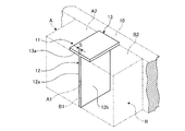
図1は、本発明の実施例1に係る制御機器用制振部材を表す概略図である。   FIG. 1 is a schematic diagram illustrating a vibration damping member for a control device according to a first embodiment of the present invention.

実施例1において、図1に示すように、制御機器用制振部材11は、隣接する2つの制御機器A,Bの間に装着されて振動を抑制可能なものである。この制御機器用制振部材11は、1つの制振部材本体12と、1つの制振部材補助体13が一体に連結されて構成されている。   In the first embodiment, as illustrated in FIG. 1, the control device damping member 11 is mounted between two adjacent control devices A and B and can suppress vibration. This damping member 11 for control equipment is configured by integrally connecting one damping member main body 12 and one damping member auxiliary body 13.

制振部材本体12は、2つの制御機器A,Bにおける対向する第1面としての側面A1,B1にそれぞれ密着して配置されている。制振部材補助体13は、2つの制御機器A,Bの対向しない第2面としての上面A2,B2にそれぞれ沿って密着して配置されている。そして、この制振部材本体12と制振部材補助体13は、ほぼ直交する方向に一体に連結されている。   The damping member main body 12 is disposed in close contact with the side surfaces A1 and B1 as first opposing surfaces of the two control devices A and B, respectively. The damping member auxiliary body 13 is disposed in close contact with the upper surfaces A2 and B2 as the second surfaces of the two control devices A and B that do not face each other. The vibration damping member main body 12 and the vibration damping member auxiliary body 13 are integrally connected in a substantially orthogonal direction.

即ち、2つの制御機器A,Bは、裏面が縦型の基板10に密着し、図示しないボルトなどにより固定されている。この制御機器A,Bは、側面A1,B1同士の間に所定の隙間Sが設けられている。   That is, the two control devices A and B are in close contact with the vertical substrate 10 on the back surface and are fixed by bolts or the like (not shown). In the control devices A and B, a predetermined gap S is provided between the side surfaces A1 and B1.

制御機器用制振部材11は、弾性部材であって、例えば、ゴム、樹脂などにより構成され、金型や押し出し成形により構成することが好ましい。制振部材本体12は、側面12a,12bの表面積が制御機器A,Bの側面A1,B1の表面積(高さと奥行き)とほぼ同様の大きさに設定され、厚さが制御機器A,Bにおける側面A1,B1の隙間Sと同等または若干大きく設定されている。   The control device damping member 11 is an elastic member, and is preferably made of, for example, rubber, resin, or the like, and is preferably made of a mold or extrusion molding. The vibration control member main body 12 is set such that the surface areas of the side surfaces 12a and 12b are substantially the same as the surface area (height and depth) of the side surfaces A1 and B1 of the control devices A and B, and the thickness is the same in the control devices A and B. It is set equal to or slightly larger than the gap S between the side surfaces A1 and B1.

また、制振部材補助体13は、下面13aの幅が制御機器A,Bの上面A2,B2の幅の半分以下の大きさに設定されると共に、奥行きが各上面A2,B2の奥行きと同等の大きさに設定され、厚さが制振部材本体12と同等の大きさに設定されている。   Further, the damping member auxiliary body 13 is set such that the width of the lower surface 13a is not more than half the width of the upper surfaces A2 and B2 of the control devices A and B, and the depth is equal to the depth of the upper surfaces A2 and B2. The thickness is set to a size equivalent to that of the damping member main body 12.

そして、制振部材本体12は、上端面に制振部材補助体13における下面13aの幅方向の中間部が連結されており、縦断面がT字をなすように構成されている。   And the damping member main body 12 is connected to the upper end surface at the intermediate portion in the width direction of the lower surface 13a of the damping member auxiliary body 13, and is configured such that the longitudinal section forms a T-shape.

従って、2つの制御機器A,Bが基板10に固定され、側面A1,B1の間に隙間Sが設けられている状態で、制御機器用制振部材11は、制振部材本体12が2つの制御機器A,Bにおける側面A1,B1の間(隙間S)に挿入される。このとき、制振部材本体12の各側面12a,12bが制御機器A,Bの側面A1,B1に密着する。また、制振部材補助体13は、下面13aが制御機器A,Bの上面A2,B2に密着する。   Therefore, in the state where the two control devices A and B are fixed to the substrate 10 and the gap S is provided between the side surfaces A1 and B1, the control device damping member 11 includes two damping member bodies 12. It is inserted between the side surfaces A1 and B1 (gap S) of the control devices A and B. At this time, the side surfaces 12a and 12b of the damping member main body 12 are in close contact with the side surfaces A1 and B1 of the control devices A and B. Further, the vibration damping member auxiliary body 13 has the lower surface 13a in close contact with the upper surfaces A2 and B2 of the control devices A and B.

その結果、隣接する2つの制御機器A,Bの間に制御機器用制振部材11が装着されることで、実施例1の制御機器の耐震構造が構成されている。この場合、制御機器用制振部材11は、制振部材本体12が2つの制御機器A,Bにおける側面A1,B1の隙間Sに圧入されていることから、脱落が防止されている。   As a result, the control device vibration damping member 11 is mounted between the two adjacent control devices A and B, so that the earthquake resistant structure of the control device of the first embodiment is configured. In this case, the damping member 11 for the control device is prevented from dropping because the damping member body 12 is press-fitted into the gap S between the side surfaces A1 and B1 of the two control devices A and B.

このように実施例1の制御機器用制振部材11にあっては、2つの制御機器A,Bの対向する側面(第1面)A1,B1にそれぞれ密着して配置される制振部材本体12と、2つの制御機器A,Bの対向しない上面(第2面)A2,B2にそれぞれ密着して配置されると共に制振部材本体12に連結される制振部材補助体13とから構成されている。   Thus, in the control device damping member 11 of the first embodiment, the damping member main body disposed in close contact with the opposing side surfaces (first surface) A1 and B1 of the two control devices A and B, respectively. 12 and a damping member auxiliary body 13 disposed in close contact with the non-opposing upper surfaces (second surfaces) A2 and B2 of the two control devices A and B and coupled to the damping member main body 12. ing.

従って、2つの制御機器A,Bは、対向する側面A1,B1の間に制振部材本体12が密着して配置されると共に、対向しない上面A2,B2に制振部材補助体13が密着して配置されることで、地震などにより制御機器A,Bに振動が作用しても、この制御機器A,Bの振動が制御機器用制振部材11により吸収される。そのため、制御機器A,B同士は、互いに接触することはなく、簡単な構成で制御機器A,Bの振動を適正に抑制することができる。また、制御機器用制振部材11は、制御機器A,Bから着脱自在であることから、この制御機器用制振部材11が劣化したときに容易に交換することができると共に、制御機器A,Bの保守点検作業や交換作業などを容易に行うことができる。   Therefore, in the two control devices A and B, the vibration damping member main body 12 is disposed in close contact between the opposed side surfaces A1 and B1, and the vibration damping member auxiliary body 13 is adhered to the upper surfaces A2 and B2 that are not opposed to each other. Therefore, even if vibrations act on the control devices A and B due to an earthquake or the like, the vibrations of the control devices A and B are absorbed by the control device damping member 11. Therefore, the control devices A and B are not in contact with each other, and the vibrations of the control devices A and B can be appropriately suppressed with a simple configuration. Further, since the vibration control member 11 for the control device is detachable from the control devices A and B, it can be easily replaced when the vibration control member 11 for the control device is deteriorated. Maintenance and inspection work and replacement work of B can be easily performed.

実施例1の制御機器用制振部材11では、制振部材本体12と制振部材補助体13をほぼ直交する方向に連結している。制振部材本体12と制振部材補助体13が直交に連結されることで、一般的な矩形状をなす制御機器A,Bの外面に対して適正に密着することができる。   In the vibration damping member 11 for a control device according to the first embodiment, the vibration damping member main body 12 and the vibration damping member auxiliary body 13 are connected in a substantially orthogonal direction. By connecting the damping member main body 12 and the damping member auxiliary body 13 orthogonally, it is possible to properly adhere to the outer surfaces of the control devices A and B having a general rectangular shape.

また、実施例1の制御機器の耐震構造にあっては、隣接する2つの制御機器A,Bの間に制御機器用制振部材11が装着されて構成されている。従って、簡単な構成で制御機器A,Bの振動を適正に抑制可能とすることができ、耐震性を向上することができる。   Moreover, in the seismic structure of the control device of the first embodiment, the control device damping member 11 is mounted between two adjacent control devices A and B. Therefore, the vibrations of the control devices A and B can be appropriately suppressed with a simple configuration, and the earthquake resistance can be improved.

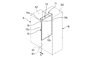
図2は、本発明の実施例2に係る制御機器用制振部材を表す概略図である。   FIG. 2 is a schematic diagram illustrating a vibration damping member for a control device according to a second embodiment of the present invention.

実施例2において、図2に示すように、制御機器用制振部材21は、隣接する3つの制御機器A,B,Cの間に装着されて振動を抑制可能なものである。この制御機器用制振部材21は、1つの制振部材本体22と、2つの制振部材補助体23,24が一体に連結されて構成されている。即ち、実施例2の制御機器用制振部材21は、複数の制振部材補助体23,24が設けられている。   In the second embodiment, as shown in FIG. 2, the control device damping member 21 is mounted between the three adjacent control devices A, B, and C and can suppress vibration. The control device damping member 21 is configured by integrally connecting one damping member body 22 and two damping member auxiliary bodies 23 and 24. That is, the control device damping member 21 of the second embodiment is provided with a plurality of damping member auxiliary bodies 23 and 24.

制振部材本体22は、3つの制御機器A,B,Cにおける対向する第1面としての側面A1,B1,C1にそれぞれ密着して配置されている。制振部材補助体23は、3つの制御機器A,B,Cの対向しない第2面としての上面A2,B2,C2にそれぞれ沿って密着して配置されている。制振部材補助体24は、3つの制御機器A,B,Cの対向しない第2面としての下面A3,B3,C3にそれぞれ沿って密着して配置されている。   The damping member main body 22 is disposed in close contact with the side surfaces A1, B1, and C1 as the first opposing surfaces of the three control devices A, B, and C, respectively. The damping member auxiliary body 23 is disposed in close contact with the upper surfaces A2, B2, and C2 as the second surfaces of the three control devices A, B, and C that do not face each other. The damping member auxiliary body 24 is disposed in close contact with the lower surfaces A3, B3, and C3 as the second surfaces of the three control devices A, B, and C that do not face each other.

そして、この制振部材本体22と制振部材補助体23,24は、ほぼ直交する方向に一体に連結されている。   The vibration damping member main body 22 and the vibration damping member auxiliary bodies 23 and 24 are integrally connected in a substantially orthogonal direction.

即ち、3つの制御機器A,B,Cは、裏面が縦型の基板20に密着し、図示しないボルトなどにより固定されている。この制御機器A,B,Cは、側面A1,B1,C1同士の間に所定の隙間Sが設けられている。この場合、制御機器A,B,Cの隙間Sは、一定であって、相違していてもよい。   That is, the three control devices A, B, and C are in close contact with the vertical substrate 20 and fixed with bolts or the like (not shown). In the control devices A, B, and C, a predetermined gap S is provided between the side surfaces A1, B1, and C1. In this case, the gaps S between the control devices A, B, and C are constant and may be different.

制振部材本体22は、側面22a,22bの表面積が制御機器A,B,Cの側面A1,B1,C1の表面積(高さと奥行き)とほぼ同様の大きさに設定され、厚さが制御機器A,B,Cにおける側面A1,B1,C1の隙間Sと同等または若干大きく設定されている。   The vibration control member main body 22 has the surface areas of the side surfaces 22a and 22b set to be approximately the same as the surface area (height and depth) of the side surfaces A1, B1 and C1 of the control devices A, B and C, and the thickness is the control device. It is set to be equal to or slightly larger than the gap S between the side surfaces A1, B1, and C1 in A, B, and C.

また、制振部材補助体23は、下面23aの幅が制御機器A,B,Cの上面A2,B2,C2の幅の半分以下の大きさに設定されると共に、奥行きが各上面A2,B2,C2の奥行きと同等の大きさに設定され、厚さが制振部材本体22と同等の大きさに設定されている。制振部材補助体24は、上面24aの幅が制御機器A,B,Cの下面A3,B3,C3の幅の半分以下の大きさに設定されると共に、奥行きが各下面A3,B3,C3の奥行きと同等の大きさに設定され、厚さが制振部材本体22と同等の大きさに設定されている。   Further, the damping member auxiliary body 23 is set so that the width of the lower surface 23a is not more than half the width of the upper surfaces A2, B2, and C2 of the control devices A, B, and C, and the depth is the upper surfaces A2 and B2. , C2 is set to the same size as the depth, and the thickness is set to the same size as the damping member main body 22. The damping member auxiliary body 24 is set such that the width of the upper surface 24a is not more than half the width of the lower surfaces A3, B3, and C3 of the control devices A, B, and C, and the depth of each of the lower surfaces A3, B3, and C3. The thickness is set to a size equivalent to that of the vibration damping member main body 22.

そして、制振部材本体22は、上端面に制振部材補助体23における下面23aの幅方向の中間部が連結されると共に、下端面に制振部材補助体24における上面24aの幅方向の中間部が連結されており、縦断面がI字をなすように構成されている。   The damping member main body 22 is connected to the upper end surface in the width direction intermediate portion of the lower surface 23a of the damping member auxiliary body 23 and to the lower end surface in the width direction intermediate of the upper surface 24a of the damping member auxiliary body 24. The parts are connected to each other, and the longitudinal section forms an I-shape.

また、3つの制御機器A,B,Cと制振部材本体21との密着状態を保持する保持部材としてのバンド25が設けられている。このバンド25は、例えば、ゴム製で弾性力を有しており、3つの制御機器A,B,Cの外側に配置されることで、その弾性力により3つの制御機器A,B,Cと2つの制振部材本体21とを密着状態を維持することができる。   In addition, a band 25 is provided as a holding member that holds the close contact state between the three control devices A, B, and C and the damping member main body 21. The band 25 is made of rubber, for example, and has an elastic force, and is arranged outside the three control devices A, B, and C, and the elastic force causes the three control devices A, B, and C to The two damping member main bodies 21 can be kept in close contact with each other.

従って、3つの制御機器A,B,Cが基板20に固定され、側面A1,B1,C1の間にそれぞれ隙間Sが設けられている状態で、2つの制御機器用制振部材21は、各制振部材本体22が3つの制御機器A,B,Cにおける側面A1,B1の間(隙間S)、側面B1,C1の間(隙間S)に挿入される。このとき、制振部材本体22の各側面22a,22bが制御機器A,B,Cの側面A1,B1,C1に密着する。また、制振部材補助体23は、下面23aが制御機器A,B,Cの上面A2,B2,C2に密着し、制振部材補助体24は、上面24aが制御機器A,B,Cの下面A3,B3,C3に密着する。また、3つの制御機器A,B,Cの外側にバンド25を掛け回すことで、その弾性力により3つの制御機器A,B,Cと2つの制振部材本体21とを密着状態を維持する。   Accordingly, in the state where the three control devices A, B, and C are fixed to the substrate 20 and the gaps S are provided between the side surfaces A1, B1, and C1, the two control device damping members 21 are respectively The damping member main body 22 is inserted between the side surfaces A1, B1 (gap S) and between the side surfaces B1, C1 (gap S) of the three control devices A, B, C. At this time, the side surfaces 22a and 22b of the damping member main body 22 are in close contact with the side surfaces A1, B1 and C1 of the control devices A, B and C. Further, the damping member auxiliary body 23 has a lower surface 23a that is in close contact with the upper surfaces A2, B2, and C2 of the control devices A, B, and C. Adheres to the lower surfaces A3, B3 and C3. Further, by wrapping the band 25 around the outside of the three control devices A, B, and C, the three control devices A, B, and C and the two damping member bodies 21 are kept in close contact with each other by the elastic force. .

その結果、隣接する3つの制御機器A,B,Cの間に制御機器用制振部材21が装着されることで、実施例2の制御機器の耐震構造が構成されている。この場合、制御機器用制振部材21は、制振部材本体22が各制御機器A,B,Cにおける側面A1,B1,C1の隙間Sに圧入されていることから、脱落が防止されている。   As a result, the control device vibration damping member 21 is mounted between the three adjacent control devices A, B, and C, so that the seismic structure of the control device of the second embodiment is configured. In this case, the damping member 21 for the control device is prevented from dropping because the damping member main body 22 is press-fitted into the gaps S between the side surfaces A1, B1, and C1 of the control devices A, B, and C. .

このように実施例2の制御機器用制振部材21にあっては、3つの制御機器A,B,Cの対向する側面(第1面)A1,B1,C1にそれぞれ密着して配置される制振部材本体22と、3つの制御機器A,B,Cの対向しない上面(第2面)A2,B2,C2にそれぞれ密着して配置されると共に制振部材本体22に連結される制振部材補助体23と、3つの制御機器A,B,Cの対向しない下面(第2面)A3,B3,C3にそれぞれ密着して配置されると共に制振部材本体22に連結される制振部材補助体24とから構成されている。   As described above, in the control device damping member 21 according to the second embodiment, the three control devices A, B, and C are disposed in close contact with the opposing side surfaces (first surfaces) A1, B1, and C1, respectively. The vibration control member body 22 and the three control devices A, B, and C are arranged in close contact with the non-opposing upper surfaces (second surfaces) A2, B2, and C2, and are connected to the vibration control member main body 22, respectively. A damping member that is disposed in close contact with the member auxiliary body 23 and the lower surfaces (second surfaces) A3, B3, and C3 of the three control devices A, B, and C that are not opposed to each other and that is coupled to the damping member body 22 It is comprised from the auxiliary body 24. FIG.

従って、3つの制御機器A,B,Cは、対向する側面A1,B1,C1の間に制振部材本体22が密着して配置されると共に、対向しない上面A2,B2,C2及び下面A3,B3,C3に制振部材補助体23,24が密着して配置されることで、地震などにより制御機器A,B,Cに振動が作用しても、この制御機器A,B,Cの振動が制御機器用制振部材21により吸収される。そのため、制御機器A,B,C同士は、互いに接触することはなく、簡単な構成で制御機器A,B,Cの振動を適正に抑制することができる。また、制御機器用制振部材21は、制御機器A,B,Cから着脱自在であることから、この制御機器用制振部材21が劣化したときに容易に交換することができると共に、制御機器A,B,Cの保守点検作業や交換作業などを容易に行うことができる。   Accordingly, the three control devices A, B, and C are arranged such that the vibration damping member main body 22 is in close contact between the opposed side surfaces A1, B1, and C1, and the upper surfaces A2, B2, C2, and the lower surface A3 that are not opposed to each other. Since the damping member auxiliary bodies 23 and 24 are disposed in close contact with B3 and C3, even if vibrations act on the control devices A, B and C due to an earthquake or the like, the vibrations of the control devices A, B and C Is absorbed by the damping member 21 for control equipment. Therefore, the control devices A, B, and C do not contact each other, and the vibrations of the control devices A, B, and C can be appropriately suppressed with a simple configuration. Further, since the control device damping member 21 is detachable from the control devices A, B, and C, it can be easily replaced when the control device damping member 21 is deteriorated. Maintenance inspection work and replacement work of A, B, and C can be easily performed.

実施例2の制御機器用制振部材21では、複数の制振部材補助体23,24を設けている。従って、制振部材補助体23,24が制御機器A,B,Cの上面A2,B2,C2及び下面A3,B3,C3に密着して配置されることとなり、制御機器A,B,Cの振動を適正に抑制することができる。   In the control device damping member 21 of the second embodiment, a plurality of damping member auxiliary bodies 23 and 24 are provided. Therefore, the damping member auxiliary bodies 23 and 24 are arranged in close contact with the upper surfaces A2, B2, and C2 and the lower surfaces A3, B3, and C3 of the control devices A, B, and C, and the control devices A, B, and C Vibration can be suppressed appropriately.

実施例2の制御機器用制振部材21では、弾性力により3つの制御機器A,B,Cと2つの制振部材本体21とを密着状態を維持するバンド25を設けている。従って、バンド25により各制御機器A,B,Cと制振部材本体21との密着状態を適正に保持されることとなり、信頼性を向上することができる。   In the vibration damping member 21 for the control device of the second embodiment, a band 25 is provided that keeps the three control devices A, B, and C and the two vibration damping member bodies 21 in close contact with each other by elastic force. Therefore, the close contact state between the control devices A, B, and C and the damping member main body 21 is appropriately maintained by the band 25, and the reliability can be improved.

図3は、本発明の実施例3に係る制御機器用制振部材を表す概略図である。   FIG. 3 is a schematic diagram illustrating a vibration damping member for a control device according to a third embodiment of the present invention.

実施例3において、図3に示すように、制御機器用制振部材31は、隣接する4つの制御機器A,B,C,Dの間に装着されて振動を抑制可能なものである。この制御機器用制振部材31は、4つの制振部材本体32と、1つの制振部材補助体33が一体に連結されて構成されている。即ち、実施例3の制御機器用制振部材31は、複数の制振部材本体32が設けられている。   In the third embodiment, as shown in FIG. 3, the control device damping member 31 is mounted between the four adjacent control devices A, B, C, and D and can suppress vibration. The control device damping member 31 is configured by integrally connecting four damping member bodies 32 and one damping member auxiliary body 33. That is, the control device damping member 31 of the third embodiment is provided with a plurality of damping member main bodies 32.

4つの制振部材本体32は、4つの制御機器A,B,C,Dにおける対向する第1面としての側面A1,B1,C1,D1にそれぞれ密着して配置されている。制振部材補助体33は、4つの制御機器A,B,C,Dの対向しない第2面としての下面A3,B3,C3,D3にそれぞれ沿って密着して配置されている。   The four damping member bodies 32 are disposed in close contact with the side surfaces A1, B1, C1, and D1 as first opposing surfaces of the four control devices A, B, C, and D, respectively. The damping member auxiliary body 33 is disposed in close contact with the lower surfaces A3, B3, C3, and D3 as the second surfaces of the four control devices A, B, C, and D that do not face each other.

そして、この4つの制振部材本体32と制振部材補助体33は、ほぼ直交する方向に一体に連結されている。   The four damping member main bodies 32 and the damping member auxiliary body 33 are integrally connected in a substantially orthogonal direction.

即ち、4つの制御機器A,B,C,Dは、裏面が縦型の基板30に密着し、図示しないボルトなどにより固定されている。この制御機器A,B,C,Dは、側面A1,B1,C1,D1同士の間に所定の隙間Sが設けられている。   That is, the four control devices A, B, C, and D are in close contact with the vertical substrate 30 and fixed with bolts (not shown). In the control devices A, B, C, and D, a predetermined gap S is provided between the side surfaces A1, B1, C1, and D1.

制振部材本体32は、側面32a,32bの表面積が制御機器A,B,C,Dの側面A1,B1,C1,D1の表面積(高さと奥行き)より小さい大きさに設定され、厚さが制御機器A,B,C,Dにおける側面A1,B1,C1,D1の隙間Sと同等または若干大きく設定されている。また、制振部材補助体33は、奥行きが制振部材本体32の奥行きと同等の大きさに設定され、厚さが制振部材本体32と同等の大きさに設定されている。   The vibration damping member main body 32 is set such that the surface area of the side surfaces 32a and 32b is smaller than the surface area (height and depth) of the side surfaces A1, B1, C1, and D1 of the control devices A, B, C, and D. It is set to be equal to or slightly larger than the gap S between the side surfaces A1, B1, C1, and D1 of the control devices A, B, C, and D. Further, the damping member auxiliary body 33 is set to have a depth equivalent to the depth of the damping member main body 32 and a thickness set to the same size as the damping member main body 32.

そして、4つの制振部材本体32は、下端面が1つの制振部材補助体33における上面33aに幅方向に所定間隔をもって連結されて構成されている。   The four damping member bodies 32 are configured such that lower end surfaces thereof are coupled to the upper surface 33a of one damping member auxiliary body 33 with a predetermined interval in the width direction.

従って、4つの制御機器A,B,C,Dが基板30に固定され、側面A1,B1,C1,D1の間にそれぞれ隙間Sが設けられている状態で、制御機器用制振部材31は、各制振部材本体32が4つの制御機器A,B,C,Dにおける側面A1,B1の間(隙間S1)、側面B1,C1の間(隙間S2)、側面C1,D1の間(隙間S3)、側面C1に挿入される。この場合、制御機器A,B,C,Dの隙間S1,S2,隙間S3は、一定であって、相違していてもよい。このとき、制振部材本体32の各側面32a,32bが制御機器A,B,C,Dの側面A1,B1,C1,D1に密着する。また、制振部材補助体33は、上面33aが制御機器A,B,C,Dの下面A3,B3,C3,D3に密着する。   Accordingly, in the state where the four control devices A, B, C, and D are fixed to the substrate 30 and the gaps S are provided between the side surfaces A1, B1, C1, and D1, the control device damping member 31 is , Each damping member main body 32 is between the side surfaces A1, B1 (gap S1), between the side surfaces B1, C1 (gap S2), between the side surfaces C1, D1 (gap) in the four control devices A, B, C, D. S3), inserted into the side surface C1. In this case, the gaps S1, S2, and the gap S3 between the control devices A, B, C, and D are constant and may be different. At this time, the side surfaces 32a and 32b of the damping member main body 32 are in close contact with the side surfaces A1, B1, C1, and D1 of the control devices A, B, C, and D. The damping member auxiliary body 33 has an upper surface 33a that is in close contact with the lower surfaces A3, B3, C3, and D3 of the control devices A, B, C, and D.

その結果、隣接する4つの制御機器A,B,C,Dの間に制御機器用制振部材31が装着されることで、実施例3の制御機器の耐震構造が構成されている。この場合、制御機器用制振部材31は、制振部材本体32が各制御機器A,B,C,Dにおける側面A1,B1,C1,D1の隙間Sに圧入されていることから、脱落が防止されている。   As a result, the control device vibration damping member 31 is mounted between the four adjacent control devices A, B, C, and D, whereby the seismic structure of the control device of the third embodiment is configured. In this case, since the damping member main body 32 is press-fitted into the gaps S of the side surfaces A1, B1, C1, and D1 of the control devices A, B, C, and D, the damping member 31 for the control device is not dropped. It is prevented.

このように実施例3の制御機器用制振部材31にあっては、4つの制御機器A,B,C,Dの対向する側面(第1面)A1,B1,C1,D1にそれぞれ密着して配置される制振部材本体32と、4つの制御機器A,B,C,Dの対向しない下面(第2面)A3,B3,C3,D3にそれぞれ密着して配置されると共に制振部材本体32に連結される制振部材補助体33とから構成されている。   Thus, in the damping member 31 for control equipment of Example 3, it closely_contact | adheres to the side surface (1st surface) A1, B1, C1, D1 which four control equipment A, B, C, D opposes, respectively. The damping member main body 32 and the four control devices A, B, C, and D are arranged in close contact with the non-opposing lower surfaces (second surfaces) A3, B3, C3, and D3, and the damping member. The vibration damping member auxiliary body 33 is connected to the main body 32.

従って、4つの制御機器A,B,C,Dは、対向する側面A1,B1,C1,D1の間に制振部材本体32が密着して配置されると共に、対向しない下面A3,B3,C3,D3に制振部材補助体33が密着して配置されることで、地震などにより制御機器A,B,C,Dに振動が作用しても、この制御機器A,B,C,Dの振動が制御機器用制振部材31により吸収される。そのため、制御機器A,B,C,D同士は、互いに接触することはなく、簡単な構成で制御機器A,B,C,Dの振動を適正に抑制することができる。また、制御機器用制振部材31は、制御機器A,B,C,Dから着脱自在であることから、この制御機器用制振部材31が劣化したときに容易に交換することができると共に、制御機器A,B,C,Dの保守点検作業や交換作業などを容易に行うことができる。   Accordingly, the four control devices A, B, C, and D have the vibration damping member main body 32 disposed in close contact between the opposing side surfaces A1, B1, C1, and D1, and the lower surfaces A3, B3, and C3 that do not face each other. , D3 is arranged in close contact with the damping member auxiliary body 33, so that even if vibrations act on the control devices A, B, C, D due to an earthquake or the like, the control devices A, B, C, D The vibration is absorbed by the control device damping member 31. Therefore, the control devices A, B, C, and D do not contact each other, and the vibrations of the control devices A, B, C, and D can be appropriately suppressed with a simple configuration. Further, since the control device damping member 31 is detachable from the control devices A, B, C, and D, it can be easily replaced when the control device damping member 31 deteriorates. Maintenance inspection work and replacement work of the control devices A, B, C, and D can be easily performed.

また、実施例3の制御機器用制振部材31では、1つの制振部材補助体33に対して複数の制振部材本体32を設けている。従って、制振部材本体33が複数設けられることで、所定隙間をもって並設された複数の制御機器A,B,C,Dの振動を効果的に抑制することができる。   In the control device damping member 31 of the third embodiment, a plurality of damping member main bodies 32 are provided for one damping member auxiliary body 33. Therefore, by providing a plurality of damping member bodies 33, it is possible to effectively suppress vibrations of a plurality of control devices A, B, C, and D that are arranged in parallel with a predetermined gap.

この実施例3では、複数の制振部材本体32の下部に制振部材本体32を設けたが、脱落を考慮して上部に設けてもよい。   In the third embodiment, the damping member main body 32 is provided in the lower part of the plurality of damping member main bodies 32, but may be provided in the upper part in consideration of dropout.

図4は、本発明の実施例4に係る制御機器用制振部材を表す概略図である。   FIG. 4 is a schematic diagram illustrating a vibration damping member for a control device according to a fourth embodiment of the present invention.

実施例4において、図4に示すように、制御機器用制振部材41は、隣接する4つの制御機器A,B,C,Dの間に装着されて振動を抑制可能なものである。この制御機器用制振部材41は、3つの制振部材本体42と、1つの制振部材補助体43が一体に連結されて構成されている。即ち、実施例4の制御機器用制振部材41は、複数の制振部材本体42が設けられている。   In the fourth embodiment, as shown in FIG. 4, the control device damping member 41 is mounted between the four adjacent control devices A, B, C, and D, and can suppress vibration. The control device damping member 41 is configured by integrally connecting three damping member bodies 42 and one damping member auxiliary body 43. That is, the control device damping member 41 of the fourth embodiment is provided with a plurality of damping member bodies 42.

3つの制振部材本体42は、4つの制御機器A,B,C,Dにおける対向する第1面としての側面A1,B1,C1,D1にそれぞれ密着して配置されている。制振部材補助体43は、4つの制御機器A,B,C,Dの対向しない第2面としての裏面A4,B4,C4,D4にそれぞれ沿って密着して配置されている。   The three damping member bodies 42 are disposed in close contact with the side surfaces A1, B1, C1, and D1 as the first opposing surfaces of the four control devices A, B, C, and D, respectively. The damping member auxiliary body 43 is disposed in close contact with the back surfaces A4, B4, C4, and D4 as the second surfaces of the four control devices A, B, C, and D that do not face each other.

そして、この3つの制振部材本体42と制振部材補助体43は、ほぼ直交する方向に一体に連結されている。   The three damping member main bodies 42 and the damping member auxiliary body 43 are integrally connected in a substantially orthogonal direction.

即ち、4つの制御機器A,B,C,Dは、下面A3,B3,C3,D3が横型(水平型)の基板40に密着し、図示しないボルトなどにより固定されている。この制御機器A,B,C,Dは、側面A1,B1,C1,D1同士の間に所定の隙間Sが設けられている。   That is, the lower surfaces A3, B3, C3, and D3 of the four control devices A, B, C, and D are in close contact with the horizontal (horizontal) substrate 40 and are fixed by bolts or the like (not shown). In the control devices A, B, C, and D, a predetermined gap S is provided between the side surfaces A1, B1, C1, and D1.

3つの制振部材本体42は、後端面が1つの制振部材補助体43における内面43aに幅方向に所定間隔をもって連結されて構成されている。   The three damping member main bodies 42 are configured such that rear end surfaces are connected to an inner surface 43a of one damping member auxiliary body 43 at a predetermined interval in the width direction.

従って、4つの制御機器A,B,C,Dが基板40に固定され、側面A1,B1,C1,D1の間にそれぞれ隙間Sが設けられている状態で、制御機器用制振部材41は、各制振部材本体42が4つの制御機器A,B,C,Dにおける側面A1,B1の間(隙間S)、側面B1,C1の間(隙間S)、側面C1,D1の間(隙間S)に挿入される。このとき、制振部材本体42の各側面42a,42bが制御機器A,B,C,Dの側面A1,B1,C1,D1に密着する。また、制振部材補助体43は、内面43aが制御機器A,B,C,Dの裏面A4,B4,C4,D4に密着する。   Therefore, in the state where the four control devices A, B, C, and D are fixed to the substrate 40 and the gaps S are provided between the side surfaces A1, B1, C1, and D1, the control device damping member 41 is Each damping member main body 42 is between the side surfaces A1, B1 (gap S), between the side surfaces B1, C1 (gap S), and between the side surfaces C1, D1 (gap) in the four control devices A, B, C, D. S). At this time, the side surfaces 42a and 42b of the damping member main body 42 are in close contact with the side surfaces A1, B1, C1 and D1 of the control devices A, B, C and D. Further, the damping member auxiliary body 43 has an inner surface 43a that is in close contact with the back surfaces A4, B4, C4, and D4 of the control devices A, B, C, and D.

その結果、隣接する4つの制御機器A,B,C,Dの間に制御機器用制振部材41が装着されることで、実施例4の制御機器の耐震構造が構成されている。この場合、制御機器用制振部材41は、制振部材本体42が各制御機器A,B,C,Dにおける側面A1,B1,C1,D1の隙間Sに圧入されていることから、脱落が防止されている。   As a result, the control device damping member 41 is mounted between the four adjacent control devices A, B, C, and D, whereby the seismic structure of the control device of the fourth embodiment is configured. In this case, since the damping member main body 42 is press-fitted into the gaps S between the side surfaces A1, B1, C1, and D1 of the control devices A, B, C, and D, the damping member 41 for the control device is not dropped. It is prevented.

このように実施例4の制御機器用制振部材41にあっては、4つの制御機器A,B,C,Dの対向する側面(第1面)A1,B1,C1,D1にそれぞれ密着して配置される制振部材本体42と、4つの制御機器A,B,C,Dの対向しない裏面(第2面)A4,B4,C4,D4にそれぞれ密着して配置されると共に制振部材本体42に連結される制振部材補助体43とから構成されている。   Thus, in the damping member 41 for control equipment of Example 4, it closely_contact | adheres to the side surface (1st surface) A1, B1, C1, D1 which four control equipment A, B, C, D opposes, respectively. The vibration damping member main body 42 and the four control devices A, B, C, and D which are not opposed to each other (second surface) A4, B4, C4, and D4 are arranged in close contact with each other, and the vibration damping member The vibration damping member auxiliary body 43 is connected to the main body 42.

従って、4つの制御機器A,B,C,Dは、対向する側面A1,B1,C1,D1の間に制振部材本体42が密着して配置されると共に、対向しない裏面A4,B4,C4,D4に制振部材補助体43が密着して配置されることで、地震などにより制御機器A,B,C,Dに振動が作用しても、この制御機器A,B,C,Dの振動が制御機器用制振部材41により吸収される。そのため、制御機器A,B,C,D同士は、互いに接触することはなく、簡単な構成で制御機器A,B,C,Dの振動を適正に抑制することができる。また、制御機器用制振部材41は、制御機器A,Bから着脱自在であることから、この制御機器用制振部材41が劣化したときに容易に交換することができると共に、制御機器A,B,C,Dの保守点検作業や交換作業などを容易に行うことができる。   Accordingly, in the four control devices A, B, C, and D, the damping member main body 42 is disposed in close contact between the opposed side surfaces A1, B1, C1, and D1, and the back surfaces A4, B4, and C4 that are not opposed to each other. , D4 and the vibration damping member auxiliary body 43 are arranged in close contact with each other, so that even if vibrations act on the control devices A, B, C, D due to an earthquake or the like, the control devices A, B, C, D The vibration is absorbed by the damping member 41 for the control device. Therefore, the control devices A, B, C, and D do not contact each other, and the vibrations of the control devices A, B, C, and D can be appropriately suppressed with a simple configuration. Further, since the control device damping member 41 is detachable from the control devices A and B, the control device damping member 41 can be easily replaced when the control device damping member 41 deteriorates. Maintenance inspection work and replacement work of B, C, and D can be easily performed.

また、実施例4の制御機器用制振部材41では、1つの制振部材補助体43に対して複数の制振部材本体42を設けている。従って、制振部材本体43が複数設けられることで、所定隙間をもって並設された複数の制御機器A,B,C,Dの振動を効果的に抑制することができる。   In the control device damping member 41 of the fourth embodiment, a plurality of damping member main bodies 42 are provided for one damping member auxiliary body 43. Therefore, by providing a plurality of damping member main bodies 43, it is possible to effectively suppress vibrations of a plurality of control devices A, B, C, and D arranged in parallel with a predetermined gap.

図5は、本発明の実施例5に係る制御機器用制振部材を表す概略図、図6は、実施例5の制御機器用制振部材の変形例を表す概略図である。   FIG. 5 is a schematic diagram illustrating a damping member for a control device according to a fifth embodiment of the present invention, and FIG. 6 is a schematic diagram illustrating a modification of the damping member for a control device according to the fifth embodiment.

実施例5において、図5に示すように、制御機器用制振部材51は、隣接する2つの制御機器A,Bの間に装着されて振動を抑制可能なものである。この制御機器用制振部材51は、1つの制振部材本体52と、1つの制振部材補助体53が一体に連結されて構成されている。そして、制御機器用制振部材51は、2つの制御機器A,Bの間に圧入されて係止可能なくさび部54が設けられている。このくさび部54は、制振部材本体52と制振部材補助体53の連結部に設けられている。   In the fifth embodiment, as shown in FIG. 5, the control device damping member 51 is mounted between two adjacent control devices A and B and can suppress vibration. The control device damping member 51 is configured by integrally connecting one damping member main body 52 and one damping member auxiliary body 53. The control device damping member 51 is provided with a wedge portion 54 that is press-fitted between the two control devices A and B and can be locked. The wedge portion 54 is provided at a connection portion between the vibration damping member main body 52 and the vibration damping member auxiliary body 53.

制振部材本体52は、2つの制御機器A,Bにおける対向する第1面としての側面A1,B1にそれぞれ密着して配置されている。制振部材補助体53は、2つの制御機器A,Bの対向しない第2面としての上面A2,B2にそれぞれ沿って配置されている。   The damping member main body 52 is disposed in close contact with the side surfaces A1 and B1 as first opposing surfaces of the two control devices A and B, respectively. The damping member auxiliary body 53 is disposed along the upper surfaces A2 and B2 as the second surfaces of the two control devices A and B that do not face each other.

そして、この制振部材本体52と制振部材補助体53は、ほぼ直交する方向に一体に連結されており、制振部材本体52と制振部材補助体53の連結部にくさび部54が設けられている。   The vibration damping member main body 52 and the vibration damping member auxiliary body 53 are integrally connected in a substantially orthogonal direction, and a wedge portion 54 is provided at a connecting portion between the vibration damping member main body 52 and the vibration damping member auxiliary body 53. It has been.

即ち、2つの制御機器A,Bは、裏面が縦型の基板(図示略)に密着し、図示しないボルトなどにより固定されている。この制御機器A,Bは、側面A1,B1同士の間に所定の隙間Sが設けられている。   That is, the two control devices A and B are in close contact with a vertical substrate (not shown) and fixed with bolts or the like (not shown). In the control devices A and B, a predetermined gap S is provided between the side surfaces A1 and B1.

制御機器用制振部材51は、弾性部材であって、例えば、ゴム、樹脂などにより構成され、押し出し成形により構成することが好ましい。制振部材本体52は、その厚さが制御機器A,Bにおける側面A1,B1の隙間Sと同等に設定されている。制振部材補助体53は、その幅(厚さ)が制御機器A,Bにおける側面A1,B1の隙間Sより大きく設定されている。そして、制御機器用制振部材51は、制振部材本体52上端部の幅が上方に向かって漸次大きくなるようなくさび部54を介して制振部材補助体53が形成されている。即ち、制御機器用制振部材51は、くさび部54の両側に湾曲形状をなすテーパ部54a,54bが形成されることで、縦断面がT字をなすように構成されている。   The control device damping member 51 is an elastic member, and is preferably made of, for example, rubber, resin, or the like, and is preferably formed by extrusion molding. The damping member main body 52 is set to have a thickness equivalent to the gap S between the side surfaces A1 and B1 of the control devices A and B. The damping member auxiliary body 53 is set to have a width (thickness) larger than the gap S between the side surfaces A1 and B1 of the control devices A and B. And the damping member auxiliary body 53 is formed through the wedge part 54 so that the width | variety of the damping member main body 52 upper end part may become gradually large upwards. In other words, the damping member 51 for control equipment is configured such that the longitudinal sections are T-shaped by forming the tapered portions 54 a and 54 b having curved shapes on both sides of the wedge portion 54.

従って、2つの制御機器A,Bが基板に固定され、側面A1,B1の間に隙間Sが設けられている状態で、制御機器用制振部材51は、制振部材本体52が上方から2つの制御機器A,Bにおける側面A1,B1の間(隙間S)に挿入される。このとき、制振部材本体52の各側面52a,52bが制御機器A,Bの側面A1,B1に密着する。そして、くさび部54が側面A1,B1の上端側に係止し、制振部材補助体53が制御機器A,Bの上面A2,B2側に位置する。   Therefore, in the state in which the two control devices A and B are fixed to the substrate and the gap S is provided between the side surfaces A1 and B1, the control device damping member 51 has the damping member main body 52 from the upper side. The two control devices A and B are inserted between the side surfaces A1 and B1 (gap S). At this time, the side surfaces 52a and 52b of the damping member main body 52 are in close contact with the side surfaces A1 and B1 of the control devices A and B, respectively. And the wedge part 54 latches to the upper end side of side surface A1, B1, and the damping member auxiliary body 53 is located in the upper surface A2, B2 side of control apparatus A, B. FIG.

その結果、隣接する2つの制御機器A,Bの間に制御機器用制振部材51が装着されることで、実施例5の制御機器の耐震構造が構成されている。この場合、制御機器用制振部材51は、くさび部54が2つの制御機器A,Bにおける側面A1,B1の隙間Sに圧入されていることから、脱落が防止されている。   As a result, the control device vibration damping member 51 is mounted between two adjacent control devices A and B, so that the seismic structure of the control device of the fifth embodiment is configured. In this case, the control device damping member 51 is prevented from falling off because the wedge portion 54 is press-fitted into the gap S between the side surfaces A1 and B1 of the two control devices A and B.

なお、この実施例5の制御機器用制振部材51は、制御機器A,Bにおける側面A1,B1の隙間Sの大きさにより挿入位置が変位することから、その幅や長さを調整可能としてもよい。即ち、図6に示すように、制御機器用制振部材61は、制御機器用制振部材51と同様に、制振部材本体62と制振部材補助体63が一体に連結されて構成されており、制振部材本体62と制振部材補助体63の連結部にくさび部64が設けられている。   In addition, since the insertion position of the vibration damping member 51 for the control device according to the fifth embodiment is displaced depending on the size of the gap S between the side surfaces A1 and B1 in the control devices A and B, the width and length thereof can be adjusted. Also good. That is, as shown in FIG. 6, the control device damping member 61 is configured by integrally connecting a damping member main body 62 and a damping member auxiliary body 63 in the same manner as the control device damping member 51. In addition, a wedge portion 64 is provided at a connecting portion between the damping member main body 62 and the damping member auxiliary body 63.

この制御機器用制振部材61は、制振部材本体62に予め縦方向(長さ方向)に沿って切断線C1が形成されており、装着時にこの切断線C1で切断することで、制御機器用制振部材61A,61B,61Cとしてその幅を調整することができる。また、制御機器用制振部材61は、制振部材本体62に予め横方向(幅方向)に沿って切断線C2が形成されており、装着時にこの切断線C2で切断することで、その長さを調整することができる。この場合、制御機器用制振部材61は、制振部材本体62の一部が隣接する制御機器の間に配置していればよいことから、制御機器の間からはみ出した制振部材本体62の一部を除去すればよいものである。   The control device damping member 61 has a cutting line C1 formed in advance in the longitudinal direction (length direction) in the damping member main body 62, and is cut along the cutting line C1 when the control device is mounted. The widths of the vibration damping members 61A, 61B, 61C can be adjusted. Further, the damping member 61 for the control device has a cutting line C2 formed in advance in the lateral direction (width direction) in the damping member main body 62, and the length of the damping member 61 can be reduced by cutting along the cutting line C2 at the time of mounting. Can be adjusted. In this case, since the vibration control member 61 for the control device only needs to be disposed between adjacent control devices, the vibration control member main body 62 protrudes from between the control devices. It is only necessary to remove a part.

このように実施例5の制御機器用制振部材51にあっては、2つの制御機器A,Bの対向する側面(第1面)A1,B1にそれぞれ密着して配置される制振部材本体52と、2つの制御機器A,Bの対向しない上面(第2面)A2,B2側に配置されると共に制振部材本体52に連結される制振部材補助体53とから構成し、2つの制御機器A,Bの間に圧入されて係止可能なくさび部54を設けている。   As described above, in the control device damping member 51 of the fifth embodiment, the damping member main body disposed in close contact with the opposing side surfaces (first surface) A1 and B1 of the two control devices A and B, respectively. 52 and a damping member auxiliary body 53 that is arranged on the non-opposing upper surface (second surface) A2 and B2 side of the two control devices A and B and is connected to the damping member main body 52. A wedge portion 54 that is press-fitted between the control devices A and B and can be locked is provided.

従って、2つの制御機器A,Bは、対向する側面A1,B1の間に制振部材本体52が密着して配置されると共に、対向しない上面A2,B2側にくさび部54が圧入して係止されることで、地震などにより制御機器A,Bに振動が作用しても、この制御機器A,Bの振動が制御機器用制振部材51により吸収される。そのため、制御機器A,B同士は、互いに接触することはなく、簡単な構成で制御機器A,Bの振動を適正に抑制することができる。また、制御機器用制振部材51は、制御機器A,Bから着脱自在であることから、この制御機器用制振部材51が劣化したときに容易に交換することができると共に、制御機器A,Bの保守点検作業や交換作業などを容易に行うことができる。   Accordingly, in the two control devices A and B, the damping member main body 52 is disposed in close contact between the opposing side surfaces A1 and B1, and the wedge portion 54 is press-fitted to the non-opposing upper surfaces A2 and B2 sides. By being stopped, even if vibrations act on the control devices A and B due to an earthquake or the like, the vibrations of the control devices A and B are absorbed by the control device damping member 51. Therefore, the control devices A and B are not in contact with each other, and the vibrations of the control devices A and B can be appropriately suppressed with a simple configuration. Further, since the control device damping member 51 is detachable from the control devices A and B, the control device damping member 51 can be easily replaced when the control device damping member 51 deteriorates. Maintenance and inspection work and replacement work of B can be easily performed.

実施例5の制御機器用制振部材51では、くさび部54を制振部材本体52と制振部材補助体53の連結部に設けている。従って、2つの制御機器A,Bにおける対向する側面A1,B1の間に制振部材本体52が密着して配置されると共に、対向しない上面A2,B2に制振部材補助体が配置されるとき、くさび部54が2つの制御機器A,Bの間に圧入されることとなり、制振部材本体52と制振部材補助体53の適正な装着位置からのずれを防止することができる。   In the vibration damping member 51 for the control device according to the fifth embodiment, the wedge portion 54 is provided at the connection portion between the vibration damping member main body 52 and the vibration damping member auxiliary body 53. Therefore, when the damping member main body 52 is disposed in close contact between the opposing side surfaces A1 and B1 of the two control devices A and B, and the damping member auxiliary body is disposed on the upper surfaces A2 and B2 that are not opposed to each other. Therefore, the wedge portion 54 is press-fitted between the two control devices A and B, and the deviation of the vibration damping member main body 52 and the vibration damping member auxiliary body 53 from the proper mounting positions can be prevented.

実施例5の制御機器用制振部材61では、制振部材本体62の長さまたは幅が調整可能となっている。従って、制御機器の大きさに応じて制振部材本体62の長さや幅を調整することで、専用部材を製造する必要がなくなり、汎用性を向上して製造コストの増加を防止することができる。   In the damping member 61 for a control device according to the fifth embodiment, the length or width of the damping member main body 62 can be adjusted. Therefore, by adjusting the length and width of the damping member main body 62 according to the size of the control device, there is no need to manufacture a dedicated member, and versatility can be improved and an increase in manufacturing cost can be prevented. .

図7は、本発明の実施例6に係る制御機器用制振部材を表す概略図である。   FIG. 7 is a schematic diagram illustrating a vibration damping member for a control device according to a sixth embodiment of the present invention.

実施例6において、図7に示すように、制御機器用制振部材71は、隣接する2つの制御機器A,Bの間に装着されて振動を抑制可能なものである。この制御機器用制振部材71は、1つの制振部材本体72と、1つの制振部材補助体73が一体に連結されて構成されている。そして、制御機器用制振部材71は、2つの制御機器A,Bの間に圧入されて係止可能なくさび部74が設けられている。このくさび部74は、制振部材本体72と制振部材補助体73の連結部に設けられている。   In the sixth embodiment, as shown in FIG. 7, the control device vibration damping member 71 is mounted between two adjacent control devices A and B and can suppress vibration. This damping member 71 for control equipment is configured by integrally connecting one damping member main body 72 and one damping member auxiliary body 73. The control device damping member 71 is provided with a wedge portion 74 that is press-fitted between the two control devices A and B and can be locked. The wedge portion 74 is provided at a connection portion between the vibration damping member main body 72 and the vibration damping member auxiliary body 73.

制振部材本体72は、2つの制御機器A,Bにおける対向する第1面としての側面A1,B1にそれぞれ密着して配置されている。制振部材補助体73は、2つの制御機器A,Bの対向しない第2面としての上面A2と側面B1にそれぞれ沿って配置されている。   The damping member main body 72 is disposed in close contact with the side surfaces A1 and B1 as first opposing surfaces of the two control devices A and B, respectively. The damping member auxiliary bodies 73 are disposed along the upper surface A2 and the side surface B1 as the second surfaces of the two control devices A and B that do not face each other.

そして、この制振部材本体72と制振部材補助体73は、ほぼ直交する方向に一体に連結されており、制振部材本体72と制振部材補助体73の連結部にくさび部74が設けられている。   The vibration damping member main body 72 and the vibration damping member auxiliary body 73 are integrally connected in a substantially orthogonal direction, and a wedge portion 74 is provided at a connecting portion between the vibration damping member main body 72 and the vibration damping member auxiliary body 73. It has been.

即ち、2つの制御機器A,Bは、裏面が縦型の基板(図示略)に密着し、図示しないボルトなどにより固定されている。この制御機器A,Bは、側面A1,B1同士の間に所定の隙間Sが設けられている。この場合、制御機器A,Bは、その高さが相違しており、上面A2に対して上面B2が高い位置に位置している。   That is, the two control devices A and B are in close contact with a vertical substrate (not shown) and fixed with bolts or the like (not shown). In the control devices A and B, a predetermined gap S is provided between the side surfaces A1 and B1. In this case, the control devices A and B have different heights, and the upper surface B2 is positioned higher than the upper surface A2.

制御機器用制振部材71は、弾性部材であって、例えば、ゴム、樹脂などにより構成され、押し出し成形により構成することが好ましい。制振部材本体72は、その厚さが制御機器A,Bにおける側面A1,B1の隙間Sと同等に設定されている。制振部材補助体73は、その幅(厚さ)が制御機器A,Bにおける側面A1,B1の隙間Sより大きく設定されている。そして、制御機器用制振部材71は、制振部材本体72上端部の幅が上方に向かって漸次大きくなるようなくさび部74を介して制振部材補助体73が形成されている。即ち、制御機器用制振部材71は、くさび部74の一側に湾曲形状をなすテーパ部74aが形成され、他側に平坦形状をなす平面部74bが形成されることで、縦断面がL字をなすように構成されている。   The control device vibration damping member 71 is an elastic member, and is preferably made of, for example, rubber or resin, and is preferably formed by extrusion molding. The damping member main body 72 has a thickness set to be equal to the gap S between the side surfaces A1 and B1 of the control devices A and B. The width (thickness) of the damping member auxiliary body 73 is set to be larger than the gap S between the side surfaces A1 and B1 of the control devices A and B. And the damping member 71 for control equipment is formed with the damping member auxiliary body 73 via the wedge portion 74 so that the width of the upper end portion of the damping member main body 72 gradually increases upward. In other words, the damping member 71 for control equipment has a longitudinal section of L by forming a tapered portion 74a having a curved shape on one side of the wedge portion 74 and a flat portion 74b having a flat shape on the other side. It is configured to form a letter.

従って、2つの制御機器A,Bが基板に固定され、側面A1,B1の間に隙間Sが設けられている状態で、制御機器用制振部材71は、制振部材本体72が上方から2つの制御機器A,Bにおける側面A1,B1の間(隙間S)に挿入される。このとき、制振部材本体72の各側面72a,72bが制御機器A,Bの側面A1,B1に密着する。そして、くさび部74が側面A1,B1の上端側に係止し、制振部材補助体73が制御機器A,Bの上面A2,B2側に位置する。   Therefore, in the state where the two control devices A and B are fixed to the substrate and the gap S is provided between the side surfaces A1 and B1, the control device vibration damping member 71 has the vibration damping member main body 72 from the upper side. The two control devices A and B are inserted between the side surfaces A1 and B1 (gap S). At this time, the side surfaces 72a and 72b of the damping member main body 72 are in close contact with the side surfaces A1 and B1 of the control devices A and B. And the wedge part 74 latches to the upper end side of side surface A1, B1, and the damping member auxiliary body 73 is located in the upper surface A2, B2 side of control apparatus A, B. FIG.

その結果、隣接する2つの制御機器A,Bの間に制御機器用制振部材71が装着されることで、実施例6の制御機器の耐震構造が構成されている。この場合、制御機器用制振部材71は、くさび部74が2つの制御機器A,Bにおける側面A1,B1の隙間Sに圧入されていることから、脱落が防止されている。   As a result, the control device vibration damping member 71 is mounted between the two adjacent control devices A and B, so that the seismic structure of the control device of the sixth embodiment is configured. In this case, since the wedge part 74 is press-fitted into the gap S between the side surfaces A1 and B1 of the two control devices A and B, the control device damping member 71 is prevented from falling off.

このように実施例6の制御機器用制振部材71にあっては、2つの制御機器A,Bの対向する側面(第1面)A1,B1にそれぞれ密着して配置される制振部材本体72と、2つの制御機器A,Bの対向しない上面(第2面)A2,B2側に配置されると共に制振部材本体72に連結される制振部材補助体73とから構成し、2つの制御機器A,Bの間に圧入されて係止可能なくさび部74を設けている。   Thus, in the control device damping member 71 of the sixth embodiment, the damping member main body disposed in close contact with the opposing side surfaces (first surface) A1 and B1 of the two control devices A and B, respectively. 72 and a damping member auxiliary body 73 disposed on the non-opposing upper surface (second surface) A2 and B2 side of the two control devices A and B and coupled to the damping member main body 72. A wedge 74 that is press-fitted between the control devices A and B and can be locked is provided.

従って、2つの制御機器A,Bは、対向する側面A1,B1の間に制振部材本体72が密着して配置されると共に、対向しない上面A2,B2側にくさび部74が圧入して係止されることで、地震などにより制御機器A,Bに振動が作用しても、この制御機器A,Bの振動が制御機器用制振部材71により吸収される。そのため、制御機器A,B同士は、互いに接触することはなく、簡単な構成で制御機器A,Bの振動を適正に抑制することができる。また、制御機器用制振部材71は、制御機器A,Bから着脱自在であることから、この制御機器用制振部材71が劣化したときに容易に交換することができると共に、制御機器A,Bの保守点検作業や交換作業などを容易に行うことができる。   Accordingly, in the two control devices A and B, the damping member main body 72 is disposed in close contact between the opposing side surfaces A1 and B1, and the wedge portion 74 is press-fitted to the non-opposing upper surfaces A2 and B2 side. By being stopped, even if vibrations act on the control devices A and B due to an earthquake or the like, the vibrations of the control devices A and B are absorbed by the control device damping member 71. Therefore, the control devices A and B are not in contact with each other, and the vibrations of the control devices A and B can be appropriately suppressed with a simple configuration. Further, since the control device damping member 71 is detachable from the control devices A and B, the control device damping member 71 can be easily replaced when the control device damping member 71 deteriorates. Maintenance and inspection work and replacement work of B can be easily performed.

図8は、本発明の実施例7に係る制御機器用制振部材を表す概略図である。   FIG. 8 is a schematic diagram illustrating a vibration damping member for a control device according to a seventh embodiment of the present invention.

実施例7において、図8に示すように、制御機器用制振部材81は、隣接する2つの制御機器A,Bの間に装着されて振動を抑制可能なものである。この制御機器用制振部材81は、1つの制振部材本体82と、2つの制振部材補助体83,84が一体に連結されて構成されている。即ち、実施例7の制御機器用制振部材81は、複数の制振部材補助体83,84が設けられている。   In the seventh embodiment, as shown in FIG. 8, the control device vibration damping member 81 is mounted between two adjacent control devices A and B and can suppress vibration. This damping member 81 for control equipment is configured by integrally connecting one damping member main body 82 and two damping member auxiliary bodies 83 and 84. That is, the damping member 81 for control equipment of Example 7 is provided with a plurality of damping member auxiliary bodies 83 and 84.

制振部材本体82は、2つの制御機器A,Bにおける対向する第1面としての側面A1,B1にそれぞれ密着して配置されている。制振部材補助体83は、2つの制御機器A,Bの対向しない第2面としての下面A3,B3にそれぞれ沿って密着して配置されている。制振部材補助体84は、2つの制御機器A,Bの対向しない第2面としての下面A3,B3にそれぞれ沿って密着して配置されている。   The damping member main body 82 is disposed in close contact with the side surfaces A1 and B1 as the first surfaces facing each other in the two control devices A and B, respectively. The damping member auxiliary body 83 is disposed in close contact with the lower surfaces A3 and B3 as the second surfaces of the two control devices A and B that do not face each other. The damping member auxiliary body 84 is disposed in close contact with the lower surfaces A3 and B3 as the second surfaces of the two control devices A and B that do not face each other.

そして、この制振部材本体82と制振部材補助体83,84は、ほぼ直交する方向に一体に連結されている。   The vibration damping member main body 82 and the vibration damping member auxiliary bodies 83 and 84 are integrally connected in a substantially orthogonal direction.

即ち、2つの制御機器A,Bは、側面A1,B1同士の間に所定の隙間Sが設けられている。制振部材本体82は、下端部における長手方向の端部に連結部85,86を介して制振部材補助体83,84が連結されている。この連結部85,86は、連結強度を考慮して制振部材補助体83,84側が幅広となるテーパ形状をなしている。そして、連結部85は、2つの制御機器A,Bの対向しない第2面としての表面A5,B5にそれぞれ沿って密着して配置されている。連結部86は、2つの制御機器A,Bの対向しない第2面としての裏面A4,B4にそれぞれ沿って密着して配置されている。   That is, in the two control devices A and B, a predetermined gap S is provided between the side surfaces A1 and B1. In the damping member main body 82, damping member auxiliary bodies 83 and 84 are connected to end portions in the longitudinal direction at the lower end portion via connecting portions 85 and 86, respectively. The connecting portions 85 and 86 are tapered so that the vibration damping member auxiliary bodies 83 and 84 are wide in consideration of the connecting strength. And the connection part 85 is closely_contact | adhered and arrange | positioned along the surfaces A5 and B5 as a 2nd surface which the two control apparatuses A and B do not oppose, respectively. The connecting portion 86 is disposed in close contact along the back surfaces A4 and B4 as the second surfaces of the two control devices A and B that do not face each other.

従って、2つの制御機器A,Bが基板(図示略)に固定され、側面A1,B1の間に隙間Sが設けられている状態で、制御機器用制振部材81は、制振部材本体82が2つの制御機器A,Bにおける側面A1,B1の間(隙間S)に挿入される。このとき、制振部材本体82の各側面82a,82bが制御機器A,Bの側面A1,B1に密着する。また、制振部材補助体83,84は、上面83a,84aが制御機器A,Bの下面A3,B3に密着する。更に、連結部85,86は、は、内上面85a,86aが制御機器A,Bの表面A5,B4及び裏面A4,B4に密着する。   Accordingly, in the state where the two control devices A and B are fixed to the substrate (not shown) and the gap S is provided between the side surfaces A1 and B1, the control device damping member 81 is the damping member main body 82. Is inserted between the side surfaces A1 and B1 (gap S) of the two control devices A and B. At this time, the side surfaces 82a and 82b of the damping member main body 82 are in close contact with the side surfaces A1 and B1 of the control devices A and B. Further, the upper surfaces 83a and 84a of the damping member auxiliary bodies 83 and 84 are in close contact with the lower surfaces A3 and B3 of the control devices A and B, respectively. Furthermore, as for the connection parts 85 and 86, the inner upper surfaces 85a and 86a closely_contact | adhere to the surface A5, B4 and back surface A4, B4 of control apparatus A and B. FIG.

その結果、隣接する2つの制御機器A,Bの間に制御機器用制振部材81が装着されることで、実施例7の制御機器の耐震構造が構成されている。この場合、制御機器用制振部材81は、制振部材本体82が各制御機器A,Bにおける側面A1,B1の隙間Sに圧入されていることから、脱落が防止されている。   As a result, the control device vibration damping member 81 is mounted between the two adjacent control devices A and B, so that the earthquake resistant structure of the control device of the seventh embodiment is configured. In this case, the damping member 81 for the control device is prevented from falling off because the damping member main body 82 is press-fitted into the gap S between the side surfaces A1 and B1 of each control device A and B.

このように実施例7の制御機器用制振部材81にあっては、2つの制御機器A,Bの対向する側面(第1面)A1,B1にそれぞれ密着して配置される制振部材本体82と、2つの制御機器A,Bに対向しない表面(第2面)A5,B5及び裏面(第2面)A4,B4にそれぞれ密着して配置されると共に制振部材本体82に連結される制振部材補助体83,84とから構成されている。   Thus, in the vibration damping member 81 for the control device according to the seventh embodiment, the vibration damping member main body disposed in close contact with the opposing side surfaces (first surface) A1 and B1 of the two control devices A and B, respectively. 82 and the front (second surface) A5, B5 and the back (second surface) A4, B4 that do not oppose the two control devices A, B, respectively, and are connected to the damping member main body 82. It is comprised from the damping-member auxiliary body 83,84.

従って、2つの制御機器A,Bは、対向する側面A1,B1の間に制振部材本体82が密着して配置されると共に、対向しない表面A5,B5及び裏面A4,B4に制振部材補助体83,84が密着して配置されることで、地震などにより制御機器A,Bに振動が作用しても、この制御機器A,Bの振動が制御機器用制振部材81により吸収される。そのため、制御機器A,B同士は、互いに接触することはなく、簡単な構成で制御機器A,Bの振動を適正に抑制することができる。また、制御機器用制振部材81は、制御機器A,Bから着脱自在であることから、この制御機器用制振部材81が劣化したときに容易に交換することができると共に、制御機器A,Bの保守点検作業や交換作業などを容易に行うことができる。   Accordingly, in the two control devices A and B, the vibration damping member main body 82 is disposed in close contact between the opposed side surfaces A1 and B1, and the vibration control member assists the non-opposing front surfaces A5 and B5 and the rear surfaces A4 and B4. Since the bodies 83 and 84 are arranged in close contact with each other, even if vibrations act on the control devices A and B due to an earthquake or the like, the vibrations of the control devices A and B are absorbed by the control device damping member 81. . Therefore, the control devices A and B are not in contact with each other, and the vibrations of the control devices A and B can be appropriately suppressed with a simple configuration. Further, since the control device damping member 81 is detachable from the control devices A and B, the control device damping member 81 can be easily replaced when the control device damping member 81 deteriorates. Maintenance and inspection work and replacement work of B can be easily performed.

図9は、本発明の実施例8に係る制御機器用制振部材を表す概略図である。   FIG. 9 is a schematic diagram illustrating a vibration damping member for a control device according to an eighth embodiment of the present invention.

実施例8は、図9に示すように、ハウジング100内に7つの制御機器A,B,C,D,E,F,Gが収容された場合の制御機器の耐震構造について説明する。このようにハウジング100内に7つの制御機器A,B,C,D,E,F,Gが収容されている場合、複数の制御機器用制振部材101,102,103,104を用いて制御機器A,B,C,D,E,F,Gの振動を抑制する。   In the eighth embodiment, as shown in FIG. 9, a seismic structure of a control device when seven control devices A, B, C, D, E, F, and G are accommodated in a housing 100 will be described. When seven control devices A, B, C, D, E, F, and G are accommodated in the housing 100 as described above, control is performed using a plurality of control device vibration control members 101, 102, 103, and 104. Suppresses vibrations of devices A, B, C, D, E, F, and G.

即ち、制御機器A,B,C,Dの間に制御機器用制振部材101を配置する。制御機器C,D,Eの間に制御機器用制振部材102を配置する。制御機器E,Fの間に制御機器用制振部材103を配置する。制御機器E,F,Gの間に制御機器用制振部材104を配置する。また、ハウジング100と制御機器Aとの間に、制御機器Aの移動を拘束する拘束部材111を配置する。ハウジング100と制御機器F(制御機器用制振部材103)との間に、制御機器F,Gの移動を拘束する拘束部材112を配置する。   That is, the control device damping member 101 is arranged between the control devices A, B, C, and D. A control device damping member 102 is disposed between the control devices C, D, and E. A control device damping member 103 is disposed between the control devices E and F. A control device damping member 104 is disposed between the control devices E, F, and G. A restraining member 111 that restrains the movement of the control device A is disposed between the housing 100 and the control device A. A restraining member 112 that restrains the movement of the control devices F and G is disposed between the housing 100 and the control device F (control device damping member 103).

なお、制御機器用制振部材101,102,103,104は、前述した各実施例で説明した制御機器用制振部材11,21,31,41,51,61,71,81と構成は異なるものの、同様の機能を有するものであり、各制御機器A,B,C,D,E,F,Gの間に装着されて振動を抑制可能なものであって、制振部材本体と制振部材補助体を有している。   The control device damping members 101, 102, 103, and 104 are different in configuration from the control device damping members 11, 21, 31, 41, 51, 61, 71, and 81 described in the above embodiments. However, it has the same function and is mounted between the control devices A, B, C, D, E, F, and G and can suppress vibration. It has a member auxiliary body.

従って、各制御機器A,B,C,D,E,F,Gがハウジング100に収容されて固定され、隙間が設けられている状態で、各制御機器用制振部材101,102,103,104は、各制御機器A,B,C,D,E,F,Gに密着することで、振動を抑制する。   Accordingly, each control device A, B, C, D, E, F, G is accommodated in the housing 100 and fixed, and a gap is provided, so that each control device damping member 101, 102, 103, 104 suppresses vibration by being in close contact with each control device A, B, C, D, E, F, G.

このように実施例8の制御機器の耐震構造にあっては、制御機器用制振部材101,102,103,104が制御機器A,B,C,D,E,F,Gの間に配置されることから、地震などにより制御機器A,B,C,D,E,F,Gに振動が作用しても、この制御機器A,B,C,D,E,F,Gの振動が制御機器用制振部材101,102,103,104により吸収される。そのため、制御機器A,B,C,D,E,F,G同士は、互いに接触することはなく、簡単な構成で制御機器A,B,C,D,E,F,Gの振動を適正に抑制することができる。また、制御機器用制振部材101,102,103,104は、制御機器A,B,C,D,E,F,Gから着脱自在であることから、この制御機器用制振部材101,102,103,104が劣化したときに容易に交換することができると共に、制御機器A,B,C,D,E,F,Gの保守点検作業や交換作業などを容易に行うことができる。   Thus, in the seismic structure of the control device of the eighth embodiment, the control device damping members 101, 102, 103, 104 are arranged between the control devices A, B, C, D, E, F, G. Therefore, even if vibrations act on the control devices A, B, C, D, E, F, and G due to an earthquake, the vibrations of the control devices A, B, C, D, E, F, and G are Absorbed by the damping members 101, 102, 103, 104 for the control equipment. Therefore, the control devices A, B, C, D, E, F, and G are not in contact with each other, and the vibrations of the control devices A, B, C, D, E, F, and G are appropriate with a simple configuration. Can be suppressed. Further, since the control device damping members 101, 102, 103, and 104 are detachable from the control devices A, B, C, D, E, F, and G, the control device damping members 101, 102 are provided. , 103, 104 can be easily replaced when they are deteriorated, and maintenance / inspection work or replacement work of the control devices A, B, C, D, E, F, G can be easily performed.

11,21,31,41,51,61,71,81,101,102,103,104 制御機器用制振部材
12,22,32,42,52,62,72,82 制振部材本体
13,23,33,43,53,63,73,83 制振部材補助体
54,64,74 くさび部
A,B,C,D,E,F,G 制御機器
A1,B1,C1,D1 側面(第1面)
A2,B2,C2,D2 上面(第2面)
A3,B3,C3,D3 下面(第2面)
A4,B4,C4,D4 裏面(第2面)
A5,B5 表面(第2面)
11, 21, 31, 41, 51, 61, 71, 81, 101, 102, 103, 104 Control device damping member 12, 22, 32, 42, 52, 62, 72, 82 Damping member body 13, 23, 33, 43, 53, 63, 73, 83 Damping member auxiliary body 54, 64, 74 Wedge part A, B, C, D, E, F, G Control device A1, B1, C1, D1 Side face (first 1 side)
A2, B2, C2, D2 Upper surface (second surface)
A3, B3, C3, D3 Lower surface (second surface)
A4, B4, C4, D4 Back side (2nd side)
A5, B5 surface (2nd surface)

Claims (9)

隣接する2つの制御機器の間に装着されて振動を抑制可能な制御機器用制振部材であって、
前記2つの制御機器の対向する第1面にそれぞれ密着して配置される制振部材本体と、
前記2つの制御機器の対向しない第2面にそれぞれ沿って配置されると共に前記制振部材本体に連結される制振部材補助体と、
を有することを特徴とする制御機器用制振部材。
A vibration damping member for a control device that is mounted between two adjacent control devices and can suppress vibration,
A damping member main body disposed in close contact with the opposing first surfaces of the two control devices;
A damping member auxiliary body disposed along each second surface of the two control devices that are not opposed to each other and coupled to the damping member body;
A damping member for a control device, comprising:
前記制振部材本体と前記制振部材補助体は、ほぼ直交する方向に連結されることを特徴とする請求項1に記載の制御機器用制振部材。   The damping member for a control device according to claim 1, wherein the damping member main body and the damping member auxiliary body are connected in a substantially orthogonal direction. 前記制振部材補助体が複数設けられることを特徴とする請求項1または2に記載の制御機器用制振部材。   The damping member for a control device according to claim 1 or 2, wherein a plurality of damping member auxiliary bodies are provided. 前記制振部材本体が複数設けられることを特徴とする請求項1から3のいずれか一つに記載の制御機器用制振部材。   The damping device for a control device according to any one of claims 1 to 3, wherein a plurality of the damping member bodies are provided. 前記2つの制御機器の間に圧入されて係止可能なくさび部が設けられることを特徴とする請求項1から4のいずれか一つに記載の制御機器用制振部材。   5. The vibration damping member for a control device according to claim 1, wherein a wedge portion that is press-fitted between the two control devices and can be locked is provided. 前記くさび部は、前記制振部材本体と前記制振部材補助体の連結部に設けられることを特徴とする請求項5に記載の制御機器用制振部材。   The said wedge part is provided in the connection part of the said damping member main body and the said damping member auxiliary body, The damping member for control apparatuses of Claim 5 characterized by the above-mentioned. 前記制振部材本体は、その長さまたは幅が調整可能であることを特徴とする請求項1から6のいずれか一つに記載の制御機器用制振部材。   The damping member for a control device according to any one of claims 1 to 6, wherein a length or a width of the damping member body is adjustable. 前記2つの制御機器と前記制振部材本体との密着状態を保持する保持部材が設けられることを特徴とする請求項1から7のいずれか一つに記載の制御機器用制振部材。   The damping member for a control device according to any one of claims 1 to 7, further comprising a holding member that holds a close contact state between the two control devices and the damping member main body. 隣接する2つの制御機器の間に請求項1から8のいずれか一つの前記制振部材が装着されたことを特徴とする制御機器の耐震構造。   An earthquake-resistant structure for a control device, wherein the damping member according to any one of claims 1 to 8 is mounted between two adjacent control devices.
JP2012281777A 2012-12-25 2012-12-25 Damping member for control equipment and seismic structure of control equipment Active JP6139128B2 (en)

Priority Applications (1)

Application Number Priority Date Filing Date Title
JP2012281777A JP6139128B2 (en) 2012-12-25 2012-12-25 Damping member for control equipment and seismic structure of control equipment

Applications Claiming Priority (1)

Application Number Priority Date Filing Date Title
JP2012281777A JP6139128B2 (en) 2012-12-25 2012-12-25 Damping member for control equipment and seismic structure of control equipment

Publications (2)

Publication Number Publication Date
JP2014127530A true JP2014127530A (en) 2014-07-07
JP6139128B2 JP6139128B2 (en) 2017-05-31

Family

ID=51406815

Family Applications (1)

Application Number Title Priority Date Filing Date
JP2012281777A Active JP6139128B2 (en) 2012-12-25 2012-12-25 Damping member for control equipment and seismic structure of control equipment

Country Status (1)

Country Link
JP (1) JP6139128B2 (en)

Citations (5)

* Cited by examiner, † Cited by third party
Publication number Priority date Publication date Assignee Title
JPS53133303A (en) * 1977-04-27 1978-11-21 Nec Corp Fixing system for electronic device frame
JPS61216238A (en) * 1985-03-20 1986-09-25 Shin Kobe Electric Mach Co Ltd Installation of storage battery
JPS61192486U (en) * 1985-05-22 1986-11-29
JPH07122859A (en) * 1993-10-20 1995-05-12 Fujitsu Ltd Enclosure for electronic apparatus
JPH11121963A (en) * 1997-10-16 1999-04-30 Toshiba Corp Device for attaching external device to controller

Patent Citations (5)

* Cited by examiner, † Cited by third party
Publication number Priority date Publication date Assignee Title
JPS53133303A (en) * 1977-04-27 1978-11-21 Nec Corp Fixing system for electronic device frame
JPS61216238A (en) * 1985-03-20 1986-09-25 Shin Kobe Electric Mach Co Ltd Installation of storage battery
JPS61192486U (en) * 1985-05-22 1986-11-29
JPH07122859A (en) * 1993-10-20 1995-05-12 Fujitsu Ltd Enclosure for electronic apparatus
JPH11121963A (en) * 1997-10-16 1999-04-30 Toshiba Corp Device for attaching external device to controller

Also Published As

Publication number Publication date
JP6139128B2 (en) 2017-05-31

Similar Documents

Publication Publication Date Title
WO2012069487A3 (en) Vibration isolating device
BR112013032161A2 (en) modules for manufacturing systems and modular manufacturing systems
KR101384140B1 (en) Vibration reduction apparatus using permanent magnet
JP2008208859A (en) Vibration-proofing suspension
IL274833B2 (en) Vibration isolation system
JP6139128B2 (en) Damping member for control equipment and seismic structure of control equipment
KR101790917B1 (en) Board device chassis
WO2021104237A9 (en) Frame and display device
JP2016080110A (en) Support structure of compressor and air conditioner
KR101785946B1 (en) Structure for supporting earthquake proof switchboard, motor control board
JP2013258808A (en) Bus duct support structure
JP5795516B2 (en) Fall prevention device
IT201800002192A1 (en) Device for isolation and / or damping of vibrations generated by the operation of a vibrating equipment provided with means for attenuating the effects caused by a possible earthquake
KR20160031645A (en) Interphase spacer for power transmission line
KR20120126876A (en) A seismic isolation apparatus having a variable structure
GB202218058D0 (en) Performance event troubleshooting system
JP7134773B2 (en) Vibration damping device and modification method of vibration damping device
JP5251980B2 (en) stocker
JP2015143571A (en) Piping vibration control system
JP2015051865A (en) Rack seismic control construction method with wire cable and seismic control structure
JP2014080997A (en) Vibration damper
JP7102230B2 (en) Vibration control device and modification method of vibration control device
JP6111023B2 (en) Electronic component mounting device
CA2830072C (en) Field installable support bracket assembly
JP5612629B2 (en) Seismic isolation device

Legal Events

Date Code Title Description
A621 Written request for application examination

Free format text: JAPANESE INTERMEDIATE CODE: A621

Effective date: 20151106

A977 Report on retrieval

Free format text: JAPANESE INTERMEDIATE CODE: A971007

Effective date: 20160822

A131 Notification of reasons for refusal

Free format text: JAPANESE INTERMEDIATE CODE: A131

Effective date: 20160927

A521 Written amendment

Free format text: JAPANESE INTERMEDIATE CODE: A523

Effective date: 20161128

TRDD Decision of grant or rejection written
A01 Written decision to grant a patent or to grant a registration (utility model)

Free format text: JAPANESE INTERMEDIATE CODE: A01

Effective date: 20170404

A61 First payment of annual fees (during grant procedure)

Free format text: JAPANESE INTERMEDIATE CODE: A61

Effective date: 20170427

R150 Certificate of patent or registration of utility model

Ref document number: 6139128

Country of ref document: JP

Free format text: JAPANESE INTERMEDIATE CODE: R150