JP2014123785A - Noise reducing device, display device, noise reducing method, and noise reducing program - Google Patents

Noise reducing device, display device, noise reducing method, and noise reducing program Download PDF

Info

Publication number
JP2014123785A
JP2014123785A JP2011072884A JP2011072884A JP2014123785A JP 2014123785 A JP2014123785 A JP 2014123785A JP 2011072884 A JP2011072884 A JP 2011072884A JP 2011072884 A JP2011072884 A JP 2011072884A JP 2014123785 A JP2014123785 A JP 2014123785A
Authority
JP
Japan
Prior art keywords
pixel
noise reduction
unit
target pixel
comparison
Prior art date
Legal status (The legal status is an assumption and is not a legal conclusion. Google has not performed a legal analysis and makes no representation as to the accuracy of the status listed.)
Withdrawn
Application number
JP2011072884A
Other languages
Japanese (ja)
Inventor
Daiji Sawada
大治 澤田
Yoshimitsu Murahashi
善光 村橋
Seiichi Goshi
清一 合志
Koji Numao
孝次 沼尾
Takashi Mine
崇志 峰
Current Assignee (The listed assignees may be inaccurate. Google has not performed a legal analysis and makes no representation or warranty as to the accuracy of the list.)
Sharp Corp
Original Assignee
Sharp Corp
Priority date (The priority date is an assumption and is not a legal conclusion. Google has not performed a legal analysis and makes no representation as to the accuracy of the date listed.)
Filing date
Publication date
Application filed by Sharp Corp filed Critical Sharp Corp
Priority to JP2011072884A priority Critical patent/JP2014123785A/en
Priority to PCT/JP2012/057840 priority patent/WO2012133354A1/en
Publication of JP2014123785A publication Critical patent/JP2014123785A/en
Withdrawn legal-status Critical Current

Links

Images

Classifications

    • HELECTRICITY
    • H04ELECTRIC COMMUNICATION TECHNIQUE
    • H04NPICTORIAL COMMUNICATION, e.g. TELEVISION
    • H04N5/00Details of television systems
    • H04N5/14Picture signal circuitry for video frequency region
    • H04N5/21Circuitry for suppressing or minimising disturbance, e.g. moiré or halo
    • GPHYSICS
    • G06COMPUTING OR CALCULATING; COUNTING
    • G06TIMAGE DATA PROCESSING OR GENERATION, IN GENERAL
    • G06T5/00Image enhancement or restoration
    • G06T5/70Denoising; Smoothing
    • HELECTRICITY
    • H04ELECTRIC COMMUNICATION TECHNIQUE
    • H04NPICTORIAL COMMUNICATION, e.g. TELEVISION
    • H04N5/00Details of television systems
    • H04N5/14Picture signal circuitry for video frequency region
    • H04N5/142Edging; Contouring
    • GPHYSICS
    • G06COMPUTING OR CALCULATING; COUNTING
    • G06TIMAGE DATA PROCESSING OR GENERATION, IN GENERAL
    • G06T2207/00Indexing scheme for image analysis or image enhancement
    • G06T2207/10Image acquisition modality
    • G06T2207/10016Video; Image sequence

Landscapes

  • Engineering & Computer Science (AREA)
  • Multimedia (AREA)
  • Signal Processing (AREA)
  • Physics & Mathematics (AREA)
  • General Physics & Mathematics (AREA)
  • Theoretical Computer Science (AREA)
  • Picture Signal Circuits (AREA)

Abstract

【課題】エッジ部分をぼかさずに画像のノイズを低減する。
【解決手段】ノイズ低減の対象となる対象画素と、該対象画素から予め定められた位置関係にあるエッジ判定用比較画素とに基づいて、該対象画素がエッジであるか否か判定するエッジ判定部50と、エッジ判定部50により対象画素がエッジでないと判定された場合、対象画素と、該対象画素から予め定められた位置関係にあるノイズ低減用比較画素とに基づいて、対象画素のノイズを低減するノイズ低減部42と、を備える。
【選択図】図3
Image noise is reduced without blurring an edge portion.
Edge determination for determining whether or not the target pixel is an edge based on a target pixel for noise reduction and an edge determination comparison pixel having a predetermined positional relationship from the target pixel When the target pixel is determined not to be an edge by the unit 50 and the edge determination unit 50, the noise of the target pixel is determined based on the target pixel and the noise reduction comparison pixel that has a predetermined positional relationship from the target pixel. And a noise reduction unit 42 for reducing the noise.
[Selection] Figure 3

Description

本発明は、雑音低減装置、表示装置、雑音低減方法および雑音低減プログラムに関する。   The present invention relates to a noise reduction device, a display device, a noise reduction method, and a noise reduction program.

従来から、映像信号を伝送する際、伝送雑音などの雑音成分が当該映像信号に混入することが知られている。例えば、アナログテレビジョン信号の放送を受信する際に放送波の電界強度が弱いと、受信信号は雑音成分の多い映像信号になる。また、デジタル放送でも過去に録画したアナログ映像をデジタル化し再放送することも多く、その場合受信信号は、雑音成分の多い映像信号となる。   Conventionally, when transmitting a video signal, it is known that noise components such as transmission noise are mixed in the video signal. For example, if the broadcast wave of an analog television signal is received and the electric field strength of the broadcast wave is weak, the received signal becomes a video signal with a lot of noise components. Also, in digital broadcasting, analog video recorded in the past is often digitized and rebroadcast, and in this case, the received signal is a video signal with a lot of noise components.

映像信号に混入した雑音を低減する方法について、例えば、特許文献1では、雑音低減回路が映像信号の垂直ブランキング期間の画像信号の無いライン部分の雑音成分を検出して、その雑音成分の電圧を基にして映像信号の雑音を低減する方法が示されている。具体的には、この雑音低減回路は、画像信号の電圧とその画像信号の電圧にメディアンフィルタを掛けた後の画像信号の電圧とを比較し、画像信号の電圧がフィルタ後の電圧よりも大きい場合、雑音低減回路は、画像信号の電圧から上記雑音成分の電圧を減算した電圧を外部へ出力する。一方、画像信号の電圧がフィルタ後の電圧よりも小さい場合、雑音低減回路は、画像信号の電圧に上記雑音成分の電圧を加算した電圧を外部へ出力することが示されている。   Regarding a method for reducing noise mixed in a video signal, for example, in Patent Document 1, a noise reduction circuit detects a noise component of a line portion having no image signal in a vertical blanking period of the video signal, and the voltage of the noise component is detected. A method of reducing the noise of a video signal based on the above is shown. Specifically, the noise reduction circuit compares the voltage of the image signal and the voltage of the image signal after the median filter is applied to the voltage of the image signal, and the voltage of the image signal is larger than the voltage after filtering. In this case, the noise reduction circuit outputs a voltage obtained by subtracting the voltage of the noise component from the voltage of the image signal. On the other hand, when the voltage of the image signal is smaller than the voltage after filtering, it is shown that the noise reduction circuit outputs a voltage obtained by adding the voltage of the noise component to the voltage of the image signal to the outside.

また、特許文献1では、雑音低減回路が備える3タップ形メディアンフィルタがサンプリング化映像信号における所望走査線の所望時刻のサンプリング信号と走査線が前後対称にまたは非対称に所要数だけ離隔した2走査線の所望時刻のサンプリング信号を入力とし、その3つのサンプリング信号の中から電圧値が中間のサンプリング信号を参照信号として出力する。そして、雑音低減回路が所望走査線の所望時刻のサンプリング信号と出力された参照信号との比較に基づいて、ノイズ低減を行うことにより、雑音を低減することができる。   Further, in Patent Document 1, a 3-tap median filter provided in a noise reduction circuit has two scanning lines in which a sampling signal at a desired time of a desired scanning line in a sampled video signal and the scanning line are separated by a required number symmetrically or asymmetrically. The sampling signal at the desired time is input, and among the three sampling signals, a sampling signal having an intermediate voltage value is output as a reference signal. Then, the noise can be reduced by the noise reduction circuit performing noise reduction based on the comparison between the sampling signal at the desired time of the desired scanning line and the output reference signal.

特開平7−250264号公報JP-A-7-250264

しかしながら、特許文献1のノイズ低減(NR)処理では、1フレームの画像内の所望走査線の所望時刻のサンプリング信号と3タップ形メディアンフィルタ通過後の信号とを比較しNR処理を行うので、画像の細かい部分の情報が失われることとなる。その結果、特許文献1の雑音低減回路は、画像内のエッジ部分における境界を曖昧にするので、エッジ部分がぼけた画像を生成してしまうという問題がある。   However, in the noise reduction (NR) processing of Patent Document 1, the sampling signal at the desired time of the desired scanning line in the image of one frame is compared with the signal after passing through the 3-tap median filter, and NR processing is performed. The details of the details will be lost. As a result, the noise reduction circuit disclosed in Patent Document 1 obscures the boundary at the edge portion in the image, and thus has a problem of generating an image with a blurred edge portion.

そこで本発明は、上記問題に鑑みてなされたものであり、エッジ部分をぼかさずに画像のノイズを低減することを可能とする雑音低減装置、表示装置、雑音低減方法および雑音低減プログラムを提供することを課題とする。   Accordingly, the present invention has been made in view of the above problems, and provides a noise reduction device, a display device, a noise reduction method, and a noise reduction program that can reduce image noise without blurring the edge portion. This is the issue.

(1)本発明の雑音低減装置は前記事情に鑑みなされたもので、ノイズ低減の対象となる対象画素と、該対象画素から予め定められた位置関係にあるエッジ判定用比較画素とに基づいて、該対象画素がエッジであるか否か判定するエッジ判定部と、前記エッジ判定部により前記対象画素がエッジでないと判定された場合、前記対象画素と、該対象画素から予め定められた位置関係にあるノイズ低減用比較画素とに基づいて、前記対象画素のノイズを低減するノイズ低減部と、を備えることを特徴とする (1) The noise reduction device of the present invention has been made in view of the above circumstances, and is based on a target pixel that is a target for noise reduction and an edge determination comparison pixel that has a predetermined positional relationship from the target pixel. , An edge determination unit that determines whether or not the target pixel is an edge, and when the edge determination unit determines that the target pixel is not an edge, the target pixel and a predetermined positional relationship from the target pixel And a noise reduction unit that reduces noise of the target pixel based on the noise reduction comparison pixel

(2)(1)に記載の雑音低減装置において、前記対象画素は、前記エッジ判定部により用いられる2つの前記エッジ判定用比較画素の間にあることを特徴とする。 (2) In the noise reduction device according to (1), the target pixel is between the two comparison pixels for edge determination used by the edge determination unit.

(3)(2)に記載の雑音低減装置において、前記エッジ判定部により用いられる2つの前記エッジ判定用比較画素の間隔は、前記ノイズ低減部により用いられる2つのノイズ低減用比較画素の間隔以上であることを特徴とする。 (3) In the noise reduction device according to (2), an interval between the two edge determination comparison pixels used by the edge determination unit is equal to or greater than an interval between the two noise reduction comparison pixels used by the noise reduction unit. It is characterized by being.

(4)(2)または(3)に記載の雑音低減装置において、前記エッジ判定部により用いられる各エッジ判定用比較画素は、前記対象画素を基準として前記ノイズ低減部により用いられる各ノイズ低減用比較画素が位置する画素よりも外に位置することを特徴とする。 (4) In the noise reduction device according to (2) or (3), each edge determination comparison pixel used by the edge determination unit is used for each noise reduction used by the noise reduction unit based on the target pixel. The comparison pixel is located outside the pixel where the comparison pixel is located.

(5)(2)から(4)のいずれか1つに記載の雑音低減装置において、前記エッジ判定部により用いられる2つの前記エッジ判定用比較画素は、前記対象画素を中心として点対称の位置にあることを特徴とする (5) In the noise reduction device according to any one of (2) to (4), the two comparison pixels for edge determination used by the edge determination unit are point-symmetric positions around the target pixel. It is characterized by

(6)(5)に記載の雑音低減装置において、前記ノイズ低減部が前記対象画素の輝度信号に対してノイズ低減を行う場合、前記エッジ判定用比較画素と前記対象画素との画素間隔は、前記ノイズ判定用比較画素と前記対象画素との画素間隔に1を加算した値であることを特徴とする。 (6) In the noise reduction device according to (5), when the noise reduction unit performs noise reduction on the luminance signal of the target pixel, a pixel interval between the edge determination comparison pixel and the target pixel is: It is a value obtained by adding 1 to a pixel interval between the noise determination comparison pixel and the target pixel.

(7)(5)に記載の雑音低減装置において、前記ノイズ低減部が前記対象画素の色差信号に対してノイズ低減を行う場合、前記エッジ判定用比較画素と前記対象画素との画素間隔は、前記ノイズ判定用比較画素と前記対象画素との画素間隔に2を加算した値であることを特徴とする。 (7) In the noise reduction device according to (5), when the noise reduction unit performs noise reduction on the color difference signal of the target pixel, a pixel interval between the edge determination comparison pixel and the target pixel is: It is a value obtained by adding 2 to the pixel interval between the noise determination comparison pixel and the target pixel.

(8)(1)から(7)のいずれか1つに記載の雑音低減装置において、前記対象画素の画素値と、該対象画素を含むフレームから所定のフレーム間隔だけ離れたフレームにおいて該対象画素の位置に相当する位置の画素の画素値とに基づいて、フレーム間のノイズを低減するフレーム間ノイズ低減部を備えることを特徴とする。 (8) In the noise reduction device according to any one of (1) to (7), the target pixel in a pixel value of the target pixel and a frame separated from the frame including the target pixel by a predetermined frame interval And an inter-frame noise reduction unit that reduces inter-frame noise based on a pixel value of a pixel at a position corresponding to the position of.

(9)本発明の表示装置は、(1)から(7)のいずれか1つに記載の雑音低減装置を備えることを特徴とする。 (9) A display device according to the present invention includes the noise reduction device according to any one of (1) to (7).

(10)本発明の雑音低減方法は、雑音低減装置が実行する雑音低減方法であって、ノイズ低減の対象となる対象画素と、該対象画素から予め定められた位置関係にあるエッジ判定用比較画素とに基づいて、該対象画素がエッジであるか否か判定するエッジ判定手順と、前記エッジ判定手順により前記対象画素がエッジでないと判定された場合、前記対象画素と、該対象画素から予め定められた位置関係にあるノイズ低減用比較画素とに基づいて、前記対象画素のノイズを低減するノイズ低減手順と、を有することを特徴とする。 (10) The noise reduction method of the present invention is a noise reduction method executed by the noise reduction apparatus, and includes a target pixel to be subjected to noise reduction and an edge determination comparison having a predetermined positional relationship from the target pixel. An edge determination procedure for determining whether or not the target pixel is an edge based on the pixel, and when the target pixel is determined not to be an edge by the edge determination procedure, the target pixel and the target pixel are And a noise reduction procedure for reducing the noise of the target pixel based on the noise reduction comparison pixel having a predetermined positional relationship.

(11)本発明の雑音低減プログラムは、コンピュータに、ノイズ低減の対象となる対象画素と、該対象画素から予め定められた位置関係にあるエッジ判定用比較画素とに基づいて、該対象画素がエッジであるか否か判定するエッジ判定ステップと、前記エッジ判定ステップにより前記対象画素がエッジでないと判定された場合、前記対象画素と、該対象画素から予め定められた位置関係にあるノイズ低減用比較画素とに基づいて、前記対象画素のノイズを低減するノイズ低減ステップと、を実行させるための雑音低減プログラムである。 (11) The noise reduction program according to the present invention causes a computer to store a target pixel based on a target pixel that is a target for noise reduction and an edge determination comparison pixel that has a predetermined positional relationship from the target pixel. An edge determination step for determining whether or not the pixel is an edge; and when the target pixel is determined not to be an edge by the edge determination step, the target pixel is for noise reduction having a predetermined positional relationship with the target pixel A noise reduction program for executing a noise reduction step of reducing noise of the target pixel based on a comparison pixel.

本発明によれば、エッジ部分をぼかさずに画像のノイズを低減することができる。   According to the present invention, image noise can be reduced without blurring the edge portion.

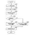
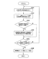
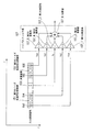
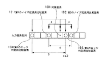
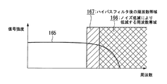
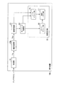
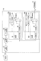
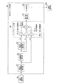
第1の実施形態における表示装置の機能ブロック図である。It is a functional block diagram of the display apparatus in a 1st embodiment. 第1の実施形態における液晶表示部の機能ブロック図である。It is a functional block diagram of the liquid crystal display part in 1st Embodiment. 第1の実施形態における雑音低減部の機能ブロック図である。It is a functional block diagram of the noise reduction part in 1st Embodiment. ノイズ量検出部により読み出されるフレームについて説明するための図である。It is a figure for demonstrating the flame | frame read by the noise amount detection part. ノイズ量検出部による最頻値の算出方法について説明するための図である。It is a figure for demonstrating the calculation method of the mode value by a noise amount detection part. 対象画素の輝度値が2つの比較画素の輝度値よりも小さいときの、フレーム間ノイズ量低減部のノイズ低減処理を説明するための図である。It is a figure for demonstrating the noise reduction process of the noise amount reduction part between frames when the luminance value of an object pixel is smaller than the luminance value of two comparison pixels. 対象画素の輝度値が2つの比較画素の輝度値よりも大きいときの、フレーム間ノイズ量低減部のノイズ低減処理を説明するための図である。It is a figure for demonstrating the noise reduction process of the noise amount reduction part between frames when the luminance value of an object pixel is larger than the luminance value of two comparison pixels. 第1の実施形態におけるエッジ判定部の機能ブロック図である。It is a functional block diagram of the edge determination part in 1st Embodiment. エッジ判定用比較画素とノイズ低減用比較画素の関係について説明するための図である。It is a figure for demonstrating the relationship between the comparison pixel for edge determination, and the comparison pixel for noise reduction. エッジ判定部におけるハイパスフィルタ部の処理について説明するための図である。It is a figure for demonstrating the process of the high pass filter part in an edge determination part. 第1の実施形態における水平方向ノイズ低減部の機能ブロック図である。It is a functional block diagram of the horizontal direction noise reduction part in 1st Embodiment. 第1の実施形態における表示装置の処理の流れを示したフローチャートである。It is the flowchart which showed the flow of the process of the display apparatus in 1st Embodiment. 図12のステップS102の雑音低減処理の流れを示したフローチャートである。It is the flowchart which showed the flow of the noise reduction process of step S102 of FIG. 図13のステップS201のノイズ量αの算出の流れを示したフローチャートである。It is the flowchart which showed the flow of calculation of noise amount (alpha) of step S201 of FIG. エッジ判定用比較画素として4つの比較画素を抽出した例を示した図である。It is the figure which showed the example which extracted four comparison pixels as a comparison pixel for edge determination. 2つのエッジ判定用比較画素の間隔が、2つのノイズ低減用比較画素の間隔以上である例を示した図である。It is the figure which showed the example whose space | interval of two comparison pixels for edge determination is more than the space | interval of two comparison pixels for noise reduction. 映像信号の信号強度と周波数の関係の一例が示された図である。It is the figure by which an example of the relationship between the signal strength of a video signal and a frequency was shown. 第2の実施形態における表示装置の機能ブロック図である。It is a functional block diagram of the display apparatus in 2nd Embodiment. 第2の実施形態における雑音低減部の機能ブロック図である。It is a functional block diagram of the noise reduction part in 2nd Embodiment. 第2の実施形態における第2のエッジ判定部の機能ブロック図である。It is a functional block diagram of the 2nd edge judgment part in a 2nd embodiment. 第2の実施形態におけるエッジ判定用比較画素とノイズ低減用比較画素の関係について説明するための図である。It is a figure for demonstrating the relationship between the comparison pixel for edge determination in the 2nd Embodiment, and the comparison pixel for noise reduction. 第2の実施形態における垂直方向ノイズ低減部の機能ブロック図である。It is a functional block diagram of the vertical direction noise reduction part in 2nd Embodiment. 図12のステップS102に示された第2の実施形態における雑音低減処理の流れを示したフローチャートである。It is the flowchart which showed the flow of the noise reduction process in 2nd Embodiment shown by FIG.12 S102.

<第1の実施形態>
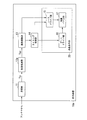
以下、本発明の第1の実施形態について、図面を参照して詳細に説明する。図1は、本発明の第1の実施形態における表示装置の機能ブロック図である。表示装置10aは、受信部11と、雑音低減部12aと、画像調整部13と、タイミング制御部14と、液晶表示部20とを備える。液晶表示部20は、ソースドライバ部15と、ゲートドライバ部16と、液晶パネル部17とを備える。
<First Embodiment>
Hereinafter, a first embodiment of the present invention will be described in detail with reference to the drawings. FIG. 1 is a functional block diagram of a display device according to the first embodiment of the present invention. The display device 10a includes a reception unit 11, a noise reduction unit 12a, an image adjustment unit 13, a timing control unit 14, and a liquid crystal display unit 20. The liquid crystal display unit 20 includes a source driver unit 15, a gate driver unit 16, and a liquid crystal panel unit 17.

受信部11は、一例として、不図示のアンテナから供給されたデジタルテレビジョン放送の複数チャネルの高周波信号を受信する。受信部11は、受信した信号から希望のチャネルの変調信号を抽出し、抽出した変調信号をベースバンドの信号に変換し、変換したベースバンドの信号を所定のサンプリング周波数でデジタル信号へ変換する。
なお、受信部11は、不図示のアンテナから供給されたアナログテレビジョン放送の複数チャネルの高周波信号を受信して、これをデジタル信号へ変換してもよい。
As an example, the receiving unit 11 receives high-frequency signals of a plurality of channels of digital television broadcasting supplied from an antenna (not shown). The receiving unit 11 extracts a modulation signal of a desired channel from the received signal, converts the extracted modulation signal into a baseband signal, and converts the converted baseband signal into a digital signal at a predetermined sampling frequency.
The receiving unit 11 may receive a plurality of high-frequency signals of an analog television broadcast supplied from an antenna (not shown) and convert them into digital signals.

受信部11は、変換されたデジタル信号からデジタルデータMPEG(Moving Picture Experts Group)−2トランスポートストリーム(以下、「MPEG−2TS」と言う)信号を抽出する。   The receiving unit 11 extracts a digital data MPEG (Moving Picture Experts Group) -2 transport stream (hereinafter referred to as “MPEG-2TS”) signal from the converted digital signal.

受信部11は、MPEG−2TS信号からTS(Transport Stream、トランスポートストリーム)パケットを抽出し、映像信号および音声復号のデータを復号する。受信部11は、復号した映像信号SINを雑音低減部12aへ供給する。
ここで、映像信号SINは、画像の主走査方向(横方向、水平方向)に隣接して並ぶ画素の輝度信号と、色差信号(Cb、Cr)とからなるインターレース信号である。
The receiving unit 11 extracts a TS (Transport Stream) packet from the MPEG-2 TS signal, and decodes the video signal and audio decoding data. The receiving unit 11 supplies the decoded video signal SIN to the noise reducing unit 12a.
Here, the video signal SIN is an interlace signal composed of a luminance signal of pixels arranged adjacent to each other in the main scanning direction (horizontal direction and horizontal direction) of the image and a color difference signal (Cb, Cr).

雑音低減部12aは、受信部11から供給された映像信号SINを受信する。雑音低減部12aは、後述する処理によって映像信号SINから雑音を低減した映像信号Soutを算出し、その映像信号Soutを画像調整部13へ供給する。 Noise reduction unit 12a receives the supplied video signal S IN from the receiving section 11. Noise reduction unit 12a calculates a video signal S out with reduced noise from the video signal S IN by the processing to be described later, and supplies the video signal S out to the image adjustment unit 13.

画像調整部13は、雑音低減部12aから供給された映像信号SOUTをプログレッシブ信号に変換する。また、画像調整部13は、変換後のプログレッシブ信号の画素数を、表示部の解像度に合わせて調整するスケーリング処理を行う。画像調整部13は、スケーリング処理後の映像信号をRGB信号(Red、Green、Blueのカラービデオ信号)に変換する。画像調整部13は、RGB信号をタイミング制御部14と液晶表示部20内のソースドライバ部15とへ供給する。 The image adjustment unit 13 converts the video signal S OUT supplied from the noise reduction unit 12a into a progressive signal. Further, the image adjustment unit 13 performs a scaling process for adjusting the number of pixels of the converted progressive signal in accordance with the resolution of the display unit. The image adjustment unit 13 converts the video signal after the scaling process into an RGB signal (Red, Green, Blue color video signal). The image adjustment unit 13 supplies RGB signals to the timing control unit 14 and the source driver unit 15 in the liquid crystal display unit 20.

なお、画像調整部13は、映像信号SOUTがプログレッシブ信号であれば、前述のインターレース信号からプログレッシブ信号への変換をしない。その場合、画像調整部13は、映像信号SOUTの画素数を表示部の解像度に合わせて調整するスケーリング処理を行う。 Note that if the video signal S OUT is a progressive signal, the image adjustment unit 13 does not convert the above-described interlace signal into a progressive signal. In that case, the image adjusting unit 13 performs scaling processing to tailor the number of pixels of the video signal S OUT to a display unit of the resolution.

タイミング制御部14は、液晶パネル部17に供給される映像データを平面上の画素に配分するためのクロック信号などを生成する。タイミング制御部14は、液晶表示部20内のソースドライバ部15と、ゲートドライバ部16へ、生成したクロック信号を供給する。   The timing control unit 14 generates a clock signal or the like for distributing the video data supplied to the liquid crystal panel unit 17 to the pixels on the plane. The timing control unit 14 supplies the generated clock signal to the source driver unit 15 and the gate driver unit 16 in the liquid crystal display unit 20.

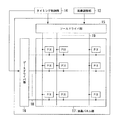
図2は、第1の実施形態における液晶表示部20の機能ブロック図である。液晶表示部20は、アクティブマトリクス型の表示装置である。液晶表示部20は、マトリクス状に配された画素PIXを有する液晶パネル部17と、ゲート線18と、ソース線19と、ゲート線18を駆動するゲートドライバ部16と、ソース線19を駆動するソースドライバ部15と、を備える。   FIG. 2 is a functional block diagram of the liquid crystal display unit 20 in the first embodiment. The liquid crystal display unit 20 is an active matrix display device. The liquid crystal display unit 20 drives the liquid crystal panel unit 17 having the pixels PIX arranged in a matrix, the gate line 18, the source line 19, the gate driver unit 16 that drives the gate line 18, and the source line 19. A source driver unit 15.

ソースドライバ15は、画像調整部13から供給されたRGB信号から液晶駆動用の階調化された電圧を生成する。ソースドライバ部15は、ソース線19ごとに、その階調化された電圧を、内部のホールド回路で保持する。
ソースドライバ部15は、タイミング制御部14から供給されたクロック信号を受信すると、画面の縦方向の配列に対して、クロック信号に同期して、階調化された電圧(ソース信号)を液晶パネル部17のTFT(Thin Film Transistor、薄膜トランジスタ)のソース線19および各TFTを介して画素PIXの不図示のサブ画素に供給する。
The source driver 15 generates a gradation voltage for driving liquid crystal from the RGB signals supplied from the image adjustment unit 13. The source driver unit 15 holds the gradation voltage for each source line 19 by an internal hold circuit.
When the source driver unit 15 receives the clock signal supplied from the timing control unit 14, the source driver unit 15 supplies the gradation voltage (source signal) to the liquid crystal panel in synchronization with the clock signal with respect to the vertical arrangement of the screen. This is supplied to a sub-pixel (not shown) of the pixel PIX via a source line 19 of each TFT (Thin Film Transistor) of the unit 17 and each TFT.

ゲートドライバ部16は、タイミング制御部14から供給されたクロック信号を受信する。ゲートドライバ部16は、表示部17のTFTのゲート線18を通じて画面のサブ画素の1行分に対して、クロック信号に同期して、所定の走査信号を各TFTのゲートに供給する。   The gate driver unit 16 receives the clock signal supplied from the timing control unit 14. The gate driver unit 16 supplies a predetermined scanning signal to the gate of each TFT in synchronization with the clock signal for one row of sub-pixels on the screen through the TFT gate line 18 of the display unit 17.

液晶パネル部17は、アレイ基板と対向基板と液晶とを備える。アレイ基板上のゲート線とデータ線との交点ごとに、TFTとTFTのドレイン電極に接続されている画素電極と対向電極(対向基板上のストリップ電極により構成されている)とが1組ずつ配置されて、画素、特にサブ画素を構成している。また、画素電極と対向電極との間には、封入された液晶が存在する。また、液晶パネル部17は、画素ごとに、3原色RGB(Red、Green、Blue)に対応する3つのサブ画素(不図示)を有する。液晶パネル部17は、そのサブ画素毎に1つずつのTFTを有する。これらのサブ画素はそれぞれのスイッチング素子であるTFT(薄膜トランジスタ)を介してゲート線18及びデータ配線19に接続される。   The liquid crystal panel unit 17 includes an array substrate, a counter substrate, and a liquid crystal. A pixel electrode connected to the TFT and the drain electrode of the TFT and a counter electrode (consisting of a strip electrode on the counter substrate) are arranged for each intersection of the gate line and the data line on the array substrate. Thus, a pixel, particularly a sub-pixel, is configured. Further, sealed liquid crystal exists between the pixel electrode and the counter electrode. In addition, the liquid crystal panel unit 17 has three sub-pixels (not shown) corresponding to the three primary colors RGB (Red, Green, Blue) for each pixel. The liquid crystal panel unit 17 has one TFT for each sub-pixel. These sub-pixels are connected to a gate line 18 and a data line 19 through TFTs (thin film transistors) which are respective switching elements.

TFTのゲート電極は、ゲートドライバ部16から供給されたゲート信号を受信して、ゲート信号が例えばハイレベルの時、そのTFTが選択されてオン状態となる。TFTのソース電極は、ソースドライバ15から供給されたソース信号を受信するから、これによって、TFTのドレイン電極に接続されている画素電極に階調化された電圧が印加される。   The gate electrode of the TFT receives the gate signal supplied from the gate driver unit 16, and when the gate signal is at a high level, for example, the TFT is selected and turned on. Since the source electrode of the TFT receives the source signal supplied from the source driver 15, the gradation voltage is applied to the pixel electrode connected to the drain electrode of the TFT.

その階調化された電圧に応じて、液晶の配向が変化し、これによって液晶の光の透過度が変化する。その階調化された電圧がTFTのドレイン電極に接続されている画素電極と対向電極との間の液晶部分により構成される液晶容量に保持されて、液晶の配向が維持される。また、次の信号がソース電極に到来するまで液晶の配向が維持され、その結果、液晶の光の透過度も維持される。   The alignment of the liquid crystal changes in accordance with the gradation voltage, thereby changing the light transmittance of the liquid crystal. The gradation voltage is held in the liquid crystal capacitor formed by the liquid crystal portion between the pixel electrode connected to the drain electrode of the TFT and the counter electrode, and the alignment of the liquid crystal is maintained. Further, the orientation of the liquid crystal is maintained until the next signal arrives at the source electrode, and as a result, the light transmittance of the liquid crystal is also maintained.

以上説明したようにして、液晶パネル部17は、供給された映像データを階調表示する。なお、本実施形態では透過型の液晶パネルについて説明したが、これに限らず反射型の液晶パネルでもよい。   As described above, the liquid crystal panel unit 17 performs gradation display on the supplied video data. Although the transmissive liquid crystal panel has been described in the present embodiment, the present invention is not limited to this, and a reflective liquid crystal panel may be used.

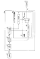
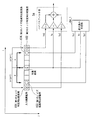
図3は、第1の実施形態における雑音低減部12aの機能ブロック図である。雑音低減部12aは、一時記憶部31と、ノイズ量検出部32と、フレーム間ノイズ低減部33と、フレーム内ノイズ低減部40aとを備える。
一時記憶部31は、受信部11から供給された映像信号SINを所定のフレーム数だけ記憶する。
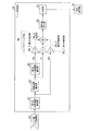
FIG. 3 is a functional block diagram of the noise reduction unit 12a in the first embodiment. The noise reduction unit 12a includes a temporary storage unit 31, a noise amount detection unit 32, an inter-frame noise reduction unit 33, and an intra-frame noise reduction unit 40a.
Temporary storage unit 31 stores the video signal S IN supplied from the receiving unit 11 a predetermined number of frames only.

ノイズ量検出部32は、一時記憶部31から雑音低減の対象となる対象画素を含むフレームの映像信号と、当該フレームの1つ前のフレームの映像信号と、当該フレームの1つ後のフレームの映像信号と、を読み出す。   The noise amount detection unit 32 receives the video signal of the frame including the target pixel from which noise is to be reduced from the temporary storage unit 31, the video signal of the frame immediately before the frame, and the frame after the frame. Video signal is read out.

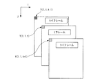
図4は、ノイズ量検出部32により読み出されるフレームについて説明するための図である。同図において、雑音低減の対象となる対象画素を含むt番目のフレームの画像と、当該フレームの1つ前のt−1番目のフレームの画像と、当該フレームの1つ後のt+1番目のフレームの画像とが示されている(tは2以上の整数)。   FIG. 4 is a diagram for explaining a frame read by the noise amount detection unit 32. In the figure, an image of a t-th frame including a target pixel to be subjected to noise reduction, an image of a t−1th frame immediately before the frame, and a t + 1th frame immediately after the frame. (T is an integer of 2 or more).

更に、同図において、ij座標系において、t番目のフレームの左端(i=1,j=1)の画素の輝度値Y(1,1,t)と、当該左端の画素の位置に相当する1つ前のフレームの画素の輝度値Y(1,1,t−1)と、当該左端の画素の位置に相当する1つ後のフレームの画素の輝度値Y(1,1,t+1)とが示されている。   Further, in the figure, in the ij coordinate system, this corresponds to the luminance value Y (1, 1, t) of the pixel at the left end (i = 1, j = 1) of the t-th frame and the position of the pixel at the left end. The luminance value Y (1,1, t-1) of the pixel of the previous frame, and the luminance value Y (1,1, t + 1) of the pixel of the next frame corresponding to the position of the leftmost pixel It is shown.

図3に戻って、ノイズ量検出部32は、対象画素を含むフレームの画素の輝度値Y(i、j、t)と、当該対象画素の位置に相当する1つ前のフレームの画素Y(i、j、t−1)と、当該対象画素の位置に相当する1つ後のフレームの画素Y(i、j、t+1)とを用いて、フレーム間の輝度値差の平均ΔYを以下の式(1)に従って、算出する。   Returning to FIG. 3, the noise amount detection unit 32 determines the luminance value Y (i, j, t) of the pixel of the frame including the target pixel, and the pixel Y (1) of the previous frame corresponding to the position of the target pixel. i, j, t−1) and the pixel Y (i, j, t + 1) of the next frame corresponding to the position of the target pixel, the average ΔY of the luminance value difference between frames is It calculates according to Formula (1).

ΔY=(|Y(i、j、t−1)−Y(i、j、t)|+|Y(i、j、t+1)−Y(i、j、t)|)/2 (1)   ΔY = (| Y (i, j, t−1) −Y (i, j, t) | + | Y (i, j, t + 1) −Y (i, j, t) |) / 2 (1)

なお、本実施形態におけるノイズ量検出部32は、1フレーム前と1フレーム後の画像データを用いてフレーム間の輝度値差の平均を算出したがこれに限らず、2フレーム以上前後するフレームの画像データを用いてフレーム間の輝度値差の平均を算出してもよい。その算出方法は以上の説明から自明であろう。   Note that the noise amount detection unit 32 in the present embodiment calculates the average of luminance value differences between frames using the image data before and after one frame, but is not limited to this. You may calculate the average of the luminance value difference between frames using image data. The calculation method will be obvious from the above description.

ノイズ量検出部32は、対象画素を含むフレーム内の全ての画素で、フレーム間の輝度値差の平均ΔYを算出する。そして、ノイズ量検出部32は、フレーム間の輝度値差の平均ΔYの最頻値をノイズ量αとして算出し、算出したノイズ量αを示す信号をフレーム内ノイズ低減部40aの後述する水平方向ノイズ低減部60に出力する。また、ノイズ量検出部32は、算出したノイズ量αを示す信号を一時記憶部31から読み出した連続する3フレーム分の映像信号と伴にフレーム間ノイズ低減部33に出力する。   The noise amount detection unit 32 calculates an average ΔY of luminance value differences between frames at all pixels in the frame including the target pixel. Then, the noise amount detection unit 32 calculates the mode value of the average ΔY of luminance value differences between frames as the noise amount α, and a signal indicating the calculated noise amount α in the horizontal direction described later of the intra-frame noise reduction unit 40a. Output to the noise reduction unit 60. Further, the noise amount detection unit 32 outputs a signal indicating the calculated noise amount α to the inter-frame noise reduction unit 33 together with the video signals for three consecutive frames read from the temporary storage unit 31.

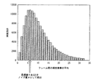
ここで、図5を用いて、最頻値の算出方法について説明する。図5は、ノイズ量検出部32による最頻値の算出方法について説明するための図である。同図において、フレーム間の輝度値差の平均ΔYの頻度分布が示されている。出現頻度が最大となるフレーム間の輝度値差の平均ΔYが最頻値であり、同図において最頻値は6である。この例では、ノイズ量検出部32は、最頻値である6をノイズ量αとして算出する。   Here, a method of calculating the mode value will be described with reference to FIG. FIG. 5 is a diagram for describing a mode value calculation method by the noise amount detection unit 32. In the figure, the frequency distribution of the average ΔY of the luminance value differences between frames is shown. The average ΔY of the luminance value differences between frames with the maximum appearance frequency is the mode value, and the mode value is 6 in FIG. In this example, the noise amount detection unit 32 calculates the mode value 6 as the noise amount α.

図3に戻って、フレーム間ノイズ量低減部33は、対象画素の画素値(例えば、輝度値、色差)と、該対象画素を含むフレームから所定のフレーム間隔だけ離れたフレームにおいて該対象画素の位置に相当する位置の画素の画素値(例えば、輝度値、色差)とに基づいて、フレーム間のノイズを低減する。一例として、フレーム間ノイズ量低減部33は、ノイズ量検出部32から入力されたノイズ量αを示す信号と、3フレーム分の輝度信号とに基づいて、フレーム間のノイズを低減する。具体的な処理について、図6および図7を用いて説明する。   Returning to FIG. 3, the inter-frame noise amount reduction unit 33 determines the pixel value (for example, luminance value, color difference) of the target pixel and the target pixel in a frame that is separated from the frame including the target pixel by a predetermined frame interval. Based on the pixel value (for example, luminance value, color difference) of the pixel at the position corresponding to the position, noise between frames is reduced. As an example, the inter-frame noise amount reduction unit 33 reduces the noise between frames based on the signal indicating the noise amount α input from the noise amount detection unit 32 and the luminance signal for three frames. Specific processing will be described with reference to FIGS. 6 and 7.

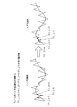
図6は、対象画素の輝度値が2つの比較画素の輝度値よりも小さいときの、フレーム間ノイズ量低減部33のノイズ低減処理を説明するための図である。同図において、向かって左側にノイズ低減前の輝度信号の電圧値(輝度値を示す電圧値)と、向かって右側にノイズ低減後の輝度信号の電圧値(輝度値を示す電圧値)とが示されている。   FIG. 6 is a diagram for explaining the noise reduction processing of the interframe noise amount reduction unit 33 when the luminance value of the target pixel is smaller than the luminance values of the two comparison pixels. In the figure, the voltage value of the luminance signal before the noise reduction (voltage value indicating the luminance value) on the left side and the voltage value of the luminance signal after the noise reduction (voltage value indicating the luminance value) on the right side. It is shown.

同図において、向かって左側にあるノイズ低減前のt番目のフレームの対象画素の輝度値Y(i,j,t)が、当該対象画素の位置に相当する1つ前のフレームの画素の輝度値Y(i,j,t−1)および当該対象画素の位置に相当する1つ後のフレームの画素の輝度値Y(i,j,t+1)よりも小さいことが示されている。また、向かって右側にあるノイズ低減後のt番目のフレームの対象画素の輝度値Y´(i,j,t)は、ノイズ低減前の輝度値Y(i,j,t)にノイズ量αが加算されたものである。   In the figure, the luminance value Y (i, j, t) of the target pixel of the t-th frame before noise reduction on the left side in the figure is the luminance of the pixel of the previous frame corresponding to the position of the target pixel. The value Y (i, j, t-1) and the luminance value Y (i, j, t + 1) of the pixel of the next frame corresponding to the position of the target pixel are shown. Further, the luminance value Y ′ (i, j, t) of the target pixel of the t-th frame after noise reduction on the right side is the noise amount α to the luminance value Y (i, j, t) before noise reduction. Is added.

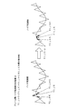
図7は、対象画素の輝度値が2つの比較画素の輝度値よりも大きいときの、フレーム間ノイズ量低減部33のノイズ低減処理を説明するための図である。同図において、向かって左側にノイズ低減前の輝度信号の電圧値(輝度値を示す電圧値)と、向かって右側にノイズ低減後の輝度信号の電圧値(輝度値を示す電圧値)とが示されている。   FIG. 7 is a diagram for explaining the noise reduction processing of the inter-frame noise amount reduction unit 33 when the luminance value of the target pixel is larger than the luminance values of the two comparison pixels. In the figure, the voltage value of the luminance signal before the noise reduction (voltage value indicating the luminance value) on the left side and the voltage value of the luminance signal after the noise reduction (voltage value indicating the luminance value) on the right side. It is shown.

同図において、向かって左側にあるノイズ低減前のt番目のフレームの対象画素の輝度値Y(i,j,t)が、当該対象画素の位置に相当する1つ前のフレームの画素の輝度値Y(i,j,t−1)および当該対象画素の位置に相当する1つ後のフレームの画素の輝度値Y(i,j,t+1)よりも大きいことが示されている。
向かって右側にあるノイズ低減後のt番目のフレームの対象画素の輝度値Y´(i,j,t)は、ノイズ低減前の輝度値Y(i,j,t)からノイズ量αが減算されたものである。
In the figure, the luminance value Y (i, j, t) of the target pixel of the t-th frame before noise reduction on the left side in the figure is the luminance of the pixel of the previous frame corresponding to the position of the target pixel. The value Y (i, j, t−1) and the luminance value Y (i, j, t + 1) of the pixel of the next frame corresponding to the position of the target pixel are shown.
The luminance value Y ′ (i, j, t) of the target pixel of the t-th frame after noise reduction on the right side is subtracted by the noise amount α from the luminance value Y (i, j, t) before noise reduction. It has been done.

フレーム間ノイズ低減部33は、t番目のフレームの対象画素の輝度値Y(i,j,t)と当該対象画素の位置に相当する1つ前のフレームの画素の輝度値Y(i,j,t−1)と当該対象画素の位置に相当する1つ後のフレームの画素の輝度値Y(i,j,t+1)とを比較し、対象画素の輝度値Y(i,j,t)が最小の場合、対象画素の輝度値Y(i,j,t)にノイズ量αを加算する。一方、対象画素の輝度値Y(i,j,t)が最大の場合、対象画素の輝度値Y(i,j,t)からノイズ量αを減算する。   The inter-frame noise reduction unit 33 calculates the luminance value Y (i, j, t) of the target pixel in the t-th frame and the luminance value Y (i, j) of the pixel in the previous frame corresponding to the position of the target pixel. , T−1) and the luminance value Y (i, j, t + 1) of the pixel of the next frame corresponding to the position of the target pixel, and the luminance value Y (i, j, t) of the target pixel Is the minimum, the noise amount α is added to the luminance value Y (i, j, t) of the target pixel. On the other hand, when the luminance value Y (i, j, t) of the target pixel is maximum, the noise amount α is subtracted from the luminance value Y (i, j, t) of the target pixel.

図3に戻って、フレーム間ノイズ低減部33は、上記処理をt番目のフレームの全ての画素で行うことにより、フレーム間ノイズ低減後のt番目のフレームの輝度信号を生成し、生成したフレーム間ノイズ低減後の輝度信号をフレーム内ノイズ低減部40aの後述するエッジ判定部50と、ノイズ低減部42とに出力する。   Returning to FIG. 3, the inter-frame noise reduction unit 33 generates the luminance signal of the t-th frame after reducing the inter-frame noise by performing the above process on all the pixels of the t-th frame, and generates the generated frame. The luminance signal after the inter-noise reduction is output to an edge determination unit 50 (to be described later) of the intra-frame noise reduction unit 40a and the noise reduction unit 42.

フレーム内ノイズ低減部40aは、フレーム間ノイズ低減部33から入力された画像データに基づいて、フレーム内のノイズを低減し、フレーム内のノイズを低減した映像信号SOUTを画像調整部13に出力する。ここで、フレーム内ノイズ低減部40aは、エッジ判定部50とノイズ低減部42とを備える。また、ノイズ低減部42は、水平方向ノイズ低減部60と、信号選択部70とを備える。 The intra-frame noise reduction unit 40 a reduces the intra-frame noise based on the image data input from the inter-frame noise reduction unit 33, and outputs the video signal S OUT with the reduced intra-frame noise to the image adjustment unit 13. To do. Here, the intra-frame noise reduction unit 40 a includes an edge determination unit 50 and a noise reduction unit 42. The noise reduction unit 42 includes a horizontal noise reduction unit 60 and a signal selection unit 70.

続いて、フレーム内ノイズ低減部40aが備える各部の処理について説明する。まず、図8を用いて、エッジ判定部50の処理について説明する。図8は、第1の実施形態におけるエッジ判定部50の機能ブロック図である。エッジ判定部50は、第1の比較画素抽出部51と、対象画素抽出部52と、第2の比較画素抽出部53と、ハイパスフィルタ部54と、絶対値算出部55と、判定部56とを備える。また、ハイパスフィルタ部54は、第1の乗算部54_1と、第2の乗算部54_2と、第3の乗算部54_3と、加算部54_4とを備える。   Next, processing of each unit included in the intra-frame noise reduction unit 40a will be described. First, the process of the edge determination part 50 is demonstrated using FIG. FIG. 8 is a functional block diagram of the edge determination unit 50 in the first embodiment. The edge determination unit 50 includes a first comparison pixel extraction unit 51, a target pixel extraction unit 52, a second comparison pixel extraction unit 53, a high-pass filter unit 54, an absolute value calculation unit 55, and a determination unit 56. Is provided. The high-pass filter unit 54 includes a first multiplier 54_1, a second multiplier 54_2, a third multiplier 54_3, and an adder 54_4.

本実施形態では、ラスタスキャンで画像の左上から右下に掛けて順に画像が表示されることを前提とする。第1の比較画素抽出部51は、フレーム間ノイズ低減部33から入力されたフレーム間ノイズ低減後の輝度信号を用いて、対象画素と同一フレーム内において、対象画素よりも向かってc画素だけ左側にある画素の輝度信号をエッジ判定用比較画素の輝度値Yp2を示す輝度信号として抽出する(cは正の整数)。ここで、対象画素とエッジ判定用比較画素との画素間隔cは、対象画素とノイズ低減部42により用いられるノイズ低減用比較画素との画素間隔aよりも1だけ大きい値である(aは正の整数)。   In the present embodiment, it is assumed that images are displayed in order from the upper left to the lower right of the image by raster scanning. The first comparison pixel extraction unit 51 uses the luminance signal after the inter-frame noise reduction input from the inter-frame noise reduction unit 33, and is left by c pixels toward the target pixel in the same frame as the target pixel. Is extracted as a luminance signal indicating the luminance value Yp2 of the edge determination comparison pixel (c is a positive integer). Here, the pixel interval c between the target pixel and the edge determination comparison pixel is a value larger by one than the pixel interval a between the target pixel and the noise reduction comparison pixel used by the noise reduction unit 42 (a is a positive value). Integer).

具体的には、例えば、第1の比較画素抽出部51は、入力信号を遅延させる遅延回路を備える。第1の比較画素抽出部51の遅延回路は、フレーム間ノイズ低減部33から入力されたフレーム間ノイズ低減後の輝度信号を、フレームの左端(i=1,j=1)の画素から対象画素から水平方向に向かってc画素だけ左側の画素までの画素間隔に相当する遅延時間だけ遅らせる。   Specifically, for example, the first comparison pixel extraction unit 51 includes a delay circuit that delays the input signal. The delay circuit of the first comparison pixel extraction unit 51 converts the luminance signal after the inter-frame noise reduction input from the inter-frame noise reduction unit 33 from the pixel at the left end (i = 1, j = 1) of the frame to the target pixel. Is delayed by a delay time corresponding to the pixel interval from the pixel c to the pixel on the left side in the horizontal direction.

第1の比較画素抽出部51は、抽出したエッジ判定用比較画素の輝度値Yp2を示す輝度信号をハイパスフィルタ部54の第1の乗算部54_1に出力する。また、第1の比較画素抽出部51は、遅延回路によりフレーム間ノイズ低減後の輝度信号を遅らせることにより生成された輝度信号を第1の遅延輝度信号として対象画素抽出部52に出力する。   The first comparison pixel extraction unit 51 outputs a luminance signal indicating the luminance value Yp2 of the extracted edge determination comparison pixel to the first multiplication unit 54_1 of the high-pass filter unit 54. Further, the first comparison pixel extraction unit 51 outputs the luminance signal generated by delaying the luminance signal after the inter-frame noise reduction by the delay circuit to the target pixel extraction unit 52 as the first delayed luminance signal.

対象画素抽出部52は、第1の比較画素抽出部51から入力された第1の遅延輝度信号から対象画素の輝度値Ycを示す輝度信号を抽出し、その対象画素の輝度値Ycを示す輝度信号をハイパスフィルタ部54の第2の乗算部54_2に出力する。   The target pixel extraction unit 52 extracts a luminance signal indicating the luminance value Yc of the target pixel from the first delayed luminance signal input from the first comparison pixel extraction unit 51, and the luminance indicating the luminance value Yc of the target pixel The signal is output to the second multiplication unit 54_2 of the high-pass filter unit 54.

具体的には、例えば、対象画素抽出部52は、入力信号を遅延させる遅延回路を備える。対象画素抽出部52の遅延回路は、第1の比較画素抽出部51から入力された第1の遅延輝度信号をc画素間隔に相当する時間だけ遅らせることにより、対象画素の輝度値Ycを示す輝度信号を抽出する。
また、対象画素抽出部52は、遅延回路により第1の遅延輝度信号を遅らせることにりより生成された第2の遅延輝度信号を、第2の比較画素抽出部53に出力する。
Specifically, for example, the target pixel extraction unit 52 includes a delay circuit that delays an input signal. The delay circuit of the target pixel extraction unit 52 delays the first delayed luminance signal input from the first comparison pixel extraction unit 51 by a time corresponding to the c pixel interval, thereby indicating the luminance value Yc of the target pixel. Extract the signal.
Further, the target pixel extraction unit 52 outputs the second delayed luminance signal generated by delaying the first delayed luminance signal by the delay circuit to the second comparison pixel extraction unit 53.

第2の比較画素抽出部53は、対象画素抽出部52から入力された第2の遅延輝度信号を用いて、対象画素と同一フレーム内において、対象画素よりも向かってc画素分右側にある画素の輝度信号をエッジ判定用比較画素の輝度値Yn2を示す輝度信号として抽出する。そして、第2の比較画素抽出部53は、抽出したエッジ判定用比較画素の輝度値Yn2を示す輝度信号を第3の乗算部54_3に出力する。   The second comparison pixel extraction unit 53 uses the second delayed luminance signal input from the target pixel extraction unit 52, and is a pixel on the right side by c pixels from the target pixel in the same frame as the target pixel. Is extracted as a luminance signal indicating the luminance value Yn2 of the edge determination comparison pixel. Then, the second comparison pixel extraction unit 53 outputs a luminance signal indicating the luminance value Yn2 of the extracted edge determination comparison pixel to the third multiplication unit 54_3.

具体的には、例えば、第2の比較画素抽出部53は、入力信号を遅延させる遅延回路を備える。第2の比較画素抽出部53の遅延回路は、対象画素抽出部52から入力された第2の遅延輝度信号をc画素間隔に相当する時間だけ遅らせることにより、エッジ判定用比較画素の輝度値Yn2を示す輝度信号を抽出する。   Specifically, for example, the second comparison pixel extraction unit 53 includes a delay circuit that delays the input signal. The delay circuit of the second comparison pixel extraction unit 53 delays the second delayed luminance signal input from the target pixel extraction unit 52 by a time corresponding to the c pixel interval, whereby the luminance value Yn2 of the edge determination comparison pixel. Is extracted.

これにより、エッジ判定部50は、対象画素を中心として点対称の位置にある2つのエッジ判定用比較画素を抽出することができる。換言すれば、エッジ判定部50により用いられる2つのエッジ判定用比較画素は、対象画素を中心として点対称の位置にある。
なお、画素間隔cを画素間隔aよりも1だけ大きい値としたがこれに限らず、画素間隔cは画素間隔aよりも大きい値であればよい。すなわち、エッジ判定部50により用いられる各エッジ判定用比較画素は、対象画素を基準としてノイズ低減部42により用いられる各ノイズ低減用比較画素が位置する画素よりも外に位置すればよい。
Thereby, the edge determination part 50 can extract the two comparison pixels for edge determination in the point-symmetrical position centering on the target pixel. In other words, the two edge determination comparison pixels used by the edge determination unit 50 are in a point-symmetric position with respect to the target pixel.
In addition, although the pixel interval c is set to a value larger by 1 than the pixel interval a, the present invention is not limited thereto, and the pixel interval c may be a value larger than the pixel interval a. That is, each edge determination comparison pixel used by the edge determination unit 50 only needs to be located outside the pixel where each noise reduction comparison pixel used by the noise reduction unit 42 is located with reference to the target pixel.

図9は、エッジ判定用比較画素とノイズ低減用比較画素の関係について説明するための図である。同図において、ij座標系において、対象画素を含むフレーム内におけるある入力画素配列において、対象画素の位置と、エッジ判定用比較画素の位置と、ノイズ低減用比較画素の位置が示されている。   FIG. 9 is a diagram for explaining the relationship between the edge determination comparison pixels and the noise reduction comparison pixels. In the figure, in the ij coordinate system, the position of the target pixel, the position of the edge determination comparison pixel, and the position of the noise reduction comparison pixel are shown in a certain input pixel array in the frame including the target pixel.

同図において、第1のエッジ判定用比較画素101は、対象画素を基準として第1のノイズ低減用比較画素103の位置よりも1画素分、外に位置している。同様に、第2のエッジ判定用比較画素102は、対象画素を基準として第2のノイズ低減用比較画素104の位置よりも1画素分、外に位置している。上述したように、対象画素とエッジ判定用比較画素との画素間隔cは、対象画素とノイズ低減用比較画素との画素間隔aに1を加算した値である。   In the drawing, the first edge determination comparison pixel 101 is located one pixel outside the position of the first noise reduction comparison pixel 103 with respect to the target pixel. Similarly, the second edge determination comparison pixel 102 is positioned one pixel outside the position of the second noise reduction comparison pixel 104 with respect to the target pixel. As described above, the pixel interval c between the target pixel and the edge determination comparison pixel is a value obtained by adding 1 to the pixel interval a between the target pixel and the noise reduction comparison pixel.

対象画素の輝度値Ycは、エッジ判定部50のハイパスフィルタ部54と、水平方向ノイズ低減部60の後述する最大最小判定部64_1とに入力される。
第1のエッジ判定用比較画素101の輝度値Yp2は、エッジ判定部50のハイパスフィルタ部54に入力されること、および第2のエッジ判定用比較画素102の輝度値Yn2は、エッジ判定部50のハイパスフィルタ部54に入力される。
The luminance value Yc of the target pixel is input to the high-pass filter unit 54 of the edge determination unit 50 and the maximum / minimum determination unit 64_1 described later of the horizontal noise reduction unit 60.
The luminance value Yp2 of the first edge determination comparison pixel 101 is input to the high-pass filter unit 54 of the edge determination unit 50, and the luminance value Yn2 of the second edge determination comparison pixel 102 is the edge determination unit 50. Are input to the high-pass filter unit 54.

一方、第1のノイズ低減用比較画素103の輝度値Yp1は、水平方向ノイズ低減部60の後述する最大最小判定部64_1に入力されること、および第2のノイズ低減用比較画素104の輝度値Yn1は、水平方向ノイズ低減部60の後述する最大最小判定部64_1に入力される。   On the other hand, the luminance value Yp1 of the first noise reduction comparison pixel 103 is input to a maximum / minimum determination unit 64_1 described later of the horizontal noise reduction unit 60, and the luminance value of the second noise reduction comparison pixel 104. Yn1 is input to a maximum / minimum determination unit 64_1 described later of the horizontal noise reduction unit 60.

図8に戻って、第1の乗算部54_1は、第1の比較画素抽出部51から入力されたエッジ判定用比較画素の輝度値Yp2を−1/2倍し、算出値−1/2×Yp2を示す信号を加算部54_4に出力する。   Returning to FIG. 8, the first multiplication unit 54_1 multiplies the luminance value Yp2 of the edge determination comparison pixel input from the first comparison pixel extraction unit 51 by -1/2 to obtain a calculated value -1 / 2 ×. A signal indicating Yp2 is output to the adder 54_4.

第2の乗算部54_2は、第2の対象画素抽出部52から入力された対象画素の輝度値Ycを1倍し、算出値Ycを示す信号を加算部54_4に出力する。
第3の乗算部54_3は、第3の比較画素抽出部53から入力されたエッジ判定用比較画素の輝度値Yn2を−1/2倍し、算出値−1/2×Yn2を示す信号を加算部54_4に出力する。
The second multiplying unit 54_2 multiplies the luminance value Yc of the target pixel input from the second target pixel extracting unit 52, and outputs a signal indicating the calculated value Yc to the adding unit 54_4.
The third multiplication unit 54_3 multiplies the luminance value Yn2 of the comparison pixel for edge determination input from the third comparison pixel extraction unit 53 by -1/2, and adds a signal indicating the calculated value -1 / 2 × Yn2. To the unit 54_4.

加算部54_4は、第1の乗算部54_1から入力された算出値−1/2×Yp2を示す信号と、第2の乗算部54_2から入力された算出値Ycを示す信号と、算出値−1/2×Yn2を示す信号との和を算出し、算出した和(−1/2×Yp2+Yc−1/2×Yn2)を示す信号を絶対値算出部55に出力する。   The adder 54_4 includes a signal indicating the calculated value −1 / 2 × Yp2 input from the first multiplier 54_1, a signal indicating the calculated value Yc input from the second multiplier 54_2, and a calculated value−1. The signal indicating / 2 × Yn2 is calculated and a signal indicating the calculated sum (−1 / 2 × Yp2 + Yc−1 / 2 × Yn2) is output to the absolute value calculation unit 55.

絶対値算出部55は、加算部54_4から入力された和(−1/2×Yp2+Yc−1/2×Yn2)の絶対値を算出し、算出した絶対値|−1/2×Yp2+Yc−1/2×Yn2|を示す信号を判定部56に出力する。   The absolute value calculation unit 55 calculates the absolute value of the sum (−1 / 2 × Yp2 + Yc−1 / 2 × Yn2) input from the addition unit 54_4, and calculates the absolute value | −1 / 2 × Yp2 + Yc−1 / A signal indicating 2 × Yn2 | is output to the determination unit 56.

判定部56は、絶対値算出部55から入力された絶対値|−1/2×Yp2+Yc−1/2×Yn2|が所定の閾値(例えば、50)より大きいか否か判定する。判定部56は、当該絶対値が所定の閾値よりも大きい場合、対象画素はエッジであると判定し、判定結果を示す信号(例えば、1を示す信号)を信号選択部70に出力する。
一方、判定部56は、当該絶対値が所定の閾値以下の場合、対象画素はエッジでないと判定し、判定結果を示す信号(例えば、0を示す信号)を信号選択部70に出力する。
The determination unit 56 determines whether or not the absolute value | −1 / 2 × Yp2 + Yc−1 / 2 × Yn2 | input from the absolute value calculation unit 55 is greater than a predetermined threshold (for example, 50). When the absolute value is larger than the predetermined threshold, the determination unit 56 determines that the target pixel is an edge, and outputs a signal indicating the determination result (for example, a signal indicating 1) to the signal selection unit 70.
On the other hand, when the absolute value is equal to or smaller than the predetermined threshold, the determination unit 56 determines that the target pixel is not an edge, and outputs a signal indicating the determination result (for example, a signal indicating 0) to the signal selection unit 70.

なお、本実施形態では、ハイパスフィルタ部54はノイズ低減用比較画素の輝度値に乗じる係数を−1/2とし、対象画素の輝度値に乗じる係数を1としたが、これに限ったものではなく、これら3つの係数の総和が0になるような係数の組み合わせであれば良い。   In the present embodiment, the high-pass filter unit 54 sets the coefficient by which the luminance value of the noise reduction comparison pixel is multiplied by −½ and the coefficient by which the luminance value of the target pixel is multiplied by 1, but is not limited to this. However, any combination of coefficients may be used as long as the sum of these three coefficients becomes zero.

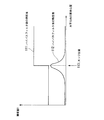
図10は、エッジ判定部50におけるハイパスフィルタ部54の処理について説明するための図である。縦軸は輝度値Y、横軸は水平方向の画素位置である。同図において、ハイパスフィルタ前の輝度値111と、ハイパスフィルタ後の輝度値112との一例が示されている。エッジ位置113でハイパスフィルタ後の輝度値112が最大になることが示されている。   FIG. 10 is a diagram for explaining the processing of the high-pass filter unit 54 in the edge determination unit 50. The vertical axis represents the luminance value Y, and the horizontal axis represents the pixel position in the horizontal direction. In the figure, an example of the luminance value 111 before the high-pass filter and the luminance value 112 after the high-pass filter is shown. It is shown that the luminance value 112 after the high-pass filter becomes maximum at the edge position 113.

ハイパスフィルタ部54が、対象画素を中心として点対称に位置するエッジ判定用比較画素を用いてハイパスフィルタを掛けることにより、エッジ位置113でハイパスフィルタ後の輝度値112が極大値を取るようにすることができる。これにより、エッジ判定部50は、ハイパスフィルタ後の輝度値に基づいて、対象画素がエッジであるか否か判定することができる。   The high-pass filter unit 54 applies the high-pass filter using the edge determination comparison pixel located symmetrically with respect to the target pixel, so that the luminance value 112 after the high-pass filter takes a maximum value at the edge position 113. be able to. Thereby, the edge determination part 50 can determine whether a target pixel is an edge based on the luminance value after a high-pass filter.

なお、本実施形態では、エッジ判定部50は、対象画素を中心として点対称に位置するエッジ判定用比較画素を用いたが、これに限ったものではない。エッジ判定部50により抽出される2つのエッジ判定用比較画素は、対象画素を中心として点対称でなくても、対象画素が2つのエッジ判定用比較画素の間にあればよい。   In the present embodiment, the edge determination unit 50 uses the edge determination comparison pixel positioned point-symmetrically with the target pixel as the center. However, the present invention is not limited to this. The two edge determination comparison pixels extracted by the edge determination unit 50 need not be point-symmetric with respect to the target pixel as long as the target pixel is between the two edge determination comparison pixels.

続いて、図11を用いてノイズ低減部42内の水平方向ノイズ低減部60について説明する。図11は、第1の実施形態における水平方向ノイズ低減部60の機能ブロック図である。水平方向ノイズ低減部60は、第3の比較画素抽出部61と、対象画素抽出部62と、第4の比較画素抽出部63と、ノイズ低減部64とを備える。また、ノイズ低減部64は、最大最小判定部64_1と、加算部64_2と、減算部64_3と、信号切替部64_4とを備える。   Next, the horizontal noise reduction unit 60 in the noise reduction unit 42 will be described with reference to FIG. FIG. 11 is a functional block diagram of the horizontal noise reduction unit 60 in the first embodiment. The horizontal noise reduction unit 60 includes a third comparison pixel extraction unit 61, a target pixel extraction unit 62, a fourth comparison pixel extraction unit 63, and a noise reduction unit 64. The noise reduction unit 64 includes a maximum / minimum determination unit 64_1, an addition unit 64_2, a subtraction unit 64_3, and a signal switching unit 64_4.

第3の比較画素抽出部61は、フレーム間ノイズ低減部33から入力されたフレーム間ノイズ低減後の輝度信号を用いて、対象画素と同一フレーム内において、対象画素よりも向かってa(=c−1)画素分左側にある画素の輝度信号をノイズ低減用比較画素の輝度値Yp1を示す輝度信号として抽出する。   The third comparison pixel extraction unit 61 uses the luminance signal after the inter-frame noise reduction input from the inter-frame noise reduction unit 33, and a (= c) toward the target pixel in the same frame as the target pixel. -1) The luminance signal of the pixel on the left side of the pixel is extracted as a luminance signal indicating the luminance value Yp1 of the noise reduction comparison pixel.

具体的には、例えば、第3の比較画素抽出部61は、入力信号を遅延させる遅延回路を備える。第3の比較画素抽出部61の遅延回路は、フレーム間ノイズ低減部33から入力されたフレーム間ノイズ低減後の輝度信号を、フレームの左端(i=1,j=1)の画素から対象画素から水平方向に向かってa画素だけ左側の画素までの画素間隔に相当する遅延時間だけ遅らせる。   Specifically, for example, the third comparison pixel extraction unit 61 includes a delay circuit that delays the input signal. The delay circuit of the third comparison pixel extraction unit 61 converts the luminance signal after inter-frame noise reduction input from the inter-frame noise reduction unit 33 from the pixel at the left end (i = 1, j = 1) of the frame to the target pixel. Is delayed by a delay time corresponding to the pixel interval from the pixel a to the pixel on the left side in the horizontal direction.

そして、第3の比較画素抽出部61は、抽出したノイズ低減用比較画素の輝度値Yp1を示す輝度信号を最大最小判定部64_1に出力する。
また、第3の比較画素抽出部61は、遅延回路により遅延させたフレーム間ノイズ低減後の輝度信号を遅らせることにより生成された輝度信号を第3の遅延輝度信号として対象画素抽出部62に出力する。
Then, the third comparison pixel extraction unit 61 outputs a luminance signal indicating the luminance value Yp1 of the extracted noise reduction comparison pixel to the maximum / minimum determination unit 64_1.
Further, the third comparison pixel extraction unit 61 outputs the luminance signal generated by delaying the luminance signal after inter-frame noise reduction delayed by the delay circuit to the target pixel extraction unit 62 as the third delayed luminance signal. To do.

対象画素抽出部62は、第3の比較画素抽出部61から入力された第3の遅延輝度信号から対象画素の輝度値Ycを示す輝度信号を抽出し、その対象画素の輝度値Ycを示す輝度信号をノイズ低減部64が備える最大最小判定部64_1、加算部64_2、減算部64_3および信号切替部64_4と、信号選択部70とに出力する。   The target pixel extraction unit 62 extracts a luminance signal indicating the luminance value Yc of the target pixel from the third delayed luminance signal input from the third comparison pixel extraction unit 61, and luminance indicating the luminance value Yc of the target pixel The signal is output to the maximum / minimum determination unit 64_1, the addition unit 64_2, the subtraction unit 64_3, the signal switching unit 64_4, and the signal selection unit 70 included in the noise reduction unit 64.

具体的には、例えば、対象画素抽出部62は、入力信号を遅延させる遅延回路を備える。対象画素抽出部62の遅延回路は、第3の比較画素抽出部61から入力された第3の遅延輝度信号を水平方向にa画素間隔に相当する時間だけ遅らせることにより、対象画素の輝度値Ycを示す輝度信号を抽出する。そして、対象画素抽出部62は、遅延回路により第3の遅延輝度信号を遅らせることにりより生成された輝度信号を第4の遅延輝度信号として、第4の比較画素抽出部63に出力する。   Specifically, for example, the target pixel extraction unit 62 includes a delay circuit that delays an input signal. The delay circuit of the target pixel extraction unit 62 delays the third delayed luminance signal input from the third comparison pixel extraction unit 61 in the horizontal direction by a time corresponding to the a pixel interval, thereby the luminance value Yc of the target pixel. Is extracted. Then, the target pixel extraction unit 62 outputs the luminance signal generated by delaying the third delayed luminance signal by the delay circuit to the fourth comparison pixel extracting unit 63 as the fourth delayed luminance signal.

第4の比較画素抽出部63は、対象画素抽出部62から入力された第4の遅延輝度信号を用いて、対象画素と同一フレーム内において、対象画素よりも向かってa(=c−1)画素だけ右側にある画素の輝度信号をノイズ低減用比較画素の輝度値Yn1を示す輝度信号として抽出する。そして、第4の比較画素抽出部63は、抽出したノイズ低減用比較画素の輝度値Yn1を示す輝度信号を最大最小判定部64_1に出力する。   The fourth comparison pixel extraction unit 63 uses the fourth delayed luminance signal input from the target pixel extraction unit 62 and a (= c−1) toward the target pixel in the same frame as the target pixel. The luminance signal of the pixel on the right side of the pixel is extracted as a luminance signal indicating the luminance value Yn1 of the noise reduction comparison pixel. Then, the fourth comparison pixel extraction unit 63 outputs a luminance signal indicating the extracted luminance value Yn1 of the noise reduction comparison pixel to the maximum / minimum determination unit 64_1.

具体的には、例えば、第4の比較画素抽出部63は、入力信号を遅延させる遅延回路を備える。第4の比較画素抽出部63の遅延回路は、対象画素抽出部62から入力された第4の遅延輝度信号を水平方向にa画素間隔に相当する時間だけ遅らせることにより、ノイズ低減用比較画素の輝度値Yn1を示す輝度信号を抽出する。   Specifically, for example, the fourth comparison pixel extraction unit 63 includes a delay circuit that delays the input signal. The delay circuit of the fourth comparison pixel extraction unit 63 delays the fourth delayed luminance signal input from the target pixel extraction unit 62 in the horizontal direction by a time corresponding to the a pixel interval, so that the noise reduction comparison pixel is detected. A luminance signal indicating the luminance value Yn1 is extracted.

ノイズ低減部64は、ノイズ量検出部32から入力されたノイズ量αと、第3の比較画素抽出部61から入力されたノイズ低減用比較画素の輝度値Yp1を示す輝度信号と、対象画素抽出部62から入力された対象画素の輝度値Ycを示す輝度信号と、第4の比較画素抽出部63から入力されたノイズ低減用比較画素の輝度値Yn1を示す輝度信号とに基づいて、水平方向のノイズを低減した輝度値を示す信号を信号選択部70に出力する。   The noise reduction unit 64 extracts a noise amount α input from the noise amount detection unit 32, a luminance signal indicating the luminance value Yp1 of the noise reduction comparison pixel input from the third comparison pixel extraction unit 61, and target pixel extraction Based on the luminance signal indicating the luminance value Yc of the target pixel input from the unit 62 and the luminance signal indicating the luminance value Yn1 of the noise reduction comparison pixel input from the fourth comparison pixel extraction unit 63, the horizontal direction A signal indicating a luminance value with reduced noise is output to the signal selection unit 70.

続いて、ノイズ低減部64の各部の処理について説明する。最大最小判定部64_1は、第3の比較画素抽出部61から入力されたノイズ低減用比較画素の輝度値Yp1と、対象画素抽出部62から入力された対象画素の輝度値Ycと、第4の比較画素抽出部63から入力されたノイズ低減用比較画素の輝度値Yn1とを比較し、対象画素の輝度値が最大値か最小値かを判定する。ノイズ低減部64は、対象画素の輝度値が最大値であれば、最大(max)を示す信号を信号切替部64_4に出力する。一方、ノイズ低減部64は、対象画素の輝度値が最小値であれば、最小値(min)を示す信号を信号切替部64_4に出力する。ノイズ低減部64は、対象画素の輝度値が中央値の場合、中央値(mid)を示す信号を信号切替部64_4に出力する。   Subsequently, processing of each unit of the noise reduction unit 64 will be described. The maximum / minimum determination unit 64_1 includes the luminance value Yp1 of the comparison pixel for noise reduction input from the third comparison pixel extraction unit 61, the luminance value Yc of the target pixel input from the target pixel extraction unit 62, and the fourth The luminance value Yn1 of the comparison pixel for noise reduction input from the comparison pixel extraction unit 63 is compared, and it is determined whether the luminance value of the target pixel is the maximum value or the minimum value. If the luminance value of the target pixel is the maximum value, the noise reduction unit 64 outputs a signal indicating the maximum (max) to the signal switching unit 64_4. On the other hand, if the luminance value of the target pixel is the minimum value, the noise reduction unit 64 outputs a signal indicating the minimum value (min) to the signal switching unit 64_4. When the luminance value of the target pixel is the median value, the noise reduction unit 64 outputs a signal indicating the median value (mid) to the signal switching unit 64_4.

加算部64_2は、対象画素抽出部62から入力された対象画素の輝度値Ycに、ノイズ量検出部32から入力されたノイズ量αを加算し、加算した値Yc+αを示す信号を信号切替部64_4に出力する。
減算部64_3は、対象画素抽出部62から入力された対象画素の輝度値Ycから、ノイズ量検出部32から入力されたノイズ量αを減算し、減算した値Yc−αを示す信号を信号切替部64_4に出力する。
The adding unit 64_2 adds the noise amount α input from the noise amount detecting unit 32 to the luminance value Yc of the target pixel input from the target pixel extracting unit 62, and a signal indicating the added value Yc + α is a signal switching unit 64_4. Output to.
The subtraction unit 64_3 subtracts the noise amount α input from the noise amount detection unit 32 from the luminance value Yc of the target pixel input from the target pixel extraction unit 62, and switches the signal indicating the subtracted value Yc−α. To the unit 64_4.

信号切替部64_4は、最大最小判定部64_1から入力された信号が最小値(min)を示す信号である場合、加算部64_2から入力された値Yc+αを示す信号を信号選択部70に出力する。
一方、最大最小判定部64_1から入力された信号が中央値(mid)を示す信号である場合、信号切替部64_4は、対象画素抽出部62から入力された対象画素の輝度値Ycを示す信号を信号選択部70に出力する。
一方、最大最小判定部64_1から入力された信号が最大値(max)を示す信号である場合、信号切替部64_4は、減算部64_3から入力された値Yc−αを示す信号を信号選択部70に出力する。
When the signal input from the maximum / minimum determination unit 64_1 is a signal indicating the minimum value (min), the signal switching unit 64_4 outputs a signal indicating the value Yc + α input from the addition unit 64_2 to the signal selection unit 70.
On the other hand, when the signal input from the maximum / minimum determination unit 64_1 is a signal indicating the median value (mid), the signal switching unit 64_4 receives a signal indicating the luminance value Yc of the target pixel input from the target pixel extraction unit 62. Output to the signal selector 70.
On the other hand, when the signal input from the maximum / minimum determination unit 64_1 is a signal indicating the maximum value (max), the signal switching unit 64_4 receives the signal indicating the value Yc−α input from the subtraction unit 64_3 as the signal selection unit 70. Output to.

これにより、ノイズ低減部64は、対象画素の輝度値が2つの比較画素の輝度値よりも大きいときには、対象画素の輝度値の輝度値からノイズ量αを減算することによりノイズを除去することができる。一方、ノイズ低減部64は、対象画素の輝度値が2つの比較画素の輝度値よりも小さいときには、対象画素の輝度値の輝度値にノイズ量αを加算することによりノイズを除去することができる。   Thereby, when the luminance value of the target pixel is larger than the luminance values of the two comparison pixels, the noise reduction unit 64 can remove the noise by subtracting the noise amount α from the luminance value of the luminance value of the target pixel. it can. On the other hand, when the luminance value of the target pixel is smaller than the luminance values of the two comparison pixels, the noise reduction unit 64 can remove the noise by adding the noise amount α to the luminance value of the luminance value of the target pixel. .

信号選択部70は、エッジ判定部50から入力された判定結果を示す信号が垂直エッジであることを示す信号(例えば、1を示す信号)の場合、信号選択部70は、対象画素抽出部62から入力された対象画素の輝度値Ycを示す信号を選択する。
一方、信号選択部70は、判定結果を示す信号が垂直エッジでないことを示す信号(例えば、0を示す信号)の場合、信号切替部64_4から入力された水平方向のノイズ低減をした後の輝度値を示す信号を選択する。
When the signal indicating the determination result input from the edge determination unit 50 is a signal indicating that the signal is a vertical edge (for example, a signal indicating 1), the signal selection unit 70 includes the target pixel extraction unit 62. A signal indicating the luminance value Yc of the target pixel input from is selected.
On the other hand, when the signal indicating the determination result is a signal indicating that the determination result is not a vertical edge (for example, a signal indicating 0), the luminance after the noise reduction in the horizontal direction input from the signal switching unit 64_4 is performed. Select the signal that indicates the value.

信号選択部70は、信号が選択され次第、順次、選択した輝度値を示す輝度信号を有する映像信号SOUTを画像調整部13に出力する。 The signal selection unit 70 sequentially outputs a video signal S OUT having a luminance signal indicating the selected luminance value to the image adjustment unit 13 as soon as the signal is selected.

図12は、第1の実施形態における表示装置10aの処理の流れを示したフローチャートである。まず、受信部11は、アンテナから電波を受信する。受信部11は、受信した電波を映像信号に変換する(ステップS101)。受信部11は、変換した映像信号を雑音低減部12aへ供給する。   FIG. 12 is a flowchart showing a flow of processing of the display device 10a in the first embodiment. First, the receiving unit 11 receives radio waves from an antenna. The receiving unit 11 converts the received radio wave into a video signal (step S101). The receiving unit 11 supplies the converted video signal to the noise reducing unit 12a.

次に、雑音低減部12aは、映像信号に含まれる輝度信号のノイズを低減する(ステップS102)。雑音低減部12aは、ノイズを低減した輝度信号を画像調整部13へ供給する。
次に、画像調整部13は、雑音低減部12aから供給されたノイズを低減した輝度信号を受信する。画像調整部13は、そのノイズを低減した輝度信号をI/P変換する(インターレース信号からプログレッシブ信号への変換を行う)(ステップS103)。画像調整部13は、I/P変換された信号の画素数を調整する。画像調整部13は、その調整された信号をタイミング制御部14と、ソースドライブ15とへ供給する。
Next, the noise reduction unit 12a reduces noise in the luminance signal included in the video signal (step S102). The noise reduction unit 12 a supplies the luminance signal with reduced noise to the image adjustment unit 13.
Next, the image adjustment unit 13 receives the luminance signal with reduced noise supplied from the noise reduction unit 12a. The image adjustment unit 13 performs I / P conversion of the luminance signal with reduced noise (conversion from an interlace signal to a progressive signal) (step S103). The image adjustment unit 13 adjusts the number of pixels of the I / P converted signal. The image adjustment unit 13 supplies the adjusted signal to the timing control unit 14 and the source drive 15.

次に、タイミング制御部14は、画像調整部13から供給された調整された信号を受信する。タイミング制御部14は、その調整された信号を平面上の画素に配分するためのクロック信号を生成する(ステップS104)。タイミング制御部14は、ソースドライバ部15と、ゲートドライバ部16へ、生成したクロック信号を供給する。   Next, the timing control unit 14 receives the adjusted signal supplied from the image adjustment unit 13. The timing control unit 14 generates a clock signal for distributing the adjusted signal to the pixels on the plane (step S104). The timing control unit 14 supplies the generated clock signal to the source driver unit 15 and the gate driver unit 16.

次に、ソースドライバ15は、その調整された信号から液晶駆動用の階調化された電圧を生成する(ステップS105)。ソースドライバ部15は、ソース線ごとに、その階調化された電圧を、内部のホールド回路で保持する。   Next, the source driver 15 generates a gradation voltage for driving the liquid crystal from the adjusted signal (step S105). The source driver unit 15 holds the gradation voltage for each source line by an internal hold circuit.

次に、ゲートドライバ部16は、所定の電圧を表示部17のTFTのゲート線に供給する(ステップS106)。
次に、ソースドライバ部15は、画面の縦方向の配列に対して、クロック信号に同期して、階調化された電圧を表示部17のTFTのソース線に供給する(ステップS107)。
Next, the gate driver unit 16 supplies a predetermined voltage to the TFT gate line of the display unit 17 (step S106).
Next, the source driver unit 15 supplies the gradation voltage to the TFT source line of the display unit 17 in synchronization with the clock signal with respect to the vertical arrangement of the screen (step S107).

これにより、各ゲート線が選択されている時間内に映像データが、ソース線に順次供給され、必要なデータがTFTを介して画素電極に書き込まれる。これによって、画素電極は、画素電極に掛かる電圧に応じて、対応する液晶の透過率を変更する。これによって、表示部17は、映像信号を表示する(ステップS108)。以上で、本フローチャートの処理を終了する。   As a result, video data is sequentially supplied to the source line within a time when each gate line is selected, and necessary data is written to the pixel electrode via the TFT. Thereby, the pixel electrode changes the transmittance of the corresponding liquid crystal according to the voltage applied to the pixel electrode. Thereby, the display unit 17 displays the video signal (step S108). Above, the process of this flowchart is complete | finished.

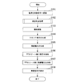
図13は、図12のステップS102の雑音低減処理の流れを示したフローチャートである。図13では、雑音低減部12aが、映像信号SINのうち1フレームの画像についてノイズ低減する処理について説明する。
まず、ノイズ量検出部32は、ノイズ量αを算出する(ステップS201)。次に、フレーム間ノイズ低減部33は、当該フレーム内のすべての画素においてフレーム間ノイズを低減する(ステップS202)。次に、水平方向ノイズ低減部60は、対象画素の水平方向のノイズを低減する(ステップS203)。
FIG. 13 is a flowchart showing the flow of the noise reduction process in step S102 of FIG. FIG. 13 illustrates a process in which the noise reduction unit 12a reduces noise for an image of one frame in the video signal SIN .
First, the noise amount detection unit 32 calculates the noise amount α (step S201). Next, the interframe noise reduction unit 33 reduces interframe noise in all the pixels in the frame (step S202). Next, the horizontal noise reduction unit 60 reduces the noise in the horizontal direction of the target pixel (step S203).

次に、エッジ判定部50は対象画素が垂直エッジか否か判定する(ステップS204)。対象画素が垂直エッジの場合(ステップS204 YES)、信号選択部70は、対象画素の輝度値をそのまま選択する(ステップS205)。一方、対象画素が垂直エッジでない場合(ステップS204 YES)、信号選択部70は、水平方向のノイズ低減をした後の輝度値を示す信号を選択する(ステップS206)。   Next, the edge determination unit 50 determines whether the target pixel is a vertical edge (step S204). If the target pixel is a vertical edge (YES in step S204), the signal selection unit 70 selects the luminance value of the target pixel as it is (step S205). On the other hand, if the target pixel is not a vertical edge (YES in step S204), the signal selection unit 70 selects a signal indicating the luminance value after noise reduction in the horizontal direction (step S206).

次に、フレーム内ノイズ低減部40aは、フレーム内の各画素において選択された輝度値を示す輝度信号を有する映像信号SOUTを順次画像調整部13に出力する。以上で、本フローチャートの処理を終了する。 Next, the intra-frame noise reduction unit 40a sequentially outputs the video signal S OUT having a luminance signal indicating the luminance value selected at each pixel in the frame to the image adjustment unit 13. Above, the process of this flowchart is complete | finished.

図14は、図13のステップS201のノイズ量αの算出の流れを示したフローチャートである。同図では、所定のフレームにおけるノイズ量を算出する処理の流れについて説明する。
まず、ノイズ量検出部32は、対象画素の輝度値を示す信号を一時記憶部31から読み出す(ステップS301)。次に、ノイズ量検出部32は、対象画素の位置に相当する1フレーム前の比較画素の輝度値を示す信号と1フレーム後の比較画素の輝度値を示す信号とを一時記憶部31から読み出す(ステップS302)。
FIG. 14 is a flowchart showing a flow of calculating the noise amount α in step S201 of FIG. In the figure, the flow of processing for calculating the amount of noise in a predetermined frame will be described.
First, the noise amount detection unit 32 reads a signal indicating the luminance value of the target pixel from the temporary storage unit 31 (step S301). Next, the noise amount detection unit 32 reads from the temporary storage unit 31 a signal indicating the luminance value of the comparison pixel one frame before corresponding to the position of the target pixel and a signal indicating the luminance value of the comparison pixel after one frame. (Step S302).

次に、ノイズ量検出部32は、対象画素の輝度値が、上記一時記憶部31から読み出した3つの輝度値のうちで最大または最小であるか判定する(ステップS303)。対象画素の輝度値が最大または最小である場合(ステップS303 YES)、対象画素の輝度値と比較画素の輝度値の差の平均値を算出する(ステップS304)。一方、対象画素の輝度値が最大でも最小でもない場合(ステップS303 NO)、ノイズ量検出部32はステップS305の処理に進む。   Next, the noise amount detection unit 32 determines whether the luminance value of the target pixel is the maximum or the minimum among the three luminance values read from the temporary storage unit 31 (step S303). When the luminance value of the target pixel is maximum or minimum (YES in step S303), an average value of the difference between the luminance value of the target pixel and the luminance value of the comparison pixel is calculated (step S304). On the other hand, when the luminance value of the target pixel is neither the maximum nor the minimum (step S303 NO), the noise amount detection unit 32 proceeds to the process of step S305.

次に、ノイズ量検出部32は当該フレーム内の全ての画素で上記処理を行ったか否か判定する(ステップS305)。ノイズ量検出部32は当該フレーム内の全ての画素で上記処理を行っていない場合(ステップS305 NO)、ステップS301の処理に戻る。一方、ノイズ量検出部32は当該フレーム内の全ての画素で上記処理を行った場合(ステップS305 YES)、ノイズ量検出部32は最頻値をノイズ量αとして抽出する(ステップS306)。以上で、本フローチャートの処理を終了する。   Next, the noise amount detection unit 32 determines whether or not the above processing has been performed on all the pixels in the frame (step S305). When the noise amount detection unit 32 has not performed the above process on all the pixels in the frame (NO in step S305), the process returns to the process of step S301. On the other hand, when the noise amount detection unit 32 performs the above processing on all the pixels in the frame (YES in step S305), the noise amount detection unit 32 extracts the mode value as the noise amount α (step S306). Above, the process of this flowchart is complete | finished.

なお、本実施形態では、エッジ判定部50は、エッジ判定用比較画素として対象画素から水平方向にc画素離れた位置にある2つの画素を抽出したがこれに限ったものではない。エッジ判定部50は、エッジ判定用比較画素を対象画素から上下にそれぞれ所定の画素間隔c_2(c_2は正の整数)離れた位置にある2つの画素を抽出して、水平のエッジを検出してもよい。その場合、ノイズ低減部42は、ノイズ低減用比較画素を対象画素から上下にそれぞれ所定の画素間隔a_2(a_2は正の整数)離れた位置にある2つの画素を抽出することにより垂直方向のノイズを低減するようにしてもよい。その場合、上記画素間隔c_2は、画素間隔a_2に1を加算した値であることが好ましい。   In this embodiment, the edge determination unit 50 extracts two pixels located at a position c pixels away from the target pixel in the horizontal direction as the edge determination comparison pixels, but the present invention is not limited to this. The edge determination unit 50 extracts two pixels located at predetermined pixel intervals c_2 (c_2 is a positive integer) above and below the target pixel from the target pixel, and detects a horizontal edge. Also good. In that case, the noise reduction unit 42 extracts the noise in the vertical direction by extracting two pixels located at predetermined pixel intervals a_2 (a_2 is a positive integer) above and below the target pixel from the target pixel. May be reduced. In that case, the pixel interval c_2 is preferably a value obtained by adding 1 to the pixel interval a_2.

また、エッジ判定部50は、エッジ判定用比較画素を対象画素から斜め方向にそれぞれ所定の画素間隔c_3(c_3は正の整数)離れた位置にある2つの画素を抽出して、斜めのエッジを検出してもよい。その場合、ノイズ低減部42は、ノイズ低減用比較画素を対象画素から斜め方向にそれぞれ所定の画素間隔a_3(a_3は正の整数)離れた位置にある2つの画素を抽出することにより斜め方向のノイズを低減するようにしてもよい。その場合、上記画素間隔c_3は、画素間隔a_3に1を加算した値であることが好ましい。   In addition, the edge determination unit 50 extracts two pixels located at predetermined pixel intervals c_3 (c_3 is a positive integer) in the diagonal direction from the target pixel as the edge determination comparison pixel, and extracts the diagonal edge. It may be detected. In this case, the noise reduction unit 42 extracts the two pixels at the predetermined pixel interval a_3 (a_3 is a positive integer) in the diagonal direction from the target pixel in the noise reduction comparison pixel, thereby extracting the comparison pixel in the diagonal direction. Noise may be reduced. In that case, the pixel interval c_3 is preferably a value obtained by adding 1 to the pixel interval a_3.

以上、エッジ判定部50は、画像内のノイズ低減の対象となる対象画素と、該対象画素から予め定められた位置関係にあるエッジ判定用比較画素とに基づいて、該対象画素がエッジであるか否か判定する。そして、ノイズ低減部42は、エッジ判定部50により対象画素がエッジでないと判定された場合、対象画素と、該対象画素から予め定められた位置関係にあるノイズ低減用比較画素とに基づいて、対象画素のノイズを低減する。   As described above, the edge determination unit 50 determines that the target pixel is an edge based on the target pixel that is the target of noise reduction in the image and the edge determination comparison pixel that has a predetermined positional relationship from the target pixel. It is determined whether or not. Then, when the edge determination unit 50 determines that the target pixel is not an edge, the noise reduction unit 42 is based on the target pixel and a noise reduction comparison pixel that has a predetermined positional relationship from the target pixel. Reduce the noise of the target pixel.

これにより、第1の実施形態の雑音低減部12aは、ノイズ低減として、時間方向と空間方向とのノイズ低減を行い、エッジ部分(ここで、エッジは水平方向、垂直方向、斜め方向のことがある)では、空間方向のノイズ低減を行わず、この場合のノイズ低減は時間方向のみとなる。
その結果、雑音低減部12aは、エッジ部分をぼかすことなく、時間方向に画像のノイズを低減することができる。また、雑音低減部12aは、エッジでない部分については、時間方向と空間方向にノイズを低減することができるので、画像全体としては、エッジ部分を残したまま、ノイズを低減することができる。
Accordingly, the noise reduction unit 12a of the first embodiment performs noise reduction in the time direction and the spatial direction as noise reduction, and the edge portion (where the edge is in the horizontal direction, the vertical direction, or the diagonal direction). In other cases, noise reduction in the spatial direction is not performed, and noise reduction in this case is only in the time direction.
As a result, the noise reduction unit 12a can reduce image noise in the time direction without blurring the edge portion. Further, since the noise reduction unit 12a can reduce the noise in the time direction and the spatial direction for a portion that is not an edge, the noise can be reduced while leaving the edge portion in the entire image.

<第1の実施形態の変形例1>
また、本実施形態では、エッジ判定部50は、エッジ判定用比較画素として対象画素から水平方向にc画素間隔離れた位置にある2つの画素を抽出したが、これに限らず、対象画素から水平方向に離れた画素を3つ以上抽出してもよい。
<Variation 1 of the first embodiment>
In the present embodiment, the edge determination unit 50 extracts two pixels located at a distance of c pixel intervals in the horizontal direction from the target pixel as the edge determination comparison pixels. Three or more pixels separated in the direction may be extracted.

上記の例について、図15を用いて説明する。図15は、エッジ判定用比較画素として4つの比較画素を抽出した例を示した図である。同図において、対象画素150から向かって左方向に3画素間隔離れた位置に第1のノイズ低減用比較画素151があり、対象画素150から向かって右方向に3画素間隔離れた位置に第2のノイズ低減用比較画素152が示されている。   The above example will be described with reference to FIG. FIG. 15 is a diagram illustrating an example in which four comparison pixels are extracted as the edge determination comparison pixels. In the figure, the first noise reduction comparison pixel 151 is located at a distance of 3 pixels in the left direction from the target pixel 150, and the second noise reduction comparison pixel 151 is located at a position of 3 pixels in the right direction from the target pixel 150. The noise reduction comparison pixel 152 is shown.

また、対象画素150から向かって左方向に4画素間隔離れた位置に第1のエッジ判定用比較画素153があり、対象画素150から向かって左方向に2画素間隔離れた位置に第2のエッジ判定用比較画素154があることが示されている。また、対象画素150から向かって右方向に2画素間隔離れた位置に第3のエッジ判定用比較画素155があり、対象画素150から向かって右方向に4画素間隔離れた位置に第4のエッジ判定用比較画素156があることが示されている。
第2のエッジ判定用比較画素154と第3のエッジ判定用比較画素155のように、エッジ判定用比較画素は、対象画素を基準としてノイズ低減用比較画素の位置よりも内に位置していてもよい。
In addition, the first edge determination comparison pixel 153 is located at a distance of 4 pixels in the left direction from the target pixel 150, and the second edge is located at a position of a distance of 2 pixels in the left direction from the target pixel 150. It is shown that there is a comparison pixel 154 for determination. In addition, the third edge determination comparison pixel 155 is located at a position two pixels apart in the right direction from the target pixel 150, and the fourth edge is located at a position four pixels apart in the right direction from the target pixel 150. It is shown that there is a comparison comparison pixel 156.
Like the second edge determination comparison pixel 154 and the third edge determination comparison pixel 155, the edge determination comparison pixel is located within the position of the noise reduction comparison pixel with respect to the target pixel. Also good.

その場合、図8に示されたハイパスフィルタ部54は、ハイパスフィルタ部157に変更される。ハイパスフィルタ部157は、第1の乗算部157_1、第2の乗算部157_2と、第3の乗算部157_3と、第4の乗算部157_4と、第5の乗算部157_5と、加算部157_6を備える。   In that case, the high-pass filter unit 54 shown in FIG. 8 is changed to a high-pass filter unit 157. The high pass filter unit 157 includes a first multiplier 157_1, a second multiplier 157_2, a third multiplier 157_3, a fourth multiplier 157_4, a fifth multiplier 157_5, and an adder 157_6. .

第1の乗算部157_1は、第1のエッジ判定用比較画素153の輝度値Yp4を示す信号を受信し、輝度値Yp4を−1/4倍した値−Yp4/4を算出し、算出値−Yp4/4を示す信号を加算部157_6に出力する。
第2の乗算部157_2は、第2のエッジ判定用比較画素154の輝度値Yp3を示す信号を受信し、輝度値Yp3を−1/4倍した値−Yp3/4を算出し、算出値−Yp3/4を示す信号を加算部157_6に出力する。
The first multiplier 157_1 receives a signal indicating the luminance value Yp4 of the first edge determination comparison pixel 153, calculates a value −Yp4 / 4 obtained by multiplying the luminance value Yp4 by −1/4, and calculates a value − A signal indicating Yp4 / 4 is output to the adder 157_6.
The second multiplier 157_2 receives a signal indicating the luminance value Yp3 of the second edge determination comparison pixel 154, calculates a value −Yp3 / 4 obtained by multiplying the luminance value Yp3 by −1/4, and calculates a value − A signal indicating Yp3 / 4 is output to the adder 157_6.

第3の乗算部157_3は、対象画像150の輝度値Ycを示す信号を受信し、輝度値Ycを1倍した値Ycを算出し、算出値Ycを示す信号を加算部157_6に出力する。
第4の乗算部157_4は、第3のエッジ判定用比較画素155の輝度値Yn3を示す信号を受信し、輝度値Yn3を−1/4倍した値−Yn3/4を算出し、算出値−Yn3/4を示す信号を加算部157_6に出力する。
第5の乗算部157_5は、第4のエッジ判定用比較画素156の輝度値Yn4を示す信号を受信し、輝度値Yn4を−1/4倍した値−Yn4/4を算出し、算出値−Yn4/4を示す信号を加算部157_6に出力する。
The third multiplication unit 157_3 receives a signal indicating the luminance value Yc of the target image 150, calculates a value Yc obtained by multiplying the luminance value Yc by 1, and outputs a signal indicating the calculated value Yc to the addition unit 157_6.
The fourth multiplier 157_4 receives a signal indicating the luminance value Yn3 of the third edge determination comparison pixel 155, calculates a value −Yn3 / 4 obtained by multiplying the luminance value Yn3 by −1/4, and calculates − A signal indicating Yn3 / 4 is output to the adder 157_6.
The fifth multiplier 157_5 receives the signal indicating the luminance value Yn4 of the fourth edge determination comparison pixel 156, calculates a value −Yn4 / 4 obtained by multiplying the luminance value Yn4 by −1/4, and calculates − A signal indicating Yn4 / 4 is output to the adder 157_6.

加算部157_6は、入力された算出値−Yp4/4と、算出値−Yp3/4と、算出値Ycと、算出値−Yn3/4、算出値−Yn4/4との和(−Yp4/4−Yp3/4+Yc−Yn3/4−Yn4/4)を算出し、算出した和を示す信号を不図示の絶対値算出部55に出力する。
このように、エッジ判定用比較画素が3つ以上あっても、ハイパスフィルタ部157は、ハイパスフィルタ部157が備える乗算部により乗じられる係数の総和を0にすることにより、直流成分を除去し、ハイパスフィルタをかけることができる。
The adding unit 157_6 is a sum (-Yp4 / 4) of the input calculated value -Yp4 / 4, calculated value -Yp3 / 4, calculated value Yc, calculated value -Yn3 / 4, and calculated value -Yn4 / 4. -Yp3 / 4 + Yc-Yn3 / 4-Yn4 / 4), and a signal indicating the calculated sum is output to the absolute value calculation unit 55 (not shown).
As described above, even when there are three or more edge determination comparison pixels, the high-pass filter unit 157 removes the DC component by setting the sum of the coefficients multiplied by the multiplication unit included in the high-pass filter unit 157 to 0, High pass filter can be applied.

第1の実施形態の変形例1のエッジ判定部50は、対象画素から水平方向に離れた画素を3つ以上抽出し、抽出した3つ以上の画素に基づいてエッジを判定するので、2つの画素に基づいてエッジを判定する第1の実施形態の判定部50よりも精度良くエッジを判定することができる。   The edge determination unit 50 according to the first modification of the first embodiment extracts three or more pixels separated from the target pixel in the horizontal direction, and determines an edge based on the extracted three or more pixels. An edge can be determined with higher accuracy than the determination unit 50 according to the first embodiment that determines an edge based on a pixel.

<第1の実施形態の変形例2>
また、本実施形態では、エッジ判定部50は、エッジ判定用比較画素として、対象画素を中心として点対称に位置する画素を抽出したが、これに限ったものではない。エッジ判定部50は、エッジ判定部50により用いられる2つのエッジ判定用比較画素の間隔Dが、ノイズ低減部42により用いられる2つのノイズ低減用比較画素の間隔d以上になるようにエッジ判定用比較画素を抽出すればよい。
<Modification 2 of the first embodiment>
Further, in the present embodiment, the edge determination unit 50 extracts pixels located symmetrically with respect to the target pixel as the edge determination comparison pixel, but the present invention is not limited to this. The edge determination unit 50 performs edge determination so that the interval D between the two edge determination comparison pixels used by the edge determination unit 50 is equal to or greater than the interval d between the two noise reduction comparison pixels used by the noise reduction unit 42. What is necessary is just to extract a comparison pixel.

上記の例について、図16を用いて説明する。図16は、2つのエッジ判定用比較画素の間隔が、2つのノイズ低減用比較画素の間隔以上である例を示した図である。同図において、第1のエッジ判定用比較画素163と第2のエッジ判定用比較画素164との画素間隔Dは、第1のノイズ低減用比較画素161と第2のノイズ低減用比較画素162との画素間隔d以上であることが示されている。   The above example will be described with reference to FIG. FIG. 16 is a diagram illustrating an example in which the interval between the two edge determination comparison pixels is equal to or greater than the interval between the two noise reduction comparison pixels. In the drawing, the pixel interval D between the first edge determination comparison pixel 163 and the second edge determination comparison pixel 164 is equal to the first noise reduction comparison pixel 161 and the second noise reduction comparison pixel 162. It is shown that the pixel interval is greater than or equal to d.

また、対象画素160は、2つのエッジ判定用比較画素(163、164)の間にあることが示されている。エッジ判定部50は、対象画素が2つのエッジ判定用比較画素の間にあることにより、対象画素のエッジを抽出することができる。   Further, it is shown that the target pixel 160 is between two edge determination comparison pixels (163, 164). The edge determination unit 50 can extract the edge of the target pixel when the target pixel is between the two edge determination comparison pixels.

図17は、映像信号の信号強度と周波数の関係の一例が示された図である。同図において、所定の映像信号における信号強度165が示されている。図16に示されたノイズ低減用比較画素(161、162)を用いたノイズ低減により低減する周波数帯域166と、図16に示されたエッジ判定用比較画素(163、164)を用いたハイパスフィルタ後の周波数帯域167とが示されている。   FIG. 17 is a diagram showing an example of the relationship between the signal strength of the video signal and the frequency. In the figure, a signal intensity 165 in a predetermined video signal is shown. A frequency band 166 reduced by noise reduction using the noise reduction comparison pixels (161, 162) shown in FIG. 16, and a high-pass filter using the edge determination comparison pixels (163, 164) shown in FIG. A later frequency band 167 is shown.

エッジ判定部50は、ノイズ低減により低減される周波数帯域166にエッジの信号があるか否か判定する必要があるので、ハイパスフィルタ後の周波数帯域167がノイズ低減により低減される周波数帯域を含んでいればよい。その場合、ノイズ低減により低減する周波数帯域166の下限周波数は、ハイパスフィルタ後の周波数帯域167の下限周波数以上となる。   Since the edge determination unit 50 needs to determine whether or not there is an edge signal in the frequency band 166 reduced by noise reduction, the frequency band 167 after the high-pass filter includes the frequency band reduced by noise reduction. It only has to be. In that case, the lower limit frequency of the frequency band 166 reduced by noise reduction is equal to or higher than the lower limit frequency of the frequency band 167 after the high-pass filter.

本実施形態では、1次元のハイパスフィルタを用いるので、上記の条件を満たすためには、2つのエッジ判定用比較画素の間隔Dは、2つのノイズ低減用比較画素の間隔d以上であればよいこととなる。従って、エッジ判定部50は、エッジ判定部50により用いられる2つのエッジ判定用比較画素の間隔Dが、ノイズ低減部42により用いられる2つのノイズ低減用比較画素の間隔d以上になるようにエッジ判定用比較画素を抽出する。   In this embodiment, since a one-dimensional high-pass filter is used, in order to satisfy the above condition, the interval D between the two edge determination comparison pixels may be equal to or greater than the interval d between the two noise reduction comparison pixels. It will be. Accordingly, the edge determination unit 50 performs edge adjustment so that the interval D between the two edge determination comparison pixels used by the edge determination unit 50 is equal to or greater than the interval d between the two noise reduction comparison pixels used by the noise reduction unit 42. A comparison pixel for determination is extracted.

<第2の実施形態>
次に、本発明の第2の実施形態について説明する。第1の実施形態の表示装置10aの雑音低減部12aは、垂直方向のエッジでない画素に対して水平方向のノイズを除去した。第2の実施形態の表示装置10bの雑音低減部12bは、垂直方向のエッジでない画素に対して水平方向のノイズを除去し、水平方向のノイズを除去した画像データに対して、更に水平方向のエッジでない画素に対して垂直方向のノイズを除去する。これにより、雑音低減部12bはエッジの画素をぼかさないまま、水平方向と垂直方向の両方のノイズを除去することができるので、エッジの画素をぼかさないまま第1の実施形態における雑音低減部12aより更にノイズを除去することができる。
<Second Embodiment>
Next, a second embodiment of the present invention will be described. The noise reduction unit 12a of the display device 10a according to the first embodiment removes horizontal noise from pixels that are not vertical edges. The noise reduction unit 12b of the display device 10b according to the second embodiment removes horizontal noise from pixels that are not edges in the vertical direction, and further performs horizontal correction on image data from which horizontal noise has been removed. Remove noise in the vertical direction for pixels that are not edges. Accordingly, the noise reduction unit 12b can remove both horizontal and vertical noises without blurring the edge pixels, so the noise reduction unit 12a in the first embodiment without blurring the edge pixels. Noise can be further removed.

図18は、第2の実施形態における表示装置10bの機能ブロック図である。なお、図1と共通する要素には同一の符号を付し、その具体的な説明を省略する。
図18の表示装置10bの構成は、図1の表示装置10aの構成に対して、雑音低減部12aが、雑音低減部12bに変更されたものとなっている。
FIG. 18 is a functional block diagram of the display device 10b according to the second embodiment. Elements common to those in FIG. 1 are denoted by the same reference numerals, and detailed description thereof is omitted.
The configuration of the display device 10b in FIG. 18 is such that the noise reduction unit 12a is changed to a noise reduction unit 12b with respect to the configuration of the display device 10a in FIG.

図19は、第2の実施形態における雑音低減部12bの機能ブロック図である。なお、図3と共通する要素には同一の符号を付し、その具体的な説明を省略する。
図19の雑音低減部12bの構成は、図3の雑音低減部12aの構成に対して、第2のフレーム内ノイズ低減部40bが追加されたものになっている。
FIG. 19 is a functional block diagram of the noise reduction unit 12b in the second embodiment. In addition, the same code | symbol is attached | subjected to the element which is common in FIG. 3, and the specific description is abbreviate | omitted.
The configuration of the noise reduction unit 12b in FIG. 19 is obtained by adding a second intra-frame noise reduction unit 40b to the configuration of the noise reduction unit 12a in FIG.

フレーム内ノイズ低減部40aは、水平方向のノイズを低減した輝度信号を有する映像信号を順次第2のフレーム内ノイズ低減部40bに出力する。
第2のフレーム内ノイズ低減部40bは、フレーム内ノイズ低減部40aから出力された水平方向のノイズを低減した輝度信号を有する映像信号を受信し、その映像信号に含まれる輝度信号に対して垂直方向のノイズを低減し、垂直方向のノイズを低減した映像信号SOUTを画像調整部13に出力する。
The intra-frame noise reduction unit 40a sequentially outputs video signals having luminance signals with reduced horizontal noise to the second intra-frame noise reduction unit 40b.
The second intra-frame noise reduction unit 40b receives a video signal having a luminance signal with reduced horizontal noise output from the intra-frame noise reduction unit 40a, and is perpendicular to the luminance signal included in the video signal. The video signal S OUT in which the noise in the direction is reduced and the noise in the vertical direction is reduced is output to the image adjustment unit 13.

第2のフレーム内ノイズ低減部40bは、第2のエッジ判定部80と、ノイズ低減部42bとを備える。図20を用いて、第2のエッジ判定部80について説明する。図20は、第2の実施形態における第2のエッジ判定部80の機能ブロック図である。なお、図8と共通する要素には同一の符号を付し、その具体的な説明を省略する。
図20の第2のエッジ判定部80の構成は、図8のエッジ判定部50の構成に対して、第1の比較画素抽出部51が第5の比較画素抽出部81に変更され、対象画素抽出部52が対象画素抽出部82に変更され、第2の比較画素抽出部53が第6の比較画素抽出部83に変更されたものになっている。
The second intra-frame noise reduction unit 40b includes a second edge determination unit 80 and a noise reduction unit 42b. The second edge determination unit 80 will be described with reference to FIG. FIG. 20 is a functional block diagram of the second edge determination unit 80 in the second embodiment. In addition, the same code | symbol is attached | subjected to the element which is common in FIG. 8, and the specific description is abbreviate | omitted.
The configuration of the second edge determination unit 80 in FIG. 20 is different from the configuration of the edge determination unit 50 in FIG. 8 in that the first comparison pixel extraction unit 51 is changed to a fifth comparison pixel extraction unit 81 and the target pixel is changed. The extraction unit 52 is changed to the target pixel extraction unit 82, and the second comparison pixel extraction unit 53 is changed to the sixth comparison pixel extraction unit 83.

第5の比較画素抽出部81は、フレーム内ノイズ低減部40aから出力された水平方向のノイズを低減した映像信号を受信し、対象画素から向かって上に画素間隔e離れた画素の輝度値Yu2を示す輝度信号を抽出する(eは正の整数)。   The fifth comparison pixel extraction unit 81 receives the video signal with reduced horizontal noise output from the intra-frame noise reduction unit 40a, and the luminance value Yu2 of the pixels that are spaced apart by the pixel interval e upward from the target pixel. (E is a positive integer).

具体的には、例えば、第5の比較画素抽出部81は、入力信号を遅延させる遅延回路を備える。第1の比較画素抽出部51の遅延回路は、フレーム間ノイズ低減部33から入力されたフレーム間ノイズ低減後の輝度信号を、フレームの左端(i=1,j=1)の画素から対象画素から垂直方向にe画素だけ上にある画素までの画素間隔に相当する遅延時間だけ遅らせる。   Specifically, for example, the fifth comparison pixel extraction unit 81 includes a delay circuit that delays the input signal. The delay circuit of the first comparison pixel extraction unit 51 converts the luminance signal after the inter-frame noise reduction input from the inter-frame noise reduction unit 33 from the pixel at the left end (i = 1, j = 1) of the frame to the target pixel. And a delay time corresponding to the pixel interval from the pixel to the pixel that is e pixels above in the vertical direction.

そして、第5の比較画素抽出部81は、抽出した輝度値Yu2を示す輝度信号を第1の乗算部54_1に出力する。また、第5の比較画素抽出部81は、遅延回路により水平方向のノイズを低減した映像信号を遅らせることにより生成された輝度信号を第5の遅延輝度信号として対象画素抽出部52に出力する。   Then, the fifth comparison pixel extraction unit 81 outputs a luminance signal indicating the extracted luminance value Yu2 to the first multiplication unit 54_1. In addition, the fifth comparison pixel extraction unit 81 outputs a luminance signal generated by delaying the video signal whose horizontal noise is reduced by the delay circuit to the target pixel extraction unit 52 as a fifth delayed luminance signal.

対象画素抽出部82は、第5の比較画素抽出部81から入力された第5の遅延輝度信号から対象画素の輝度値Ycを示す輝度信号を抽出し、その対象画素の輝度値Ycを示す輝度信号をハイパスフィルタ部54の第2の乗算部54_2に出力する。   The target pixel extraction unit 82 extracts a luminance signal indicating the luminance value Yc of the target pixel from the fifth delayed luminance signal input from the fifth comparison pixel extraction unit 81, and the luminance indicating the luminance value Yc of the target pixel. The signal is output to the second multiplication unit 54_2 of the high-pass filter unit 54.

具体的には、例えば、対象画素抽出部82は、入力信号を遅延させる遅延回路を備える。対象画素抽出部82の遅延回路は、第1の比較画素抽出部51から入力された第1の遅延輝度信号をe画素間隔に相当する時間だけ遅らせることにより、対象画素の輝度値Ycを示す輝度信号を抽出する。
また、対象画素抽出部52は、第5の遅延輝度信号を遅らせることにより生成された第6の遅延輝度信号を、第6の比較画素抽出部83に出力する。
Specifically, for example, the target pixel extraction unit 82 includes a delay circuit that delays an input signal. The delay circuit of the target pixel extraction unit 82 delays the first delayed luminance signal input from the first comparison pixel extraction unit 51 by a time corresponding to the e pixel interval, thereby indicating the luminance value Yc of the target pixel. Extract the signal.
Further, the target pixel extraction unit 52 outputs the sixth delayed luminance signal generated by delaying the fifth delayed luminance signal to the sixth comparison pixel extracting unit 83.

第6の比較画素抽出部83は、対象画素抽出部52から出力された第6の遅延輝度信号を受信し、対象画素から向かって下に画素間隔e離れた画素の度値Yd2を示す輝度信号を抽出する。そして、第6の比較画素抽出部83は、抽出した輝度値Yd2を示す輝度信号を第3の乗算部54_3に出力する。   The sixth comparison pixel extraction unit 83 receives the sixth delayed luminance signal output from the target pixel extraction unit 52, and indicates a luminance signal indicating the degree value Yd2 of the pixels that are spaced apart by the pixel interval e downward from the target pixel. To extract. Then, the sixth comparison pixel extraction unit 83 outputs a luminance signal indicating the extracted luminance value Yd2 to the third multiplication unit 54_3.

具体的には、例えば、第6の比較画素抽出部83は、入力信号を遅延させる遅延回路を備える。第6の比較画素抽出部83の遅延回路は、対象画素抽出部52から入力された第6の遅延輝度信号を対象画素から垂直方向にe画素だけ下にある画素までの画素間隔に相当する時間だけ遅らせることにより、エッジ判定用比較画素の輝度値Yd2を示す輝度信号を抽出する。   Specifically, for example, the sixth comparison pixel extraction unit 83 includes a delay circuit that delays the input signal. The delay circuit of the sixth comparison pixel extracting unit 83 is a time corresponding to a pixel interval from the target pixel to the pixel that is e pixels below in the vertical direction from the target pixel. The luminance signal indicating the luminance value Yd2 of the edge determination comparison pixel is extracted by delaying the signal by the delay time.

図21は、第2の実施形態におけるエッジ判定用比較画素とノイズ低減用比較画素の関係について説明するための図である。同図において、対象画素210と第1のノイズ低減用比較画素213との画素間隔または第2のノイズ低減用比較画素214との画素間隔はbであることが示されている。
また、対象画素210と第1のエッジ判定用比較画素211または第2のエッジ判定用比較画素212との画素間隔eは、上記画素間隔bに1が加算された値であることが示されている。
FIG. 21 is a diagram for explaining the relationship between the edge determination comparison pixel and the noise reduction comparison pixel in the second embodiment. In the figure, the pixel interval between the target pixel 210 and the first noise reduction comparison pixel 213 or the pixel interval between the second noise reduction comparison pixel 214 is b.
In addition, it is indicated that the pixel interval e between the target pixel 210 and the first edge determination comparison pixel 211 or the second edge determination comparison pixel 212 is a value obtained by adding 1 to the pixel interval b. Yes.

第1の乗算部54_1は、第1のエッジ判定用比較画素211の輝度値Yu2を示す信号を受信し、輝度値Yu2を−1/2倍し、算出値−1/2×Yu2を示す信号を加算部54_4に出力する。
第2の乗算部54_2は、対象画素の輝度値Ycを示す信号を受信し、輝度値Ycに1倍し、算出値Ycを示す信号を加算部54_4に出力する。
The first multiplier 54_1 receives the signal indicating the luminance value Yu2 of the first edge determination comparison pixel 211, multiplies the luminance value Yu2 by -1/2, and indicates the calculated value -1 / 2 × Yu2. Is output to the adder 54_4.
The second multiplication unit 54_2 receives the signal indicating the luminance value Yc of the target pixel, multiplies the luminance value Yc by 1, and outputs a signal indicating the calculated value Yc to the addition unit 54_4.

第3の乗算部54_3は、第2のエッジ判定用比較画素212の輝度値Yd2を示す信号を受信し、輝度値Yd2に−1/2倍し、算出値−1/2×Yd2を示す信号を加算部54_4に出力する。
加算部54_4は、第1の乗算部54_1から入力された算出値−1/2×Yu2と、第2の乗算部54_2から入力された算出値Ycと、第3の乗算部54_3から入力された算出値−1/2×Yd2との和を算出し、算出された和を示す信号を絶対値算出部55に出力する。
The third multiplier 54_3 receives the signal indicating the luminance value Yd2 of the second edge determination comparison pixel 212, multiplies the luminance value Yd2 by -1/2, and indicates the calculated value -1 / 2 × Yd2. Is output to the adder 54_4.
The adder 54_4 receives the calculated value −1 / 2 × Yu2 input from the first multiplier 54_1, the calculated value Yc input from the second multiplier 54_2, and the third multiplier 54_3. The sum of the calculated value −½ × Yd 2 is calculated, and a signal indicating the calculated sum is output to the absolute value calculating unit 55.

最大最小判定部64_1は、第1のノイズ低減用比較画素213の輝度値Yu1を示す信号を受信する。また、最大最小判定部64_1は、対象画素210の輝度値Ycを示す信号を受信する。また、最大最小判定部64_1は、第2のノイズ低減用比較画素214の輝度値Yd1を示す信号を受信する。   The maximum / minimum determination unit 64_1 receives a signal indicating the luminance value Yu1 of the first noise reduction comparison pixel 213. In addition, the maximum / minimum determination unit 64_1 receives a signal indicating the luminance value Yc of the target pixel 210. Further, the maximum / minimum determination unit 64_1 receives a signal indicating the luminance value Yd1 of the second noise reduction comparison pixel 214.

続いて、ノイズ低減部42bの処理の概要について説明する。ノイズ低減部42bは、フレーム内ノイズ低減部40aから出力された水平方向のノイズを低減した画像データを受信する。また、ノイズ低減部42bは、ノイズ量検出部32から出力されたノイズ量αを示す信号を受信する。そして、ノイズ低減部42bは、対象画素と該対象画素から予め定められた位置関係にあるノイズ低減用比較画素の輝度値とノイズ量αとに基づいて、対象画素の垂直方向のノイズを低減する。   Next, an outline of the processing of the noise reduction unit 42b will be described. The noise reduction unit 42b receives the image data with reduced horizontal noise output from the intra-frame noise reduction unit 40a. Further, the noise reduction unit 42b receives a signal indicating the noise amount α output from the noise amount detection unit 32. Then, the noise reduction unit 42b reduces the noise in the vertical direction of the target pixel based on the luminance value and the noise amount α of the target pixel and the noise reduction comparison pixel that is in a predetermined positional relationship from the target pixel. .

ノイズ低減部42bは、第2のエッジ判定部80から出力された判定結果を示す信号を受信し、その判定結果を示す信号が対象画素がエッジでないことを示す信号(例えば、0を示す信号)の場合、対象画素の垂直方向のノイズを低減した映像信号SOUTを画像調整部13に出力する。
一方、ノイズ低減部42bは、判定結果を示す信号が対象画素がエッジであることを示す信号(例えば、1を示す信号)の場合、フレーム内ノイズ低減部40aから入力された水平方向のノイズを低減した画像データをそのまま映像信号SOUTとして画像調整部13に出力する。
The noise reduction unit 42b receives the signal indicating the determination result output from the second edge determination unit 80, and the signal indicating the determination result indicates that the target pixel is not an edge (for example, a signal indicating 0). In this case, the video signal S OUT in which the noise in the vertical direction of the target pixel is reduced is output to the image adjustment unit 13.
On the other hand, when the signal indicating the determination result is a signal indicating that the target pixel is an edge (for example, a signal indicating 1), the noise reduction unit 42b receives the horizontal noise input from the intra-frame noise reduction unit 40a. The reduced image data is output as it is to the image adjustment unit 13 as the video signal SOUT .

続いて、ノイズ低減部42bの処理の詳細について説明する。ノイズ低減部42bは、垂直方向ノイズ低減部90と、信号選択部100とを備える。
図22を用いて、垂直方向ノイズ低減部90の処理について説明する。図22は、第2の実施形態における垂直方向ノイズ低減部90の機能ブロック図である。なお、図11と共通する要素には同一の符号を付し、その具体的な説明を省略する。
Next, details of the processing of the noise reduction unit 42b will be described. The noise reduction unit 42 b includes a vertical noise reduction unit 90 and a signal selection unit 100.
The process of the vertical noise reduction unit 90 will be described with reference to FIG. FIG. 22 is a functional block diagram of the vertical noise reduction unit 90 in the second embodiment. In addition, the same code | symbol is attached | subjected to the element which is common in FIG. 11, and the specific description is abbreviate | omitted.

垂直方向ノイズ低減部90は、第7の比較画素抽出部91と、対象画素抽出部92と、第8の比較画素抽出部93と、ノイズ低減部64とを備える。
第7の比較画素抽出部91は、フレーム内ノイズ低減部40aから入力された水平方向のノイズを低減した映像信号を受信し、その映像信号に含まれる輝度信号から対象画素から向かって上方向にb画素間隔(bは正の整数)離れた第1のノイズ低減用比較画素の輝度値Yp4を示す輝度信号を抽出する。
The vertical noise reduction unit 90 includes a seventh comparison pixel extraction unit 91, a target pixel extraction unit 92, an eighth comparison pixel extraction unit 93, and a noise reduction unit 64.
The seventh comparison pixel extraction unit 91 receives the video signal with reduced horizontal noise input from the intra-frame noise reduction unit 40a, and moves upward from the luminance signal included in the video signal toward the target pixel. A luminance signal indicating the luminance value Yp4 of the first noise reduction comparison pixel separated by b pixel intervals (b is a positive integer) is extracted.

具体的には、例えば、第7の比較画素抽出部91は、入力信号を遅延させる遅延回路を備える。第7の比較画素抽出部91の遅延回路は、フレーム内ノイズ低減部40aから入力された水平方向のノイズを低減した映像信号に含まれる輝度信号を、フレームの左端(i=1,j=1)の画素から対象画素から垂直方向に向かってb画素だけ上の画素までの画素間隔に相当する遅延時間だけ遅らせる。   Specifically, for example, the seventh comparison pixel extraction unit 91 includes a delay circuit that delays the input signal. The delay circuit of the seventh comparison pixel extraction unit 91 converts the luminance signal included in the video signal with reduced horizontal noise input from the intra-frame noise reduction unit 40a to the left end (i = 1, j = 1) of the frame. ) From the target pixel in the vertical direction from the target pixel by a delay time corresponding to the pixel interval from the pixel up by b pixels.

第7の比較画素抽出部91は、抽出した輝度値Yp4を示す輝度信号をノイズ低減部64が備える最大最小判定部64_1に出力する。また、第7の比較画素抽出部91は、遅延回路により遅延させたフレーム間ノイズ低減後の輝度信号を遅らせることにより生成された輝度信号を第7の遅延輝度信号としてを対象画素抽出部92に出力する。   The seventh comparison pixel extraction unit 91 outputs a luminance signal indicating the extracted luminance value Yp4 to the maximum / minimum determination unit 64_1 included in the noise reduction unit 64. In addition, the seventh comparison pixel extraction unit 91 sets the luminance signal generated by delaying the luminance signal after inter-frame noise reduction delayed by the delay circuit as the seventh delayed luminance signal to the target pixel extraction unit 92. Output.

対象画素抽出部92は、第7の比較画素抽出部91から入力された第7の遅延輝度信号から対象画素の輝度値Ycを示す輝度信号を抽出し、その対象画素の輝度値Ycを示す輝度信号をノイズ低減部64が備える最大最小判定部64_1、加算部64_2、減算部64_3および信号切替部64_4と、信号選択部100とに出力する。   The target pixel extraction unit 92 extracts a luminance signal indicating the luminance value Yc of the target pixel from the seventh delayed luminance signal input from the seventh comparison pixel extraction unit 91, and the luminance indicating the luminance value Yc of the target pixel The signal is output to the maximum / minimum determination unit 64_1, the addition unit 64_2, the subtraction unit 64_3, the signal switching unit 64_4, and the signal selection unit 100 included in the noise reduction unit 64.

具体的には、例えば、対象画素抽出部92は、入力信号を遅延させる遅延回路を備える。対象画素抽出部92の遅延回路は、第7の比較画素抽出部91から入力された第7の遅延輝度信号を垂直方向にb画素間隔に相当する時間だけ遅らせることにより、対象画素の輝度値Ycを示す輝度信号を抽出する。そして、対象画素抽出部92は、遅延回路により第7の遅延輝度信号を遅らせることにより生成された輝度信号を第8の遅延輝度信号として、第8の比較画素抽出部93に出力する。   Specifically, for example, the target pixel extraction unit 92 includes a delay circuit that delays an input signal. The delay circuit of the target pixel extraction unit 92 delays the seventh delayed luminance signal input from the seventh comparison pixel extraction unit 91 in the vertical direction by a time corresponding to the b pixel interval, thereby the luminance value Yc of the target pixel. Is extracted. Then, the target pixel extraction unit 92 outputs the luminance signal generated by delaying the seventh delayed luminance signal by the delay circuit to the eighth comparison pixel extraction unit 93 as an eighth delayed luminance signal.

第8の比較画素抽出部93は、対象画素抽出部92から入力された第8の遅延輝度信号を用いて、対象画素から向かって下方向にb画素だけ離れた第8のノイズ低減用比較画素の輝度値Yn4を示す輝度信号を抽出する。   The eighth comparison pixel extraction unit 93 uses the eighth delayed luminance signal input from the target pixel extraction unit 92 to provide an eighth noise reduction comparison pixel that is separated by b pixels downward from the target pixel. The luminance signal indicating the luminance value Yn4 is extracted.

具体的には、例えば、第8の比較画素抽出部93は、入力信号を遅延させる遅延回路を備える。第8の比較画素抽出部93の遅延回路は、対象画素抽出部92から入力された第8の遅延輝度信号を垂直方向にb画素間隔に相当する時間だけ遅らせることにより、ノイズ低減用比較画素の輝度値Yn4を示す輝度信号を抽出する。
そして、第8の比較画素抽出部93は、抽出した輝度値Yn4を示す輝度信号をノイズ低減部64の最大最小判定部64_1に出力する。
Specifically, for example, the eighth comparison pixel extraction unit 93 includes a delay circuit that delays the input signal. The delay circuit of the eighth comparison pixel extraction unit 93 delays the eighth delayed luminance signal input from the target pixel extraction unit 92 by a time corresponding to the b pixel interval in the vertical direction, thereby reducing the noise reduction comparison pixel. A luminance signal indicating the luminance value Yn4 is extracted.
Then, the eighth comparison pixel extraction unit 93 outputs a luminance signal indicating the extracted luminance value Yn4 to the maximum / minimum determination unit 64_1 of the noise reduction unit 64.

信号選択部100は、第2のエッジ判定部80から入力された判定結果を示す信号が水平エッジであることを示す信号(例えば、1を示す信号)の場合、信号選択部100は、対象画素抽出部92から入力された対象画素の輝度値Ycを示す信号を選択する。
一方、信号選択部100は、判定結果を示す信号が水平エッジでないことを示す信号(例えば、0を示す信号)の場合、信号切替部64_4から入力された垂直方向のノイズ低減をした後の輝度値を示す信号を選択する。
When the signal indicating the determination result input from the second edge determination unit 80 is a signal indicating a horizontal edge (for example, a signal indicating 1), the signal selection unit 100 determines that the signal selection unit 100 A signal indicating the luminance value Yc of the target pixel input from the extraction unit 92 is selected.
On the other hand, in the case where the signal indicating the determination result is a signal indicating that the determination result is not a horizontal edge (for example, a signal indicating 0), the signal selection unit 100 performs luminance reduction after noise reduction in the vertical direction input from the signal switching unit 64_4. Select the signal that indicates the value.

信号選択部100は、所定のフレームの全ての画素において入力された2つの輝度値を示す信号の選択が終了すると、選択した輝度値を示す輝度信号を有する当該フレーム分の映像信号SOUTを画像調整部13に出力する。 When the selection of the signal indicating the two luminance values input in all the pixels of the predetermined frame is completed, the signal selection unit 100 displays the video signal S OUT for the frame having the luminance signal indicating the selected luminance value as an image. Output to the adjustment unit 13.

本実施形態の表示装置10bの処理の流れは、図12に示したフローチャートと同一であるので、その処理の説明を省略する。
図23は、図12のステップS102に示された第2の実施形態における雑音低減処理の流れを示したフローチャートである。ステップS401からステップS406までの処理は図13のステップS201からステップS206までの処理と同一であるので、その説明を省略する。
Since the processing flow of the display device 10b of the present embodiment is the same as the flowchart shown in FIG. 12, the description of the processing is omitted.
FIG. 23 is a flowchart showing the flow of noise reduction processing in the second embodiment shown in step S102 of FIG. Since the processing from step S401 to step S406 is the same as the processing from step S201 to step S206 in FIG. 13, the description thereof is omitted.

次に、フレーム内ノイズ低減部40aは、フレーム内ノイズ低減部40aは、フレーム内の各画素において選択された輝度値を示す輝度信号を有する映像信号を順次第2のフレーム内ノイズ低減部40bに出力する(ステップS407)。
次に、垂直方向ノイズ低減部90は、対象画素の垂直方向のノイズを低減する(ステップS408)。
Next, the intra-frame noise reduction unit 40a sequentially sends the video signal having the luminance signal indicating the luminance value selected at each pixel in the frame to the second intra-frame noise reduction unit 40b. Output (step S407).
Next, the vertical noise reduction unit 90 reduces the vertical noise of the target pixel (step S408).

次に、第2のエッジ判定部80は、対象画素が水平エッジか否か判定する(ステップS409)。対象画素が水平エッジである場合(ステップS409 YES)、信号選択部100は、対象画素の輝度値をそのまま選択する(ステップS410)。一方、対象画素が水平エッジでない場合、信号選択部100は、垂直方向のノイズ低減をした後の輝度値を選択する(ステップS411)。   Next, the second edge determination unit 80 determines whether or not the target pixel is a horizontal edge (step S409). When the target pixel is a horizontal edge (YES in step S409), the signal selection unit 100 selects the luminance value of the target pixel as it is (step S410). On the other hand, when the target pixel is not a horizontal edge, the signal selection unit 100 selects a luminance value after noise reduction in the vertical direction (step S411).

次に、第2のフレーム内ノイズ低減部40bは、フレーム内の各画素において選択された輝度値を示す輝度信号を有する映像信号SOUTを順次画像調整部13に出力する(ステップS413)。以上で、本フローチャートの処理を終了する。 Next, the second intra-frame noise reduction unit 40b sequentially outputs the video signal S OUT having a luminance signal indicating the luminance value selected in each pixel in the frame to the image adjustment unit 13 (step S413). Above, the process of this flowchart is complete | finished.

以上、本実施形態の雑音低減部12bは、垂直方向のエッジでない画素に対して水平方向のノイズを除去し、水平方向のノイズを除去した画像データに対して、更に水平方向のエッジでない画素に対して垂直方向のノイズを除去する。これにより、雑音低減部12bはエッジの画素をぼかさないまま、水平方向と垂直方向の両方のノイズを除去することができるので、エッジの画素をぼかさないまま第1の実施形態における雑音低減部12aより更にノイズを除去することができる。   As described above, the noise reduction unit 12b of the present embodiment removes horizontal noise from pixels that are not vertical edges, and further converts pixels that are not horizontal edges to image data from which horizontal noise has been removed. On the other hand, noise in the vertical direction is removed. Accordingly, the noise reduction unit 12b can remove both horizontal and vertical noises without blurring the edge pixels, so the noise reduction unit 12a in the first embodiment without blurring the edge pixels. Noise can be further removed.

なお、本実施形態では、雑音低減部12bは、水平方向のノイズを低減した後に垂直方向のノイズを低減したが、これに限らず、ノイズ低減する順番は逆でもよく、雑音低減部12bは、垂直方向のノイズ除去をした後に水平方向のノイズを除去してもよい。   In this embodiment, the noise reduction unit 12b reduces the noise in the vertical direction after reducing the noise in the horizontal direction. However, the noise reduction unit 12b is not limited thereto, and the noise reduction order may be reversed. The noise in the horizontal direction may be removed after removing the noise in the vertical direction.

また、両実施形態において、雑音低減部(12a、12b)は、映像信号SINを構成する輝度信号Yに対してノイズ低減処理を行ったがこれに限らず、色差信号(Cb、Cr)に対してノイズ低減処理を行ってもよい。
その場合、ノイズ低減部(42、42b)が対象画素の色差信号に対してノイズ低減を行う場合、エッジ判定用比較画素と対象画素との画素間隔は、ノイズ判定用比較画素と対象画素との画素間隔に2を加算した値が好ましい。
In both embodiments, the noise reduction unit (12a, 12b) performs the noise reduction process on the luminance signal Y constituting the video signal SIN . However, the present invention is not limited to this, and the color difference signal (Cb, Cr) On the other hand, noise reduction processing may be performed.
In this case, when the noise reduction unit (42, 42b) performs noise reduction on the color difference signal of the target pixel, the pixel interval between the edge determination comparison pixel and the target pixel is the difference between the noise determination comparison pixel and the target pixel. A value obtained by adding 2 to the pixel interval is preferable.

また、両実施形態において、エッジ判定部50または第2のエッジ判定部80は、1次元のハイパスフィルタを掛けたが、これに限らず、2次元のハイパスフィルタを掛けてもよい。その場合、エッジ判定部50または第2のエッジ判定部80は、対称画素を含む2次元画像領域の画素(例えば、3画素×3画素)を抽出し、抽出された画素の領域に相当する2次元カーネルを(例えば、3×3)を畳み込むことにより、ハイパスフィルタをかけてエッジを抽出してもよい。このとき、2次元カーネルを構成する各値の総和は0にする。   In both embodiments, the edge determination unit 50 or the second edge determination unit 80 is applied with a one-dimensional high-pass filter, but is not limited thereto, and may be applied with a two-dimensional high-pass filter. In that case, the edge determination unit 50 or the second edge determination unit 80 extracts a pixel (for example, 3 pixels × 3 pixels) of a two-dimensional image region including a symmetric pixel, and 2 corresponding to the extracted pixel region. Edges may be extracted by applying a high-pass filter by convolving the dimensional kernel (eg, 3 × 3). At this time, the sum of the values constituting the two-dimensional kernel is set to zero.

また、本実施形態の雑音低減部(12a、12b)の各処理を実行するためのプログラムをコンピュータ読み取り可能な記録媒体に記録して、当該記録媒体に記録されたプログラムをコンピュータシステムに読み込ませ、実行することにより、雑音低減部(12a、12b)に係る上述した種々の処理を行ってもよい。   Further, a program for executing each process of the noise reduction unit (12a, 12b) of the present embodiment is recorded on a computer-readable recording medium, and the program recorded on the recording medium is read into a computer system, By executing, the above-described various processes related to the noise reduction units (12a, 12b) may be performed.

なお、ここでいう「コンピュータシステム」とは、OSや周辺機器等のハードウェアを含むものであってもよい。また、「コンピュータシステム」は、WWWシステムを利用している場合であれば、ホームページ提供環境(あるいは表示環境)も含むものとする。また、「コンピュータ読み取り可能な記録媒体」とは、フレキシブルディスク、光磁気ディスク、ROM、フラッシュメモリ等の書き込み可能な不揮発性メモリ、CD−ROM等の可搬媒体、コンピュータシステムに内蔵されるハードディスク等の記憶装置のことをいう。   Here, the “computer system” may include an OS and hardware such as peripheral devices. Further, the “computer system” includes a homepage providing environment (or display environment) if a WWW system is used. The “computer-readable recording medium” means a flexible disk, a magneto-optical disk, a ROM, a writable nonvolatile memory such as a flash memory, a portable medium such as a CD-ROM, a hard disk built in a computer system, etc. This is a storage device.

さらに「コンピュータ読み取り可能な記録媒体」とは、インターネット等のネットワークや電話回線等の通信回線を介してプログラムが送信された場合のサーバやクライアントとなるコンピュータシステム内部の揮発性メモリ(例えばDRAM(Dynamic Random Access Memory))のように、一定時間プログラムを保持しているものも含むものとする。また、上記プログラムは、このプログラムを記憶装置等に格納したコンピュータシステムから、伝送媒体を介して、あるいは、伝送媒体中の伝送波により他のコンピュータシステムに伝送されてもよい。ここで、プログラムを伝送する「伝送媒体」は、インターネット等のネットワーク(通信網)や電話回線等の通信回線(通信線)のように情報を伝送する機能を有する媒体のことをいう。また、上記プログラムは、前述した機能の一部を実現するためのものであっても良い。さらに、前述した機能をコンピュータシステムにすでに記録されているプログラムとの組み合わせで実現できるもの、いわゆる差分ファイル(差分プログラム)であっても良い。     Further, the “computer-readable recording medium” refers to a volatile memory (for example, DRAM (Dynamic) in a computer system serving as a server or a client when a program is transmitted via a network such as the Internet or a communication line such as a telephone line. Random Access Memory)) that holds a program for a certain period of time is also included. The program may be transmitted from a computer system storing the program in a storage device or the like to another computer system via a transmission medium or by a transmission wave in the transmission medium. Here, the “transmission medium” for transmitting the program refers to a medium having a function of transmitting information, such as a network (communication network) such as the Internet or a communication line (communication line) such as a telephone line. The program may be for realizing a part of the functions described above. Furthermore, what can implement | achieve the function mentioned above in combination with the program already recorded on the computer system, and what is called a difference file (difference program) may be sufficient.

以上、本発明の実施形態について図面を参照して詳述したが、具体的な構成はこの実施形態に限られるものではなく、この発明の要旨を逸脱しない範囲の設計等も含まれる。   As mentioned above, although embodiment of this invention was explained in full detail with reference to drawings, the concrete structure is not restricted to this embodiment, The design etc. of the range which does not deviate from the summary of this invention are included.

10a、10b 表示装置
11 受信部
12a、12b 雑音低減部
13 画像調整部
14 タイミング制御部
15 ソースドライバ部
16 ゲートドライバ部
17 液晶パネル部
20 液晶表示部
31 一時記憶部
32 ノイズ量検出部
33 フレーム間ノイズ低減部
40a フレーム内ノイズ低減部
40b 第2のフレーム内ノイズ低減部
42 ノイズ低減部
50 エッジ判定部
51 第1の比較画素抽出部
52、62、82、92 対象画素抽出部
53 第3の比較画素抽出部
54 ハイパスフィルタ部
54_1 第1の乗算部
54_2 第2の乗算部
54_3 第3の乗算部
54_4 加算部
55 絶対値算出部
56 判定部
60 水平方向ノイズ低減部
61 第3の比較画素抽出部
63 第4の比較画素抽出部
64 ノイズ低減部
64_1 最大最小判定部
64_2 加算部
64_3 減算部
64_4 信号切替部
70、100 信号選択部
80 第2のエッジ判定部
81 第5の比較画素抽出部
83 第6の比較画素抽出部
90 垂直方向ノイズ低減部
91 第7の比較画素抽出部
93 第8の比較画素抽出部
10a, 10b Display device 11 Reception unit 12a, 12b Noise reduction unit 13 Image adjustment unit 14 Timing control unit 15 Source driver unit 16 Gate driver unit 17 Liquid crystal panel unit 20 Liquid crystal display unit 31 Temporary storage unit 32 Noise amount detection unit 33 Between frames Noise reduction unit 40a In-frame noise reduction unit 40b Second intra-frame noise reduction unit 42 Noise reduction unit 50 Edge determination unit 51 First comparison pixel extraction unit 52, 62, 82, 92 Target pixel extraction unit 53 Third comparison Pixel extraction unit 54 High-pass filter unit 54_1 First multiplication unit 54_2 Second multiplication unit 54_3 Third multiplication unit 54_4 Addition unit 55 Absolute value calculation unit 56 Determination unit 60 Horizontal noise reduction unit 61 Third comparison pixel extraction unit 63 Fourth comparison pixel extraction unit 64 Noise reduction unit 64_1 Maximum / minimum determination unit 64_2 Adder 6 _3 subtraction unit 64_4 signal switching unit 70, 100 signal selection unit 80 second edge determination unit 81 fifth comparison pixel extraction unit 83 sixth comparison pixel extraction unit 90 vertical noise reduction unit 91 seventh comparison pixel extraction unit 93 Eighth comparison pixel extraction unit

Claims (11)

ノイズ低減の対象となる対象画素と、該対象画素から予め定められた位置関係にあるエッジ判定用比較画素とに基づいて、該対象画素がエッジであるか否か判定するエッジ判定部と、
前記エッジ判定部により前記対象画素がエッジでないと判定された場合、前記対象画素と、該対象画素から予め定められた位置関係にあるノイズ低減用比較画素とに基づいて、前記対象画素のノイズを低減するノイズ低減部と、
を備えることを特徴とする雑音低減装置。
An edge determination unit that determines whether or not the target pixel is an edge based on a target pixel that is a target for noise reduction and an edge determination comparison pixel that is in a predetermined positional relationship from the target pixel;
When the edge determination unit determines that the target pixel is not an edge, the noise of the target pixel is determined based on the target pixel and a noise reduction comparison pixel that is in a predetermined positional relationship from the target pixel. A noise reduction unit to reduce,
A noise reduction device comprising:
前記対象画素は、前記エッジ判定部により用いられる2つの前記エッジ判定用比較画素の間にあることを特徴とする請求項1に記載の雑音低減装置。   The noise reduction apparatus according to claim 1, wherein the target pixel is located between two comparison pixels for edge determination used by the edge determination unit. 前記エッジ判定部により用いられる2つの前記エッジ判定用比較画素の間隔は、前記ノイズ低減部により用いられる2つのノイズ低減用比較画素の間隔以上であることを特徴とする請求項2に記載の雑音低減装置。   The noise according to claim 2, wherein an interval between the two edge determination comparison pixels used by the edge determination unit is equal to or greater than an interval between the two noise reduction comparison pixels used by the noise reduction unit. Reduction device. 前記エッジ判定部により用いられる各エッジ判定用比較画素は、前記対象画素を基準として前記ノイズ低減部により用いられる各ノイズ低減用比較画素が位置する画素よりも外に位置することを特徴とする請求項2または請求項3に記載の雑音低減装置。   Each edge determination comparison pixel used by the edge determination unit is located outside a pixel where each noise reduction comparison pixel used by the noise reduction unit is located with the target pixel as a reference. The noise reduction device according to claim 2 or claim 3. 前記エッジ判定部により用いられる2つの前記エッジ判定用比較画素は、前記対象画素を中心として点対称の位置にあることを特徴とする請求項2から請求項4のいずれか1項に記載の雑音低減装置。   5. The noise according to claim 2, wherein the two edge determination comparison pixels used by the edge determination unit are in a point-symmetrical position with the target pixel as a center. 6. Reduction device. 前記ノイズ低減部が前記対象画素の輝度信号に対してノイズ低減を行う場合、前記エッジ判定用比較画素と前記対象画素との画素間隔は、前記ノイズ判定用比較画素と前記対象画素との画素間隔に1を加算した値であることを特徴とする請求項5に記載の雑音低減装置。   When the noise reduction unit performs noise reduction on the luminance signal of the target pixel, the pixel interval between the edge determination comparison pixel and the target pixel is the pixel interval between the noise determination comparison pixel and the target pixel. 6. The noise reduction apparatus according to claim 5, wherein the noise reduction apparatus is a value obtained by adding 1 to. 前記ノイズ低減部が前記対象画素の色差信号に対してノイズ低減を行う場合、前記エッジ判定用比較画素と前記対象画素との画素間隔は、前記ノイズ判定用比較画素と前記対象画素との画素間隔に2を加算した値であることを特徴とする請求項5に記載の雑音低減装置。   When the noise reduction unit performs noise reduction on the color difference signal of the target pixel, the pixel interval between the edge determination comparison pixel and the target pixel is the pixel interval between the noise determination comparison pixel and the target pixel. 6. The noise reduction device according to claim 5, wherein the noise reduction device is a value obtained by adding 2 to. 前記対象画素の画素値と、該対象画素を含むフレームから所定のフレーム間隔だけ離れたフレームにおいて該対象画素の位置に相当する位置の画素の画素値とに基づいて、フレーム間のノイズを低減するフレーム間ノイズ低減部を備えることを特徴とする請求項1から請求項7のいずれか1項に記載の雑音低減装置。   Noise between frames is reduced based on the pixel value of the target pixel and the pixel value of a pixel at a position corresponding to the position of the target pixel in a frame separated from the frame including the target pixel by a predetermined frame interval The noise reduction device according to any one of claims 1 to 7, further comprising an inter-frame noise reduction unit. 請求項1から請求項7のいずれか1項に記載の雑音低減装置を備えることを特徴とする表示装置。   A display device comprising the noise reduction device according to claim 1. 雑音低減装置が実行する雑音低減方法であって、
ノイズ低減の対象となる対象画素と、該対象画素から予め定められた位置関係にあるエッジ判定用比較画素とに基づいて、該対象画素がエッジであるか否か判定するエッジ判定手順と、
前記エッジ判定手順により前記対象画素がエッジでないと判定された場合、前記対象画素と、該対象画素から予め定められた位置関係にあるノイズ低減用比較画素とに基づいて、前記対象画素のノイズを低減するノイズ低減手順と、
を有することを特徴とする雑音低減方法。
A noise reduction method performed by a noise reduction device, comprising:
An edge determination procedure for determining whether or not the target pixel is an edge based on a target pixel that is a target for noise reduction and an edge determination comparison pixel that is in a predetermined positional relationship from the target pixel;
When it is determined by the edge determination procedure that the target pixel is not an edge, the noise of the target pixel is calculated based on the target pixel and a noise reduction comparison pixel having a predetermined positional relationship from the target pixel. Noise reduction procedure to reduce,
A noise reduction method comprising:
コンピュータに、
ノイズ低減の対象となる対象画素と、該対象画素から予め定められた位置関係にあるエッジ判定用比較画素とに基づいて、該対象画素がエッジであるか否か判定するエッジ判定ステップと、
前記エッジ判定ステップにより前記対象画素がエッジでないと判定された場合、前記対象画素と、該対象画素から予め定められた位置関係にあるノイズ低減用比較画素とに基づいて、前記対象画素のノイズを低減するノイズ低減ステップと、
を実行させるための雑音低減プログラム。
On the computer,
An edge determination step for determining whether or not the target pixel is an edge based on a target pixel to be subjected to noise reduction and an edge determination comparison pixel in a predetermined positional relationship from the target pixel;
When it is determined in the edge determination step that the target pixel is not an edge, the noise of the target pixel is determined based on the target pixel and a noise reduction comparison pixel that is in a predetermined positional relationship from the target pixel. A noise reduction step to reduce,
Noise reduction program for running
JP2011072884A 2011-03-29 2011-03-29 Noise reducing device, display device, noise reducing method, and noise reducing program Withdrawn JP2014123785A (en)

Priority Applications (2)

Application Number Priority Date Filing Date Title
JP2011072884A JP2014123785A (en) 2011-03-29 2011-03-29 Noise reducing device, display device, noise reducing method, and noise reducing program
PCT/JP2012/057840 WO2012133354A1 (en) 2011-03-29 2012-03-27 Noise reducing device, display device, noise reducing method, and noise reducing program

Applications Claiming Priority (1)

Application Number Priority Date Filing Date Title
JP2011072884A JP2014123785A (en) 2011-03-29 2011-03-29 Noise reducing device, display device, noise reducing method, and noise reducing program

Publications (1)

Publication Number Publication Date
JP2014123785A true JP2014123785A (en) 2014-07-03

Family

ID=46931071

Family Applications (1)

Application Number Title Priority Date Filing Date
JP2011072884A Withdrawn JP2014123785A (en) 2011-03-29 2011-03-29 Noise reducing device, display device, noise reducing method, and noise reducing program

Country Status (2)

Country Link
JP (1) JP2014123785A (en)
WO (1) WO2012133354A1 (en)

Family Cites Families (6)

* Cited by examiner, † Cited by third party
Publication number Priority date Publication date Assignee Title
JP3439306B2 (en) * 1996-09-09 2003-08-25 日本電気株式会社 Noise reduction circuit and image signal processing device
JP3323078B2 (en) * 1996-09-09 2002-09-09 日本電気株式会社 Noise reduction circuit
JP4277550B2 (en) * 2003-03-24 2009-06-10 ソニー株式会社 Signal processing apparatus and method, recording medium, and program
JP2005117449A (en) * 2003-10-09 2005-04-28 Victor Co Of Japan Ltd Mosquito noise reducer, mosquito noise reducing method, and program for reducing mosquito noise
JP2006023981A (en) * 2004-07-08 2006-01-26 Megachips Lsi Solutions Inc Noise reduction device
JP4832411B2 (en) * 2007-12-03 2011-12-07 Okiセミコンダクタ株式会社 Noise reduction processing apparatus and noise reduction processing method

Also Published As

Publication number Publication date
WO2012133354A1 (en) 2012-10-04

Similar Documents

Publication Publication Date Title
JP5243833B2 (en) Image signal processing circuit, image display device, and image signal processing method
US9824424B2 (en) Image amplifying method, image amplifying device, and display apparatus
US8639050B2 (en) Dynamic adjustment of noise filter strengths for use with dynamic range enhancement of images
JP5230756B2 (en) Video display device
WO2013051628A1 (en) Scene change detection device, display device, scene change detection method, and scene change detection program
KR20020008179A (en) System and method for improving the sharpness of a video image
US9519952B2 (en) Image processing apparatus and method
WO2006052306A3 (en) Interpolation method for captured color image data
JP2013041565A (en) Image processor, image display device, image processing method, computer program, and recording medium
Parker et al. Digital video processing for engineers: A foundation for embedded systems design
US20170256035A1 (en) Method and system for processing a multi-channel image
US8929652B2 (en) Method and apparatus for processing image
US20120147051A1 (en) Image enlargement device, image enlargement program and display apparatus
JP2014123785A (en) Noise reducing device, display device, noise reducing method, and noise reducing program
JP2008219289A (en) Video correction device, video display device, imaging apparatus and video correction program
JP2014006614A (en) Image processing device, image processing method, and program
JP2015019120A (en) Noise reduction apparatus, display apparatus, noise reduction method, and noise reduction program
JP5950652B2 (en) Image processing circuit, semiconductor device, and image processing device
US7590302B1 (en) Image edge enhancement system and method
JP2010171624A (en) Outline correction circuit and interpolation pixel generation circuit
CN101364303B (en) Edge pixel extracting and processing method
WO2012017773A1 (en) Signal processing apparatus, signal processing method, signal processing program, and display apparatus
TWI390958B (en) Video filter and video processor and processing method using thereof
JP2014225716A (en) Noise reduction device, display device, noise reduction method and noise reduction program
JP2014150296A (en) Image processing device and image processing method

Legal Events

Date Code Title Description
A300 Application deemed to be withdrawn because no request for examination was validly filed

Free format text: JAPANESE INTERMEDIATE CODE: A300

Effective date: 20140701