JP2014120940A - User terminal, radio base station, radio communication method and control apparatus - Google Patents
User terminal, radio base station, radio communication method and control apparatus Download PDFInfo
- Publication number
- JP2014120940A JP2014120940A JP2012274880A JP2012274880A JP2014120940A JP 2014120940 A JP2014120940 A JP 2014120940A JP 2012274880 A JP2012274880 A JP 2012274880A JP 2012274880 A JP2012274880 A JP 2012274880A JP 2014120940 A JP2014120940 A JP 2014120940A
- Authority
- JP
- Japan
- Prior art keywords
- base station
- user terminal
- radio base
- carrier
- cell
- Prior art date
- Legal status (The legal status is an assumption and is not a legal conclusion. Google has not performed a legal analysis and makes no representation as to the accuracy of the status listed.)
- Granted
Links
- 230000006854 communication Effects 0.000 title claims abstract description 242
- 238000004891 communication Methods 0.000 title claims abstract description 240
- 238000000034 method Methods 0.000 title claims abstract description 115
- 230000008569 process Effects 0.000 claims description 69
- 230000005540 biological transmission Effects 0.000 claims description 62
- 238000012544 monitoring process Methods 0.000 claims description 39
- 230000001960 triggered effect Effects 0.000 claims description 8
- 230000004044 response Effects 0.000 claims description 7
- 238000010295 mobile communication Methods 0.000 claims description 4
- 230000015556 catabolic process Effects 0.000 abstract description 8
- 238000006731 degradation reaction Methods 0.000 abstract description 8
- 230000002265 prevention Effects 0.000 abstract 1
- 238000012545 processing Methods 0.000 description 170
- 230000002776 aggregation Effects 0.000 description 48
- 238000004220 aggregation Methods 0.000 description 48
- 238000010586 diagram Methods 0.000 description 15
- 230000006866 deterioration Effects 0.000 description 12
- 238000005259 measurement Methods 0.000 description 11
- 239000013307 optical fiber Substances 0.000 description 7
- 230000008054 signal transmission Effects 0.000 description 5
- 239000000969 carrier Substances 0.000 description 4
- 230000008859 change Effects 0.000 description 3
- 101000741965 Homo sapiens Inactive tyrosine-protein kinase PRAG1 Proteins 0.000 description 2
- 102100038659 Inactive tyrosine-protein kinase PRAG1 Human genes 0.000 description 2
- 238000012937 correction Methods 0.000 description 2
- 238000012986 modification Methods 0.000 description 2
- 230000004048 modification Effects 0.000 description 2
- 230000002411 adverse Effects 0.000 description 1
- 238000007796 conventional method Methods 0.000 description 1
- 230000007774 longterm Effects 0.000 description 1
- 238000013507 mapping Methods 0.000 description 1
Images


Classifications
-
- H—ELECTRICITY
- H04—ELECTRIC COMMUNICATION TECHNIQUE
- H04W—WIRELESS COMMUNICATION NETWORKS
- H04W16/00—Network planning, e.g. coverage or traffic planning tools; Network deployment, e.g. resource partitioning or cells structures
- H04W16/24—Cell structures
- H04W16/32—Hierarchical cell structures
-
- H—ELECTRICITY
- H04—ELECTRIC COMMUNICATION TECHNIQUE
- H04W—WIRELESS COMMUNICATION NETWORKS
- H04W36/00—Hand-off or reselection arrangements
- H04W36/0005—Control or signalling for completing the hand-off
- H04W36/0055—Transmission or use of information for re-establishing the radio link
-
- H—ELECTRICITY
- H04—ELECTRIC COMMUNICATION TECHNIQUE
- H04W—WIRELESS COMMUNICATION NETWORKS
- H04W36/00—Hand-off or reselection arrangements
- H04W36/24—Reselection being triggered by specific parameters
- H04W36/30—Reselection being triggered by specific parameters by measured or perceived connection quality data
- H04W36/302—Reselection being triggered by specific parameters by measured or perceived connection quality data due to low signal strength
-
- H—ELECTRICITY
- H04—ELECTRIC COMMUNICATION TECHNIQUE
- H04W—WIRELESS COMMUNICATION NETWORKS
- H04W68/00—User notification, e.g. alerting and paging, for incoming communication, change of service or the like
- H04W68/005—Transmission of information for alerting of incoming communication
-
- H—ELECTRICITY
- H04—ELECTRIC COMMUNICATION TECHNIQUE
- H04W—WIRELESS COMMUNICATION NETWORKS
- H04W68/00—User notification, e.g. alerting and paging, for incoming communication, change of service or the like
- H04W68/06—User notification, e.g. alerting and paging, for incoming communication, change of service or the like using multi-step notification by changing the notification area
-
- H—ELECTRICITY
- H04—ELECTRIC COMMUNICATION TECHNIQUE
- H04W—WIRELESS COMMUNICATION NETWORKS
- H04W36/00—Hand-off or reselection arrangements
- H04W36/04—Reselecting a cell layer in multi-layered cells
Landscapes
- Engineering & Computer Science (AREA)
- Computer Networks & Wireless Communication (AREA)
- Signal Processing (AREA)
- Mobile Radio Communication Systems (AREA)
Abstract
Description
本発明は、マクロセルとスモールセルとの少なくとも一部が重複するように配置される次世代移動通信システムにおけるユーザ端末、無線基地局、無線通信方法及び制御装置に関する。 The present invention relates to a user terminal, a radio base station, a radio communication method, and a control apparatus in a next-generation mobile communication system arranged so that at least a part of a macro cell and a small cell overlap each other.
ロングタームエボリューション(LTE)からのさらなる広帯域化及び高速化を目的として、LTEの後継システムが検討されてきた(例えば、LTEアドバンスト又はLTEエンハンスメントと呼ぶこともある(以下、「LTE−A」という))。LTE−Aシステムでは、半径数キロメートル程度の広いカバレッジを有するマクロセル内に、半径数十メートル程度の局所的なカバレッジ有するスモールセル(例えば、ピコセル、フェムトセルなど)が形成されるHetNet(Heterogeneous Network)が検討されている(例えば、非特許文献1)。 In order to further increase the bandwidth and speed from Long Term Evolution (LTE), a successor system of LTE has been studied (for example, sometimes referred to as LTE Advanced or LTE enhancement (hereinafter referred to as “LTE-A”). ). In the LTE-A system, a small cell (for example, a pico cell, a femto cell, etc.) having a local coverage of about several tens of meters in a macro cell having a wide coverage of about several kilometers in radius is formed. Has been studied (for example, Non-Patent Document 1).
また、HetNetでは、マクロセルにおいて相対的に低い周波数帯(例えば、2GHz)のキャリア(以下、低周波数帯キャリアという)を用い、スモールセルにおいて相対的に高い周波数帯(例えば、3.5GHz)のキャリア(以下、高周波数帯キャリアという)を用いることも検討されている。一般に、伝搬特性は、高い周波数帯よりも低い周波数帯の方が良い。このため、低周波数帯キャリアは、広いカバレッジを有するマクロセルに適する。一方、高周波数帯キャリアは、低周波数帯キャリアよりも伝搬特性が悪化するため、局所的なカバレッジを有するスモールセルに適する。 In HetNet, a relatively low frequency band (for example, 2 GHz) carrier (hereinafter referred to as a low frequency band carrier) is used in a macro cell, and a relatively high frequency band (for example, 3.5 GHz) carrier in a small cell. (Hereinafter, referred to as a high frequency band carrier) is also being studied. In general, the propagation characteristics are better in the lower frequency band than in the higher frequency band. For this reason, the low frequency band carrier is suitable for a macro cell having a wide coverage. On the other hand, the high frequency band carrier has a worse propagation characteristic than the low frequency band carrier, and is suitable for a small cell having local coverage.
上述のように、高周波数帯キャリアの伝搬特性は、低周波数帯キャリアよりも悪い。このため、スモールセルで高周波数帯キャリアが用いられる場合、いずれのスモールセルのカバレッジにも含まれないエリア(以下、カバレッジホールという)が一層発生し易くなる。例えば、ビル影などの電波の届きにくい場所は、カバレッジホールになりやすくなる。 As described above, the propagation characteristics of high frequency band carriers are worse than those of low frequency band carriers. For this reason, when a high frequency band carrier is used in a small cell, an area not included in the coverage of any small cell (hereinafter referred to as a coverage hole) is more likely to occur. For example, a place where radio waves are difficult to reach, such as a building shadow, is likely to become a coverage hole.
そこで、カバレッジホールが発生しないように、エリアチューニングによって、多数のスモールセルを配置したり、そのスモールセルの送信電力やアンテナチルト等を調整したりすることも考えられる。しかしながら、多数のスモールセルを配置したり、そのような送信電力やアンテナチルト等の調整を行ったりすることは、運用コストの増大を招く恐れがあるため、望ましくない。 Therefore, it is conceivable to arrange a large number of small cells or adjust the transmission power, antenna tilt, etc. of the small cells by area tuning so that a coverage hole does not occur. However, it is not desirable to arrange a large number of small cells or to adjust the transmission power, antenna tilt, etc., because this may increase the operating cost.
以上のように、HetNetにおいては、スモールセル間のカバレッジホールによって、例えば、スモールセル間ハンドオーバの失敗確率の増加、スモールセルの圏外確率の増加など、ネットワーク品質が劣化する恐れがある。 As described above, in HetNet, network quality may be degraded due to, for example, an increase in the failure probability of handover between small cells and an increase in the out-of-service probability of small cells due to the coverage hole between small cells.
ここで、ネットワーク品質の劣化とは、ユーザの観点からは、移動通信システムで提供されるサービス品質の劣化と言い換えてもよいと考えられる。また、かかるサービスは、大雑把に分類すると、音声サービスのようなリアルタイム型の通信サービスとベストエフォート型の通信サービスに分類される。ベストエフォート型の通信サービスとは、例えば、Webブラウジングやeメールなどである。 Here, it is considered that the degradation of network quality may be paraphrased as degradation of service quality provided in the mobile communication system from the viewpoint of the user. Such services are roughly classified into a real-time communication service such as a voice service and a best-effort communication service. The best-effort communication service is, for example, web browsing or e-mail.
リアルタイム型である音声サービスに関しては、通信中の切断や圏外による着信不可といった事象は、サービス品質の著しい劣化を招く可能性がある。一方、一般にベストエフォート型であるデータ通信サービスに関しては、通信中の切断や圏外による着信不可は、音声サービスほど深刻なサービス品質の劣化につながらない可能性が高い。すなわち、データ通信サービスの場合、たとえ通信中に切断が生じたとしても、ユーザの観点からは、完全な切断には見えず、スループットが少し劣化するといった見え方になる可能性が高く、その場合には、サービス品質の劣化はそれほど大きくない。また、圏外による着信不可の場合にも、例えば、メールの着信は、音声の着信ほど即時性に関する要求条件が高くないため、サービス品質の劣化はそれほど大きくないと考えられる。 For a voice service that is a real-time type, an event such as disconnection during communication or failure to receive a call due to out-of-service may cause a significant deterioration in service quality. On the other hand, regarding a data communication service that is generally a best-effort type, disconnection during communication or failure to receive a call due to out of service area is unlikely to lead to a deterioration in service quality as serious as voice service. That is, in the case of a data communication service, even if a disconnection occurs during communication, from the user's point of view, there is a high possibility that it will not be seen as a complete disconnection and the throughput will be slightly degraded. However, the degradation of service quality is not so great. In addition, even when an incoming call is impossible due to out of service area, for example, an incoming mail is not so high in terms of immediacy requirements as an incoming voice call, and therefore, it is considered that the deterioration of service quality is not so great.
本発明は、かかる点に鑑みてなされたものであり、HetNetにおいて、スモールセル間のカバレッジホールによるネットワーク品質の劣化、あるいは、それに起因するサービス品質の劣化を防止可能なユーザ端末、無線基地局、無線通信方法及び制御装置を提供することを目的とする。 The present invention has been made in view of the above points, and in HetNet, a user terminal, a radio base station, and a network terminal that can prevent deterioration in network quality due to a coverage hole between small cells, or deterioration in service quality resulting therefrom. An object is to provide a wireless communication method and a control device.
本発明の第1側面に係るユーザ端末は、第1キャリアを用いて第1セルを形成する第1無線基地局と、第2キャリアを用いて前記第1セルと少なくとも一部が重複するように第2セルを形成する第2無線基地局と、の少なくとも一つと通信を行うユーザ端末であって、前記第1無線基地局と通信を行う第1通信部と、前記第2無線基地局と通信を行う第2通信部と、を具備し、前記第2通信部が前記第2無線基地局と通信を行っている場合に、前記第1通信部は、前記第1無線基地局からページング信号を受信することを特徴とする。 The user terminal according to the first aspect of the present invention is configured such that a first radio base station that forms a first cell using a first carrier and at least partly overlaps the first cell using a second carrier. A user terminal that communicates with at least one of a second radio base station that forms a second cell, a first communication unit that communicates with the first radio base station, and a communication with the second radio base station A second communication unit that performs communication, and when the second communication unit is communicating with the second radio base station, the first communication unit receives a paging signal from the first radio base station. It is characterized by receiving.
本発明の第2側面に係る無線基地局は、第2キャリアを用いて形成される第2セルと少なくとも一部が重複するように、第1キャリアを用いて第1セルを形成する無線基地局であって、ユーザ端末と通信を行う通信部を具備し、前記ユーザ端末が前記第2キャリアにおいて前記第2セルを形成する他の無線基地局と通信を行っている場合に、前記通信部は、前記第1キャリアにおいて前記ユーザ端末に対してページング信号を送信することを特徴とする。 A radio base station according to a second aspect of the present invention uses a first carrier to form a first cell so that at least part of the radio base station overlaps with a second cell formed using a second carrier. The communication unit includes a communication unit that communicates with a user terminal, and the user unit communicates with another radio base station that forms the second cell in the second carrier. The paging signal is transmitted to the user terminal in the first carrier.
本発明の第3側面に係る無線通信方法は、第1キャリアを用いて第1セルを形成する第1無線基地局と、第2キャリアを用いて前記第1セルと少なくとも一部が重複するように第2セルを形成する第2無線基地局と、の少なくとも一つと通信を行うユーザ端末における無線通信方法であって、前記第2無線基地局と通信を行う工程と、前記第2無線基地局と通信を行っている場合に、前記第1無線基地局からページング信号を受信する工程と、を有することを特徴とする。 In the wireless communication method according to the third aspect of the present invention, the first radio base station that forms the first cell using the first carrier and the first cell using the second carrier overlap at least partially. A radio communication method in a user terminal that communicates with at least one of the second radio base stations forming a second cell, the step of communicating with the second radio base station, and the second radio base station And a step of receiving a paging signal from the first radio base station when communicating with the first radio base station.
本発明の第4側面に係る制御装置は、第1キャリアを用いて第1セルを形成する第1無線基地局と、第2キャリアを用いて前記第1セルと少なくとも一部が重複するように第2セルを形成する第2無線基地局と、の少なくとも一つと通信を行うユーザ端末と、前記第1無線基地局と、前記第2無線基地局と、前記ユーザ端末とを制御する制御装置とを具備する移動通信システムにおける制御装置であって、前記ユーザ端末が、前記第2無線基地局と通信を行っていて、かつ、前記第1無線基地局からのページング信号を監視している場合に、新規に生起したデータのための通信を開始する際に、前記データの種別に応じて、前記第1無線基地局がページング信号を送信するか、あるいは、前記第2無線基地局との通信の中で前記データを伝送するかを制御することを特徴とする。 The control apparatus according to the fourth aspect of the present invention is configured so that at least a part of the first radio base station that forms the first cell using the first carrier overlaps the first cell using the second carrier. A user terminal that communicates with at least one of the second radio base stations forming the second cell, the control apparatus that controls the first radio base station, the second radio base station, and the user terminal; When the user terminal is communicating with the second radio base station and is monitoring a paging signal from the first radio base station. When the communication for newly generated data is started, the first radio base station transmits a paging signal according to the type of the data, or the communication with the second radio base station Transmit the data in And controlling the Luke.
本発明によれば、HetNetにおいて、スモールセル間のカバレッジホールによるネットワーク品質の劣化、あるいは、それに起因するサービス品質の劣化を防止できる。 According to the present invention, in HetNet, it is possible to prevent degradation of network quality due to a coverage hole between small cells, or degradation of service quality resulting therefrom.
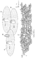
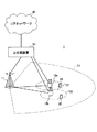
図1は、HetNetの概念図である。図1に示すように、HetNetは、マクロセルM1−M3と地理的に重複するように多数のスモールセルSが配置される無線通信システムである。HetNetは、各マクロセルMを形成する無線基地局(以下、マクロ基地局という)MeNB、各スモールセルSを形成する無線基地局(以下、スモール基地局)SeNB、マクロ基地局MeNB及びスモール基地局SeNBの少なくとも一つと通信するユーザ端末UEとを含む。 FIG. 1 is a conceptual diagram of HetNet. As shown in FIG. 1, HetNet is a radio communication system in which a large number of small cells S are arranged so as to geographically overlap with macro cells M1-M3. The HetNet is a radio base station (hereinafter referred to as a macro base station) MeNB that forms each macro cell M, a radio base station (hereinafter referred to as a small base station) SeNB that forms each small cell S, a macro base station MeNB, and a small base station SeNB. And a user terminal UE that communicates with at least one of the above.
図1に示すように、マクロセルM1−M3では、例えば、800MHzや2GHzなど、相対的に低い周波数帯のキャリア(以下、低周波数帯キャリアという)F1が用いられる。一方、多数のスモールセルSでは、例えば、3.5GHzなど、相対的に高い周波数帯のキャリア(以下、高周波数帯キャリアという)F2が用いられる。尚、800MHzや2GHz、3.5GHzはあくまでも一例である。マクロセルMのキャリアとして、3.5GHzが用いられてもよいし、スモールセルSのキャリアとして、800MHzや2GHz、800MHzや2GHz、1.7GHz等が用いられてもよい。 As shown in FIG. 1, in the macro cells M1-M3, a carrier F1 having a relatively low frequency band (hereinafter referred to as a low frequency band carrier) such as 800 MHz or 2 GHz is used. On the other hand, in many small cells S, for example, a relatively high frequency band carrier (hereinafter, referred to as a high frequency band carrier) F2 such as 3.5 GHz is used. 800 MHz, 2 GHz, and 3.5 GHz are just examples. As a carrier of the macro cell M, 3.5 GHz may be used, and as a carrier of the small cell S, 800 MHz, 2 GHz, 800 MHz, 2 GHz, 1.7 GHz, or the like may be used.
図1に示すHetNetでは、高周波数帯キャリアF2のキャパシティは、セル数が増大することにより、低周波数帯キャリアF1のキャパシティよりも高くなる。このため、伝送速度(スループット)を向上させるためには、ユーザ端末UEは、高周波数帯キャリアF2を用いてスモール基地局SeNBと通信を行うことが好ましい。 In the HetNet shown in FIG. 1, the capacity of the high frequency band carrier F2 becomes higher than the capacity of the low frequency band carrier F1 as the number of cells increases. For this reason, in order to improve a transmission rate (throughput), it is preferable that the user terminal UE communicates with the small base station SeNB using the high frequency band carrier F2.
一方で、高周波数帯キャリアF2の伝搬特性は、低周波数帯キャリアF1の伝搬特性よりも悪い。すなわち、一般的に、高周波数帯キャリアF2は、低周波数帯キャリアF1に比べて、遠くまで伝搬しないという特性を持つ。また、スモールセルS(スモール基地局SeNB)のアンテナは、マクロセルMに比べて、低い位置に打たれる確率が高く、周辺のビルなどの構造物の影響を受けやすく、伝搬特性が悪くなると考えられる。このため、スモールセルS間のカバレッジホールによって、スモールセルS間のハンドオーバの失敗確率が増加したり、スモールセルSの圏外となる確率が増加したりするなど、ネットワーク品質の劣化を招く恐れがある。 On the other hand, the propagation characteristics of the high frequency band carrier F2 are worse than the propagation characteristics of the low frequency band carrier F1. That is, in general, the high frequency band carrier F2 has a characteristic that it does not propagate farther than the low frequency band carrier F1. Further, the antenna of the small cell S (small base station SeNB) has a higher probability of being hit at a lower position than the macro cell M, and is susceptible to the influence of structures such as surrounding buildings, so that the propagation characteristics are deteriorated. It is done. For this reason, the coverage hole between the small cells S may increase the probability of handover failure between the small cells S or increase the probability that the small cells S will be out of the service area. .
このように、図1に示すHetNetにおいて、伝送速度(スループット)の向上のために、高周波数帯キャリアF2だけを用いて通信を行う場合、スモールセルS間のカバレッジホールによりネットワーク品質が劣化する恐れがある。 As described above, in the HetNet shown in FIG. 1, when communication is performed using only the high frequency band carrier F2 in order to improve the transmission rate (throughput), the network quality may be deteriorated due to the coverage hole between the small cells S. There is.
ところで、かかるネットワーク品質の劣化がユーザ体感に与える影響は、上述したように、Webブラウジングやeメールなどのベストエフォート型通信においては、比較的少ないと考えられる。一方で、音声サービス、音声のための発着信などのリアルタイム型通信においては、例えば、電話が切断されてしまう、緊急の電話を受信することができないなど、ユーザ体感に与える影響が大きくなると考えられる。 By the way, it is considered that the influence of the deterioration of the network quality on the user experience is relatively small in the best-effort communication such as Web browsing and e-mail as described above. On the other hand, in real-time communication such as voice service and outgoing and incoming calls for voice, it is considered that the impact on the user experience will be increased, for example, the telephone will be disconnected or the emergency telephone cannot be received. .
そこで、キャリアアグリゲーションのように、マクロセルMとスモールセルSとの双方において同時に通信を行うことで、スモールセルS間のカバレッジホールによるネットワーク品質(特に、音声サービスや発着信などのリアルタイム型通信の品質)の劣化を防止することも検討されている(例えば、文献1:TS36.300, Annex J.1, CA deployment scenario #4, 文献2:H.Ishii et al., “A Novel Architecture for LTE-B, C-plane/U-plane Split and Phantom Cell Concept,” IEEE Globecom 2012 Workshop, 2012)。 Therefore, by performing communication in both the macro cell M and the small cell S at the same time as in carrier aggregation, the network quality due to the coverage hole between the small cells S (particularly the quality of real-time communication such as voice service and outgoing / incoming calls). (For example, reference 1: TS36.300, Annex J.1, CA deployment scenario # 4, reference 2: H.Ishii et al., “A Novel Architecture for LTE- B, C-plane / U-plane Split and Phantom Cell Concept, “IEEE Globecom 2012 Workshop, 2012).
ここで、キャリアアグリゲーション(CA)とは、複数のコンポーネントキャリア(CC)を統合することで広帯域伝送を実現するものである。コンポーネントキャリアは、所定の帯域幅(例えば、20MHz)を有するキャリアであり、上述の低周波数帯キャリアF1や、高周波数帯キャリアF2などであってもよい。以下では、低周波数帯キャリアF1と高周波数帯キャリアF2との2CCを用いたキャリアアグリゲーションを説明する。なお、CAにおいて統合されるCCの数は、2に限られず、3以上(例えば、最大5)であってもよい。 Here, carrier aggregation (CA) realizes broadband transmission by integrating a plurality of component carriers (CC). The component carrier is a carrier having a predetermined bandwidth (for example, 20 MHz), and may be the above-described low frequency band carrier F1, high frequency band carrier F2, or the like. Below, the carrier aggregation using 2CC of the low frequency band carrier F1 and the high frequency band carrier F2 is demonstrated. Note that the number of CCs integrated in CA is not limited to two, and may be three or more (for example, a maximum of five).
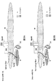
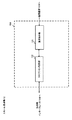
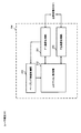
図2は、HetNetにおけるキャリアアグリゲーション(CA)形態の説明図である。HetNetにおけるCA形態としては、基地局内キャリアアグリゲーション(Intra−eNB CA)と、基地局間キャリアアグリゲーション(Inter−eNB CA)とが想定される。 FIG. 2 is an explanatory diagram of a carrier aggregation (CA) mode in HetNet. As CA forms in HetNet, intra-base station carrier aggregation (Intra-eNB CA) and inter-base station carrier aggregation (Inter-eNB CA) are assumed.
基地局内キャリアアグリゲーション(Intra−eNB CA)は、図2Aに示すように、マクロ基地局MeNBだけに通信制御部(例えば、BB(ベースバンド)処理部やスケジューリング部など)が設けられる装置構成、あるいは、ネットワーク構成で行われる。かかる装置構成、あるいは、ネットワーク構成では、マクロ基地局MeNBとスモール基地局SeNBとが光ファイバーで接続される。この場合、スモールセル基地局SeNBは、Remote Radio Headと呼ばれてもよい。また、マクロ基地局MeNBが、マクロセルMにおける低周波数帯キャリアF1を用いた通信とスモールセルSにおける高周波数帯キャリアF2を用いた通信との双方を制御する。 As shown in FIG. 2A, the intra-base station carrier aggregation (Intra-eNB CA) is an apparatus configuration in which only a macro base station MeNB is provided with a communication control unit (for example, a BB (baseband) processing unit or a scheduling unit), or Done in a network configuration. In such an apparatus configuration or network configuration, the macro base station MeNB and the small base station SeNB are connected by an optical fiber. In this case, the small cell base station SeNB may be referred to as a Remote Radio Head. Further, the macro base station MeNB controls both the communication using the low frequency band carrier F1 in the macro cell M and the communication using the high frequency band carrier F2 in the small cell S.
一方、基地局間キャリアアグリゲーション(Inter−eNB CA)は、図2Bに示すように、マクロ基地局MeNBとスモール基地局SeNBとの双方に通信制御部(例えば、BB(ベースバンド)処理部やスケジューリング部など)が設けられる装置構成、あるいは、ネットワーク構成で行われる。かかる装置構成、あるいは、ネットワーク構成では、マクロ基地局MeNBとスモール基地局SeNBとが、光ファイバー以外のリンク(有線又は無線を問わない)で接続されてもよい。また、マクロ基地局MeNBは、マクロセルMにおける低周波数帯キャリアF1を用いた通信を制御し、スモール基地局SeNBは、スモールセルSにおける高周波数帯キャリアF2を用いた通信を制御する。 On the other hand, inter-base station carrier aggregation (Inter-eNB CA), as shown in FIG. 2B, communication control units (for example, a BB (baseband) processing unit and scheduling) for both the macro base station MeNB and the small base station SeNB. For example, a network configuration. In such a device configuration or a network configuration, the macro base station MeNB and the small base station SeNB may be connected by a link other than an optical fiber (whether wired or wireless). The macro base station MeNB controls communication using the low frequency band carrier F1 in the macro cell M, and the small base station SeNB controls communication using the high frequency band carrier F2 in the small cell S.
図2Aの基地局内キャリアアグリゲーションや図2Bの基地局間キャリアアグリゲーションにおいては、マクロセルMとスモールセルSとの双方において同時に通信が行なわれる。このため、スモールセルS間のカバレッジホール(図1参照)をマクロセルMのカバレッジでカバーでき、スモールセルS間のカバレッジホールによるネットワーク品質の劣化を防止できる。より具体的には、音声サービスを常にマクロセルMから提供するという形で通信を行う場合、スモールセル間のカバレッジホールは、音声サービスに悪影響を与えないことになる。 In the intra-base station carrier aggregation of FIG. 2A and the inter-base station carrier aggregation of FIG. 2B, both the macro cell M and the small cell S communicate simultaneously. For this reason, the coverage hole (refer FIG. 1) between the small cells S can be covered with the coverage of the macrocell M, and the deterioration of the network quality by the coverage hole between the small cells S can be prevented. More specifically, when communication is performed in such a manner that the voice service is always provided from the macro cell M, the coverage hole between the small cells does not adversely affect the voice service.
しかしながら、図2Aの基地局内キャリアアグリゲーションでは、マクロ基地局MeNBとスモール基地局SeNBとを高コストの光ファイバーで接続する必要がある。このため、基地局内キャリアアグリゲーションは、コストの観点から好ましくない場合がある。 However, in the intra-base station carrier aggregation of FIG. 2A, it is necessary to connect the macro base station MeNB and the small base station SeNB with a high-cost optical fiber. For this reason, carrier aggregation in the base station may not be preferable from the viewpoint of cost.
また、図2Bの基地局間キャリアアグリゲーションでは、マクロ基地局MeNB及びスモール基地局SeNBがそれぞれ、Uプレーン(ユーザデータ)の通信制御を行う。この場合、Uプレーンの終端の仕方によっては、基地局間キャリアアグリゲーションを行うシステムが複雑化し、結果として、高コストとなる恐れがある。 Moreover, in the carrier aggregation between base stations of FIG. 2B, macro base station MeNB and small base station SeNB each perform communication control of U plane (user data). In this case, depending on how the U plane is terminated, a system for performing carrier aggregation between base stations becomes complicated, and as a result, there is a risk of high costs.
また、図2Aの基地局内キャリアアグリゲーション、及び、図2Bの基地局間キャリアアグリゲーションでは、ユーザ端末UEがマクロ基地局MeNBとスモール基地局SeNBとの双方と信号を送受信する必要があるため、ユーザ端末UEの消費電力が増大する恐れもある。 Further, in the intra-base station carrier aggregation of FIG. 2A and the inter-base station carrier aggregation of FIG. 2B, the user terminal UE needs to transmit and receive signals to both the macro base station MeNB and the small base station SeNB. There is also a risk that the power consumption of the UE increases.
そこで、本発明者らは、キャリアアグリゲーションを行わずに、或いは、当該キャリアアグリゲーションを行う場合であってもユーザ端末UEにおける消費電力を軽減しながら、スモールセルS間のカバレッジホールによるネットワーク品質(特に、音声サービスや発着信などのリアルタイム型通信のサービス品質)の劣化を防止可能な無線通信方法を検討し、本発明に至った。 Therefore, the present inventors do not perform carrier aggregation, or reduce the power consumption in the user terminal UE even when the carrier aggregation is performed, while reducing the network quality due to the coverage hole between the small cells S (particularly, The present inventors have studied a wireless communication method capable of preventing deterioration of service quality of real-time communication such as voice service and incoming / outgoing calls and arrived at the present invention.
本発明に係る無線通信方法では、ユーザ端末UEは、マクロセルM(第1セル)を形成するマクロ基地局MeNB(第1無線基地局)とスモールセルS(第2セル)を形成するスモール基地局SeNB(第2無線基地局)との少なくとも一つと通信を行う。また、ユーザ端末UEは、第2キャリアにおいてスモール基地局SeNBと通信を行っている場合に、第1キャリアにおいてマクロ基地局MeNBからページング信号を受信する。 In the radio communication method according to the present invention, the user terminal UE forms a macro base station MeNB (first radio base station) that forms a macro cell M (first cell) and a small base station that forms a small cell S (second cell). It communicates with at least one with SeNB (2nd radio base station). In addition, when the user terminal UE is communicating with the small base station SeNB in the second carrier, the user terminal UE receives a paging signal from the macro base station MeNB in the first carrier.
ここで、第1キャリアとは、マクロセルMにおいてマクロ基地局MeNB(第1無線基地局)との通信に用いられる所定周波数帯のキャリアであり、例えば、低周波数帯キャリアF1であってもよい。また、第2キャリアとは、スモールセルSにおいてスモール基地局SeNB(第2無線基地局)との通信に用いられる所定周波数帯のキャリアであり、例えば、高周波数帯キャリアF2であってもよい。 Here, the first carrier is a carrier in a predetermined frequency band used for communication with the macro base station MeNB (first radio base station) in the macro cell M, and may be, for example, the low frequency band carrier F1. Further, the second carrier is a carrier in a predetermined frequency band used for communication with the small base station SeNB (second radio base station) in the small cell S, and may be, for example, the high frequency band carrier F2.
また、「第1キャリアにおいてページング信号を受信する」とは、「第1キャリアにおいて、アイドル(Idle)状態と同等のメジャメント処理(測定処理)を行い、ページング信号を受信する」という意味であってもよい。以下に、アイドル状態におけるページング信号の受信処理、及び、メジャメント処理を詳細に説明する。 “Receiving the paging signal in the first carrier” means “performing measurement processing (measurement processing) equivalent to the idle state in the first carrier and receiving the paging signal”. Also good. The paging signal reception process and measurement process in the idle state will be described in detail below.
ユーザ端末UEは、アイドル状態においては、消費電力を抑制するため、所定周期(例えば、Paging cycleというパラメータで定義される周期)に基づき、ページング信号のモニターを行う。Paging cycleは、TS 36.331では、例えば、defaultPagingCycleとして定義されている。また、Paging cycleの値は、例えば、1.28 secや2.56 secである。また、ページング信号のモニターとは、自端末宛にページング信号が送信されるか否かを検出(監視)する処理のことを指す。すなわち、ユーザ端末UEは、Paging cycle毎に、自端末宛にページング信号が送信されるか否かを検出しようとする。 In the idle state, the user terminal UE monitors the paging signal based on a predetermined cycle (for example, a cycle defined by a parameter called Paging cycle) in order to suppress power consumption. Paging cycle is defined as defaultPagingCycle in TS 36.331, for example. The value of Paging cycle is, for example, 1.28 sec or 2.56 sec. The monitoring of the paging signal refers to a process of detecting (monitoring) whether or not a paging signal is transmitted to the terminal itself. That is, the user terminal UE tries to detect whether or not a paging signal is transmitted to the user terminal every Paging cycle.
この場合、ユーザ端末UEは、ページング信号をモニターする必要のある時間においてのみ、自端末宛にページング信号が送信されるか否かを検出する処理を行う。すなわち、ユーザ端末UEは、ページング信号をモニターする必要のない時間においては、スリープ状態または省電力状態となり、消費電力を大幅に低減することが可能となる。このようなユーザ端末UEの動作は、DRX(Discontinuous Reception)と呼ばれてもよい。尚、アイドル状態におけるDRXの処理は、Paging DRXと呼ばれてもよい。また、後述する監視期間とは、かかる「ページング信号をモニターする必要のある時間」に相当する。 In this case, the user terminal UE performs a process of detecting whether or not the paging signal is transmitted to the user terminal only during the time when the paging signal needs to be monitored. That is, the user terminal UE is in a sleep state or a power saving state during a time when it is not necessary to monitor the paging signal, and can greatly reduce power consumption. Such an operation of the user terminal UE may be referred to as DRX (Discontinuous Reception). Note that the DRX process in the idle state may be referred to as Paging DRX. Further, a monitoring period described later corresponds to such “time when paging signal needs to be monitored”.
一方、アイドル状態であるか、コネクテッド状態であるかに関わらず、ユーザ端末UEは移動を行っており、ユーザ端末UEは、アイドル状態においても、サービングセル、及び、周辺セルの無線品質のメジャメントを行い、最も無線品質の良いセルがサービングセルから、周辺セルに変化した場合、ユーザ端末UEは、かかる最も無線品質の良い周辺セルをサービングセルとする。このようなアイドル状態におけるサービングセルの切り替えはCell reselectionと呼ばれる。ここで、無線品質とは、例えば、Reference Signal Received Power (RSRP)、または、Reference Signal Received Quality (RSRQ)であってもよい。尚、アイドル状態におけるかかるサービングセルは、ユーザ端末UEが在圏しているセルと呼ばれてもよい。尚、一般に、ユーザ端末UEは、ページング信号をモニターするタイミング、あるいは、そのタイミングの前後で(後述する監視期間であってもよい)、上述のサービングセル、及び、周辺セルのメジャメントを行うことにより、スリープ状態である時間を最大化し、消費電力の低減を図っている。Cell reselectionに関しては、例えば、TS 36.304、5.2章にその動作が規定されている。あるいは、Cell reselectionの要求条件は、例えば、TS 36.133、4.2章に規定されている。 On the other hand, the user terminal UE is moving regardless of whether it is in an idle state or a connected state, and the user terminal UE measures the radio quality of the serving cell and neighboring cells even in the idle state. When the cell with the best radio quality changes from the serving cell to the neighboring cell, the user terminal UE sets the neighboring cell with the best radio quality as the serving cell. Switching of the serving cell in such an idle state is called cell reselection. Here, the radio quality may be, for example, Reference Signal Received Power (RSRP) or Reference Signal Received Quality (RSRQ). Note that such a serving cell in the idle state may be referred to as a cell where the user terminal UE is located. In general, the user terminal UE performs the above-described serving cell and neighboring cell measurement at the timing of monitoring the paging signal, or before and after the timing (may be a monitoring period to be described later). The time in the sleep state is maximized to reduce power consumption. The operation of Cell reselection is specified in TS 36.304, Chapter 5.2, for example. Alternatively, the requirements for Cell reselection are defined in, for example, TS 36.133, Chapter 4.2.
ここで、ユーザ端末UEが適切にサービングセル、あるいは、周辺セルのメジャメントを行わない場合、すなわち、Cell reselectionが適切に行われない場合、最も無線品質の良いセルに在圏することができず、結果として、ページング信号の受信に失敗することになる。よって、上述の「第1キャリアにおいてページング信号を受信する」とは、「第1キャリアにおいて、アイドル状態と同等のメジャメント処理を行い、ページング信号を受信する」、あるいは、「第1キャリアにおいて、アイドル状態と同等のCell reselectionを行い、ページング信号を受信する」と同義となる。 Here, when the user terminal UE does not appropriately measure the serving cell or the neighboring cell, that is, when the cell reselection is not properly performed, the user terminal UE cannot reach the cell with the best radio quality. As a result, the paging signal reception fails. Therefore, the above-mentioned “receive a paging signal in the first carrier” means “perform measurement processing equivalent to the idle state in the first carrier and receive the paging signal”, or “receive the idle signal in the first carrier. This is synonymous with “re-selecting the cell and selecting the state and receiving the paging signal”.
例えば、ユーザ端末UEが、第2キャリアにおいてスモール基地局SeNBと通信を行っている状態で、音声呼の着信が発生した場合、従来の方法では、スモール基地局SeNBが、すでに確立されているコネクションを用いて、ユーザ端末UEに対して、かかる音声呼の着信が発生したことを通知する。この場合、例えば、個別のRRC制御信号が用いられる。この場合、ユーザ端末UEとスモール基地局SeNBのコネクションの無線品質が良い場合には問題ないが、上述したように、第2キャリアにおいてはスモールセルS間のカバレッジホールの確率が高く、ユーザ端末UEが、たまたまかかるカバレッジホールに位置した場合には、音声呼の着信処理が正常に行われない、という事象が発生する。すなわち、第2キャリアにおけるカバレッジホールの頻度が、第1キャリアにおけるカバレッジホールの頻度よりも大きい場合、音声呼の着信という観点でのサービス品質は劣化することになる。 For example, when an incoming voice call occurs while the user terminal UE is communicating with the small base station SeNB in the second carrier, in the conventional method, the small base station SeNB has already been established. Is used to notify the user terminal UE that an incoming voice call has occurred. In this case, for example, an individual RRC control signal is used. In this case, there is no problem when the radio quality of the connection between the user terminal UE and the small base station SeNB is good, but as described above, in the second carrier, the probability of a coverage hole between the small cells S is high, and the user terminal UE However, when it happens to be located in such a coverage hole, an event that the incoming processing of the voice call is not normally performed occurs. That is, when the frequency of coverage holes in the second carrier is greater than the frequency of coverage holes in the first carrier, the service quality in terms of incoming voice calls will deteriorate.
あるいは、ユーザ端末UEとスモール基地局SeNBのコネクションの無線品質が良く、かかる音声呼の着信が正常に行われた場合にも、第2キャリアではカバレッジホールの頻度が高いため、ユーザ端末UEが、スモール基地局SeNB間のハンドオーバを行う際に、かかる音声呼が切断される可能性が高い。 Alternatively, the radio quality of the connection between the user terminal UE and the small base station SeNB is good, and even when such a voice call is normally received, since the frequency of coverage holes is high in the second carrier, the user terminal UE When performing handover between the small base stations SeNB, there is a high possibility that the voice call is disconnected.
また、ユーザ端末UEが、スモール基地局SeNBからマクロ基地局MeNBに異周波のハンドオーバ(Inter-frequency Handover)を行う際にも、第2キャリアの伝搬特性を考慮すると、第2キャリアでのスモール基地局SeNBとユーザ端末UEとの無線品質が急激に劣化する可能性があるため、結果として、音声呼が切断される可能性が高い。 In addition, when the user terminal UE performs a different frequency handover (Inter-frequency Handover) from the small base station SeNB to the macro base station MeNB, the small base on the second carrier is considered in consideration of the propagation characteristics of the second carrier. Since the radio quality between the station SeNB and the user terminal UE may be rapidly deteriorated, the voice call is likely to be disconnected as a result.
よって、ユーザ端末UEが第2キャリアにおいてスモール基地局SeNBと通信を行っている場合に、第1キャリアにおいてマクロ基地局MeNBからページング信号を受信することにより、スモールセルS間のカバレッジホールによるネットワーク品質(特に、音声サービスや着信(ページング)などのリアルタイム型通信の品質)の劣化を防止できる。 Therefore, when the user terminal UE is communicating with the small base station SeNB in the second carrier, the network quality due to the coverage hole between the small cells S by receiving the paging signal from the macro base station MeNB in the first carrier. (In particular, the quality of real-time communication such as voice service and incoming call (paging)) can be prevented.
また、音声呼が発生した場合には、ユーザ端末UEは、基本的には、第1キャリアにおいてマクロ基地局MeNBと通信を行うため、ハンドオーバによる音声呼の切断も回避することが可能となる。 In addition, when a voice call occurs, the user terminal UE basically communicates with the macro base station MeNB on the first carrier, so that it is possible to avoid disconnection of the voice call due to handover.
以上のように、本発明に係る無線通信方法では、ユーザ端末UEは、第2キャリアにおいてスモール基地局SeNBと通信を行っている場合に、第1キャリアにおいて音声呼の発着信処理(上述のページング信号の受信、音声呼の発信処理を含む)を行う。このため、本発明に係る無線通信方法では、スモールセルS間のカバレッジホールによるリアルタイム型通信のサービス品質(例えば、音声サービスや発着信のサービス品質)の劣化を防止できる。 As described above, in the wireless communication method according to the present invention, when the user terminal UE is communicating with the small base station SeNB in the second carrier, the voice call transmission / reception processing (the above-described paging is performed in the first carrier). Signal reception and voice call origination processing). For this reason, in the radio communication method according to the present invention, it is possible to prevent deterioration of service quality (for example, voice service or service quality of outgoing / incoming calls) of real-time communication due to a coverage hole between the small cells S.
(無線通信方法)
以下、図3−図5を参照し、本発明の第1−第3態様に係る無線通信方法を詳細に説明する。以下では、第1キャリアとして低周波数帯キャリアF1が用いられ、第2キャリアとして高周波数帯キャリアF2が用いられる場合を説明するが、これに限られない。本発明に係る無線通信方法は、第1キャリア及び第2キャリアで同一の周波数帯のキャリアなどが用いられる場合にも適用可能である。
(Wireless communication method)
Hereinafter, the wireless communication method according to the first to third aspects of the present invention will be described in detail with reference to FIGS. Below, although the case where the low frequency band carrier F1 is used as a 1st carrier and the high frequency band carrier F2 is used as a 2nd carrier is demonstrated, it is not restricted to this. The radio communication method according to the present invention is also applicable to cases where the first carrier and the second carrier use the same frequency band.
また、以下では、基地局間キャリアアグリゲーションが行なわれる構成(図2B)を想定するが、これに限られない。本発明に係る無線通信方法は、基地局内キャリアアグリゲーションが行なわれる構成(図2A)においても適用可能である。 Moreover, although the structure (FIG. 2B) in which the carrier aggregation between base stations is performed is assumed below, it is not restricted to this. The radio communication method according to the present invention can also be applied to a configuration (FIG. 2A) in which intra-base station carrier aggregation is performed.
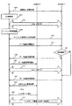
図3Aは、本発明の第1態様に係る無線通信方法の説明図である。第1態様に係る無線通信方法では、ユーザ端末UEが高周波数帯キャリアF2においてスモール基地局SeNBと通信を行っている場合に、第1キャリアにおいて音声呼を着信する動作について説明する。 FIG. 3A is an explanatory diagram of the radio communication method according to the first aspect of the present invention. In the radio communication method according to the first aspect, an operation of receiving a voice call in the first carrier when the user terminal UE is communicating with the small base station SeNB in the high frequency band carrier F2 will be described.
図3Aに示すように、ユーザ端末UEは、マクロ基地局MeNBに対する初期セル接続処理を行う(ステップS101)。具体的には、ユーザ端末UEは、セルサーチによりマクロセルMを検出し、マクロ基地局MeNBに対するランダムアクセス処理、マクロ基地局MeNBとのコネクション(例えば、RRCコネクションなど)の確立処理などを行う。 As illustrated in FIG. 3A, the user terminal UE performs an initial cell connection process for the macro base station MeNB (step S101). Specifically, the user terminal UE detects the macro cell M by cell search, and performs a random access process for the macro base station MeNB, a process for establishing a connection (for example, an RRC connection) with the macro base station MeNB, and the like.
なお、ステップS101における初期セル接続処理において、ユーザ端末UEは、マクロ基地局MeNBに対して、CA能力通知情報を送信してもよい。ここで、CA能力通知情報とは、ユーザ端末UEがキャリアアグリゲーション(CA)を行う能力を有するか否かを通知する情報である。CA能力通知情報としては、例えば、「UE Capability」などが用いられてもよい。 In the initial cell connection process in step S101, the user terminal UE may transmit CA capability notification information to the macro base station MeNB. Here, the CA capability notification information is information for notifying whether or not the user terminal UE has the capability to perform carrier aggregation (CA). As the CA capability notification information, for example, “UE Capability” may be used.
ユーザ端末UEは、セルサーチにより高周波数帯キャリアF2においてスモールセルSを検出する(ステップS102)。例えば、ユーザ端末UEは、スモール基地局SeNBから送信されている同期信号や参照信号に基づいて、スモールセルSを検出してもよい。あるいは、ユーザ端末UEは、スモール基地局SeNBから送信されている、かかる同期信号や参照信号以外の信号(例えば、ディスカバリー信号など)に基づいて、スモールセルSを検出してもよい。 The user terminal UE detects the small cell S in the high frequency band carrier F2 by cell search (step S102). For example, the user terminal UE may detect the small cell S based on a synchronization signal or a reference signal transmitted from the small base station SeNB. Alternatively, the user terminal UE may detect the small cell S based on a signal (for example, a discovery signal) other than the synchronization signal and the reference signal transmitted from the small base station SeNB.
ユーザ端末UEは、ステップS102でスモールセルSを検出すると、マクロ基地局MeNBからスモール基地局SeNBに対するハンドオーバ処理を行う(ステップS103)。具体的には、ユーザ端末UEは、スモール基地局SeNBとのコネクション(例えば、RRCコネクションなど)の確立処理を行う。一方、ユーザ端末UEは、ステップS101で確立されたマクロ基地局MeNBとのコネクションの解放処理を行う。 When detecting the small cell S in step S102, the user terminal UE performs a handover process from the macro base station MeNB to the small base station SeNB (step S103). Specifically, the user terminal UE performs a process of establishing a connection (for example, an RRC connection) with the small base station SeNB. On the other hand, the user terminal UE performs a connection release process with the macro base station MeNB established in step S101.
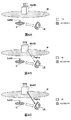
ステップS103でのハンドオーバ処理が完了すると、図4Aに示すように、ユーザ端末UEは、高周波数帯キャリアF2を用いて、スモール基地局SeNBとの通信を行う。高周波数帯キャリアF2のキャパシティは、一般に、マクロセルMで用いられる低周波数帯キャリアF1のキャパシティよりも高い。このため、高周波数帯キャリアF2を用いてスモール基地局SeNBと通信を行うことにより、データスループットが向上する。 When the handover process in step S103 is completed, as shown in FIG. 4A, the user terminal UE communicates with the small base station SeNB using the high frequency band carrier F2. The capacity of the high frequency band carrier F2 is generally higher than the capacity of the low frequency band carrier F1 used in the macro cell M. For this reason, data throughput improves by communicating with the small base station SeNB using the high frequency band carrier F2.
また、図4Bに示すように、ユーザ端末UEは、高周波数帯キャリアF2を用いてスモール基地局SeNBと通信を行っている場合、所定周期の監視期間で、マクロ基地局MeNBからページング信号が送信されるか否かを監視(monitor)する(ステップS104)。ここで、かかるページング信号が送信されるか否かを監視する処理は、上述したように、アイドル状態におけるページング信号の受信処理と同一、あるいは、同等であってもよい。また、かかるページング信号が送信されるか否かを監視する処理には、サービングセル、または、周辺セルの無線品質を測定するメジャメント処理、及び、サービングセルを切り替えるCell reselection処理が含まれてもよい。 Moreover, as shown in FIG. 4B, when the user terminal UE is communicating with the small base station SeNB using the high frequency band carrier F2, a paging signal is transmitted from the macro base station MeNB in a monitoring period of a predetermined period. It is monitored (monitored) whether it is performed (step S104). Here, the process for monitoring whether or not such a paging signal is transmitted may be the same as or equivalent to the paging signal reception process in the idle state, as described above. The process for monitoring whether or not such a paging signal is transmitted may include a measurement process for measuring the radio quality of the serving cell or neighboring cells, and a Cell reselection process for switching the serving cell.
具体的には、ユーザ端末UEは、上記監視期間においてマクロ基地局MeNBからページング通知情報が受信されるか否かを監視してもよい。ここで、ページング通知情報とは、マクロ基地局MeNBからページング信号が送信されることを通知する情報であり、例えば、P−RNTI(Paging Radio Network Temporary ID)が使用される下り制御チャネルなどが用いられる。かかる下り制御チャネルは、例えば、下り制御チャネル(PDCCH:Physical Downlink Control Channel)、拡張下り制御チャネル(EPDCCH:Enhanced PDCCH)を用いて送信される。 Specifically, the user terminal UE may monitor whether or not the paging notification information is received from the macro base station MeNB during the monitoring period. Here, the paging notification information is information for notifying that a paging signal is transmitted from the macro base station MeNB, and for example, a downlink control channel using a P-RNTI (Paging Radio Network Temporary ID) is used. It is done. The downlink control channel is transmitted using, for example, a downlink control channel (PDCCH: Physical Downlink Control Channel) and an enhanced downlink control channel (EPDCCH: Enhanced PDCCH).
なお、上記監視期間において、ユーザ端末UEは、高周波数帯キャリアF2を用いたスモール基地局SeNBとの通信を停止してもよい。具体的には、スモール基地局SeNBは、マクロ基地局MeNBから送信されるページング信号に関するユーザ端末UEの監視期間においてユーザ端末UEに対するPDSCH又は上り共有データチャネル(PUSCH:Physical Uplink Shared Channel)の割り当てを停止してもよい。 In the monitoring period, the user terminal UE may stop communication with the small base station SeNB using the high frequency band carrier F2. Specifically, the small base station SeNB allocates PDSCH or uplink shared data channel (PUSCH: Physical Uplink Shared Channel) to the user terminal UE in the monitoring period of the user terminal UE regarding the paging signal transmitted from the macro base station MeNB. You may stop.
ここで、かかる監視期間は、マクロ基地局MeNBからスモール基地局SeNBに事前に通知されてもよい。例えば、S103におけるハンドオーバ処理において、一般に、マクロ基地局MeNBとスモール基地局SeNBは、互いに制御信号のやり取りを行う。かかる制御信号に、前記監視期間が通知されてもよい。あるいは、かかる監視期間は、ユーザ端末UEから、スモール基地局SeNBに通知されてもよい。この場合、ユーザ端末UEは、第1キャリアにおけるサービングセルが切り替わる度に、スモール基地局SeNBに対して、かかる監視期間を通知してもよい。 Here, the monitoring period may be notified in advance from the macro base station MeNB to the small base station SeNB. For example, in the handover process in S103, generally, the macro base station MeNB and the small base station SeNB exchange control signals with each other. The monitoring period may be notified to the control signal. Alternatively, the monitoring period may be notified from the user terminal UE to the small base station SeNB. In this case, the user terminal UE may notify the small base station SeNB of the monitoring period every time the serving cell in the first carrier is switched.
あるいは、ユーザ端末UEは、自律的に、上記監視期間において、高周波数帯キャリアF2を用いたスモール基地局SeNBとの通信を停止してもよい。この場合、かかる監視期間において、スモール基地局SeNBが高周波数帯キャリアF2を用いてユーザ端末UEに送信した信号は破棄される。あるいは、かかる監視期間において、ユーザ端末UEは、高周波数帯キャリアF2を用いて信号を送信しない。 Alternatively, the user terminal UE may autonomously stop communication with the small base station SeNB using the high frequency band carrier F2 during the monitoring period. In this case, during the monitoring period, the signal transmitted from the small base station SeNB to the user terminal UE using the high frequency band carrier F2 is discarded. Or in this monitoring period, user terminal UE does not transmit a signal using high frequency band carrier F2.
また、図4Cに示すように、ユーザ端末UEは、監視期間においてマクロ基地局MeNBからページング通知情報を受信した場合、当該ページング通知情報に基づいてマクロ基地局MeNBからページング信号を受信する(ステップS105)。当該ページング信号に自端末の識別子が含まれる場合、ユーザ端末UEは、マクロ基地局MeNBからの自端末の呼び出し(ページング)を検出する。 Moreover, as shown in FIG. 4C, when receiving the paging notification information from the macro base station MeNB during the monitoring period, the user terminal UE receives a paging signal from the macro base station MeNB based on the paging notification information (step S105). ). When the identifier of the own terminal is included in the paging signal, the user terminal UE detects a call (paging) of the own terminal from the macro base station MeNB.
なお、マクロ基地局MeNBからのページング信号は、例えば、上記ページング通知情報である、P−RNTIを用いたPDCCH/EPDCCH(あるいは、そのPDCCH/EPDCCHにマッピングされる下り制御情報(DCI))が示す下り共有データチャネル(PDSCH:Physical Downlink Shared Channel)を介して送信されてもよい。 Note that the paging signal from the macro base station MeNB indicates, for example, PDCCH / EPDCCH using P-RNTI (or downlink control information (DCI) mapped to the PDCCH / EPDCCH) that is the paging notification information. It may be transmitted via a downlink shared data channel (PDSCH: Physical Downlink Shared Channel).
ユーザ端末UEは、マクロ基地局MeNBからの自端末の呼び出し(ページング)を検出すると、マクロ基地局MeNBに対して、コネクション(例えば、RRCコネクションなど)の確立要求を送信する(ステップS106)。より具体的には、例えば、ユーザ端末UEは、ランダムアクセスプロシージャーを用いてRRC connection requestをマクロ基地局MeNBに対して送信することにより、かかるコネクション確立要求を送信してもよい。 When the user terminal UE detects a call (paging) of the terminal from the macro base station MeNB, the user terminal UE transmits a connection establishment request (for example, an RRC connection) to the macro base station MeNB (step S106). More specifically, for example, the user terminal UE may transmit the connection establishment request by transmitting an RRC connection request to the macro base station MeNB using a random access procedure.
マクロ基地局MeNBは、ユーザ端末UEからのコネクションの確立要求を受信すると、ステップS101におけるCA能力通知情報に基づいて、ユーザ端末UEがキャリアアグリゲーションを行う能力(以下、CA能力という)を有するか否かを判定する(ステップS107)。 When receiving the connection establishment request from the user terminal UE, the macro base station MeNB determines whether or not the user terminal UE has a capability of performing carrier aggregation (hereinafter referred to as CA capability) based on the CA capability notification information in step S101. Is determined (step S107).
ユーザ端末UEがCA能力を有する場合(ステップS107;Yes)、マクロ基地局MeNBとユーザ端末UEとの間のコネクションの確立処理が行なわれる(ステップS108)。ユーザ端末UEは、マクロ基地局MeNBとのコネクションの確立処理が完了すると、スモール基地局SeNBに対してコネクション確立通知を送信する(ステップS109)。ここで、コネクション確立通知とは、マクロ基地局MeNBとのコネクションが確立されたことを通知する通知情報である。 When the user terminal UE has CA capability (step S107; Yes), a process for establishing a connection between the macro base station MeNB and the user terminal UE is performed (step S108). When the establishment process of the connection with the macro base station MeNB is completed, the user terminal UE transmits a connection establishment notification to the small base station SeNB (step S109). Here, the connection establishment notification is notification information for notifying that a connection with the macro base station MeNB has been established.
コネクション確立通知に応じて、図5Aに示すように、基地局間キャリアアグリゲーションによって、低周波数帯キャリアF1及び高周波数帯キャリアF2の双方を用いた通信が行なわれる(ステップS110)。 In response to the connection establishment notification, as shown in FIG. 5A, communication using both the low frequency band carrier F1 and the high frequency band carrier F2 is performed by inter-base station carrier aggregation (step S110).
尚、ステップS109の前、あるいは、後で、マクロ基地局MeNBとスモール基地局SeNBは、互いに制御信号をやり取りし、基地局間キャリアアグリゲーションを用いた通信を確立するための制御処理を行うように構成されていてもよい。尚、上記に示すような、マクロ基地局MeNBとスモール基地局SeNBの間の制御信号のやり取りが行われる場合には、ステップS109はスキップされてもよい。 In addition, before or after step S109, the macro base station MeNB and the small base station SeNB exchange control signals with each other, and perform control processing for establishing communication using inter-base station carrier aggregation. It may be configured. Note that, when the control signal is exchanged between the macro base station MeNB and the small base station SeNB as described above, step S109 may be skipped.
一方、ユーザ端末UEがCA能力を有しない場合(ステップS107;No)、マクロ基地局MeNBとユーザ端末UEとの間のコネクションの確立処理が行なわれる(ステップS111)。当該確立処理が完了すると、図5Bに示すように、スモール基地局SeNBとユーザ端末UEとの間のコネクションの解放処理が行なわれる(ステップS112)。これにより、低周波数帯キャリアF1だけを用いた通信が行なわれる。 On the other hand, when the user terminal UE does not have the CA capability (step S107; No), a process for establishing a connection between the macro base station MeNB and the user terminal UE is performed (step S111). When the establishment process is completed, a connection release process between the small base station SeNB and the user terminal UE is performed as illustrated in FIG. 5B (step S112). Thereby, communication using only the low frequency band carrier F1 is performed.
或いは、ユーザ端末UEがCA能力を有しない場合(ステップS107:No)、図5Cに示すように、スモール基地局SeNBは、ユーザ端末UEに対して、スモール基地局SeNBからマクロ基地局MeNBへのハンドオーバ指示を送信してもよい(ステップS113)。ここで、ハンドオーバ指示は、スモール基地局SeNBとのコネクションをマクロ基地局MeNBとのコネクションに引継ぐ(ハンドオーバする)ことを指示する指示情報である。かかるハンドオーバ指示は、マクロ基地局MeNBからの指示に基づいて行われてもよい。当該ハンドオーバ指示に応じて、ユーザ端末UEは、スモール基地局SeNBからマクロ基地局MeNBへのハンドオーバ処理を行う(ステップS114)。 Alternatively, when the user terminal UE does not have the CA capability (step S107: No), as illustrated in FIG. 5C, the small base station SeNB sends the user terminal UE from the small base station SeNB to the macro base station MeNB. A handover instruction may be transmitted (step S113). Here, the handover instruction is instruction information for instructing to take over (hand over) the connection with the small base station SeNB to the connection with the macro base station MeNB. Such a handover instruction may be performed based on an instruction from the macro base station MeNB. In response to the handover instruction, the user terminal UE performs a handover process from the small base station SeNB to the macro base station MeNB (step S114).
尚、上述した例においては、ステップS107において、ユーザ端末UEがCA能力を有するか否かに基づいて、ステップS109、S110に進むか、ステップS111、S112、または、ステップS113、S114に進むかが判定されたが、本発明に係る別の実施形態においては、基地局間キャリアアグリゲーション(Inter-eNB CA)は行わないという運用方針のもと、ステップS107が省略され、常に、ステップS111、S112、または、ステップS113、S114に進むように処理が行われてもよい。 In the above-described example, whether or not the process proceeds to steps S109 and S110, or proceeds to steps S111 and S112, or steps S113 and S114 based on whether or not the user terminal UE has the CA capability in step S107. Although determined, in another embodiment according to the present invention, step S107 is omitted under the operation policy that inter-base station carrier aggregation (Inter-eNB CA) is not performed, and steps S111, S112, Alternatively, processing may be performed so as to proceed to steps S113 and S114.
以上の本発明の第1態様に係る無線通信方法によれば、ユーザ端末UEは、高周波数帯キャリアF2を用いてスモール基地局SeNBと通信を行っている場合であっても、低周波数帯キャリアF1を用いてマクロ基地局MeNBからページング信号を受信する。このため、スモールセルS間のカバレッジホールによる音声サービスの着信失敗を防止することができ、ネットワーク品質(特に、音声サービスや音声サービスの着信などのリアルタイム型通信のサービス品質)の劣化を防止できる。 According to the above radio communication method according to the first aspect of the present invention, the user terminal UE is a low frequency band carrier even when the user terminal UE is communicating with the small base station SeNB using the high frequency band carrier F2. A paging signal is received from the macro base station MeNB using F1. For this reason, it is possible to prevent an incoming failure of a voice service due to a coverage hole between the small cells S, and it is possible to prevent deterioration of network quality (particularly, service quality of real-time communication such as an incoming voice service or an incoming voice service).
尚、上述のページング信号は、音声の着信のためのページング信号ではなく、システムインフォメーションの変更を通知するページング信号や、ETWSのPrimary notificationやSecondary notificationを通知するページング信号、CMASのnotificationを通知するページング信号であってもよい。 Note that the above paging signal is not a paging signal for incoming voice, but a paging signal for notifying system information changes, a paging signal for notifying ETWS primary notification and secondary notification, and a paging for notifying CMAS notification. It may be a signal.
図3Bは、本発明の第2態様に係る無線通信方法の説明図である。第2態様に係る無線通信方法では、ユーザ端末UEが高周波数帯キャリアF2においてスモール基地局SeNBと通信を行っている場合に、第1キャリアにおいて音声呼を発信する動作について説明する。 FIG. 3B is an explanatory diagram of the radio communication method according to the second aspect of the present invention. In the radio communication method according to the second aspect, an operation of transmitting a voice call in the first carrier when the user terminal UE is communicating with the small base station SeNB in the high frequency band carrier F2 will be described.
以下では、図3Aと同等、あるいは、同一の処理に関しては、説明を省略し、図3Aと異なる部分を主に説明する。図3BのステップS201、S202、S203は、それぞれ、図3AのステップS101、ステップS102、ステップS103と同一であるため、説明を省略する。 In the following, description of processes that are the same as or the same as those in FIG. 3A will be omitted, and portions different from FIG. 3A will be mainly described. Steps S201, S202, and S203 in FIG. 3B are the same as steps S101, S102, and S103 in FIG.
ステップS204において、ユーザ端末UEは、高周波数帯キャリアF2を用いてスモール基地局SeNBと通信を行っている場合、所定周期の監視期間で、マクロ基地局MeNBからページング信号が送信されるか否かを監視(monitor)する。ここで、かかるページング信号が送信されるか否かを監視する処理は、上述したように、アイドル状態におけるページング信号の受信処理と同一、あるいは、同等であってもよい。また、かかるページング信号が送信されるか否かを監視する処理には、サービングセル、または、周辺セルの無線品質を測定するメジャメント処理、及び、サービングセルを切り替えるCell reselection処理が含まれてもよい。かかる監視に関する処理に関しては、上述と同一であるため、その詳細の説明は省略する。 In step S204, when the user terminal UE is communicating with the small base station SeNB using the high frequency band carrier F2, whether or not a paging signal is transmitted from the macro base station MeNB in a monitoring period of a predetermined period. To monitor. Here, the process for monitoring whether or not such a paging signal is transmitted may be the same as or equivalent to the paging signal reception process in the idle state, as described above. The process for monitoring whether or not such a paging signal is transmitted may include a measurement process for measuring the radio quality of the serving cell or neighboring cells, and a Cell reselection process for switching the serving cell. Since the processing related to such monitoring is the same as described above, detailed description thereof is omitted.
ステップS205において、ユーザ端末UEから音声サービスの発信処理がトリガーされる。より具体的には、例えば、ユーザが音声サービスの発信ボタンを押すことにより(ユーザ端末UEがユーザからの音声サービスの発信要求を受け付けることにより)、かかる発信処理がトリガーされてもよい。 In step S205, the voice service transmission process is triggered from the user terminal UE. More specifically, for example, when the user presses a voice service call button (when the user terminal UE receives a voice service call request from the user), the call processing may be triggered.
ユーザ端末UEは、発信処理がトリガーされると、マクロ基地局MeNBに対して、コネクション(例えば、RRCコネクションなど)の確立要求を送信する(ステップS206)。より具体的には、例えば、ユーザ端末UEは、ランダムアクセスプロシージャーを用いてRRC connection requestをマクロ基地局MeNBに対して送信することにより、かかるコネクション確立要求を送信してもよい。 When the calling process is triggered, the user terminal UE transmits a connection establishment request (for example, an RRC connection) to the macro base station MeNB (step S206). More specifically, for example, the user terminal UE may transmit the connection establishment request by transmitting an RRC connection request to the macro base station MeNB using a random access procedure.
尚、図3BのステップS207―S214は、それぞれ、図3AのステップS107−S114と同一であるため、説明を省略する。 Note that steps S207 to S214 in FIG. 3B are the same as steps S107 to S114 in FIG.
以上の本発明の第2態様に係る無線通信方法によれば、ユーザ端末UEは、高周波数帯キャリアF2を用いてスモール基地局SeNBと通信を行っている場合であっても、音声発信の処理がトリガーされた場合に、低周波数帯キャリアF1を用いてマクロ基地局MeNBに対して発信処理を行う。このため、スモールセルS間のカバレッジホールによる音声サービスの発信失敗、あるいは、発信した後におけるコネクションの切断等の問題を防止することができ、ネットワーク品質(特に、音声サービスや音声サービスの着信/発信などのリアルタイム型通信のサービス品質)の劣化を防止できる。 According to the radio communication method according to the second aspect of the present invention described above, even when the user terminal UE is communicating with the small base station SeNB using the high frequency band carrier F2, the process of voice transmission is performed. Is triggered, the low frequency band carrier F1 is used to perform transmission processing to the macro base station MeNB. For this reason, it is possible to prevent problems such as failure in voice service transmission due to coverage holes between the small cells S or disconnection of the connection after transmission, and network quality (especially incoming / outgoing voice services and voice services). Degradation of service quality of real-time communication).
また、本発明の第2態様に係る無線通信方法によれば、マクロ基地局MeNBからのページング信号に応じた通信(例えば、音声サービスなどのリアルタイム型通信)が、低周波数帯キャリアF1を用いて行なわれる。このため、スモールセルS間のカバレッジホールにより音声サービスなどのリアルタイム型通信のサービス品質劣化を防止できる。 Further, according to the radio communication method according to the second aspect of the present invention, communication according to the paging signal from the macro base station MeNB (for example, real-time communication such as voice service) is performed using the low frequency band carrier F1. Done. For this reason, it is possible to prevent deterioration in service quality of real-time communication such as voice service due to the coverage hole between the small cells S.
また、本発明の第2態様に係る無線通信方法によれば、マクロ基地局MeNBからのページング信号に応じた通信(例えば、音声サービスなどのリアルタイム型通信)が行なわれる場合にだけ、基地局間キャリアアグリゲーションが行なわれる。このため、常に基地局間キャリアアグリゲーションを行う場合と比較して、ユーザ端末UEにおける消費電力の増大を防止できる。 Moreover, according to the radio communication method according to the second aspect of the present invention, only when communication according to the paging signal from the macro base station MeNB (for example, real-time communication such as voice service) is performed, Carrier aggregation is performed. For this reason, compared with the case where the carrier aggregation between base stations is always performed, the increase in the power consumption in the user terminal UE can be prevented.
図3Cは、本発明の第3態様に係る無線通信方法の説明図である。第1態様及び第2態様に係る無線通信方法では、ステップS103(あるいは、S203)において、マクロ基地局MeNBからスモール基地局SeNBに対するハンドオーバ処理が行われる。この場合、ステップS104(あるいは、ステップS204)において、ユーザ端末UEとマクロ基地局MeNBのコネクションは切断されており、ユーザ端末UEの状態は、低周波数帯キャリアF1に関しては、アイドル状態、あるいは、アイドル状態と同等の状態である。 FIG. 3C is an explanatory diagram of the wireless communication method according to the third aspect of the present invention. In the wireless communication method according to the first and second aspects, a handover process from the macro base station MeNB to the small base station SeNB is performed in step S103 (or S203). In this case, in step S104 (or step S204), the connection between the user terminal UE and the macro base station MeNB is disconnected, and the state of the user terminal UE is in an idle state or an idle state with respect to the low frequency band carrier F1. It is a state equivalent to the state.
一方、第3態様に係る無線通信方法においては、ステップS103(あるいは、S203)において、マクロ基地局MeNBからスモール基地局SeNBに対するハンドオーバ処理が行われる代わりに、ユーザ端末UEと、マクロ基地局MeNB、及び、スモール基地局SeNBとの間に基地局間キャリアアグリゲーションの通信が確立されてもよい。この場合、ステップS104(あるいは、ステップS204)に相当する状態において、ユーザ端末UEとマクロ基地局MeNBとの間のコネクションは、スリープ状態、あるいは、DRX状態、あるいは、Super Long DRX状態に設定されてもよい。 On the other hand, in the wireless communication method according to the third aspect, instead of performing handover processing from the macro base station MeNB to the small base station SeNB in step S103 (or S203), the user terminal UE, the macro base station MeNB, And communication of inter-base station carrier aggregation may be established between the small base station SeNB. In this case, in a state corresponding to step S104 (or step S204), the connection between the user terminal UE and the macro base station MeNB is set to the sleep state, the DRX state, or the Super Long DRX state. Also good.
すなわち、ステップS104(あるいは、ステップS204)における、ユーザ端末UEとマクロ基地局MeNBとのコネクションは、コネクションが確立されていない状態(アイドル状態、あるいは、アイドル状態相当)であってもよいし、コネクションが確立されているが、省電力モードである状態(Connected状態だが、DRX状態、あるいは、Super Long DRX状態である状態)であってもよい。 That is, the connection between the user terminal UE and the macro base station MeNB in step S104 (or step S204) may be in a state where the connection is not established (idle state or equivalent to the idle state) Is established, but it may be in the power saving mode (connected state but in DRX state or super long DRX state).
このように、第3態様に係る無線通信方法は、第1及び第2態様に係る無線通信方法と適宜組み合わせることができる。以下では、図3Aと同等、あるいは、同一の処理に関しては、説明を省略し、図3Aと異なる部分を主に説明する。図3CのステップS301、S302は、それぞれ、図3AのステップS101、ステップS102と同一であるため、説明を省略する。 Thus, the wireless communication method according to the third aspect can be appropriately combined with the wireless communication methods according to the first and second aspects. In the following, description of processes that are the same as or the same as those in FIG. 3A will be omitted, and portions different from FIG. 3A will be mainly described. Steps S301 and S302 in FIG. 3C are the same as steps S101 and S102 in FIG.
図3Cに示すように、ユーザ端末UEは、ステップS302でスモールセルSを検出すると、マクロ基地局MeNBとのコネクションに加えて、スモール基地局SeNBとのコネクションを確立し、マクロ基地局MeNB、及び、スモール基地局SeNBとの基地局間キャリアアグリゲーション(Inter-eNB CA)を用いた通信状態を確立する。(ステップS303) As shown in FIG. 3C, when detecting the small cell S in step S302, the user terminal UE establishes a connection with the small base station SeNB in addition to the connection with the macro base station MeNB, and the macro base station MeNB, and The communication state using inter-base station carrier aggregation (Inter-eNB CA) with the small base station SeNB is established. (Step S303)
ステップS303での基地局間キャリアアグリゲーション(Inter-eNB CA)を用いた通信状態の確立処理を完了すると、図4Aに示すように、ユーザ端末UEは、高周波数帯キャリアF2を用いて、スモール基地局SeNBとの通信を行い、マクロ基地局MeNBとのコネクションは、スリープ状態、あるいは、DRX状態、あるいは、Super Long DRX状態に設定される。ここで、かかるスリープ状態、あるいは、DRX状態、あるいは、Super Long DRX状態においては、マクロ基地局MeNBとの通常のデータ信号のやり取りは行われない。 When the communication state establishment process using inter-base station carrier aggregation (Inter-eNB CA) in step S303 is completed, as illustrated in FIG. 4A, the user terminal UE uses the high frequency band carrier F2 to Communication with the station SeNB is performed, and the connection with the macro base station MeNB is set to the sleep state, the DRX state, or the Super Long DRX state. Here, in the sleep state, the DRX state, or the Super Long DRX state, normal data signal exchange with the macro base station MeNB is not performed.
尚、ステップS303において、基地局間キャリアアグリゲーション(Inter-eNB CA)を用いた通信状態が確立された後、すぐに、前記スリープ状態、あるいは、DRX状態、あるいは、Super Long DRX状態が、マクロ基地局MeNBとユーザ端末UEとの間に設定されてもよいし、代わりに、Inter-eNB CAを用いた通信状態が確立された後、しばらくの間、ユーザ端末UEは、マクロ基地局MeNB、及び、スモール基地局SeNBの両方とデータ通信を行った後に、前記スリープ状態、あるいは、DRX状態、あるいは、Super Long DRX状態が、マクロ基地局MeNBとユーザ端末UEとの間に設定されてもよい。 In step S303, immediately after the communication state using inter-base station carrier aggregation (Inter-eNB CA) is established, the sleep state, the DRX state, or the Super Long DRX state is changed to the macro base station. May be set between the station MeNB and the user terminal UE, or instead, after the communication state using the Inter-eNB CA is established, the user terminal UE After performing data communication with both the small base station SeNB, the sleep state, the DRX state, or the Super Long DRX state may be set between the macro base station MeNB and the user terminal UE.
ステップS304において、ユーザ端末UEは、高周波数帯キャリアF2を用いてスモール基地局SeNBと通信を行っている場合、所定周期の監視期間で、マクロ基地局MeNBからページング信号が送信されるか否かを監視(monitor)する。ここで、かかるページング信号が送信されるか否かを監視する処理は、上述したように、アイドル状態におけるページング信号の受信処理と同一、あるいは、同等であってもよい。また、かかるページング信号が送信されるか否かを監視する処理には、サービングセル、または、周辺セルの無線品質を測定するメジャメント処理、及び、サービングセルを切り替えるCell reselection処理が含まれてもよい。かかる監視に関する処理に関しては、上述と同一であるため、その詳細の説明は省略する。 In step S304, when the user terminal UE is communicating with the small base station SeNB using the high frequency band carrier F2, whether or not the paging signal is transmitted from the macro base station MeNB in the monitoring period of a predetermined period. To monitor. Here, the process for monitoring whether or not such a paging signal is transmitted may be the same as or equivalent to the paging signal reception process in the idle state, as described above. The process for monitoring whether or not such a paging signal is transmitted may include a measurement process for measuring the radio quality of the serving cell or neighboring cells, and a Cell reselection process for switching the serving cell. Since the processing related to such monitoring is the same as described above, detailed description thereof is omitted.
あるいは、ステップS304において、ユーザ端末UEは、高周波数帯キャリアF2を用いてスモール基地局SeNBと通信を行っている場合、所定周期の監視期間で、マクロ基地局MeNBからページング信号とは異なる制御信号が送信されるか否かを監視(monitor)するように構成されていてもよい。尚、かかる制御信号が送信されるか否かを監視する処理は、上述した、アイドル状態におけるページング信号の受信処理と同等であってもよい。また、ユーザ端末UEは、ステップS304において、上述の処理に加えて、サービングセル、または、周辺セルの無線品質を測定するメジャメント処理、及び、サービングセルを切り替えるハンドオーバ処理を行ってもよい。また、かかる制御信号は、例えば、マクロ基地局MeNBとの間でデータ通信を再開することを指示する制御信号であってもよい。 Alternatively, in step S304, when the user terminal UE is communicating with the small base station SeNB using the high frequency band carrier F2, the control signal different from the paging signal from the macro base station MeNB in the monitoring period of a predetermined cycle. May be configured to monitor whether or not is transmitted. Note that the process for monitoring whether or not such a control signal is transmitted may be equivalent to the above-described paging signal reception process in the idle state. In addition, in step S304, the user terminal UE may perform a measurement process for measuring the radio quality of the serving cell or neighboring cells, and a handover process for switching the serving cell, in addition to the processes described above. Moreover, this control signal may be a control signal instructing to resume data communication with the macro base station MeNB, for example.
また、図4Cに示すように、ユーザ端末UEは、監視期間においてマクロ基地局MeNBからページング信号、あるいは、前記制御信号を受信する(S305)。ユーザ端末UEは、マクロ基地局MeNBからの自端末の呼び出し(ページング)、あるいは、前記制御信号を検出すると、マクロ基地局MeNBに対して、データ通信の再開を要求する制御信号を送信する(ステップS306)。 As shown in FIG. 4C, the user terminal UE receives a paging signal or the control signal from the macro base station MeNB during the monitoring period (S305). When the user terminal UE calls the own terminal from the macro base station MeNB (paging) or detects the control signal, the user terminal UE transmits a control signal requesting the macro base station MeNB to resume data communication (step) S306).
マクロ基地局MeNBは、ユーザ端末UEからのデータ通信の再開要求を受信すると、ユーザ端末UEが、マクロ基地局MeNB、及び、スモール基地局SeNBと同時通信を行うか否かを判定する(ステップS307)。かかる同時通信を行うか否かは、ユーザ端末UEの能力に基づいて決定してもよいし、所定の運用方針等に基づいて決定してもよい。例えば、かかる同時送信は常に行われないという運用方針に基づく場合には、ステップS307は省略され、ステップS311、S312、または、ステップS313、S314に進むという処理が行われてもよい。 When the macro base station MeNB receives a request for resuming data communication from the user terminal UE, the macro base station MeNB determines whether or not the user terminal UE performs simultaneous communication with the macro base station MeNB and the small base station SeNB (step S307). ). Whether to perform such simultaneous communication may be determined based on the capability of the user terminal UE, or may be determined based on a predetermined operation policy or the like. For example, when based on an operation policy that such simultaneous transmission is not always performed, step S307 may be omitted, and processing may proceed to step S311, S312 or step S313, S314.
前記同時通信が行われる場合(ステップS307;Yes)、マクロ基地局MeNBとユーザ端末UEとの間のデータ通信の再開処理が行なわれる(ステップS308)。ユーザ端末UEは、マクロ基地局MeNBとのデータ通信の再開処理が完了すると、スモール基地局SeNBに対して、かかるデータ通信の再開を通知する制御信号を送信する(ステップS309)。 When the simultaneous communication is performed (step S307; Yes), a data communication resumption process between the macro base station MeNB and the user terminal UE is performed (step S308). When the resumption process of data communication with the macro base station MeNB is completed, the user terminal UE transmits a control signal for notifying resumption of the data communication to the small base station SeNB (step S309).
尚、ステップS308の前、あるいは、後で、マクロ基地局MeNBとスモール基地局SeNBは、互いに制御信号をやり取りしてもよい。より具体的には、例えば、マクロ基地局MeNBとスモール基地局SeNBは、マクロ基地局MeNBとユーザ端末との間のデータ通信の再開処理が行われたことの通知や、ステップS310における基地局間キャリアアグリゲーションの通信を構成するための制御信号をやり取りしてもよい。尚、上記に示すような、マクロ基地局MeNBとスモール基地局SeNBの間の制御信号のやり取りが行われる場合には、ステップS309はスキップされてもよい。 Note that the macro base station MeNB and the small base station SeNB may exchange control signals with each other before or after step S308. More specifically, for example, the macro base station MeNB and the small base station SeNB notify the resumption processing of data communication between the macro base station MeNB and the user terminal, or between the base stations in step S310. Control signals for configuring carrier aggregation communication may be exchanged. Note that in the case where control signals are exchanged between the macro base station MeNB and the small base station SeNB as described above, step S309 may be skipped.
データ通信の再開を通知する制御信号に応じて、図5Aに示すように、基地局間キャリアアグリゲーションによって、低周波数帯キャリアF1及び高周波数帯キャリアF2の双方を用いた通信が行なわれる(ステップS310)。 As shown in FIG. 5A, communication using both the low frequency band carrier F1 and the high frequency band carrier F2 is performed by carrier aggregation between base stations in response to the control signal for notifying the restart of data communication (step S310). ).
一方、同時通信が行われない場合(ステップS307;No)、マクロ基地局MeNBとユーザ端末UEとの間で、データ通信の再開処理が行なわれる(ステップS311)。当該データ通信の再開処理が完了すると、図5Bに示すように、スモール基地局SeNBとユーザ端末UEとの間のコネクションの解放処理が行なわれる(ステップS312)。これにより、低周波数帯キャリアF1だけを用いた通信が行なわれる。 On the other hand, when simultaneous communication is not performed (step S307; No), a data communication restart process is performed between the macro base station MeNB and the user terminal UE (step S311). When the data communication restart process is completed, a connection release process between the small base station SeNB and the user terminal UE is performed as illustrated in FIG. 5B (step S312). Thereby, communication using only the low frequency band carrier F1 is performed.
或いは、同時通信が行われない場合(ステップS307:No)、図5Cに示すように、スモール基地局SeNBは、ユーザ端末UEに対して、スモール基地局SeNBからマクロ基地局MeNBへのハンドオーバ指示を送信してもよい(ステップS313)。ここで、ハンドオーバ指示は、スモール基地局SeNBとのコネクションをマクロ基地局MeNBとのコネクションに引継ぐ(ハンドオーバする)ことを指示する指示情報である。当該ハンドオーバ指示に応じて、ユーザ端末UEは、スモール基地局SeNBからマクロ基地局MeNBへのハンドオーバ処理を行う(ステップS314)。 Alternatively, when simultaneous communication is not performed (step S307: No), as illustrated in FIG. 5C, the small base station SeNB issues a handover instruction from the small base station SeNB to the macro base station MeNB to the user terminal UE. You may transmit (step S313). Here, the handover instruction is instruction information for instructing to take over (hand over) the connection with the small base station SeNB to the connection with the macro base station MeNB. In response to the handover instruction, the user terminal UE performs a handover process from the small base station SeNB to the macro base station MeNB (step S314).
(無線通信システムの構成)
以下、本実施の形態に係る無線通信システムの構成について説明する。この無線通信システムでは、上述の無線通信方法が適用される。図6−図8を参照し、本実施の形態に係る無線通信システムの概略構成を説明する。
(Configuration of wireless communication system)
Hereinafter, the configuration of the wireless communication system according to the present embodiment will be described. In this wireless communication system, the above-described wireless communication method is applied. The schematic configuration of the radio communication system according to the present embodiment will be described with reference to FIGS.
図6は、本実施の形態に係る無線通信システムの概略構成図である。なお、図6に示す無線通信システムは、例えば、LTEシステム、LTE−Aシステム、IMT−Advanced、4G、FRA(Future Radio Access)などが包含されるシステムである。この無線通信システムでは、LTEシステムのシステム帯域を1単位とする複数の基本周波数ブロック(コンポーネントキャリア)を一体としたキャリアアグリゲーションが適用されてもよい。 FIG. 6 is a schematic configuration diagram of the radio communication system according to the present embodiment. Note that the radio communication system illustrated in FIG. 6 is a system including, for example, an LTE system, an LTE-A system, an IMT-Advanced, 4G, and FRA (Future Radio Access). In this wireless communication system, carrier aggregation in which a plurality of basic frequency blocks (component carriers) having the system band of the LTE system as one unit may be applied.
図6に示すように、無線通信システム1は、マクロセルC1を形成するマクロ基地局11と、マクロセルC1内に配置され、マクロセルC1よりも狭いスモールセルC2を形成するスモール基地局12a及び12bとを備えている。また、マクロセルC1及び各スモールセルC2には、ユーザ端末20が配置されている。ユーザ端末20は、マクロ基地局11及びスモール基地局12の双方と無線通信可能に構成されている。
As shown in FIG. 6, the
マクロセルC1では、例えば、800MHzや2GHzなど、相対的に低い周波数帯のキャリア(以下、低周波数帯キャリアという)F1が用いられる。一方、スモールセルC2では、例えば、3.5GHzなど、相対的に高い周波数帯のキャリア(以下、高周波数帯キャリアという)F2が用いられる。なお、スモールセルC2では、マクロセルC1と同様に、低周波数帯キャリアF1が用いられてもよい。また、低周波数帯キャリアF1は、既存キャリア、レガシーキャリア、カバレッジキャリアなどと呼ばれてもよい。また、高周波数帯キャリアF2は、追加(additional)キャリア、キャパシティキャリアなどと呼ばれてもよい。 In the macro cell C1, for example, a relatively low frequency band carrier (hereinafter referred to as a low frequency band carrier) F1 such as 800 MHz or 2 GHz is used. On the other hand, in the small cell C2, for example, a relatively high frequency band carrier (hereinafter, referred to as a high frequency band carrier) F2 such as 3.5 GHz is used. In the small cell C2, the low frequency band carrier F1 may be used as in the macro cell C1. Moreover, the low frequency band carrier F1 may be called an existing carrier, a legacy carrier, a coverage carrier, or the like. Further, the high frequency band carrier F2 may be referred to as an additional carrier, a capacity carrier, or the like.
マクロ基地局11及び各スモール基地局12は、光ファイバー、又は、X2インターフェースなどの非光ファイバーを介して有線接続される。マクロ基地局11と各スモール基地局12とが光ファイバーを介して接続される場合、基地局内キャリアアグリゲーション(Intra−eNB CA)が行なわれてもよい。一方、マクロ基地局11と各スモール基地局12とが非光ファイバーを介して接続される場合、基地局間キャリアアグリゲーション(Inter−eNB CA)が行なわれてもよい。なお、マクロ基地局11と各スモール基地局12とは無線で接続されてもよい。
The
あるいは、マクロ基地局11及び各スモール基地局12との間に、上述のような接続(コネクション)が構築されないという形態であってもよい。この場合、スモール基地局12とマクロ基地局11は、ユーザ端末20を介して、必要な情報をやり取りしてもよい。
Alternatively, the above-described connection (connection) may not be established between the
マクロ基地局11及び各スモール基地局12は、それぞれ上位局装置30に接続され、上位局装置30を介してコアネットワーク40に接続される。なお、上位局装置30には、例えば、アクセスゲートウェイ装置、無線ネットワークコントローラ(RNC)、モビリティマネジメントエンティティ(MME)等が含まれるが、これに限定されるものではない。なお、上位局装置30は、コアネットワーク装置或いは制御装置などと呼ばれてもよい。
The
なお、マクロ基地局11は、相対的に広いカバレッジを有する無線基地局であり、eNodeB、無線基地局装置、送信ポイントなどと呼ばれてもよい。スモール基地局12は、局所的なカバレッジを有する無線基地局であり、RRH(Remote Radio Head)、ピコ基地局、フェムト基地局、Home eNodeB、マイクロ基地局、送信ポイントなどと呼ばれてもよい。
The
また、スモール基地局12によって形成されるスモールセルC2は、サブフレームの先頭最大3OFDMシンボルにPDCCHが配置されるタイプのセルであってもよいし、当該PDCCHが配置されないタイプ(新キャリアタイプ、追加キャリアタイプ)のセル(ファントムセル)であってもよい。 Further, the small cell C2 formed by the small base station 12 may be a cell of a type in which the PDCCH is arranged in the maximum 3 OFDM symbols at the head of the subframe, or a type in which the PDCCH is not arranged (new carrier type, additional Carrier type) cells (phantom cells) may be used.
以下、マクロ基地局11及びスモール基地局12を区別しない場合は、無線基地局10と総称する。各ユーザ端末20は、LTE、LTE−Aなどの各種通信方式に対応した端末であり、移動通信端末だけでなく固定通信端末を含んでよい。
Hereinafter, when the
無線通信システムにおいては、無線アクセス方式として、下りリンクについてはOFDMA(直交周波数分割多元接続)が適用され、上りリンクについてはSC−FDMA(シングルキャリア−周波数分割多元接続)が適用される。OFDMAは、周波数帯域を複数の狭い周波数帯域(サブキャリア)に分割し、各サブキャリアにデータをマッピングして通信を行うマルチキャリア伝送方式である。SC−FDMAは、システム帯域を端末毎に1つ又は連続したリソースブロックからなる帯域に分割し、複数の端末が互いに異なる帯域を用いることで、端末間の干渉を低減するシングルキャリア伝送方式である。 In a radio communication system, OFDMA (Orthogonal Frequency Division Multiple Access) is applied to the downlink and SC-FDMA (Single Carrier Frequency Division Multiple Access) is applied to the uplink as radio access schemes. OFDMA is a multi-carrier transmission scheme that performs communication by dividing a frequency band into a plurality of narrow frequency bands (subcarriers) and mapping data to each subcarrier. SC-FDMA is a single carrier transmission scheme that reduces interference between terminals by dividing a system band into bands each consisting of one or continuous resource blocks for each terminal, and a plurality of terminals using different bands. .
ここで、図6に示す無線通信システムで用いられる通信チャネルについて説明する。下りリンクの通信チャネルは、各ユーザ端末20で共有されるPDSCH(下り共有データチャネル)と、下りL1/L2制御チャネル(PDCCH、PCFICH、PHICH、EPDCCH)とを有する。PDSCHにより、ユーザデータ及び上位レイヤ制御情報が伝送される。PDCCHにより、PDSCHおよびPUSCHのスケジューリング情報等が伝送される。PCFICH(Physical Control Format Indicator Channel)により、PDCCHに用いるOFDMシンボル数が伝送される。PHICH(Physical Hybrid-ARQ Indicator Channel)により、PUSCHに対するHARQのACK/NACKが伝送される。また、EPDCCHにより、PDSCH及びPUSCHのスケジューリング情報等が伝送されてもよい。このEPDCCH(拡張下り制御チャネル)は、PDSCHと周波数分割多重される。
Here, communication channels used in the wireless communication system shown in FIG. 6 will be described. The downlink communication channel includes PDSCH (downlink shared data channel) shared by each
上りリンクの通信チャネルは、各ユーザ端末20で共有されるPUSCH(上り共有データチャネル)と、上りリンクの制御チャネルであるPUCCH(Physical Uplink Control Channel)とを有する。このPUSCHにより、ユーザデータや上位レイヤ制御情報が伝送される。また、PUCCHにより、下りリンクの無線品質情報(CQI:Channel Quality Indicator)、ACK/NACK等が伝送される。
The uplink communication channel includes a PUSCH (uplink shared data channel) shared by each
図7は、本実施の形態に係る無線基地局10(マクロ基地局11及びスモール基地局12を含む)の全体構成図である。無線基地局10は、MIMO伝送のための複数の送受信アンテナ101と、アンプ部102と、送受信部103と、ベースバンド信号処理部104と、呼処理部105と、伝送路インターフェース106とを備えている。
FIG. 7 is an overall configuration diagram of the radio base station 10 (including the
下りリンクにより無線基地局10からユーザ端末20に送信されるユーザデータは、上位局装置30から伝送路インターフェース106を介してベースバンド信号処理部104に入力される。
User data transmitted from the
ベースバンド信号処理部104では、PDCPレイヤの処理、ユーザデータの分割・結合、RLC(Radio Link Control)再送制御の送信処理などのRLCレイヤの送信処理、MAC(Medium Access Control)再送制御、例えば、HARQの送信処理、スケジューリング、伝送フォーマット選択、チャネル符号化、逆高速フーリエ変換(IFFT:Inverse Fast Fourier Transform)処理、プリコーディング処理が行われて各送受信部103に転送される。また、下り制御信号に関しても、チャネル符号化や逆高速フーリエ変換等の送信処理が行われて、各送受信部103に転送される。
The baseband
各送受信部103は、ベースバンド信号処理部104からアンテナ毎にプリコーディングして出力された下り信号を無線周波数帯に変換する。アンプ部102は、周波数変換された無線周波数信号を増幅して送受信アンテナ101により送信する。
Each transmitting / receiving
一方、上り信号については、各送受信アンテナ101で受信された無線周波数信号がそれぞれアンプ部102で増幅され、各送受信部103で周波数変換されてベースバンド信号に変換され、ベースバンド信号処理部104に入力される。
On the other hand, for the uplink signal, the radio frequency signal received by each transmitting / receiving
ベースバンド信号処理部104では、入力された上り信号に含まれるユーザデータに対して、FFT処理、IDFT処理、誤り訂正復号、MAC再送制御の受信処理、RLCレイヤ、PDCPレイヤの受信処理がなされ、伝送路インターフェース106を介して上位局装置30に転送される。呼処理部105は、通信チャネルの設定や解放等の呼処理や、無線基地局10の状態管理や、無線リソースの管理を行う。
The baseband
図8は、本実施の形態に係るユーザ端末20の全体構成図である。ユーザ端末20は、MIMO伝送のための複数の送受信アンテナ201と、アンプ部202と、送受信部203と、ベースバンド信号処理部204と、アプリケーション部205とを備えている。
FIG. 8 is an overall configuration diagram of the
下り信号については、複数の送受信アンテナ201で受信された無線周波数信号がそれぞれアンプ部202で増幅され、送受信部203で周波数変換され、ベースバンド信号処理部204に入力される。ベースバンド信号処理部204では、FFT処理や、誤り訂正復号、再送制御の受信処理等がなされる。この下り信号に含まれるユーザデータは、アプリケーション部205に転送される。アプリケーション部205は、物理レイヤやMACレイヤより上位のレイヤに関する処理等を行う。また、下りリンクのデータの内、報知情報もアプリケーション部205に転送される。
As for the downlink signal, radio frequency signals received by the plurality of transmission /
一方、上りリンクのユーザデータについては、アプリケーション部205からベースバンド信号処理部204に入力される。ベースバンド信号処理部204では、再送制御(H−ARQ(Hybrid ARQ))の送信処理や、チャネル符号化、プリコーディング、DFT処理、IFFT処理等が行われて各送受信部203に転送される。送受信部203は、ベースバンド信号処理部204から出力されたベースバンド信号を無線周波数帯に変換する。その後、アンプ部202は、周波数変換された無線周波数信号を増幅して送受信アンテナ201により送信する。
On the other hand, uplink user data is input from the
次に、図9−図11を参照し、マクロ基地局11、スモール基地局12、ユーザ端末20の機能構成について詳述する。なお、以下では、基地局間キャリアアグリゲーションを行う場合の機能構成を説明するが、基地局内キャリアアグリゲーションを行う場合にも適宜変更して適用可能である。あるいは、下記の機能構成は、キャリアアグリゲーションを行わない場合、あるいは、ユーザ端末20がキャリアアグリゲーションの能力を持たない場合にも適宜変更して適用可能である。
Next, functional configurations of the
図9は、本実施の形態に係るマクロ基地局11が有するベースバンド信号処理部104の機能構成図である。図9に示すように、マクロ基地局11は、通信処理部111、コネクション制御部112、ページング処理部113、CA能力判定部114、を具備する。なお、通信処理部111及び送受信部103は、本発明の通信部を構成する。
FIG. 9 is a functional configuration diagram of the baseband
通信処理部111は、ユーザ端末20との所定周波数帯のキャリア(例えば、低周波数帯キャリアF1)を用いた信号の送受信処理(例えば、変調、復調、符号化、復号化など)を行う。具体的には、通信処理部111は、PDCCH/EPDCCHを用いた下り制御情報(DCI)の送信処理、PDSCHを用いた上位レイヤ制御情報又はユーザデータの送信処理を行う。また、通信処理部111は、PUCCHを用いた上り制御情報(UCI)の受信処理、PUSCHを用いた上位レイヤ制御情報又はユーザデータの受信処理を行う。
The
コネクション制御部112は、通信処理部111を介して、ユーザ端末20との間のコネクション(例えば、RRCコネクションなど)の確立処理(establishment procedure)、解放処理(release procedure)、再確立処理(re-establishment procedure)などを制御する。
The
ページング処理部113は、ユーザ端末20に対するページング処理を行う。例えば、ページング処理部113は、上位局装置30(例えば、MME)から伝送路インターフェース106を介してページング信号を受信すると、ページング通知情報とページング信号とを送信するよう通信処理部111を制御してもよい。上述のように、ページング通知情報は、マクロ基地局11からページング信号が送信されることを通知する通知情報であり、例えば、P−RNTIを用いたPDCCH/EPDCCHであってもよい。また、ページング信号は、ページング通知情報である、P−RNTIを用いたPDCCH/EPDCCH(あるいは、そのPDCCH/EPDCCHにマッピングされる下り制御情報(DCI))によって割り当てられるPDSCHを用いて送信されてもよい。
The
CA能力判定部114は、ユーザ端末20のキャリアアグリゲーション(CA)能力を有するか否かを判定する。例えば、CA能力判定部114は、ユーザ端末20の初期セル接続処理においてユーザ端末20から通知されるCA能力通知情報(例えば、UE Capability)に基づいて、当該ユーザ端末20がCA能力を有するか否かを判定してもよい。
The CA
図10は、本実施の形態に係るスモール基地局12が有するベースバンド信号処理部104の機能構成図である。図10に示すように、スモール基地局12は、通信処理部121、コネクション制御部122、を具備する。なお、通信処理部121及び送受信部103は、本発明の通信部を構成する。
FIG. 10 is a functional configuration diagram of the baseband
通信処理部121は、ユーザ端末20との所定周波数帯のキャリア(例えば、高周波数帯キャリアF2)を用いた信号の送受信処理(例えば、変調、復調、符号化、復号化など)を行う。具体的には、通信処理部121は、PDCCH/EPDCCHを用いた下り制御情報(DCI)の送信処理、PDSCHを用いた上位レイヤ制御情報又はユーザデータの送信処理を行う。また、通信処理部121は、PUCCHを用いた上り制御情報(UCI)の受信処理、PUSCHを用いた上位レイヤ制御情報又はユーザデータの受信処理を行う。
The
また、通信処理部121は、ユーザ端末20においてマクロ基地局11からのページング信号が送信されるか否かが監視される監視期間において、通信処理部121による通信を停止してもよい。具体的には、通信処理部121は、上記監視期間においてユーザ端末20に対するPDSCH又はPUSCHの割り当てを停止してもよい。
Further, the
コネクション制御部122は、通信処理部121を介して、ユーザ端末20との間のコネクション(例えば、RRCコネクションなど)の確立処理(establishment procedure)、解放処理(release procedure)、再確立処理(re-establishment procedure)などを制御する。
The
例えば、コネクション制御部122は、ユーザ端末20からのコネクション確立通知に応じて、伝送路インターフェース106を介してマクロ基地局11との基地局間キャリアアグリゲーション(図5A参照)を制御してもよい。上述のように、コネクション確立通知とは、マクロ基地局11とのコネクションが確立されたことを通知する通知情報である。
For example, the
また、コネクション制御部122は、ユーザ端末20に対して、スモール基地局12からマクロ基地局11へのハンドオーバ指示を送信するように、通信処理部121を制御してもよい。上述のように、ハンドオーバ指示は、スモール基地局12とのコネクションをマクロ基地局11とのコネクションに引継ぐ(ハンドオーバする)こと(図5C参照)を指示する指示情報である。
Further, the
尚、図10に示すように、スモール基地局12は、マクロ基地局11と異なり、ページング処理部を持たないという構成であってもよい。あるいは、代わりに、スモール基地局12は、マクロ基地局11と同様に、ページング処理部を持つ、という構成であってもよい。この場合、例えば、マクロ基地局11からのページング信号を受信するユーザ端末20は、スモール基地局12が送信するページング信号を無視し(受信しようとせず)、その他のユーザ端末20は、スモール基地局12が送信するページング信号を受信する、という処理が行われてもよい。
As illustrated in FIG. 10, unlike the
図11は、本実施の形態に係るユーザ端末20が有するベースバンド信号処理部204の機能構成図である。図11に示すように、ユーザ端末20は、F1通信処理部211、F2通信処理部212、コネクション制御部213、ページング受信制御部214、を具備する。
FIG. 11 is a functional configuration diagram of the baseband
なお、F1通信処理部211及び送受信部203は、本発明の第1通信部を構成する。また、F2通信処理部212及び送受信部203は、本発明の第2通信部を構成する。また、F1通信処理部211、F2通信処理部212は、物理的に、異なる構成(例えば、異なる回路など)で実現されてもよいし、同一の構成(例えば、同一の回路)で実現されてもよい。
Note that the F1
また、図11において、ユーザ端末20は、F1通信処理部211とF2通信処理部212の2つの通信処理部を有するが、これは、ユーザ端末20がCarrier Aggregationをサポートするか否かと関連付けられるものではない。
In FIG. 11, the
すなわち、ユーザ端末20がCarrier Aggregationをサポートする場合、及び、ユーザ端末20がCarrier Aggregationをサポートしない場合の両方に関して、図11に示す構成が適用されてもよい。すなわち、ユーザ端末20がCarrier Aggregationをサポートする場合、F1通信処理部211とF2通信処理部212は、同時に通信処理を行ってもよい。
That is, the configuration illustrated in FIG. 11 may be applied to both the case where the
また、ユーザ端末20がCarrier Aggregationをサポートしない場合、F1通信処理部211とF2通信処理部212は、時間的に異なるタイミングで通信処理を行ってもよい。尚、かかる時間的に異なるタイミングで行われる通信処理とは、例えば、下り信号の受信処理や上り信号の送信処理等の物理レイヤの処理であり、RLCレイヤやPDCPレイヤ、RRCレイヤに関しては、同時に通信処理が行われてもよい。また、例えば、MACレイヤにおいては、一部の通信処理は同時に行われ、一部の通信処理は時間的に異なるタイミングで行われてもよい。
When the
F1通信処理部211は、マクロ基地局11との所定周波数帯のキャリア(例えば、低周波数帯キャリアF1)を用いた信号の送受信処理(例えば、変調、復調、符号化、復号化など)を行う。具体的には、F1通信処理部211は、PDCCH/EPDCCHを用いた下り制御情報(DCI)の受信処理、PDSCHを用いた上位レイヤ制御情報又はユーザデータの受信処理を行う。また、F1通信処理部211は、PUCCHを用いた上り制御情報(UCI)の送信処理、PUSCHを用いた上位レイヤ制御情報又はユーザデータの送信処理を行う。
The F1
また、本実施形態におけるF1通信処理部211は、F2通信処理部212が所定周波数帯のキャリア(例えば、高周波数帯キャリアF2)においてスモール基地局12と通信を行っている場合に、所定周波数帯のキャリア(例えば、低周波数帯キャリアF1)において、アイドル状態と同等のCell reselection処理を行う。ここで、アイドル状態と同等のCell reselection処理とは、在圏するセル、及び、周辺セルの無線品質、例えば、RSRP、の測定を行い、ある所定のCriteriaを満たす場合には、在圏するセルを切り替える、といった処理を行ってもよい。Cell reselectionに関する処理は、例えば、TS 36.304、5.2章やTS 36.133、4.2章に記載されている。
In addition, the F1
F2通信処理部212が所定周波数帯のキャリア(例えば、高周波数帯キャリアF2)においてスモール基地局12と通信を行っている場合にも、F1通信処理部211は、所定周波数帯のキャリア(例えば、低周波数帯キャリアF1)においてアイドル状態と同等のCell reselection処理を行うことにより、従来と同等の、すなわち、マクロセルC1により構成されるネットワークと同等のページング信号の受信品質を実現することが可能となる。
Even when the F2
また、F2通信処理部212がスモール基地局12と通信を行っている場合に、F1通信処理部211が所定周波数帯のキャリア(例えば、低周波数帯キャリアF1)においてアイドル状態と同等のCell reselection処理を行うことにより、ユーザ端末UEの消費電力が増加する可能性はあるが、アイドル状態におけるCell reselection処理自体は、低消費電力を実現することを前提として設計されているため、著しい消費電力の増加には結びつかないと考えられる。言い換えれば、F2通信処理部212がスモール基地局12と通信を行っている場合に、F1通信処理部211が所定周波数帯のキャリア(例えば、低周波数帯キャリアF1)においてアイドル状態と同等のCell reselection処理を行い、かつ、F1通信処理部211またはページング受信制御部214がページング信号の受信処理を行うことにより、低消費電力を実現しつつ、従来と同等の、すなわち、マクロセルにより構成されるネットワークと同等のページング信号の受信品質を実現することが可能となる。
In addition, when the F2
また、F1通信処理部211は、図3Bに示したように、ユーザ端末20が、所定周波数帯のキャリア(例えば、高周波数帯キャリアF2)を用いてスモール基地局12と通信を行っている場合であっても、音声発信の処理がトリガーされた場合に、所定周波数帯のキャリア(例えば、低周波数帯キャリアF1)を用いてマクロ基地局11に対して発信処理を行うように構成されていてもよい。かかる発信処理は、コネクション制御部213からの指示に基づいて行われてもよい。
In addition, as illustrated in FIG. 3B, the F1
F2通信処理部212は、スモール基地局12との所定周波数帯のキャリア(例えば、高周波数帯キャリアF2)を用いた信号の送受信処理(例えば、変調、復調、符号化、復号化など)を行う。具体的には、F2通信処理部212は、PDCCH/EPDCCHを用いた下り制御情報(DCI)の受信処理、PDSCHを用いた上位レイヤ制御情報又はユーザデータの受信処理を行う。また、F2通信処理部212は、PUCCHを用いた上り制御情報(UCI)の送信処理、PUSCHを用いた上位レイヤ制御情報又はユーザデータの送信処理を行う。
The F2
コネクション制御部213は、F1通信処理部211又はF2通信処理部212を介して、ユーザ端末20との間のコネクション(例えば、RRCコネクションなど)の確立処理(establishment procedure)、解放処理(release procedure)、再確立処理(re-establishment procedure)などを制御する。
The
例えば、コネクション制御部213は、F1通信処理部211を介して、マクロ基地局11に対する初期セル接続処理を制御してもよい。かかる場合、コネクション制御部213は、F1通信処理部211を介して、上述のCA能力通知情報をマクロ基地局11に送信してもよい。
For example, the
また、コネクション制御部213は、ページング信号に基づいてマクロ基地局11とのコネクションを確立した場合、スモール基地局12とのコネクションの解放処理を行うようにF2通信処理部212を制御してもよい。
Further, the
また、コネクション制御部213は、ページング信号に基づいてマクロ基地局11とのコネクションを確立した場合、スモール基地局12とのコネクションをマクロ基地局11とのコネクションにハンドオーバするように、F1通信処理部211及びF2通信処理部212を制御してもよい。なお、かかるハンドオーバは、スモール基地局12からのハンドオーバ指示(図3のステップS113参照)に基づいて行われてもよい。
In addition, when the
また、コネクション制御部213は、ページング信号に基づいてマクロ基地局11とのコネクションを確立した場合、スモール基地局12に対して、コネクション確立通知(図3AのステップS109参照)を送信してもよい。上述のように、コネクション確立通知とは、マクロ基地局11とのコネクションを確立したことを通知する通知情報である。
Further, when the
尚、コネクション制御213は、ページング信号に基づいてマクロ基地局11とのコネクションを確立した場合にスモール基地局12に対してコネクション確立通知を送信する代わりに、マクロ基地局11からページング信号を受信したことを通知する制御信号をスモール基地局12に対して送信してもよい。
The
また、コネクション制御部213は、図3Bに示したように、ユーザ端末20が、所定周波数帯のキャリア(例えば、高周波数帯キャリアF2)を用いてスモール基地局12と通信を行っている場合であっても、音声発信の処理がトリガーされた場合に、F1通信処理部211に対して、所定周波数帯のキャリア(例えば、低周波数帯キャリアF1)を用いてマクロ基地局11に対して発信処理を行うように指示するように構成されていてもよい。尚、かかる音声発信の処理は、図8におけるアプリケーション部205によりトリガーされてもよい。
In addition, as illustrated in FIG. 3B, the
ページング受信制御部214は、通常のページングの受信処理を制御する。すなわち、アイドル状態において、在圏しているセルにおけるページングの受信処理を制御する。あるいは、アイドル状態、または、コネクテッド状態において、システムインフォメーションの変更を通知するページング信号やETWSのPrimary notificationやSecondary notificationを通知するページング信号、CMASのnotificationを通知するページング信号に関する受信処理を制御してもよい。
The paging
また、本発明の実施形態におけるページング受信制御部214は、F2通信処理部212がスモール基地局12と通信を行っている場合、F1通信処理部211を介したページングの受信処理を制御する。
Further, the paging
具体的には、ページング受信制御部214は、F2通信処理部212がスモール基地局12と通信を行っている場合、所定周期の監視期間で、マクロ基地局11からページング信号が送信されるか否かを監視(monitor)する。
Specifically, when the F2
例えば、ページング受信制御部214は、監視期間においてF1通信処理部211によってページング通知情報が受信されるか否かを監視してもよい。上述のように、ページング通知情報は、PDCCH/EPDCCHを用いて受信されてもよい。
For example, the paging
また、ページング受信制御部214は、監視期間においてF1通信処理部211によってページング通知情報が受信された場合、当該ページング通知情報に基づいてマクロ基地局11からページング信号を受信するようにF1通信処理部211を制御してもよい。上述のように、ページング信号は、上記ページング通知情報である、P−RNTIを用いたPDCCH/EPDCCH(あるいは、そのPDCCH/EPDCCHにマッピングされるDCI)が示すPDSCHを用いて、受信されてもよい。
In addition, when the paging notification information is received by the F1
また、ページング受信制御部214は、F1通信処理部211によってページング信号が受信された場合、当該ページング信号に自端末の識別子が含まれるか否かによって、自端末の呼び出し(ページング)を検出してもよい。ページング受信制御部214は、当該ページング信号に自端末の識別子が含まれる場合、マクロ基地局11とのコネクションを確立するようにコネクション制御部213に指示してもよい。
Further, when a paging signal is received by the F1
また、上述した、F1通信処理部211におけるCell reselection処理は、F1通信処理部211の代わりに、ページング受信制御部214により行われるように構成されていてもよい。あるいは、メジャメント処理等は、F1通信処理部211で行われ、Camp onするセルの選択に関する処理等が、ページング受信制御部214で行われるように構成されていてもよい。
The cell reselection process in the F1
また、ページング受信制御部214は、さらにF2通信処理部212に接続され、F2通信処理部212を介して、スモール基地局12から送信されるページング信号を無視する、あるいは、受信しても破棄する、あるいは、受信しようとしないという処理を行うように構成されていてもよい。この場合、スモール基地局12は、ページング信号を送信する/しないといった選択する必要がなく、常に、ページング信号を送信するという処理を行うことができるため、処理の簡単化が実現される。
Further, the paging
尚、かかる実施例において、無視されるページング信号は、例えば、着信のためのページング信号、システムインフォメーションの変更を通知するページング信号やETWSのPrimary notificationやSecondary notificationを通知するページング信号、CMASのnotificationを通知するページング信号の内の一部であってもよい。 In this embodiment, the ignored paging signal includes, for example, a paging signal for incoming calls, a paging signal for notifying a change in system information, a paging signal for notifying an ETWS primary notification and a secondary notification, and a CMAS notification. It may be a part of the paging signal to be notified.
以上のように、本実施の形態に係る無線通信システム1によれば、ユーザ端末20は、スモール基地局12と通信を行っている場合であっても、マクロ基地局11からページング信号を受信する。このため、スモールセルC2間のカバレッジホールによるページング信号の受信失敗を防止することができ、ネットワーク品質(特に、音声サービスや着信(ページング)などのリアルタイム型通信の品質)の劣化を防止できる。
As described above, according to the
尚、上述の実施形態において、ユーザ端末20がスモール基地局12と通信を行っている場合に、上位局装置30が、マクロ基地局11からページング信号が送信されるか否かを決定してもよい。
In the above-described embodiment, when the
図12は、本実施の形態の変更例に係る上位局装置の動作を示すフローチャートである。図12に示すように、ステップS401において、上位局装置30は、新規に行われる通信が、音声サービスのための通信、あるいは、リアルタイムサービスのための通信であるか否かを判定する。
FIG. 12 is a flowchart showing the operation of the higher station apparatus according to the modification of the present embodiment. As shown in FIG. 12, in step S401, the
かかる新規に行われる通信が、音声サービスのための通信、あるいは、リアルタイムサービスのための通信である場合(ステップS401:Yes)、上位局装置30は、ユーザ端末20がスモール基地局12と通信を行っている場合に、マクロ基地局11からページング信号が送信されると決定する(ステップS402)。この場合、上位局装置30から、ページング信号が、マクロ基地局11に伝送され、上述のマクロ基地局11によるページング信号の送信処理が行われる。この場合、スモール基地局12は、以下に示す、データベアラ、あるいは、論理チャネルの追加処理は行わない。
When the newly performed communication is communication for voice service or communication for real time service (step S401: Yes), the
かかる新規に行われる通信が、音声サービスのための通信、あるいは、リアルタイムサービスのための通信でない場合(ステップS401:No)スモール基地局12とユーザ端末20との間の通信において、かかる新規に行われる通信のためのデータベアラ、あるいは、論理チャネルが追加されると決定する(ステップS403)。この場合、上位局装置30から、かかるデータベアラ、あるいは、論理チャネルを追加するための制御信号が、スモール基地局12に伝送され、スモール基地局12及びユーザ端末20は、かかるデータベアラ、あるいは、論理チャネルの追加処理を行う。この場合、マクロ基地局11は、前記新規に行われる通信のためのページング信号を送信しない。
When the communication that is newly performed is not communication for voice service or communication for real-time service (step S401: No), such communication is newly performed in communication between the small base station 12 and the
尚、S401に関する判定は、上述したように、新規に発生する通信のデータ種別に基づいて判定されてもよいし、あるいは、UE種別(ユーザ端末20の種別)や、UEの能力(ユーザ端末20の能力情報)、ネットワークの混雑状況など、その他の指標に基づいて判定されてもよい。あるいは、上述の指標の全て、あるいは、少なくとも1つに基づいて判定されてもよい。 As described above, the determination regarding S401 may be made based on the data type of newly generated communication, or the UE type (the type of the user terminal 20) or the UE capability (the user terminal 20). Determination may be made based on other indices such as network congestion status). Alternatively, the determination may be made based on all or at least one of the above-described indexes.
以上、上述の実施形態を用いて本発明について詳細に説明したが、当業者にとっては、本発明が本明細書中に説明した実施形態に限定されるものではないということは明らかである。本発明は、特許請求の範囲の記載により定まる本発明の趣旨及び範囲を逸脱することなく修正及び変更態様として実施することができる。従って、本明細書の記載は、例示説明を目的とするものであり、本発明に対して何ら制限的な意味を有するものではない。 Although the present invention has been described in detail using the above-described embodiments, it is obvious to those skilled in the art that the present invention is not limited to the embodiments described in this specification. The present invention can be implemented as modified and changed modes without departing from the spirit and scope of the present invention defined by the description of the scope of claims. Therefore, the description of the present specification is for illustrative purposes and does not have any limiting meaning to the present invention.
1…無線通信システム
10…無線基地局
11…マクロ基地局
12、12a、12b…スモール基地局
20…ユーザ端末
30…上位局装置
40…コアネットワーク
101…送受信アンテナ
102…アンプ部
103…送受信部
104…ベースバンド信号処理部
105…呼処理部
106…伝送路インターフェース
201…送受信アンテナ
202…アンプ部
203…送受信部
204…ベースバンド信号処理部
205…アプリケーション部
111…通信処理部
112…コネクション制御部
113…ページング処理部
114…CA能力判定部
121…通信処理部
122…コネクション制御部
211…F1通信処理部
212…F2通信処理部
213…コネクション制御部
214…ページング受信制御部
DESCRIPTION OF
Claims (10)
前記第1無線基地局と通信を行う第1通信部と、
前記第2無線基地局と通信を行う第2通信部と、を具備し、
前記第2通信部が前記第2無線基地局と通信を行っている場合に、前記第1通信部は、前記第1無線基地局からページング信号を受信することを特徴とするユーザ端末。 A first radio base station that forms a first cell using a first carrier, and a second radio base station that forms a second cell using a second carrier so that at least part of the first cell overlaps with the first cell; A user terminal that communicates with at least one of
A first communication unit for communicating with the first radio base station;
A second communication unit that communicates with the second radio base station,
The user terminal, wherein the first communication unit receives a paging signal from the first radio base station when the second communication unit communicates with the second radio base station.
ユーザ端末と通信を行う通信部を具備し、
前記ユーザ端末が前記第2キャリアにおいて前記第2セルを形成する他の無線基地局と通信を行っている場合に、前記通信部は、前記第1キャリアにおいて前記ユーザ端末に対してページング信号を送信することを特徴とする無線基地局。 A radio base station that forms a first cell using a first carrier so that at least part of it overlaps with a second cell formed using a second carrier,
Comprising a communication unit for communicating with a user terminal;
When the user terminal is communicating with another radio base station forming the second cell in the second carrier, the communication unit transmits a paging signal to the user terminal in the first carrier A radio base station.
前記第2無線基地局と通信を行う工程と、
前記第2無線基地局と通信を行っている場合に、前記第1無線基地局からページング信号を受信する工程と、
を有することを特徴とする無線通信方法。 A first radio base station that forms a first cell using a first carrier, and a second radio base station that forms a second cell using a second carrier so that at least part of the first cell overlaps with the first cell; A wireless communication method in a user terminal that communicates with at least one of the following:
Communicating with the second radio base station;
Receiving a paging signal from the first radio base station when communicating with the second radio base station;
A wireless communication method comprising:
前記ユーザ端末が、前記第2無線基地局と通信を行っていて、かつ、前記第1無線基地局からのページング信号を監視している場合に、
新規に生起したデータのための通信を開始する際に、前記データの種別に応じて、前記第1無線基地局がページング信号を送信するか、あるいは、前記第2無線基地局との通信の中で前記データを伝送するかを制御することを特徴とする制御装置。 A first radio base station that forms a first cell using a first carrier, and a second radio base station that forms a second cell using a second carrier so that at least part of the first cell overlaps with the first cell; A control apparatus in a mobile communication system, comprising: a user terminal that communicates with at least one of; a control apparatus that controls the first radio base station, the second radio base station, and the user terminal. ,
When the user terminal is communicating with the second radio base station and is monitoring a paging signal from the first radio base station,
When starting communication for newly generated data, the first radio base station transmits a paging signal according to the type of the data, or during communication with the second radio base station. A control device for controlling whether to transmit the data.
Priority Applications (4)
| Application Number | Priority Date | Filing Date | Title |
|---|---|---|---|
| JP2012274880A JP6106423B2 (en) | 2012-12-17 | 2012-12-17 | User terminal, radio base station, radio communication method, and control apparatus |
| PCT/JP2013/079064 WO2014097743A1 (en) | 2012-12-17 | 2013-10-28 | User terminal, radio base station, radio communication method and control apparatus |
| US14/652,412 US20160192268A1 (en) | 2012-12-17 | 2013-10-28 | User terminal, radio base station, radio communication method and control apparatus |
| EP13865802.6A EP2934056A4 (en) | 2012-12-17 | 2013-10-28 | User terminal, radio base station, radio communication method and control apparatus |
Applications Claiming Priority (1)
| Application Number | Priority Date | Filing Date | Title |
|---|---|---|---|
| JP2012274880A JP6106423B2 (en) | 2012-12-17 | 2012-12-17 | User terminal, radio base station, radio communication method, and control apparatus |
Publications (2)
| Publication Number | Publication Date |
|---|---|
| JP2014120940A true JP2014120940A (en) | 2014-06-30 |
| JP6106423B2 JP6106423B2 (en) | 2017-03-29 |
Family
ID=50978090
Family Applications (1)
| Application Number | Title | Priority Date | Filing Date |
|---|---|---|---|
| JP2012274880A Expired - Fee Related JP6106423B2 (en) | 2012-12-17 | 2012-12-17 | User terminal, radio base station, radio communication method, and control apparatus |
Country Status (4)
| Country | Link |
|---|---|
| US (1) | US20160192268A1 (en) |
| EP (1) | EP2934056A4 (en) |
| JP (1) | JP6106423B2 (en) |
| WO (1) | WO2014097743A1 (en) |
Cited By (4)
| Publication number | Priority date | Publication date | Assignee | Title |
|---|---|---|---|---|
| WO2016021541A1 (en) * | 2014-08-06 | 2016-02-11 | 三菱電機株式会社 | Communication system |
| JPWO2014128805A1 (en) * | 2013-02-22 | 2017-02-02 | 日本電気株式会社 | Wireless communication system, wireless station, wireless terminal, communication control method, and program |
| WO2018042573A1 (en) * | 2016-08-31 | 2018-03-08 | 富士通株式会社 | Wireless communication system, base station device, terminal device, and specific information transmission and reception method |
| JP2019521617A (en) * | 2016-07-21 | 2019-07-25 | 華為技術有限公司Huawei Technologies Co.,Ltd. | Communication method, network device, and terminal device |
Families Citing this family (9)
| Publication number | Priority date | Publication date | Assignee | Title |
|---|---|---|---|---|
| CN106233771B (en) * | 2014-04-18 | 2019-11-19 | 株式会社Ntt都科摩 | User apparatus and uplink transmission power method for sending information |
| CN106162771B (en) | 2014-07-10 | 2021-06-01 | 北京三星通信技术研究有限公司 | Method and equipment for switching between different MeNB (MeNB) in small cell system |
| CN105451278B (en) * | 2014-08-07 | 2019-06-28 | 上海诺基亚贝尔股份有限公司 | Prothetic group station changes method and apparatus in doubly-linked welding system |
| EP3160185B1 (en) | 2014-12-15 | 2018-09-26 | Huawei Technologies Co., Ltd. | Apparatus, device, and processing method for realizing high-frequency communication based on blind area |
| WO2018103018A1 (en) * | 2016-12-07 | 2018-06-14 | Huawei Technologies Co., Ltd. | A method for managing a high frequency connection a terminal and a base station |
| WO2018120379A1 (en) * | 2016-12-30 | 2018-07-05 | 华为技术有限公司 | Method and device for paging user equipment |
| CN111093232B (en) * | 2018-10-23 | 2021-03-30 | 电信科学技术研究院有限公司 | Switching method, switching device and computer readable storage medium |
| CN111294141B (en) * | 2018-12-10 | 2021-09-07 | 华为技术有限公司 | Wireless communication method and device |
| WO2021012194A1 (en) * | 2019-07-23 | 2021-01-28 | 北京小米移动软件有限公司 | Paging method and apparatus, and travel route reporting method and apparatus |
Citations (2)
| Publication number | Priority date | Publication date | Assignee | Title |
|---|---|---|---|---|
| JP2003244751A (en) * | 2002-02-18 | 2003-08-29 | Sony Corp | Communication system, and communication apparatus and method |
| JP2006339916A (en) * | 2005-05-31 | 2006-12-14 | Kyocera Corp | Communication equipment and communication method |
Family Cites Families (6)
| Publication number | Priority date | Publication date | Assignee | Title |
|---|---|---|---|---|
| TWI335739B (en) * | 2006-02-06 | 2011-01-01 | Lg Electronics Inc | Methods for communicating between a network and user equipment |
| US20090182871A1 (en) * | 2008-01-14 | 2009-07-16 | Qualmcomm Incorporated | Backup paging for wireless communication |
| US8849316B2 (en) * | 2008-01-31 | 2014-09-30 | Qualcomm Incorporated | Paging and access via different nodes |
| WO2010070862A1 (en) * | 2008-12-17 | 2010-06-24 | パナソニック株式会社 | Mobile terminals, and earthquake and tsunami warning system |
| US9781735B2 (en) * | 2010-08-13 | 2017-10-03 | Interdigital Patent Holdings, Inc. | Methods and systems for in-device interference mitigation |
| US8743809B2 (en) * | 2011-10-07 | 2014-06-03 | Apple Inc. | Channel selection in a multiple carrier multiple radio access technology network |
-
2012
- 2012-12-17 JP JP2012274880A patent/JP6106423B2/en not_active Expired - Fee Related
-
2013
- 2013-10-28 WO PCT/JP2013/079064 patent/WO2014097743A1/en active Application Filing
- 2013-10-28 US US14/652,412 patent/US20160192268A1/en not_active Abandoned
- 2013-10-28 EP EP13865802.6A patent/EP2934056A4/en not_active Withdrawn
Patent Citations (2)
| Publication number | Priority date | Publication date | Assignee | Title |
|---|---|---|---|---|
| JP2003244751A (en) * | 2002-02-18 | 2003-08-29 | Sony Corp | Communication system, and communication apparatus and method |
| JP2006339916A (en) * | 2005-05-31 | 2006-12-14 | Kyocera Corp | Communication equipment and communication method |
Cited By (17)
| Publication number | Priority date | Publication date | Assignee | Title |
|---|---|---|---|---|
| US10728848B2 (en) | 2013-02-22 | 2020-07-28 | Nec Corporation | Radio communication system, radio station, radio terminal, communication control method, and non-transitory computer readable medium |
| US10932191B2 (en) | 2013-02-22 | 2021-02-23 | Nec Corporation | Radio communication system, radio station, radio terminal, communication control method, and non-transitory computer readable medium |
| JP7444227B2 (en) | 2013-02-22 | 2024-03-06 | 日本電気株式会社 | First wireless station, second wireless station, wireless terminal, and communication control method |
| US11546847B2 (en) | 2013-02-22 | 2023-01-03 | Nec Corporation | Radio communication system, radio station, radio terminal, communication control method, and non-transitory computer readable medium |
| JPWO2014128805A1 (en) * | 2013-02-22 | 2017-02-02 | 日本電気株式会社 | Wireless communication system, wireless station, wireless terminal, communication control method, and program |
| US10624030B2 (en) | 2013-02-22 | 2020-04-14 | Nec Corporation | Radio communication system, radio station, radio terminal, communication control method, and non-transitory computer readable medium |
| US10172083B2 (en) | 2013-02-22 | 2019-01-01 | Nec Corporation | Radio communication system, radio station, radio terminal, communication control method, and non-transitory computer readable medium |
| JP2019208287A (en) * | 2013-02-22 | 2019-12-05 | 日本電気株式会社 | Radio communication system, radio station, radio terminal, and communication control method |
| JP2019057947A (en) * | 2013-02-22 | 2019-04-11 | 日本電気株式会社 | Radio communication system, radio terminal, radio station and communication control method |
| JP2018102016A (en) * | 2013-02-22 | 2018-06-28 | 日本電気株式会社 | Radio communication system, radio station, radio terminal, communication control method, and program |
| JPWO2016021541A1 (en) * | 2014-08-06 | 2017-05-18 | 三菱電機株式会社 | Communications system |
| US10136329B2 (en) | 2014-08-06 | 2018-11-20 | Mitsubishi Electric Corporation | Communication system |
| WO2016021541A1 (en) * | 2014-08-06 | 2016-02-11 | 三菱電機株式会社 | Communication system |
| US11051155B2 (en) | 2014-08-06 | 2021-06-29 | Mitsubishi Electric Corporation | Communication system |
| US10327128B2 (en) | 2014-08-06 | 2019-06-18 | Mitsubishi Electric Corporation | Communication system and base station |
| JP2019521617A (en) * | 2016-07-21 | 2019-07-25 | 華為技術有限公司Huawei Technologies Co.,Ltd. | Communication method, network device, and terminal device |
| WO2018042573A1 (en) * | 2016-08-31 | 2018-03-08 | 富士通株式会社 | Wireless communication system, base station device, terminal device, and specific information transmission and reception method |
Also Published As
| Publication number | Publication date |
|---|---|
| EP2934056A4 (en) | 2016-06-15 |
| EP2934056A1 (en) | 2015-10-21 |
| US20160192268A1 (en) | 2016-06-30 |
| JP6106423B2 (en) | 2017-03-29 |
| WO2014097743A1 (en) | 2014-06-26 |
Similar Documents
| Publication | Publication Date | Title |
|---|---|---|
| JP6106423B2 (en) | User terminal, radio base station, radio communication method, and control apparatus | |
| US10973068B2 (en) | Techniques for managing communication links of a plurality of radio access technologies (RATs) | |
| JP5981671B2 (en) | Base station, user terminal and processor | |
| US11950315B2 (en) | User equipment, radio network node and methods performed therein for handling communication | |
| US10117144B2 (en) | Techniques for managing inter-radio access technology handovers for high gain user equipment | |
| CN105075343B (en) | Method and apparatus for selecting network and distributing traffic in heterogeneous communication environment | |
| KR20200044720A (en) | Method and apparatus for transmitting and receiving data in a wireless communication system | |
| EP3501153B1 (en) | Ue network mobilty during incoming ims call setup to preferred network | |
| JP2016511618A (en) | System and method for dynamic power adjustment in small cells | |
| JP6208491B2 (en) | User terminal, method, and processor | |
| US12127054B2 (en) | Method and device for performing cell reselection operation in unlicensed band mobile communication system | |
| AU2017216909A1 (en) | On-demand system information block transmission | |
| US20230422129A1 (en) | Cell reselection priority assignment based on performance triggers | |
| JP6538026B2 (en) | Network selection control method, base station, and user terminal | |
| US12058769B2 (en) | Carrier aggregation restoration | |
| US12137496B1 (en) | Method and apparatus for performing uplink positioning in mobile wireless communication system | |
| WO2022220219A1 (en) | User device, base station, and communication control method | |
| US20240179600A1 (en) | Service-dynamic user equipment (ue) handover | |
| JP6276886B2 (en) | User terminal, method, and processor | |
| JPWO2015141726A1 (en) | Communication control method, base station, and user terminal | |
| WO2023007020A1 (en) | Cell selecting technique | |
| KR20140123288A (en) | Method and apparatus of changing cell in heterogeneous network wireless communication system |
Legal Events
| Date | Code | Title | Description |
|---|---|---|---|
| A621 | Written request for application examination |
Free format text: JAPANESE INTERMEDIATE CODE: A621 Effective date: 20151215 |
|
| A131 | Notification of reasons for refusal |
Free format text: JAPANESE INTERMEDIATE CODE: A131 Effective date: 20161129 |
|
| A521 | Request for written amendment filed |
Free format text: JAPANESE INTERMEDIATE CODE: A523 Effective date: 20170130 |
|
| TRDD | Decision of grant or rejection written | ||
| A01 | Written decision to grant a patent or to grant a registration (utility model) |
Free format text: JAPANESE INTERMEDIATE CODE: A01 Effective date: 20170214 |
|
| A61 | First payment of annual fees (during grant procedure) |
Free format text: JAPANESE INTERMEDIATE CODE: A61 Effective date: 20170306 |
|
| R150 | Certificate of patent or registration of utility model |
Ref document number: 6106423 Country of ref document: JP Free format text: JAPANESE INTERMEDIATE CODE: R150 |
|
| LAPS | Cancellation because of no payment of annual fees |