JP2014117785A - Machine tool and machine tool control method - Google Patents
Machine tool and machine tool control method Download PDFInfo
- Publication number
- JP2014117785A JP2014117785A JP2012276094A JP2012276094A JP2014117785A JP 2014117785 A JP2014117785 A JP 2014117785A JP 2012276094 A JP2012276094 A JP 2012276094A JP 2012276094 A JP2012276094 A JP 2012276094A JP 2014117785 A JP2014117785 A JP 2014117785A
- Authority
- JP
- Japan
- Prior art keywords
- workpiece
- size
- work
- spindle
- machine tool
- Prior art date
- Legal status (The legal status is an assumption and is not a legal conclusion. Google has not performed a legal analysis and makes no representation as to the accuracy of the status listed.)
- Pending
Links
Images


Abstract
Description
本発明は、ワークサイズを検知する工作機、及びその制御方法に関するものである。 The present invention relates to a machine tool for detecting a workpiece size and a control method thereof.
工作機によるワークの加工、例えば、三次元形状を有した金型曲面等の加工において、ワーク加工工程の間にワークの三次元の形状寸法を測定してワークの加工状態を検出し、所望の形状寸法に至る加工の進捗度合や加工精度を把握することが行われている。この場合におけるワークの三次元形状寸法の測定においては、都度、工作機外の三次元測定機へワークを搬入して測定を行っている。これでは測定機へのワークの設定が煩瑣になり、また測定後に再びワークの加工を行う場合には、工作機上へのワークの再設定にも手間取る等の不利がある。従って、工作機のテーブルに装着されたままのワークに対して、工作機の主軸に工具と交換に測定子を有した測定ヘッドを工具交換装置等で装着し、この測定ヘッドを用いて上記テーブル上に取着されたままのワークの形状寸法を直接、測定することも効率的な方法として提案されている。 In machining a workpiece by a machine tool, for example, machining a curved mold surface having a three-dimensional shape, the workpiece machining state is detected by measuring the three-dimensional shape dimension of the workpiece during the workpiece machining process, It is known to grasp the processing progress and processing accuracy up to the shape dimension. In the measurement of the three-dimensional shape and dimension of the work in this case, the work is carried into the three-dimensional measuring machine outside the machine tool and measured. This complicates the setting of the workpiece on the measuring machine, and when machining the workpiece again after the measurement, there is a disadvantage that it takes time to reset the workpiece on the machine tool. Therefore, a work head that is still mounted on the table of the machine tool is mounted with a tool changer or the like on the spindle of the machine tool with a tool for replacing the tool. It has also been proposed as an efficient method to directly measure the shape and dimension of the workpiece as it is mounted on it.
例えば、特許文献1には、ワークの加工位置や加工精度を検出するために位置検出センサを用いる方法が提案されている。当該位置検出センサは、棒状の接触プローブを備えており、被測定物に接触した接触プローブが、X方向、Y方向、Z方向、又はそれらの合成した方向に変位すると、当該接触プローブ後端がZ方向に変位して、スイッチが押圧される。これにより、接触した位置に被測定物が存在することを検出している。
For example,
また、特許文献2には、主軸を非接触で回転自在に支持する主軸ヘッドを有し、主軸に取り付けられた接触子をワークに接触させ、ワークの形状に沿って主軸ヘッドを相対的に移動させる技術が提案されている。具体的には、主軸が非接触で支持されていることから、主軸が主軸ヘッドに対して相対的に移動し、その変位を検出することで、ワークの形状を測定することができる。
Further,
しかしながら、上記従来技術には以下に記載する問題がある。例えば、位置検出センサは高価であることや、上述した接触プローブを用いるには、接触プローブを主軸に掴ませるために、段取り時間が必要になる、という問題がある。また、主軸を非接触で回転自在に支持する主軸ヘッドには、滑り軸受け、静圧軸受け、磁気軸受けといった特殊なメカ構造が必要になってしまうことや、ワークと接触させるために接触子が必要となるという問題がある。 However, the above prior art has the following problems. For example, there are problems that the position detection sensor is expensive and that the use of the contact probe described above requires setup time in order to hold the contact probe on the main shaft. In addition, the spindle head that supports the spindle in a non-contact and rotatable manner requires a special mechanical structure such as a sliding bearing, a hydrostatic bearing, and a magnetic bearing, and a contact is required to contact the workpiece. There is a problem of becoming.
本発明は、上述の問題に鑑みて成されたものであり、作業台に装着した状態でワークのサイズを好適に把握することにより、加工プログラムで想定したサイズと異なることによる加工の失敗や工具の破損を防止する仕組みを提供することを目的とする。 The present invention has been made in view of the above-mentioned problems, and by properly grasping the size of a work in a state where it is mounted on a workbench, a machining failure or tool due to a difference from the size assumed in the machining program. The purpose is to provide a mechanism to prevent the damage of the machine.
上記の目的を達成するために本発明は、工作機であって、取り付けられた工具を回転させる主軸と、前記主軸に取り付けられた工具によって工作が行われるワークを取り付けるテーブルと、前記テーブルに載置されるワークのサイズを取得する取得手段と、前記取得手段によって取得した前記ワークのサイズに従って、前記テーブルに載置されたワークの近傍に前記主軸を駆動する駆動手段と、前記駆動手段が脱調した場合には、前記ワークの実際のサイズが前記取得手段によって取得されたワークのサイズよりも大きい場合として前記ワークに対する工作を制御し、前記駆動手段が脱調しなかった場合には、前記ワークの実際のサイズが前記取得手段によって取得されたワークのサイズ以下である場合として前記ワークに対する工作を制御する制御手段とを備えることを特徴とする。 In order to achieve the above object, the present invention provides a machine tool, a spindle for rotating an attached tool, a table for attaching a workpiece to be machined by a tool attached to the spindle, and a table mounted on the table. An acquisition means for acquiring the size of the workpiece placed; a driving means for driving the spindle in the vicinity of the workpiece placed on the table according to the size of the workpiece acquired by the acquisition means; and If the actual size of the workpiece is larger than the size of the workpiece acquired by the acquisition means, the work on the workpiece is controlled, and if the drive means does not step out, Control the work on the workpiece as if the actual size of the workpiece is less than or equal to the size of the workpiece acquired by the acquisition means Characterized in that it comprises a that control means.
また、本発明は、工作機であって、取り付けられた工具を回転させる主軸と、前記主軸に取り付けられた工具によって工作が行われるワークを取り付けるテーブルと、前記テーブルに載置されるワークのサイズを取得する取得手段と、前記取得手段によって取得した前記ワークのサイズに従って、前記テーブルを駆動して、前記主軸の近傍に該テーブルに載置されたワークを移動させる駆動手段と、前記駆動手段が脱調した場合には、前記ワークの実際のサイズが前記取得手段によって取得されたワークのサイズよりも大きい場合として前記ワークに対する工作を制御し、前記駆動手段が脱調しなかった場合には、前記ワークの実際のサイズが前記取得手段によって取得されたワークのサイズ以下である場合として前記ワークに対する工作を制御する制御手段とを備えることを特徴とする。 Further, the present invention is a machine tool, wherein a spindle that rotates an attached tool, a table that attaches a workpiece to be machined by the tool attached to the spindle, and a size of the workpiece placed on the table Acquisition means for acquiring the driving means, driving means for driving the table according to the size of the work acquired by the acquisition means, and moving the work placed on the table in the vicinity of the spindle, and the driving means In the case of step out, when the actual size of the work is larger than the size of the work acquired by the acquisition means, the work on the work is controlled, and when the drive means does not step out, When the actual size of the workpiece is equal to or smaller than the size of the workpiece acquired by the acquisition means, Characterized in that it comprises a Gosuru control means.
また、本発明は、取り付けられた工具を回転させる主軸と、前記主軸に取り付けられた工具によって工作が行われるワークを取り付けるテーブルと、を備える工作機の制御方法であって、前記テーブルに載置されるワークのサイズを取得する取得ステップと、前記取得ステップにおいて取得した前記ワークのサイズに従って、前記テーブルに載置されたワークの近傍に前記主軸を駆動する駆動ステップと、前記駆動ステップにおいて脱調が発生した場合には、前記ワークの実際のサイズが前記取得ステップにおいて取得されたワークのサイズよりも大きい場合として前記ワークに対する工作を制御し、前記駆動ステップにおいて脱調が発生しなかった場合には、前記ワークの実際のサイズが前記取得ステップにおいて取得されたワークのサイズ以下である場合として前記ワークに対する工作を制御する制御ステップとを実行することを特徴とする。 Further, the present invention is a method for controlling a machine tool comprising: a spindle that rotates an attached tool; and a table that attaches a workpiece to be machined by the tool attached to the spindle, and is placed on the table An acquisition step of acquiring a size of the workpiece to be performed, a driving step of driving the spindle in the vicinity of the workpiece placed on the table according to the size of the workpiece acquired in the acquisition step, and a step-out in the driving step If the actual size of the workpiece is larger than the size of the workpiece acquired in the acquisition step, the work on the workpiece is controlled and no step-out occurs in the driving step. The actual size of the workpiece is the size of the workpiece obtained in the obtaining step. And executes a control step of controlling the machine tool relative to the workpiece as if it is less.
また、本発明は、取り付けられた工具を回転させる主軸と、前記主軸に取り付けられた工具によって工作が行われるワークを取り付けるテーブルと、を備える工作機の制御方法であって、前記テーブルに載置されるワークのサイズを取得する取得ステップと、前記取得ステップにおいて取得した前記ワークのサイズに従って、前記テーブルを駆動して、前記主軸の近傍に該テーブルに載置されたワークを移動させる駆動ステップと、前記駆動ステップにおいて脱調が発生した場合には、前記ワークの実際のサイズが前記取得ステップにおいて取得されたワークのサイズよりも大きい場合として前記ワークに対する工作を制御し、前記駆動ステップにおいて脱調が発生しなかった場合には、前記ワークの実際のサイズが前記取得ステップにおいて取得されたワークのサイズ以下である場合として前記ワークに対する工作を制御する制御ステップとを実行することを特徴とする。 Further, the present invention is a method for controlling a machine tool comprising: a spindle that rotates an attached tool; and a table that attaches a workpiece to be machined by the tool attached to the spindle, and is placed on the table An acquisition step of acquiring a size of the workpiece to be performed; a driving step of driving the table according to the size of the workpiece acquired in the acquisition step and moving the workpiece placed on the table in the vicinity of the spindle; If a step-out occurs in the driving step, the work on the workpiece is controlled as if the actual size of the workpiece is larger than the size of the workpiece acquired in the acquiring step, and the step-out occurs in the driving step. In the case where no occurrence occurred, the actual size of the workpiece is And executes a control step of controlling the machine tool relative to the workpiece as if obtained is equal to or less than the size of the workpiece.
本発明によれば、作業台に装着した状態でワークのサイズを好適に把握することにより、加工プログラムで想定したサイズと異なることによる加工の失敗や工具の破損を防止する仕組みを提供できる。 ADVANTAGE OF THE INVENTION According to this invention, the mechanism which prevents the failure of the process and the failure | damage of a tool by differing from the size assumed by the process program can be provided by grasping | ascertaining the size of a workpiece | work suitably in the state with which it mounted on the work bench | platform.
以下に本発明の一実施形態を示す。以下で説明される個別の実施形態は、本発明の上位概念、中位概念及び下位概念など種々の概念を理解するために役立つであろう。また、本発明の技術的範囲は、特許請求の範囲によって確定されるのであって、以下の個別の実施形態によって限定されるわけではない。 An embodiment of the present invention is shown below. The individual embodiments described below will help to understand various concepts, such as superordinate concepts, intermediate concepts and subordinate concepts of the present invention. Further, the technical scope of the present invention is determined by the scope of the claims, and is not limited by the following individual embodiments.
<工作機の構成>
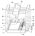
以下、図面に基づいて本発明の実施例について詳細に説明する。まず、図1を参照して、本発明の実施形態に係る工作機1の構成について説明する。図1は工具を備えていない状態である。本実施形態における工作機1は、枠体11と、枠体11を構成する載置面に対して垂直に設けられた一対の側壁に架橋された2本一対のX軸シャフト22からなる。X軸シャフト22は、主軸50を工作機1の載置面に対して水平方向に案内する。主軸50は、取り付けられた工具を回転させて、ワークに対して工作を実施する。
<Configuration of machine tool>
Hereinafter, embodiments of the present invention will be described in detail with reference to the drawings. First, with reference to FIG. 1, the structure of the
X軸シャフト22に平行な方向を本発明の実施形態におけるX軸とし、工作機1の載置面に対して水平方向で、X軸に垂直な方向をY軸、X軸及びY軸に対して垂直な方向をZ軸と呼ぶ。不図示のX軸駆動モータはX軸シャフト22に平行に設けられたX軸駆動軸23を駆動させ、一対のX軸シャフト22及びX軸駆動軸23に組みつけられたX軸スライダ20が移動する。X軸スライダ20の移動に伴いX軸スライダ20に組みつけられた主軸50は、工作機1の載置面に対して水平方向に移動する。
The direction parallel to the
Y軸シャフト27はX軸に対して垂直に設けられ、不図示のY軸駆動モータはY軸シャフト27に平行に設けられたY軸駆動軸29を駆動させる。これにより、一対のY軸シャフト27及びY軸駆動軸29に組みつけられたY軸スライダ25が移動する。Y軸シャフト27と平行して、一対のマガジンシャフト67設けられ、マガジン保持部材69がマガジンシャフト67に組付けられ、Y軸スライダ25と連結し、Y軸の移動に伴って移動する。マガジン保持部材をY軸スライダと連結することによって、余分な駆動手段を無くしている。
The Y-
マガジン保持部材69には、工具マガジン30が組付けられる。工具マガジン30は、隔壁によって工具10の加工によるワークの切粉が入り込まないようにすることが好ましい。工具10は、交換を行いながら加工するため工具マガジン30に複数設置されている。
The
不図示のZ軸駆動モータの駆動力が駆動軸及び連結部によって伝わり、主軸50は、Z軸スライダ24に沿って、工作機1の載置面に対して垂直方向に移動する。X軸駆動モータやZ軸駆動モータは駆動力によって主軸50と連結する部材により主軸50を移動させる移動手段として機能する。これによって、主軸は三次元上2軸方向へ移動可能となっている。
A driving force of a Z-axis drive motor (not shown) is transmitted by the drive shaft and the connecting portion, and the
枠体11には底から下方に突出して床面に当接する複数本の脚部5が設けられる。載置場所において、工作機1は、これら脚部5によって枠体11の底部に組みつけられた作業台(テーブル)2と作業台2に固定する加工対象であるワークに対して安定した工作動作を得る。
The
工作機1の工具マガジン30の移動経路上には被衝突部材57が設けられている。工作機1には先端保持部材40に接触させ上下移動させる上下移動部材62と、上下移動させる上下駆動手段64が設けられている。
A
<制御構成>
次に、図2を参照して、第1の実施形態に係る工作機1の制御構成について説明する。工具格納装置は、制御構成として、制御部201を備える。制御部201は、CPU14、モータドライバ16、及びデータ記憶部17を備える。
<Control configuration>
Next, a control configuration of the
CPU14は、データ記憶部17に格納されている制御プログラム等を読み出して実行することにより工作機1を統括的に制御する。また、CPU14は、入力されたデータや信号に基づいて各種の演算を行う。モータドライバ16は、CPU14からの指示に基づいて駆動手段として機能するモータ12を駆動する。このモータ12の駆動により、主軸50が駆動され、エンコーダ13からの出力によりCPU14が主軸の位置を検知する。そして、モータ12の駆動によって主軸50が実際に移動した量(実際の位置)を検知することにより、ワークの位置や高さ方向のサイズを検知することができる。
The
データ記憶部17は、制御プログラムの他に、モータ12を駆動するための駆動パラメータやエンコーダ13からの出力と主軸の位置を関連づけるための情報等を記憶する。CPU14は、データ記憶部17に記憶されたデータに基づいて各種の演算を行い、エンコーダ13で読み込んだ位置に基づいて、ワークの位置等を検知する。
In addition to the control program, the
<ワーク>
本発明では、ワーク近傍へ主軸50を移動させるため、ワークサイズを予め知っている必要がある。そこで、本実施形態では、定形のワークサイズを数種類用意し、その中からユーザに選択させるようにする。定形のワークサイズは、例えば、以下の3タイプを用意する。
タイプ1:幅100mm、奥行き80mm、高さ15mm
タイプ2:幅100mm、奥行き80mm、高さ50mm
タイプ3:幅100mm、奥行き80mm、高さ100mm
これらのワークサイズをユーザが選択する方法として、必要に応じて随時入力してもよいし、又はNCプログラム中のNCコードによって指定してもよい。
<Work>
In the present invention, since the
Type 1: Width 100mm, Depth 80mm, Height 15mm
Type 2: Width 100mm, Depth 80mm, Height 50mm
Type 3: Width 100mm, Depth 80mm, Height 100mm
As a method for the user to select these work sizes, they may be input as needed, or may be designated by an NC code in the NC program.
したがって、特別なNCコードを用意し、例えば、NCコードの機能を、以下のように割り当てたとする。
M201・・・タイプ1のワークを使って加工する。
M202・・・タイプ2のワークを使って加工する。
M203・・・タイプ3のワークを使って加工する。
このとき、NCプログラム中に、M201というコードが現れたら、このNCプログラムはタイプ1(幅100mm、奥行き80mm、高さ15mm)のワークサイズで加工を行うという意味になる。このようにして、必要なワークサイズがわかるので、ワーク近傍まで主軸50を移動させることが可能となる。
Therefore, it is assumed that a special NC code is prepared, and for example, the function of the NC code is assigned as follows.
M201 ...
M202 ...
M203 ... Machining using type 3 workpiece.
At this time, if a code M201 appears in the NC program, this NC program means that machining is performed with a work size of type 1 (width 100 mm, depth 80 mm, height 15 mm). In this way, since the necessary work size is known, the
<高さ方向検知(ワークの高さ一定)>
次に、図3を参照して、作業台2に載置されるワークの高さが一定である場合の、ワークサイズ(高さ方向)の検出手順について説明する。以下で説明する処理は、CPU14がデータ記憶部17に格納されている制御プログラムを読み出して実行することにより実現される。ここでは、駆動部にステッピングモータを使用した場合の処理について説明する。
<Height direction detection (constant workpiece height)>
Next, a procedure for detecting the workpiece size (height direction) when the height of the workpiece placed on the work table 2 is constant will be described with reference to FIG. The process described below is realized by the
S101において、CPU14は、モータドライバ16を介してワークの上方に主軸50を位置決めする。この位置では、主軸50がワークに接触せず、脱調が発生していない状態となる。脱調とは、例えば、モータドライバ16に入力されるパルス信号にモータが追従できなくなる現象を意味する。脱調が発生すると、実際の移動位置と、指令された所定移動位置との差が発生する。この差のことを、以下では位置偏差と称する。位置偏差を許容する範囲を予め設定し、通常は、許容する範囲内に収まっているが、この範囲を超えると異常と判断し、動作を停止させる。
In S <b> 101, the
S102において、CPU14は、Z軸の駆動トルクを下げ、さらに、Z軸の位置偏差を許容する範囲を狭める。駆動トルクを下げる理由は、万が一、主軸50がワークに接触した際に、主軸50などのメカ機構の破損やワークの破損を最小限に抑えるためである。同様に、破損などの被害を抑えるために、位置偏差を許容する範囲を狭め、少しでも脱調が生じると、異常として検出し、動作を停止できるようにする。位置の検出は、例えばエンコーダ13を用いる。例えば、位置偏差が100パルス以上ずれた場合に異常だと判断していたとすると、この値を10パルスとすることで、位置偏差が10パルスを超えるとすぐに異常として検出し、動作を停止するようにできるため、破損などの被害を抑えられる。
In S102, the
S103において、CPU14は、ワークの高さを取得する。この値は、予め所定の値を設定しているか、値を随時入力できるようにしてもよい。または、前述のように、NCプログラム上のNCコードでワークサイズを指定できるように、特別なNCコードを用意してもよい。
In S103, the
S104において、CPU14は、Z軸を移動させ、主軸50をワークの上面ぎりぎりまで下降させる。そのために、Z軸の原点からどの程度離れた位置へ移動させるべきかを知る必要がある。この位置は、S103で取得したワークの高さに応じて、所定の値を決めておいてもよい。或いは、CPU14が随時計算してもよい。計算する場合は、ワークを乗せる作業台2の上面ぎりぎりの位置に主軸50がいるときのZ軸位置から、S103で取得したワークの高さを引いたものが、求める値となる。この計算結果に対して、実験や経験に基づき、補正を行ってもよい。また、主軸50の下降速度を遅くすることで、万が一、主軸50がワークに接触した際に、主軸50などのメカ機構の破損やワークの破損を最小限に抑えるようにする。
In S <b> 104, the
S105において、CPU14は、Z軸に脱調が起きたか否かを判定する。つまり、S104で行ったワークの上面位置へ主軸50を下降させる動作について、所定の位置へ位置決めを完了できたか否かを判定している。位置の検出は、エンコーダ13を用いる。脱調が発生したならば、S106へ進み、CPU14は、S103で設定したサイズよりも大きいワークだと判断し、S108に進む。一方、脱調が発生しなければS107へ進み、CPU14は、S103で設定したサイズか、それよりも小さいワークだと判断し、S108に進む。その後、S108において、CPU14は、S102で下げた駆動トルクを元に戻し、位置偏差を許容する範囲も元に戻し、処理を終了する。その後、CPU14は、S106又はS107で判断したワークのサイズに従って当該ワークへの工作を制御する。
In S105, the
<高さ方向検知(ワークの高さ不定)>
次に、図4を参照して、ワークの高さが一定でなく、所々異なっている場合のワークサイズを検知する検出手順について説明する。つまり、ワークの高さの測定ポイントが複数あることになる。以下で説明する処理は、CPU14がデータ記憶部17に格納されている制御プログラムを読み出して実行することにより実現される。ここでは、駆動部にステッピングモータを使用した場合の処理について説明する。
<Height direction detection (work height indefinite)>
Next, with reference to FIG. 4, the detection procedure for detecting the workpiece size when the workpiece height is not constant and varies in some places will be described. That is, there are a plurality of workpiece height measurement points. The process described below is realized by the
S201において、CPU14は、測定ポイント数を変数nに格納する。そして、カウンタ変数iを初期化する。この変数iは、測定ポイント番号を参照するために使われる。続いて、S202において、CPU14は、変数iをインクリメントする。S203において、CPU14は、第i点での、XY位置とワーク高さを取得する。これらの値は、予め入力されているか、必要に応じ随時入力するようにしてもよい。
In S201, the
S204において、CPU14は、S203で取得したXY位置へ主軸50を移動させる。この時のZ方向の位置は、ワークに接触しないように上方に逃げているものとする。S205において、CPU14は、図3のフローチャートを用いて説明したワークサイズ検知処理を実行する。ただし、S103で使うワーク高さは、S203で取得した値を使用する。
In S204, the
S206において、CPU14は、S205の結果が、所定サイズよりもワークサイズが大きいと判断しているならば、S207へ進み、CPU14は、所定サイズよりもワークサイズが大きいと判断し、処理を終了する。一方、S205の結果が、ワークが所定サイズ、又は所定サイズよりも小さいと判断しているならば、S208へ進む。S208において、CPU14は、測定ポイント番号を参照している変数iが、測定ポイント数を超えたか否か(n<i)を判定する。もし、n<iならば、S209に進み、CPU14は、ワークが所定サイズ、又は所定サイズよりも小さいと判断し、処理を終了する。もし、n<iでないならば、未だ測定していない測定ポイントがあると判断し、処理をS202へ戻す。
In S206, if the result of S205 determines that the work size is larger than the predetermined size, the
このように、ワークの高さが不定で、複数の測定ポイントがある場合は、各測定ポイントで図3で説明した検知処理を実行する。なお、ワークサイズが所定サイズよりも大きいと判断すると、その時点でまだ測定していないポイントがあったとしても測定を中止し、S207でワークが所定サイズよりも大きいと判断する。一方、S209でワークが所定サイズ以下であると判断する場合は、全ての測定ポイントでそのような結果が得られた場合となる。その後、CPU14は、S207又はS209で判断したワークのサイズに従って当該ワークへの工作を制御する。
As described above, when the workpiece height is indefinite and there are a plurality of measurement points, the detection process described with reference to FIG. 3 is executed at each measurement point. If it is determined that the workpiece size is larger than the predetermined size, the measurement is stopped even if there is a point that has not been measured at that time, and it is determined in S207 that the workpiece is larger than the predetermined size. On the other hand, when it is determined in S209 that the workpiece is not larger than the predetermined size, such a result is obtained at all measurement points. Thereafter, the
<幅方向検知(ワークの幅一定)>
次に、図5を参照して、ワークの幅が一定である場合に、ワークサイズ(幅方向)を検出する検出手順について説明する。以下で説明する処理は、CPU14がデータ記憶部17に格納されている制御プログラムを読み出して実行することにより実現される。ここでは、駆動部にステッピングモータを使用した場合の処理について説明する。
<Width direction detection (constant workpiece width)>
Next, a detection procedure for detecting the workpiece size (width direction) when the workpiece width is constant will be described with reference to FIG. The process described below is realized by the
S301において、CPU14は、ワークの右方に主軸50を位置決めする。ここでは、右方としているが左方としてもよい。Z方向の位置は、主軸50先端の位置がワークを乗せているプレートの上面に近くなるようにする。なお、この位置は、主軸50がワークに接触せず、脱調が発生していない状態とする。
In S301, the
S302において、CPU14は、X軸の駆動トルクを下げ、さらに、X軸の位置偏差を許容する範囲を狭める。続いて、S303において、CPU14は、ワークの幅を取得する。この値は、予め所定の値を設定しているか、又は値を随時入力できるようにしてもよい。或いは、前述のように、NCプログラム上のNCコードでワークサイズを指定できるように、特別なNCコードを用意してもよい。
In S <b> 302, the
S304において、CPU14は、X軸を駆動させ、ワークの右面ぎりぎりまで主軸50を移動させる。ワーク右面ぎりぎりの位置は、ワークの幅に応じて予め設定されている、または随時入力させてもよい。また、主軸50の移動速度を遅くすることで、万が一、主軸50がワークに接触した際に、主軸50などのメカ機構の破損やワークの破損を最小限に抑える。
In S <b> 304, the
S305において、CPU14は、X軸に脱調が起きたか否かを判定する。つまり、S304で行った、ワークの右面位置へ主軸50を移動させる動作について、所定の位置へ位置決めを完了できたか否かを判定している。位置の検出は、例えばエンコーダ13を用いる。脱調が発生したならば、S306へ進み、CPU14は、S303で設定したサイズ(所定サイズ)よりも大きいワークだと判断し、S308に進む。脱調が発生しなければS307へ進み、CPU14は、S303で設定したサイズか、それよりも小さいワークだと判断し、S308に進む。S308において、CPU14は、S302で下げた駆動トルクを元に戻し、位置偏差を許容する範囲も元に戻し、処理を終了する。その後、CPU14は、S306又はS307で判断したワークのサイズに従って当該ワークへの工作を制御する。なお、ここでは、測定ポイントが1つの場合について説明したが、幅方向において測定ポイントが複数ある場合には、図4と同様に各ポイントにおいて測定を実施する。
In S305, the
<奥行方向検知(ワークの奥行一定)>
次に、図6を参照して、ワークの奥行きが一定である場合に、ワークサイズ(奥行き方向)を検出する検出手順について説明する。以下で説明する処理は、CPU14がデータ記憶部17に格納されている制御プログラムを読み出して実行することにより実現される。ここでは、駆動部にステッピングモータを使用した場合の処理について説明する。
<Depth direction detection (constant workpiece depth)>
Next, a detection procedure for detecting the workpiece size (depth direction) when the workpiece depth is constant will be described with reference to FIG. The process described below is realized by the
S401において、CPU14は、ワークの手前に主軸50を位置決めする。ここでは、手前としているがワークの奥側でもよい。Z方向の位置は、主軸50先端の位置がワークを乗せているプレート上の面に近くなるようにする。なお、この位置は、主軸50がワークに接触せず、脱調が発生していない状態とする。
In S401, the
S402において、CPU14は、Y軸の駆動トルクを下げ、Y軸の位置偏差を許容する範囲を狭める。続いて、S403において、CPU14は、ワークの奥行きを取得する。この値は、予め所定の値を設定しているか、又は値を随時入力できるようにしてもよい。或いは、前述のように、NCプログラム上のNCコードでワークサイズを指定できるように、特別なNCコードを用意してもよい。
In S <b> 402, the
S404において、CPU14は、Y軸を駆動させてワークを移動させ、ワークの手前面ぎりぎりの位置に主軸50が位置するようにする。ワーク手前面ぎりぎりの位置は、ワークの奥行きに応じて予め設定されているか、または随時入力できてもよい。また、主軸50の移動速度を遅くすることで、万が一、主軸50がワークに接触した際に、主軸50などのメカ機構の破損やワークの破損を最小限に抑える。
In S <b> 404, the
S405において、CPU14は、Y軸に脱調が起きたか否かを判定する。つまり、S404で行った、ワークを移動させてワークの手前面位置ぎりぎりに主軸50が位置するようにさせる動作について、所定の位置へ位置決めを完了できたか否かを判定している。位置の検出は、例えばエンコーダ13を用いる。脱調が発生したならば、S406へ進み、CPU14は、S403で設定したサイズよりも大きいワークだと判断する。一方、脱調が発生しなければS407へ進み、CPU14は、S403で設定したサイズか、それよりも小さいワークだと判断する。その後、S408へ進み、CPU14は、S402で下げた駆動トルクを元に戻し、位置偏差を許容する範囲も元に戻し、処理を終了する。なお、ここでは、測定ポイントが1つの場合について説明したが、奥行方向において測定ポイントが複数ある場合には、図4と同様に各ポイントにおいて測定を実施する。
In S405, the
以上説明したように、本実施形態に係る工作機1は、作業台2に載置されたワークのサイズ(高さ方向、幅方向、奥行き方向)が所定サイズ、例えば、操作者から入力された(選択された)サイズより大きいか、当該サイズ以下であるかを判定する。具体的には、本工作機1は、ワークを加工するために工具を取り付ける主軸50を用いて、所定サイズを考慮して主軸50をワーク方向に駆動させ、主軸を駆動するモータ12に脱調が発生したか否かを検知することにより、ワークのサイズを判断する。なお、主軸50をワーク方向に駆動させる際には、駆動トルクを下げてワーク等が破損しないように制御する。これにより、本実施形態に係る工作機1は、作業台2にワークを装着したままワークサイズを判断し、ワークサイズの差異による加工の失敗・工具破損を低コストで防ぐことができる。その後、CPU14は、S406又はS407で判断したワークのサイズに従って当該ワークへの工作を制御する。
As described above, in the
本発明は、上記実施形態に限らず様々な変形が可能である。例えば、上記実施形態では、作業台2に載置されたワークへ向けて主軸を駆動することにより、ワークのサイズを判断していたが、主軸を固定し、作業台2を駆動することによってワークを移動させてワークのサイズを判断するようにしてもよい。 The present invention is not limited to the above embodiment, and various modifications can be made. For example, in the above embodiment, the size of the workpiece is determined by driving the spindle toward the workpiece placed on the work table 2. However, the workpiece is determined by fixing the spindle and driving the work table 2. The size of the workpiece may be determined by moving the.
<その他の実施形態>
また、本発明は、以下の処理を実行することによっても実現される。即ち、上述した実施形態の機能を実現するソフトウェア(プログラム)を、ネットワーク又は各種記憶媒体を介してシステム或いは装置に供給し、そのシステム或いは装置のコンピュータ(又はCPUやMPU等)がプログラムを読み出して実行する処理である。
<Other embodiments>
The present invention can also be realized by executing the following processing. That is, software (program) that realizes the functions of the above-described embodiments is supplied to a system or apparatus via a network or various storage media, and a computer (or CPU, MPU, etc.) of the system or apparatus reads the program. It is a process to be executed.
Claims (8)
取り付けられた工具を回転させる主軸と、
前記主軸に取り付けられた工具によって工作が行われるワークを取り付けるテーブルと、
前記テーブルに載置されるワークのサイズを取得する取得手段と、
前記取得手段によって取得した前記ワークのサイズに従って、前記テーブルに載置されたワークの近傍に前記主軸を駆動する駆動手段と、
前記駆動手段が脱調した場合には、前記ワークの実際のサイズが前記取得手段によって取得されたワークのサイズよりも大きい場合として前記ワークに対する工作を制御し、前記駆動手段が脱調しなかった場合には、前記ワークの実際のサイズが前記取得手段によって取得されたワークのサイズ以下である場合として前記ワークに対する工作を制御する制御手段と
を備えることを特徴とする工作機。 A machine tool,
A spindle that rotates the attached tool;
A table for mounting a workpiece to be machined by a tool attached to the spindle;
Obtaining means for obtaining a size of a workpiece placed on the table;
Driving means for driving the spindle in the vicinity of the work placed on the table according to the size of the work obtained by the obtaining means;
When the driving means stepped out, the work on the workpiece was controlled as if the actual size of the workpiece was larger than the size of the workpiece acquired by the acquiring means, and the driving means did not step out. In this case, the machine tool includes: a control unit that controls a work on the workpiece as a case where an actual size of the workpiece is equal to or smaller than a size of the workpiece acquired by the acquisition unit.
前記制御手段は、
前記上方から前記主軸を前記ワークへ近づけた場合は、前記ワークの高さに関するサイズを判断し、
前記左方又は右方から前記主軸を前記ワークへ近づけた場合は、前記ワークの幅に関するサイズを判断し、
前記手前又は奥から前記主軸を前記ワークへ近づけた場合は、前記ワークの奥行に関するサイズを判断することを特徴とする請求項1又は2に記載の工作機。 When the driving means moves the spindle to the vicinity of the work, the driving means moves the spindle closer to the work from above, left, right, near, or the back of the work placed on the table. ,
The control means includes
When approaching the spindle from the upper side to the work, determine the size related to the height of the work,
When approaching the spindle from the left or right side to the work, determine the size related to the width of the work,
3. The machine tool according to claim 1, wherein when the main shaft is brought close to the work from the front or the back, a size related to the depth of the work is determined.
前記ワークの高さ、幅、又は奥行に関するサイズを判断する場合に、それぞれ複数のポイントにおいて、前記駆動手段を用いて前記主軸を前記ワークの近傍に移動させ、
少なくとも1つのポイントにおいて前記駆動手段が脱調した場合には、前記ワークの実際のサイズが前記取得手段によって取得されたワークのサイズよりも大きい場合として前記ワークに対する工作を制御し、全てのポイントにおいて前記駆動手段が脱調しなかった場合には、前記ワークの実際のサイズが前記取得手段によって取得されたワークのサイズ以下である場合として前記ワークに対する工作を制御することを特徴とする請求項3に記載の工作機。 The control means includes
When determining the size related to the height, width, or depth of the workpiece, at each of a plurality of points, move the spindle to the vicinity of the workpiece using the driving means,
When the driving means steps out at at least one point, the work on the work is controlled as if the actual size of the work is larger than the size of the work obtained by the obtaining means, and at all points 4. If the drive means does not step out, the work on the work is controlled as if the actual size of the work is less than or equal to the size of the work acquired by the acquisition means. The machine tool described in 1.
取り付けられた工具を回転させる主軸と、
前記主軸に取り付けられた工具によって工作が行われるワークを取り付けるテーブルと、
前記テーブルに載置されるワークのサイズを取得する取得手段と、
前記取得手段によって取得した前記ワークのサイズに従って、前記テーブルを駆動して、前記主軸の近傍に該テーブルに載置されたワークを移動させる駆動手段と、
前記駆動手段が脱調した場合には、前記ワークの実際のサイズが前記取得手段によって取得されたワークのサイズよりも大きい場合として前記ワークに対する工作を制御し、前記駆動手段が脱調しなかった場合には、前記ワークの実際のサイズが前記取得手段によって取得されたワークのサイズ以下である場合として前記ワークに対する工作を制御する制御手段と
を備えることを特徴とする工作機。 A machine tool,
A spindle that rotates the attached tool;
A table for mounting a workpiece to be machined by a tool attached to the spindle;
Obtaining means for obtaining a size of a workpiece placed on the table;
Driving means for driving the table in accordance with the size of the workpiece acquired by the acquiring means to move the workpiece placed on the table in the vicinity of the spindle;
When the driving means stepped out, the work on the workpiece was controlled as if the actual size of the workpiece was larger than the size of the workpiece acquired by the acquiring means, and the driving means did not step out. In this case, the machine tool includes: a control unit that controls a work on the workpiece as a case where an actual size of the workpiece is equal to or smaller than a size of the workpiece acquired by the acquisition unit.
前記テーブルに載置されるワークのサイズを取得する取得ステップと、
前記取得ステップにおいて取得した前記ワークのサイズに従って、前記テーブルに載置されたワークの近傍に前記主軸を駆動する駆動ステップと、
前記駆動ステップにおいて脱調が発生した場合には、前記ワークの実際のサイズが前記取得ステップにおいて取得されたワークのサイズよりも大きい場合として前記ワークに対する工作を制御し、前記駆動ステップにおいて脱調が発生しなかった場合には、前記ワークの実際のサイズが前記取得ステップにおいて取得されたワークのサイズ以下である場合として前記ワークに対する工作を制御する制御ステップと
を実行することを特徴とする工作機の制御方法。 A machine tool control method comprising: a spindle for rotating an attached tool; and a table for attaching a workpiece to be machined by the tool attached to the spindle,
An acquisition step of acquiring a size of a workpiece placed on the table;
A driving step of driving the spindle in the vicinity of the work placed on the table according to the size of the work obtained in the obtaining step;
When step-out occurs in the driving step, the work on the workpiece is controlled as if the actual size of the workpiece is larger than the size of the workpiece acquired in the acquisition step, and step-out occurs in the driving step. And a control step for controlling a work on the workpiece when the actual size of the workpiece is equal to or smaller than the size of the workpiece acquired in the acquisition step. Control method.
前記テーブルに載置されるワークのサイズを取得する取得ステップと、
前記取得ステップにおいて取得した前記ワークのサイズに従って、前記テーブルを駆動して、前記主軸の近傍に該テーブルに載置されたワークを移動させる駆動ステップと、
前記駆動ステップにおいて脱調が発生した場合には、前記ワークの実際のサイズが前記取得ステップにおいて取得されたワークのサイズよりも大きい場合として前記ワークに対する工作を制御し、前記駆動ステップにおいて脱調が発生しなかった場合には、前記ワークの実際のサイズが前記取得ステップにおいて取得されたワークのサイズ以下である場合として前記ワークに対する工作を制御する制御ステップと
を実行することを特徴とする工作機の制御方法。 A machine tool control method comprising: a spindle for rotating an attached tool; and a table for attaching a workpiece to be machined by the tool attached to the spindle,
An acquisition step of acquiring a size of a workpiece placed on the table;
A driving step of driving the table according to the size of the workpiece acquired in the acquiring step and moving the workpiece placed on the table in the vicinity of the spindle;
When step-out occurs in the driving step, the work on the workpiece is controlled as if the actual size of the workpiece is larger than the size of the workpiece acquired in the acquisition step, and step-out occurs in the driving step. And a control step for controlling a work on the workpiece when the actual size of the workpiece is equal to or smaller than the size of the workpiece acquired in the acquisition step. Control method.
Priority Applications (1)
| Application Number | Priority Date | Filing Date | Title |
|---|---|---|---|
| JP2012276094A JP2014117785A (en) | 2012-12-18 | 2012-12-18 | Machine tool and machine tool control method |
Applications Claiming Priority (1)
| Application Number | Priority Date | Filing Date | Title |
|---|---|---|---|
| JP2012276094A JP2014117785A (en) | 2012-12-18 | 2012-12-18 | Machine tool and machine tool control method |
Publications (1)
| Publication Number | Publication Date |
|---|---|
| JP2014117785A true JP2014117785A (en) | 2014-06-30 |
Family
ID=51173097
Family Applications (1)
| Application Number | Title | Priority Date | Filing Date |
|---|---|---|---|
| JP2012276094A Pending JP2014117785A (en) | 2012-12-18 | 2012-12-18 | Machine tool and machine tool control method |
Country Status (1)
| Country | Link |
|---|---|
| JP (1) | JP2014117785A (en) |
-
2012
- 2012-12-18 JP JP2012276094A patent/JP2014117785A/en active Pending
Similar Documents
| Publication | Publication Date | Title |
|---|---|---|
| JP6023085B2 (en) | Manufacturing device with sensing means for sensing tool position and set-up method | |
| EP1962160A2 (en) | Machine tool having workpiece reference position setting function by contact detection | |
| JP6013139B2 (en) | Tool length measuring method and machine tool | |
| US20130071198A1 (en) | Numerically-controlled machine tool | |
| JP2016083729A (en) | Geometric error identification system, and geometric error identification method | |
| JP5673855B2 (en) | Machine Tools | |
| US11221201B2 (en) | Profile measuring machine and profile measuring method | |
| EP3192611A1 (en) | Calibration device and method | |
| JP2014087883A (en) | Method for measuring tool length, and machine tool | |
| JP2001269841A (en) | Method and device for automatically correcting measurement error | |
| CN112388392A (en) | Onboard measuring device, machine tool, and onboard measuring method | |
| JP4172614B2 (en) | Ball screw feed drive correction method | |
| US20030037588A1 (en) | System and method of calibrating a multi-toolhead machine | |
| JP2018079526A (en) | Machine tool and working method | |
| CN108919746B (en) | Thermal error testing and analyzing method of rotary swing table | |
| JP6425009B2 (en) | Three-dimensional measuring machine and shape measuring method using the same | |
| JP2006323773A (en) | Acquisition method for drive controlling correction data | |
| JP2014117785A (en) | Machine tool and machine tool control method | |
| JP5846400B2 (en) | Machine tool and its thermal deformation correction method | |
| JP2005335036A (en) | Cylindrical grinding device and method for measuring outer diameter of workpiece | |
| JP2002039743A (en) | Measuring instrument | |
| JP2004322255A (en) | Machine tool with straight line position measuring instrument | |
| JP4908755B2 (en) | Grinding machine calibration method and recalibration method and machine having a device for performing the method | |
| JPH05185304A (en) | Automatic lathe | |
| JP2006192516A (en) | Machine tool, and work measuring device and method |