JP2014114663A - Pipe body cutting preprocessor - Google Patents

Pipe body cutting preprocessor Download PDF

Info

Publication number
JP2014114663A
JP2014114663A JP2012271375A JP2012271375A JP2014114663A JP 2014114663 A JP2014114663 A JP 2014114663A JP 2012271375 A JP2012271375 A JP 2012271375A JP 2012271375 A JP2012271375 A JP 2012271375A JP 2014114663 A JP2014114663 A JP 2014114663A
Authority
JP
Japan
Prior art keywords
cutting
tube
deposit
deposit removing
drilling
Prior art date
Legal status (The legal status is an assumption and is not a legal conclusion. Google has not performed a legal analysis and makes no representation as to the accuracy of the status listed.)
Granted
Application number
JP2012271375A
Other languages
Japanese (ja)
Other versions
JP6031345B2 (en
Inventor
Kazuhiko Takahashi
和彦 高橋
Naoki Takahashi
直樹 高橋
Hiroshi Hasegawa
博 長谷川
Kazuo Akiyama
和夫 秋山
Hiroyuki Kofunato
博幸 小舟戸
Katsutoshi Noguchi
勝俊 野口
Current Assignee (The listed assignees may be inaccurate. Google has not performed a legal analysis and makes no representation or warranty as to the accuracy of the list.)
NIIGATA SENSUI KOGYO CO Ltd
RES AND DEV Inc
RESEARCH AND DEVELOPMENT Inc
Original Assignee
NIIGATA SENSUI KOGYO CO Ltd
RES AND DEV Inc
RESEARCH AND DEVELOPMENT Inc
Priority date (The priority date is an assumption and is not a legal conclusion. Google has not performed a legal analysis and makes no representation as to the accuracy of the date listed.)
Filing date
Publication date
Application filed by NIIGATA SENSUI KOGYO CO Ltd, RES AND DEV Inc, RESEARCH AND DEVELOPMENT Inc filed Critical NIIGATA SENSUI KOGYO CO Ltd
Priority to JP2012271375A priority Critical patent/JP6031345B2/en
Publication of JP2014114663A publication Critical patent/JP2014114663A/en
Application granted granted Critical
Publication of JP6031345B2 publication Critical patent/JP6031345B2/en
Expired - Fee Related legal-status Critical Current
Anticipated expiration legal-status Critical

Links

Images

Abstract

PROBLEM TO BE SOLVED: To provide an epoch-making pipe body cutting preprocessor excellent in practicality, capable of reducing the effort of an operator in drilling work and deposit removal work as a preliminary treatment when performing pipe body cutting and allowing these operations to be performed efficiently and at low cost.SOLUTION: A pipe body cutting preprocessor is equipped with: a drilling device 3 for drilling a discharge hole 2 for discharging a combustible gas in a pipe body 1 before cutting the pipe body 1; and a deposit removal device 6 for removing deposit 4 adhering to a cutting position surface of the pipe body 1 to form a deposit removal part 5 for cutting. On an annular guide part 7 detachably attached to a periphery of the pipe body 1 so as to surround the pipe body 1, a circularly moving part 8 moving circularly along the annular guide part 7 is provided. The drilling device 3 and the deposit removal device 6 are provided on the circularly moving part 8, and at least the drilling device 3 is freely operable for drilling by remote control operation.

Description

本発明は、例えば、海底地盤に根入れされた鋼管等の管体を撤去する際に、この管体を水中酸素アーク切断する前に、管体内部の可燃性ガスを排出するために排出孔を穿孔すると共に、この管体の切断位置の表面に付着している海生生物等の付着物を除去する管体切断前処理装置に関するものである。   For example, when removing a pipe body such as a steel pipe embedded in the seabed ground, the present invention provides a discharge hole for discharging a combustible gas inside the pipe body before cutting the pipe underwater oxygen arc. And a tube cutting pretreatment apparatus for removing attached matter such as marine organisms attached to the surface of the cutting position of the tube.

例えば、海底地盤に根入れされた鋼管等の管体を撤去する際、この管体を水中酸素アーク切断する前に、切断前処理として、管体内に溜まっている可燃性ガスを管体外部に排出する可燃性ガス排出作業や切断作業の妨げとなる管体表面に付着している海生生物等の付着物を除去する付着物除去作業を行っている。   For example, when removing a tubular body such as a steel pipe that has been embedded in the seabed ground, before cutting this tubular body with an oxygen arc underwater, as a pre-cutting treatment, combustible gas accumulated in the tubular body is exposed to the outside of the tubular body. The deposit removal work is carried out to remove deposits such as marine organisms adhering to the surface of the tubular body which hinders the discharge of combustible gas to be discharged and the cutting operation.

この可燃性ガス排出作業では、穿孔機を用いて管体に可燃性ガスを排出するための排出孔を穿孔する穿孔作業が行われ、また、付着物除去作業では、スクレーパ等の除去装置(除去具)を用いて、管体表面に付着している付着物をこの管体の周方向に沿って削り落として切断位置をきれいにする作業が行われ、従来、これらの作業は、作業者(潜水士)が海中に潜り、手持ちの穿孔機や除去装置を用いて人力で行っていた。   In this flammable gas discharge work, a piercing work for piercing a discharge hole for discharging the flammable gas into the pipe body using a punching machine is performed, and in the deposit removal work, a removal device such as a scraper (removal) The work that cleans the cutting position by scraping off the adhering material adhering to the surface of the tubular body along the circumferential direction of the tubular body is performed using these tools. Was submerged in the sea and carried out manually using a hand-held drilling machine and removal device.

しかしながら、この海中でのこれらの作業は、作業者は海中に浮遊した状態で作業しなければならないため、作業反力を取り難く、非常に労力を要する厄介な作業であり、また、海中で作業反力を得るために体を固定するための足場を設置した場合は、この足場の設置に多大なコストが掛かっていた。   However, this work in the sea is a troublesome work that requires a lot of labor because it is difficult for the worker to take a reaction force because the worker must work while floating in the sea. In the case of installing a scaffold for fixing the body in order to obtain a reaction force, the installation of this scaffold has been costly.

本発明は、上述のような現状に鑑み、管体切断時の前処理である穿孔作業及び付着物除去作業において、作業者の労力を軽減し、これらの作業を効率良く且つ低コストで行うことができる実用性に優れた画期的な管体切断前処理装置を提供することを目的とする。   In view of the present situation as described above, the present invention reduces the labor of an operator and performs these operations efficiently and at low cost in the drilling operation and the deposit removal operation, which are pretreatments at the time of cutting the tube. It is an object of the present invention to provide an innovative tube cutting pretreatment apparatus that is excellent in practicality.

添付図面を参照して本発明の要旨を説明する。   The gist of the present invention will be described with reference to the accompanying drawings.

管体1を切断する前にこの管体1内の可燃性ガスを排出するための排出孔2を穿孔する穿孔装置3と、前記管体1の切断位置表面に付着した付着物4を除去して切断用付着物除去部5を形成する付着物除去装置6とを備えた管体切断前処理装置であって、前記管体1を囲むようにこの管体1周囲に着脱自在に取り付ける環状ガイド部7に、この環状ガイド部7に沿って周回移動する周回移動部8を設け、この周回移動部8に前記穿孔装置3と前記付着物除去装置6とを設け、少なくとも前記穿孔装置3を遠隔操作により穿孔作動自在に設けたことを特徴とする管体切断前処理装置に係るものである。   Before cutting the tube body 1, the perforation device 3 for drilling the discharge hole 2 for discharging the flammable gas in the tube body 1 and the deposit 4 attached to the cutting position surface of the tube body 1 are removed. An apparatus for pre-cutting a tube body provided with a deposit removing device 6 for forming a cutting deposit removing section 5, which is detachably attached around the tube body 1 so as to surround the tube body 1. The part 7 is provided with a revolving movement part 8 that revolves around the annular guide part 7, the revolving movement part 8 is provided with the perforating device 3 and the deposit removing device 6, and at least the perforating apparatus 3 is remotely connected. The present invention relates to a pretreatment device for cutting a tubular body, which is provided so as to be pierced by operation.

また、前記穿孔装置3により穿孔した前記排出孔2よりも前記管体1の長さ方向の一方側若しくは他方側に前記付着物除去装置6を位置させ、この付着物除去装置6を前記環状ガイド部7に沿って前記周回移動部8を介して周回移動させて前記管体1表面に付着している付着物4を除去して前記切断用付着物除去部5を形成するように構成したことを特徴とする請求項1記載の管体切断前処理装置に係るものである。   Further, the deposit removing device 6 is positioned on one side or the other side in the length direction of the tubular body 1 with respect to the discharge hole 2 drilled by the punching device 3, and the deposit removing device 6 is connected to the annular guide. It is configured such that the adhering material 4 adhering to the surface of the tubular body 1 is removed by revolving around the part 7 via the orbiting moving unit 8 to form the cutting adhering material removing unit 5. The tube cutting pretreatment apparatus according to claim 1, characterized in that:

また、前記穿孔装置3の前記周回移動方向に並設状態に前記付着物除去装置6を設け、この付着物除去装置6を前記管体1の長さ方向に移動自在に設けて、前記付着物除去装置6により前記管体1表面に付着している付着物4を除去して穿孔用表面付着物除去部9を形成し、この穿孔用表面付着物除去部9に前記穿孔装置3により前記排出孔2を穿孔すると共に、前記付着物除去装置6を前記管体1の長さ方向に移動して前記排出孔2より前記管体1の長さ方向の一方側若しくは他方側に位置させて周回移動させることで、少なくとも前記管体1表面に付着している付着物4を半周以上除去して前記切断用付着物除去部5を形成するように構成したことを特徴とする請求項1,2のいずれか1項に記載の管体切断前処理装置に係るものである。   Further, the deposit removing device 6 is provided in a state of being arranged side by side in the circumferential movement direction of the perforating device 3, and the deposit removing device 6 is provided so as to be movable in the length direction of the tubular body 1, and the deposit The removal device 6 removes the deposits 4 adhering to the surface of the tubular body 1 to form a perforated surface deposit removal portion 9, and the perforation device 3 removes the perforated surface deposit removal portion 9 by the punching device 3. While piercing the hole 2, the deposit removing device 6 is moved in the length direction of the tube body 1 so as to be positioned on one side or the other side in the length direction of the tube body 1 from the discharge hole 2. 2. The structure according to claim 1, wherein the cutting deposit removing portion 5 is formed by removing at least half of the deposit 4 adhering to the surface of the tubular body 1 by moving the cut portion. This relates to the tube cutting pretreatment device according to any one of the above.

また、前記周回移動部8は、駆動ローラ10を付勢機構11による付勢力若しくは押圧機構による押圧力により前記環状ガイド部7に圧接して、この駆動ローラ10の駆動制御により前記環状ガイド部7に沿って自走周回移動する若しくは周回移動補助力が生じるように構成し、前記付着物除去装置6の除去工具部12に過負荷が生じようとした際には、前記付勢力若しくは前記押圧力に抗して前記駆動ローラ10が逃動しこの駆動ローラ10がスリップすることで、前記周回移動部8の周回移動が停止若しくは減速するように構成したことを特徴とする請求項1〜3のいずれか1項に記載の管体切断前処理装置に係るものである。   Further, the orbiting moving portion 8 presses the driving roller 10 against the annular guide portion 7 by the urging force of the urging mechanism 11 or the pressing force of the pressing mechanism, and the annular guide portion 7 is controlled by driving of the driving roller 10. When the overload is about to occur in the removal tool portion 12 of the deposit removing device 6, the biasing force or the pressing force is generated. The drive roller 10 is repelled against this and the drive roller 10 slips, so that the orbiting movement of the orbiting moving unit 8 is stopped or decelerated. The tube cutting pretreatment apparatus according to any one of the above items.

また、前記付着物除去装置6は、所定角度で前記管体1表面に圧接すると共に打撃振動して前記管体1表面に付着している付着物4を剥離除去するバイブレーションスクレーパ工具12を前記除去工具部12として採用したことを特徴とする請求項1〜4のいずれか1項に記載の管体切断前処理装置に係るものである。   The deposit removing device 6 removes the vibration scraper tool 12 that presses against the surface of the tubular body 1 at a predetermined angle and peels and removes the deposit 4 adhered to the surface of the tubular body 1 by striking vibration. It employ | adopted as the tool part 12, It concerns on the pipe body cutting pre-processing apparatus of any one of Claims 1-4 characterized by the above-mentioned.

また、前記周回移動部8に、前記穿孔装置3及び前記付着物除去装置6を設けると共に、前記付着物除去装置6により前記管体1に形成した前記切断用付着物除去部5を切断位置として切断する切断装置をも設けたことを特徴とする請求項1〜5のいずれか1項に記載の管体切断前処理装置に係るものである。   In addition, the perforating device 3 and the deposit removing device 6 are provided in the orbiting moving portion 8, and the cutting deposit removing portion 5 formed on the tubular body 1 by the deposit removing device 6 is used as a cutting position. 6. The tube cutting pretreatment device according to claim 1, further comprising a cutting device for cutting.

また、前記管体1は、下端が海底地盤に埋設された海中金属管支柱1であり、この海中金属管支柱1を高熱を伴う切断装置で切断する際の前処理として、この切断装置の切断位置の上方側に前記海中金属管支柱1内の可燃性ガスを排出するための前記排出孔2を穿孔するように前記穿孔装置3を構成し、この排出孔2よりも下方側の前記管体1表面に付着している付着物4である海生生物を除去して前記切断用付着物除去部5を形成するように前記付着物除去装置6を構成したことを特徴とする請求項1〜6のいずれか1項に記載の管体切断前処理装置に係るものである。   Moreover, the said pipe body 1 is the underwater metal pipe support | pillar 1 by which the lower end was embed | buried under the seabed ground, and cutting | disconnection of this cutting device as pre-processing at the time of cut | disconnecting this underwater metal pipe support | pillar 1 with a cutting device with high heat The perforating apparatus 3 is configured to perforate the exhaust hole 2 for exhausting the combustible gas in the submarine metal pipe column 1 above the position, and the tubular body below the exhaust hole 2 1. The deposit removing device 6 is configured to remove marine organisms as deposits 4 attached to a surface to form the cutting deposit removing unit 5. 6. The tube cutting pretreatment apparatus according to any one of items 6 to 6.

本発明は上述のように構成したから、管体切断時の前処理である穿孔作業及び付着物除去作業において、作業者の労力を軽減し、これらの作業を効率良く且つ低コストで行うことができる実用性に優れた画期的な管体切断前処理装置となる。   Since the present invention is configured as described above, it is possible to reduce the labor of the operator and perform these operations efficiently and at low cost in the drilling operation and the deposit removal operation, which are pretreatments at the time of cutting the tube. It is an epoch-making tube cutting pretreatment device with excellent practicality.

また、請求項2,3記載の発明においては、管体を切断する際の妨げとなる表面付着物を極めて容易に除去でき、切断位置となる切断用付着物除去部を容易に形成することができ、特に、請求項3記載の発明においては、排出孔を穿孔する際に、管体表面の穿孔位置に付着物が付着していて排出孔を穿孔しづらい状況でも、付着物除去装置で排出孔を穿孔する位置に付着している付着物を除去する付着物除去作業と、この付着物を除去した穿孔用表面付着物除去部に排出孔を穿孔する穿孔作業とを効率良く行うことができる極めて作業性に優れた画期的な管体切断前処理装置となる。   Further, in the inventions according to claims 2 and 3, surface deposits that hinder the cutting of the tube body can be removed very easily, and a cutting deposit removing portion that becomes a cutting position can be easily formed. In particular, in the invention according to claim 3, when the discharge hole is drilled, the deposit is removed by the deposit removing device even when the deposit is attached to the drilling position on the surface of the tube and it is difficult to drill the discharge hole. It is possible to efficiently perform the deposit removing operation for removing the deposit attached to the hole drilling position and the drilling operation for drilling the discharge hole in the surface deposit removing portion for drilling from which the deposit is removed. It becomes an innovative tube cutting pretreatment device with extremely excellent workability.

また、請求項4記載の発明においては、付着物除去装置が付着物に引っ掛かり周回移動不能となった場合にでも、付着物除去装置が破損しない構成を極めて簡易な構成で容易に設計実現可能とする画期的な管体切断前処理装置となる。   Further, in the invention described in claim 4, even when the deposit removing device is caught by the deposit and becomes unable to move around, it is possible to easily realize a configuration in which the deposit removing device is not damaged with a very simple configuration. It becomes an innovative tube cutting pretreatment device.

また、請求項5記載の発明においては、一層効率良く管体表面に付着している付着物を除去することができる作業性に優れた管体切断前処理装置となる。   In the invention according to claim 5, the tubular body cutting pretreatment apparatus is excellent in workability and can remove deposits adhered to the surface of the tubular body more efficiently.

また、請求項6記載の発明においては、管体切断時の前処理である穿孔作業及び付着物除去作業と管体切断作業との全ての作業を本発明の管体切断前処理装置で行うことができ、一層効率良く管体の切断作業を行うことができる画期的な管体切断前処理装置となる。   Further, in the invention described in claim 6, all the operations of the drilling operation and the deposit removal operation and the tube cutting operation, which are pretreatments at the time of cutting the tube, are performed by the tube cutting pretreatment apparatus of the present invention. Therefore, it is an epoch-making tube cutting pretreatment device that can perform the tube cutting operation more efficiently.

また、請求項7記載の発明においては、内部に可燃性ガスが存在し爆発の恐れがある海底地盤に根入れした海中金属管支柱を、効率的且つ極めて安全に切断することができる実用性に優れた画期的な管体切断前処理装置となる。   Further, in the invention described in claim 7, in the practicality capable of efficiently and extremely safely cutting the underwater metal pipe column embedded in the seabed ground where there is a combustible gas and there is a risk of explosion. It is an excellent and innovative tube cutting pretreatment device.

本実施例を示す斜視図である。It is a perspective view which shows a present Example. 本実施例を示す平面図である。It is a top view which shows a present Example. 本実施例を示す説明平面図である。It is a description top view which shows a present Example. 本実施例を海中金属管支柱に装着した状態を示す説明正面図である。It is explanatory front view which shows the state with which the present Example was mounted | worn with the underwater metal pipe support | pillar. 本実施例の係止爪部を示す説明側断面図である。It is explanatory side sectional drawing which shows the latching claw part of a present Example. 本実施例の要部を示す説明平面図である。It is explanatory top view which shows the principal part of a present Example. 本実施例の要部を示す説明平面図である。It is explanatory top view which shows the principal part of a present Example. 本実施例の要部を示す説明側断面図である。It is explanatory side sectional drawing which shows the principal part of a present Example. 本実施例の要部を示す説明側断面図である。It is explanatory side sectional drawing which shows the principal part of a present Example. 本実施例の要部を示す説明側断面図である。It is explanatory side sectional drawing which shows the principal part of a present Example. 本実施例の要部を示す説明側断面図である。It is explanatory side sectional drawing which shows the principal part of a present Example. 本実施例の要部を示す説明側断面図である。It is explanatory side sectional drawing which shows the principal part of a present Example. 本実施例の要部を示す説明側面図である。It is explanatory side view which shows the principal part of a present Example. 本実施例の穿孔装置及び付着物除去装置の移動機構を示す説明図である。It is explanatory drawing which shows the moving mechanism of the punching apparatus of this Example, and a deposit removal apparatus. 本実施例の使用状態を示す説明概略図である。It is explanatory description which shows the use condition of a present Example. 本実施例を用いて管体切断前処理を施した状態の海中金属管支柱を示す説明斜視図である。It is a description perspective view which shows the submarine metal pipe support | pillar of the state which performed the pipe body cutting | disconnection pretreatment using a present Example. 本実施例を用いて管体切断前処理を施した状態の海中金属管支柱を示す説明断面図である。It is explanatory sectional drawing which shows the underwater metal pipe support | pillar of the state which performed the pipe body cutting | disconnection pretreatment using a present Example.

好適と考える本発明の実施形態を、図面に基づいて本発明の作用を示して簡単に説明する。   An embodiment of the present invention which is considered to be suitable will be briefly described with reference to the drawings showing the operation of the present invention.

管体1の周囲に、この管体1を囲むようにして環状ガイド部7を取り付けて、本発明を管体1に装着する。   An annular guide portion 7 is attached around the tube body 1 so as to surround the tube body 1, and the present invention is attached to the tube body 1.

これにより、穿孔装置3及び付着物除去装置6は、環状ガイド部7を介して管体1に装着されたこととなり、従来のように、作業者が手持ちしなくても作業が可能となり、これによって、作業者は海中で作業反力を得るという非常に厄介な作業を強いられることが無くなり、また、作業者が作業反力を得るためにコストを掛けて足場を設置する必要も無くなるので、管体1切断時の前処理である穿孔作業及び付着物除去作業において、これらの作業の作業者への負担を軽減し、効率良く且つ低コストで行うことができる実用性に優れた画期的な管体切断前処理装置となる。   As a result, the punching device 3 and the deposit removing device 6 are attached to the tube body 1 via the annular guide portion 7, and the work can be performed without the hand of the operator as in the prior art. By this, the worker is not forced to perform a very troublesome work of obtaining work reaction force in the sea, and it is also unnecessary for the worker to install a scaffolding at a cost to obtain the work reaction force. In the drilling work and deposit removal work, which are pretreatments when cutting the tubular body 1, the burden on the workers of these work is reduced, and it is an epoch-making breakthrough excellent in practicality that can be performed efficiently and at low cost. Tube pre-cutting device.

しかも、本発明は、付着物除去装置6を環状ガイド部7に周回移動自在に設けた周回移動部8によって管体1表面に沿って周回移動自在に設けた構成としたので、管体1の切断位置表面に付着した付着物4を除去して切断用付着物除去部5を形成する際も、極めて容易に、且つ効率良く、管体1表面に付着している付着物4をこの管体1の周方向に沿って除去して管体1の切断位置となる切断用付着物除去部5を形成することができ、管体1表面に付着した海生生物等の付着物4に切断を妨げられることが無く、また、切断位置も明確になり、切断作業を効率良く行うことができる実用性に優れた画期的な管体切断前処理装置となる。   In addition, the present invention has a configuration in which the deposit removing device 6 is provided so as to be capable of circular movement along the surface of the tubular body 1 by the circumferential movement portion 8 provided in the annular guide portion 7 so as to be capable of circular movement. When the deposit 4 attached to the cutting position surface is removed to form the cutting deposit removing section 5, the deposit 4 attached to the surface of the tube 1 is very easily and efficiently formed. It is possible to form a cutting deposit removing portion 5 that is removed along the circumferential direction of the tube 1 to be a cutting position of the tube body 1, and cuts the deposit 4 such as marine organisms attached to the surface of the tube body 1. There is no hindrance, the cutting position is clarified, and it becomes an epoch-making tube cutting pretreatment apparatus excellent in practicality that can efficiently perform the cutting operation.

また、例えば、海底地盤に根入れされた鋼管等の管体1を切断する場合は、内部に海底地盤中から漏出した天然ガス等の可燃性ガスが溜まっている可能性があり、この可燃性ガスが溜まっている状態の管体1を穿孔装置3で穿孔すると、穿孔時に生じた火花が可燃性ガスに引火し爆発する恐れがあるが、この点、本発明は、穿孔装置3を遠隔操作により穿孔作動自在に設けた構成としたので、穿孔作業時は、作業者は穿孔現場にいなくても良く、穿孔現場から離れた安全な場所、例えば、海上に停泊している作業船13上で穿孔装置3を遠隔操作して安全な環境で穿孔作業を行うことができる画期的な管体切断前処理装置となる。   In addition, for example, when cutting the tubular body 1 such as a steel pipe embedded in the seabed ground, there is a possibility that flammable gas such as natural gas leaked from the seabed ground is accumulated inside, and this flammability. When the tube 1 in a state where gas is accumulated is drilled by the drilling device 3, the spark generated at the time of drilling may ignite the combustible gas and explode. However, in this respect, the drilling device 3 is operated remotely. Therefore, when drilling work, the operator does not have to be at the drilling site, and a safe place away from the drilling site, for example, on the work ship 13 anchored at sea. Thus, it becomes an epoch-making tube cutting pretreatment apparatus that can perform the drilling work in a safe environment by remotely operating the drilling apparatus 3.

本発明の具体的な実施例について図面に基づいて説明する。   Specific embodiments of the present invention will be described with reference to the drawings.

本実施例は、管体1を切断する前にこの管体1内の可燃性ガスを排出するための排出孔2を穿孔する穿孔装置3と、前記管体1の切断位置表面に付着した付着物4を除去して切断用付着物除去部5を形成する付着物除去装置6とを備えた管体切断前処理装置であって、前記管体1を囲むようにこの管体1周囲に着脱自在に取り付ける環状ガイド部7に、この環状ガイド部7に沿って周回移動する周回移動部8を設け、この周回移動部8に前記穿孔装置3と前記付着物除去装置6とを設け、少なくとも前記穿孔装置3を遠隔操作により穿孔作動自在に設けたものである。   In this embodiment, before the tube body 1 is cut, a perforation device 3 for perforating a discharge hole 2 for discharging the combustible gas in the tube body 1 and the attachment position attached to the surface of the tube body 1 at the cutting position. A tube body cutting pretreatment device including an attachment removing device 6 that removes the kimono 4 and forms an attachment removing portion 5 for cutting, and is attached to and detached from the tube body 1 so as to surround the tube body 1. An annular guide portion 7 that is freely attached is provided with a circumferential movement portion 8 that moves around the annular guide portion 7, and the perforation device 3 and the deposit removal device 6 are provided at the circumferential movement portion 8, at least The punching device 3 is provided so as to be drillable by remote control.

具体的には、本実施例は、桟橋の基礎となる海底地盤に根入れされた海中金属管支柱1を撤去する際に、この海中金属管支柱1を水中酸素アーク切断する前に、海中にて、海中金属管支柱1内に存在する可燃性ガスを排出するための排出孔2を海中金属管支柱1周面に穿孔する穿孔作業と、この海中金属管支柱1の切断位置表面に付着し切断作業の妨げとなる海生生物等の付着物4を除去する付着物除去作業との二つの異なる作業を一台で行うことができるように構成したものである。   Specifically, in this embodiment, when removing the underwater metal pipe strut 1 that is embedded in the seabed ground that is the foundation of the pier, before the underwater oxygen arc cutting of the underwater metal pipe strut 1, Then, a drilling operation for drilling a discharge hole 2 for discharging the flammable gas existing in the underwater metal pipe strut 1 in the peripheral surface of the underwater metal pipe strut 1 and the cutting position surface of the undersea metal tube strut 1 are attached. It is configured so that two different operations can be performed by one unit, such as the deposit removing operation for removing the deposit 4 such as marine organisms that hinders the cutting operation.

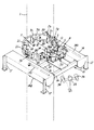
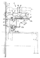
より具体的には、本実施例は、図1,図2に示すように、フロート部14を有する基体部15と、この基体部15に設けられ本実施例を海中金属管支柱1に固定状態に装着するための環状ガイド部7と、この環状ガイド部7に周回移動自在に設けられ海中金属管支柱1の周囲を周回移動する周回移動部8と、この周回移動部8に設けられ海中金属管支柱1に排出孔2を穿孔する穿孔装置3と、この穿孔装置3と同様に周回移動部8に設けられ管体1表面に付着している海生生物等の付着物4を除去する付着物除去装置6とで構成している。   More specifically, in this embodiment, as shown in FIGS. 1 and 2, the base portion 15 having the float portion 14 and the base portion 15 provided in the base portion 15 are fixed to the underwater metal pipe column 1. An annular guide portion 7 for mounting on the annular guide portion 7, an orbiting movement portion 8 that is provided around the annular guide portion 7 so as to be capable of orbiting and moving around the underwater metal pipe column 1, and an underwater metal provided on the orbiting movement portion 8. A drilling device 3 for drilling the discharge hole 2 in the tube strut 1 and an attachment 4 for removing marine organisms and the like attached to the surface of the tube body 1 provided in the orbiting moving portion 8 as in the drilling device 3 It is comprised with the kimono removal apparatus 6. FIG.

更に詳細に説明すると、基体部15は、一対のフロート部14を連結杆16で連結すると共に、フロート部14に載置用脚部17を付設した構成としている。   More specifically, the base portion 15 has a structure in which a pair of float portions 14 are connected by a connecting rod 16 and a mounting leg portion 17 is attached to the float portion 14.

また、この基体部15は、フロート部14によって浮力調整自在な構成としており、具体的には、フロート部14に、外部から空気をフロート部14内に導入する空気導入部14aと、このフロート部14内の空気を外部に導出する空気導出部14bを設け、この空気導入部14a及び空気導出部14bを介してフロート部14内の空気を出し入れしてフロート部14内の空気の充填量を調整してこのフロート部14を浮力調整自在に構成し、このフロート部14の浮力調整によって、本実施例の基体部15を、海中への沈降や海上への浮上を容易にし得る浮力調整自在な構成としている。   In addition, the base portion 15 is configured so that the buoyancy can be adjusted by the float portion 14. Specifically, an air introduction portion 14a for introducing air into the float portion 14 from the outside into the float portion 14, and the float portion. The air lead-out part 14b which leads the air in 14 to the outside is provided, and the amount of air in the float part 14 is adjusted by taking in and out the air in the float part 14 through the air introduction part 14a and the air lead-out part 14b. The float portion 14 is configured to be adjustable in buoyancy, and the buoyancy adjustment in which the base body portion 15 of the present embodiment can be easily submerged in the sea or floated on the sea by adjusting the buoyancy of the float portion 14. It is said.

即ち、本実施例は、管体切断前処理を行うために水中に沈降させる際は、フロート部14内の空気を空気導出部14bから排出してフロート部14の浮力を小さくして沈降し易い状態にし、管体切断前処理が終了し海上に引き上げる際は、空気導入部14aからフロート部14内に空気を導入してフロート部14の浮力を大きくして水中から浮上し易い状態にすることができるように構成している。   That is, in this embodiment, when submerging in water to perform the tube cutting pretreatment, the air in the float unit 14 is discharged from the air outlet 14b to reduce the buoyancy of the float unit 14 and easily settle. When the pipe body pretreatment is finished and pulled up to the sea, air is introduced into the float part 14 from the air introduction part 14a to increase the buoyancy of the float part 14 so that it can easily float from the water. It is configured to be able to.

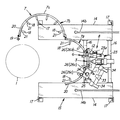
また、環状ガイド部7は、図2,図3に示すように、複数の係止爪部18を有する一対の半円状ガイド部7a,7b、具体的には、基体部15に固定状態に設ける固定半円状ガイド部7aと、この固定半円状ガイド部7aに一端を枢着しこの固定半円状ガイド部7aに開閉回動自在に設けた可動半円状ガイド部7bとで構成している。尚、符号19は、この環状ガイド部7の開動動作を不能にする開動動作ロック機構である。   2 and 3, the annular guide portion 7 is fixed to a pair of semicircular guide portions 7a and 7b having a plurality of locking claws 18; A fixed semicircular guide portion 7a to be provided, and a movable semicircular guide portion 7b provided at one end pivotally attached to the fixed semicircular guide portion 7a and provided to the fixed semicircular guide portion 7a so as to be freely opened and closed. doing. Reference numeral 19 denotes an opening operation locking mechanism that disables the opening operation of the annular guide portion 7.

より具体的には、固定半円状ガイド部7a及び可動半円状ガイド部7bは、図4に示すように、夫々、一対の半円状管体20を上下方向に間隔を置いて並設し、この上下方向に並設した半円状管体20を、これらの間に架設状態に配設した複数の連結リブ21で連設した構成とし、また、この連結リブ21は、海中金属管支柱1に当接し係止する係止爪部18を設けた構成とし、本実施例では、この係止爪部18を一つの連結リブ21に対して二つ、上下方向に並設状態に設けた構成としている。   More specifically, as shown in FIG. 4, the fixed semicircular guide portion 7a and the movable semicircular guide portion 7b are arranged in parallel with a pair of semicircular tube bodies 20 spaced apart from each other in the vertical direction. The semicircular tube bodies 20 arranged side by side in the vertical direction are connected to each other by a plurality of connecting ribs 21 arranged between them, and the connecting ribs 21 are subsea metal pipes. In this embodiment, two locking claws 18 are provided in parallel with one connecting rib 21 in the up-down direction. It has a configuration.

また、係止爪部18は、先端部を尖鋭形状に形成し、連結リブ21に環状ガイド部7の内方に向けて突出状態に設けた構成とし、環状ガイド部7を海中金属管支柱1に取り付けた際、この尖鋭な先端部が海中金属管支柱1表面に付着している海生生物4にくい込み係止するように構成している。   Further, the locking claw portion 18 is formed with a sharp tip at the tip, and is provided on the connecting rib 21 so as to protrude inward of the annular guide portion 7. When attached to the marine organism 4 attached to the surface of the underwater metal pipe column 1, the sharp tip portion is configured to be locked.

更に詳細に説明すると、図5に示すように、係止爪部18には、伸長状態の弾性体22(本実施例ではコイルばねを採用)が設けられており、環状ガイド部7を海中金属管支柱1に取り付けた際、海中金属管支柱1に当接した係止爪部18が弾性体22のバネ付勢に抗して後退し、この係止爪部18の後退により弾性体22が縮退し、この弾性体22が縮退したことでこの弾性体22に伸長付勢が生じ、この弾性体22に生じた伸長付勢が係止爪部18を先端方向に向かって押圧し、これにより、係止爪部18は、海中金属管支柱1に対して押圧係止することとなり、海中金属管支柱1表面やこの海中金属管支柱1表面に付着している海生生物等の付着物4に強固にくい込み係止するように構成している。   More specifically, as shown in FIG. 5, the locking claw portion 18 is provided with an extended elastic body 22 (in this embodiment, a coil spring is used), and the annular guide portion 7 is connected to the underwater metal. When attached to the tube strut 1, the locking claw portion 18 in contact with the underwater metal tube strut 1 moves backward against the spring force of the elastic body 22, and the elastic body 22 is moved back by the retraction of the locking claw portion 18. When the elastic body 22 is degenerated and the elastic body 22 is degenerated, the elastic body 22 is extended and biased, and the elastic body 22 presses the locking claw portion 18 toward the distal end, thereby The locking claw portion 18 is pressed and locked to the underwater metal tube strut 1, and the attached material 4 such as marine organisms attached to the surface of the underwater metal tube strut 1 and the surface of the underwater metal tube strut 1. It is configured so as to be locked in place.

このように、本実施例の環状ガイド部7は、海生生物等の付着物4が付着し表面が凹凸状態の海中金属管支柱1に対しても、全ての係止爪部18が適宜な押圧力で海中金属管支柱1にくい込み係止して本実施例を確実に海中金属管支柱1に固定状態に装着することができるように構成している。   Thus, the annular guide portion 7 of this embodiment has all the locking claws 18 appropriate for the underwater metal tube strut 1 with deposits 4 such as marine organisms attached and the surface being uneven. This embodiment is configured so that the underwater metal tube strut 1 can be fixedly attached to the underwater metal tube strut 1 by being pushed into the underwater metal tube strut 1 with a pressing force.

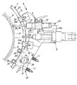
また、周回移動部8は、図6,図7に示すように、穿孔装置3及び付着物除去装置6を配設する作業工具取付部23と、この作業工具取付部23に設けられ駆動部24によって駆動する駆動ローラ10を有する走行部25と、この周回移動部8の環状ガイド部7からの離脱を防止すると共にこの周回移動部8を環状ガイド部7に沿って安定走行させるための複数の従動ローラ26とで構成している。   Further, as shown in FIGS. 6 and 7, the orbiting moving unit 8 is provided with a work tool mounting portion 23 in which the punching device 3 and the deposit removing device 6 are disposed, and a drive unit 24 provided on the work tool mounting portion 23. And a traveling unit 25 having a driving roller 10 driven by the motor, and a plurality of the traveling unit 8 for preventing the separation of the circular moving unit 8 from the annular guide unit 7 and causing the circular moving unit 8 to stably travel along the annular guide unit 7. A driven roller 26 is used.

具体的には、作業装置取付部23は、図8〜図12に示すように、所定間隔(環状ガイド部7の半円状管体20の並設間隔とほぼ同等の間隔)をおいて水平状態に並設した上板部23aと下板部23bとを垂直連結部材23cで連結した構成とすると共に、上板部23aに、環状ガイド部7の固定側半円状ガイド部7a及び可動側半円状ガイド部7bの夫々の上部側の半円状管体20で形成される上部環状ガイド部7cに当接しながら移動する上部従動ローラ26aを設け、下板部23bに、環状ガイド部7の固定側半円状ガイド部7a及び可動側半円状ガイド部7bの夫々の下部側の半円状管体20で形成される下部環状ガイド部7dに当接しながら移動する下部従動ローラ26bを設けて、この上部従動ローラ26aと下部従動ローラ26bとで環状ガイド部7を上下方向から挟持して、この周回移動部8が作業時の振動等で上下方向に移動して(揺動して)環状ガイド部7から離脱しないように構成している。   Specifically, as shown in FIGS. 8 to 12, the work device attachment portion 23 is horizontally arranged at a predetermined interval (interval substantially equal to the interval between the semicircular tubular bodies 20 of the annular guide portion 7). The upper plate portion 23a and the lower plate portion 23b arranged side by side are connected by a vertical connecting member 23c, and the fixed side semicircular guide portion 7a and the movable side of the annular guide portion 7 are connected to the upper plate portion 23a. An upper driven roller 26a that moves while contacting an upper annular guide portion 7c formed by the semicircular tubular body 20 on the upper side of each semicircular guide portion 7b is provided, and the annular guide portion 7 is provided on the lower plate portion 23b. A lower driven roller 26b that moves while abutting on a lower annular guide portion 7d formed by a semicircular tubular body 20 on the lower side of each of the fixed-side semicircular guide portion 7a and the movable-side semicircular guide portion 7b. The upper guide roller 26a and the lower follower roller 26b sandwich the annular guide portion 7 from above and below. Therefore, the orbiting moving portion 8 is configured not to be moved (swinged) in the vertical direction due to vibration during operation or the like so as to be detached from the annular guide portion 7.

また、走行部25は、図13に示すように、駆動部24によって駆動する水平状態に配設した駆動ローラ10と、駆動ローラ10と上部環状ガイド部7cを挟んで対向位置に水平状態に配設される水平従動ローラ26cと、駆動ローラ10に対して水平従動ローラ26cを相対的に接近させる接近付勢を付与する付勢機構11(本実施例ではコイルばね等のばね状弾性体11を使用)とで構成し、このばね状弾性体11によって生じる接近付勢によって駆動ローラ10と水平従動ローラ26cとの間に配設した環状ガイド部7(上部環状ガイド部7c)に対して駆動ローラ10及び水平従動ローラ26cが水平方向から圧接してこの上部環状ガイド部7cを挟持して、この周回移動部8が作業時の振動等で水平方向(前後方向)に移動して(揺動して)環状ガイド部7から離脱しないように構成している。   Further, as shown in FIG. 13, the traveling unit 25 is arranged in a horizontal state at a facing position with the driving roller 10 disposed in a horizontal state driven by the driving unit 24 and the driving roller 10 and the upper annular guide portion 7c interposed therebetween. A horizontal driven roller 26c provided, and a biasing mechanism 11 for applying a biasing force for relatively approaching the horizontal driven roller 26c to the driving roller 10 (in this embodiment, a spring-like elastic body 11 such as a coil spring is provided. And the driving roller with respect to the annular guide portion 7 (upper annular guide portion 7c) disposed between the driving roller 10 and the horizontal driven roller 26c by the approach bias generated by the spring-like elastic body 11. 10 and the horizontal driven roller 26c are pressed from the horizontal direction to sandwich the upper annular guide portion 7c, and the orbiting moving portion 8 is moved (oscillated) in the horizontal direction (front-rear direction) due to vibration during operation. Do not leave the annular guide 7 It is configured as follows.

即ち、本実施例の周回移動部8は、作業装置取付部23に設けた上部従動ローラ26a及び下部従動ローラ26bで環状ガイド部7を上下方向から挟持し、走行部25に設けた駆動ローラ10及び水平従動ローラ26cで環状ガイド部7(上部環状ガイド部7c)を水平方向から挟持して、周回移動部8が環状ガイド部7から離脱しないようにして、この周回移動部8が環状ガイド部7に沿って安定して自走周回移動するように構成している。   That is, the orbiting moving portion 8 of the present embodiment includes the upper driven roller 26a and the lower driven roller 26b provided in the work device mounting portion 23 to sandwich the annular guide portion 7 in the vertical direction, and the driving roller 10 provided in the traveling portion 25. Further, the annular guide portion 7 (upper annular guide portion 7c) is sandwiched from the horizontal direction by the horizontal driven roller 26c so that the orbiting moving portion 8 does not separate from the annular guide portion 7, and the orbiting moving portion 8 becomes the annular guide portion. 7 is configured to stably move around the self-running lap.

尚、付勢機構11は、ばね状弾性体11に限らず、本実施例の作用効果を発揮し得るものであれば適宜採用するものとする。   The urging mechanism 11 is not limited to the spring-like elastic body 11 and may be appropriately employed as long as it can exert the effects of the present embodiment.

また、本実施例の周回移動部8は、この駆動ローラ10をばね状弾性体11により環状ガイド部7に圧接させる構成としたことで、付着物除去装置6の除去工具部12に過負荷が生じようとした際には、付勢力若しくは押圧力に抗して駆動ローラ10が逃動しこの駆動ローラ10がスリップすることで、この周回移動部8の周回移動が停止若しくは減速するように構成している。   Further, the orbiting moving unit 8 of the present embodiment is configured such that the drive roller 10 is pressed against the annular guide portion 7 by the spring-like elastic body 11, so that an overload is applied to the removing tool portion 12 of the deposit removing device 6. When it is going to occur, the drive roller 10 escapes against the urging force or pressing force, and the drive roller 10 slips, so that the circular movement of the circular moving unit 8 is stopped or decelerated. doing.

即ち、例えば、周回移動中にこの周回移動部8に設けた付着物除去装置6が海中金属管支柱1の付着物4に引っ掛かり、この周回移動部8の周回移動しようとする力によって付着物除去装置6の除去工具部12に、この除去工具部12が破損してしまいそうな大きな過負荷が生じようとした際に、移動を抑制されたことで駆動ローラ10の周回移動方向に移動しようとする力が外方に向かって作用し、この外方に作用する力がばね状弾性体11を縮退させ、このばね状弾性体11の縮退により駆動ローラ10及び水平従動ローラ26cの環状ガイド部7(上部環状ガイド部7c)に対する圧接力が弱まり、この圧接力が弱まったことで駆動ローラ10がスリップして周回移動部8が周回移動方向へ移動しようとする力が低下して、この周回移動部8の周回移動が停止若しくは減速することで、付着物4に引っ掛かった付着物除去装置6の除去工具部12に、この除去工具部12が破損してしまうような大きな過負荷が生じないように構成している。   That is, for example, the deposit removing device 6 provided in the orbiting moving section 8 is caught by the deposit 4 of the underwater metal pipe column 1 during the orbiting movement, and the adhering substance removal is performed by the force of the orbiting moving section 8 trying to move around. When a large overload is generated in the removal tool portion 12 of the apparatus 6 so that the removal tool portion 12 is likely to be damaged, the movement is restrained so that the drive roller 10 moves in the circumferential movement direction. Force acting outwardly, the outwardly acting force causes the spring-like elastic body 11 to contract, and the spring-like elastic body 11 contracts to cause the annular guide portion 7 of the driving roller 10 and the horizontal driven roller 26c. The pressure contact force with respect to the (upper annular guide portion 7c) is weakened, and since the pressure contact force is weakened, the drive roller 10 slips and the force that the orbiting moving unit 8 tries to move in the orbiting movement direction is reduced. Circulation movement of part 8 stops Alternatively, by decelerating, the removal tool portion 12 of the deposit removal device 6 caught on the deposit 4 is configured not to have a large overload that would damage the removal tool portion 12.

尚、本実施例の周回移動部8は、遠隔操作可能な構成とし、作業現場から離れた場所、例えば、海上に停泊する作業船13上から遠隔操作によって作動することができるように構成している。   It should be noted that the orbital moving unit 8 of the present embodiment is configured to be remotely operable, and configured to be able to be operated by remote operation from a place away from the work site, for example, on the work ship 13 anchored at sea. Yes.

また、穿孔装置3及び付着物除去装置6は、一般的に使用されるものを用いており、本実施例では、図6,図7に示すように、穿孔装置3は一般的なドリル工具を用い、また、付着物除去装置6は除去工具部12としてバイブレーションスクレーパ工具12(エア駆動式打撃素地調整工具)を用いた構成とし、これらを上述した周回移動部8の作業装置取付部23に左右方向に並設し、夫々、移動機構によって進退移動自在設けると共に、遠隔操作によって作動可能な構成としている。   Further, the drilling device 3 and the deposit removing device 6 are those commonly used. In this embodiment, as shown in FIGS. 6 and 7, the drilling device 3 uses a general drill tool. In addition, the deposit removing device 6 is configured to use a vibration scraper tool 12 (air-driven striking ground adjusting tool) as the removing tool portion 12, and these are left and right to the working device mounting portion 23 of the orbiting moving portion 8 described above. They are arranged side by side in a direction, and each of them can be moved forward and backward by a moving mechanism, and can be operated by remote control.

尚、本実施例では、穿孔装置3の周回移動方向前方側に付着物除去装置6を並設状態に設けた構成とし、具体的には、前方に位置する付着物除去装置6で、穿孔装置3が穿孔作業する位置の海中金属管支柱1表面に付着している海生生物等の付着物4を除去して穿孔用表面付着物除去部9を形成し、この穿孔用表面付着物除去部9を形成し終えて付着物除去装置6が作業を停止した際、穿孔装置3がこの付着物除去装置6によって形成された穿孔用表面付着物除去部9に位置するように構成している。   In the present embodiment, the deposit removing device 6 is provided in parallel with the drilling device 3 on the front side in the circumferential movement direction. Specifically, the deposit removing device 6 located in the front includes the punching device. The surface deposit removing part 9 for drilling is formed by removing the deposits 4 such as marine organisms adhering to the surface of the underwater metal tube strut 1 at the position where 3 is drilled, and this surface deposit removing part 9 for drilling is formed. When the deposit removing device 6 stops working after the formation of the deposit 9, the punching device 3 is positioned on the surface deposit removing portion 9 for drilling formed by the deposit removing device 6.

また、穿孔装置3及び付着物除去装置6を進退移動させる移動機構は、図8〜図11及び図14に示すように、スライドガイド部27と、このスライドガイド部27にスライド移動自在に設けた取付け台28とで構成し、本実施例の穿孔装置3及び付着物除去装置6は、この取付け台28のスライド移動により、周回移動部8の作業装置取付部23にスライド移動自在に設けた構成としている。   Further, as shown in FIGS. 8 to 11 and 14, the moving mechanism for moving the punching device 3 and the deposit removing device 6 back and forth is provided so as to be slidable on the slide guide portion 27 and the slide guide portion 27. The piercing device 3 and the deposit removing device 6 of this embodiment are slidably provided on the work device mounting portion 23 of the orbiting moving portion 8 by sliding movement of the mounting table 28. It is said.

具体的には、図14に示すように、左右に並設した二台の取付け台28の間に、この取付け台28を移動させる取付け台駆動用歯車29を配設し、この取付け台駆動用歯車29(ピニオン)と夫々の取付け台28に設けた直線歯車30(ラック)とを係合させ、取付け台駆動用歯車29の回転により取付け台28をスライドガイド部27に沿って前後方向にスライド移動させる構成とし、また、本実施例では、上述したように二台の取付け台28の間に設けた一つの取付け台駆動用歯車29で両方の取付け台28を移動させる構成としたので、取付け台駆動用歯車29を一方向に回転させると、一方の取付け台28は前進移動し、他方の取付け台28は後退移動する構成としている。   Specifically, as shown in FIG. 14, a mounting drive gear 29 for moving the mounting base 28 is disposed between two mounting bases 28 arranged side by side, and this mounting base driving gear is provided. The gear 29 (pinion) and the linear gear 30 (rack) provided on each mounting base 28 are engaged, and the mounting base 28 is slid back and forth along the slide guide portion 27 by the rotation of the mounting base driving gear 29. In this embodiment, as described above, both the mounting bases 28 are moved by one mounting base driving gear 29 provided between the two mounting bases 28 as described above. When the table driving gear 29 is rotated in one direction, one mounting table 28 moves forward, and the other mounting table 28 moves backward.

即ち、管体切断前処理においては、穿孔装置3を用いる穿孔作業と付着物除去装置6を用いる付着物除去作業との双方を同時に作業しないので、例えば、穿孔作業を行うために穿孔装置3を前進させると、付着物除去装置6は後方に後退して待機状態となり、付着物除去作業を行うために付着物除去装置6を前進させると、前方に位置していた穿孔装置3は後方に後退して待機状態になり、夫々の作業の妨げとならないように構成している。   That is, in the tube body cutting pretreatment, both the drilling operation using the punching device 3 and the deposit removing operation using the deposit removing device 6 are not performed at the same time. When it moves forward, the deposit removing device 6 moves backward to enter a standby state, and when the deposit removing device 6 is moved forward to perform the deposit removing operation, the punching device 3 located in the front moves backward. Thus, it is configured so as to be in a standby state and not hinder each work.

また、付着物除去装置6は、取付け台28に対して、回動自在に設けて除去工具部12の先端部の海中金属管支柱1表面への進入角度(当接角度)を角度調整自在に設けると共に、上下方向に移動自在に設けて高さ位置調整自在に設けた構成としている。   Further, the deposit removing device 6 is provided so as to be rotatable with respect to the mounting base 28 so that the angle of entry (contact angle) of the tip of the removal tool portion 12 to the surface of the underwater metal pipe column 1 can be adjusted. In addition, it is configured to be movable in the vertical direction and to be adjustable in height position.

具体的には、図12に示すように、取付け台28に付着物除去装置6を支持する支持部31を立設し、この支持部31にスライドガイド孔32を設けて、付着物除去装置6をこのスライドガイド孔32に沿ってスライド移動自在に設けた構成としている。   Specifically, as shown in FIG. 12, a support portion 31 that supports the deposit removing device 6 is erected on the mounting base 28, and a slide guide hole 32 is provided in the support portion 31, so that the deposit removing device 6. Is configured to be slidable along the slide guide hole 32.

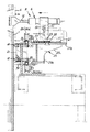
また、穿孔装置3及び付着物除去装置6を遠隔操作可能な構成としたので、本実施例を用いた管体切断前処理の穿孔作業及び付着物除去作業は、図15に示すように、海上に停泊している作業船13上から行われる。その際、作業状況を確認しながら作業できるよう作業状況を映す水中カメラ33と、この作業箇所を照らす水中ライト34を周回移動部8に設けている。   Further, since the drilling device 3 and the deposit removing device 6 are configured to be remotely operable, the drilling operation and the deposit removing operation for the tube cutting pretreatment using this embodiment are performed at sea as shown in FIG. It is carried out from the work boat 13 moored at. At this time, an underwater camera 33 that reflects the work status and an underwater light 34 that illuminates the work location are provided in the orbiting movement unit 8 so that the work status can be checked while checking the work status.

尚、図15中の符号35,36は、穿孔装置3及び付着物除去装置6を作動させるための油圧ポンプとエアーコンプレッサである。   In addition, the codes | symbols 35 and 36 in FIG. 15 are the hydraulic pump and air compressor for operating the punching apparatus 3 and the deposit | attachment removal apparatus 6. FIG.

また、本実施例では、穿孔装置3と付着物除去装置6との二種類の作業装置(作業工具)を設けた構成としたが、本実施例の構成に加えて、海中金属管支柱1を切断する切断装置を設けた構成としても良い。   In the present embodiment, two types of work devices (work tools) including the drilling device 3 and the deposit removing device 6 are provided. However, in addition to the configuration of the present embodiment, the underwater metal pipe column 1 is provided. It is good also as a structure which provided the cutting device which cut | disconnects.

この切断装置を設ける場合は、周回移動部8の周回移動方向の前側に付着物除去装置6を設け、後側に切断装置を設けた構成とすることが好ましく(穿孔装置3は切断装置の前後いずれでも良い)、これにより、付着物除去装置6で海中金属管支柱1表面に付着している海生生物等の付着物4を除去する付着物除去作業を進めながら、海中金属管支柱1を切断する切断作業を行うことができる。   In the case of providing this cutting device, it is preferable that the deposit removing device 6 is provided on the front side of the orbiting movement portion 8 and the cutting device is provided on the rear side. In this way, the submerged metal pipe strut 1 can be removed while proceeding with the fouling removal work for removing the adhering substances 4 such as marine organisms adhering to the surface of the submarine metal pipe strut 1 with the deposit removing device 6. A cutting operation for cutting can be performed.

以上のように構成した本実施例の作用・効果を以下に説明する。   The operation and effect of the present embodiment configured as described above will be described below.

本実施例を用いて海中金属管支柱1の管体切断前処理を行う際、先ず、海上に載置した本実施例をフロート部14の浮力を調整して所定の作業位置まで沈降させ、作業位置にて環状ガイド部7を開動操作し、海中金属管支柱1の周囲に、この海中金属管支柱1を囲むようにして取り付けて、本実施例を海中金属管支柱1に装着する。   When performing the tube cutting pretreatment of the underwater metal pipe support column 1 using the present embodiment, first, the present embodiment placed on the sea is set to a predetermined working position by adjusting the buoyancy of the float portion 14 and working. The annular guide portion 7 is operated to open at the position, and is attached to the underwater metal pipe column 1 so as to surround the underwater metal tube column 1, and this embodiment is attached to the underwater metal tube column 1.

この際、環状ガイド部7に設けた複数の係止爪部18が、海中金属管支柱1表面やこの海中金属管支柱1表面に付着している海生生物等の付着物4にくい込み係止し、本実施例を海中金属管支柱1に強固に固定することができる。   At this time, the plurality of locking claws 18 provided on the annular guide portion 7 are difficult to lock in the deposits 4 such as marine organisms attached to the surface of the underwater metal pipe column 1 and the surface of the underwater metal tube column 1. In addition, this embodiment can be firmly fixed to the underwater metal pipe column 1.

本実施例を海中金属管支柱1に装着した後、作業者は海上の作業船13に戻り、周回移動部8及び穿孔装置3、付着物除去装置6を遠隔操作して管体切断前処理である穿孔作業と付着物除去作業を行う。   After mounting this embodiment on the underwater metal pipe column 1, the operator returns to the offshore work boat 13 and remotely operates the orbiting moving unit 8, the drilling device 3 and the deposit removing device 6 to perform the tube cutting pretreatment. Do some drilling and deposit removal.

具体的には、先ず、排出孔2を穿孔する位置の海中金属管支柱1表面に付着している海生生物等の付着物4を除去するために、付着物除去装置6を作動させながら周回移動部8を周回方向に移動させ、海中金属管支柱1表面に帯状に付着物4を除去した穿孔用表面付着物除去部9を形成し、この穿孔用表面付着物除去部9を形成し終えた状態で、取付け台駆動用歯車29を駆動させて付着物除去装置6を後退させて退避位置に移動させると、この付着物除去装置6の退避移動に伴って穿孔装置3が前進し作業位置に移動し、この作業位置に移動した穿孔装置3を作動させて穿孔用表面付着物除去部9に排出孔2を穿孔する穿孔作業を作業船13で遠隔操作にて行う。   Specifically, first, in order to remove the adhering material 4 such as marine organisms adhering to the surface of the underwater metal pipe column 1 at the position where the discharge hole 2 is drilled, the adhering material removing device 6 is operated while rotating. The moving part 8 is moved in the circumferential direction, and the surface adhering substance removing part 9 for drilling is formed on the surface of the underwater metal pipe column 1 by removing the adhering substance 4 in a band shape. In this state, when the attachment driving gear 29 is driven to move the deposit removing device 6 backward and move to the retracted position, the punching device 3 moves forward with the retracting movement of the deposit removing device 6 and moves to the working position. Then, the drilling device 3 moved to this working position is operated, and the drilling work for drilling the discharge hole 2 in the drilling surface deposit removing part 9 is performed remotely on the work ship 13.

排出孔2の穿孔作業が終了したら、作業者は一端、水中に潜り、付着物除去装置6を可動に移動させて付着物除去装置6の除去工具部12(バイブレーションスクレーパ工具12)先端を切断位置に合わせる。   When the drilling operation of the discharge hole 2 is completed, the operator dives into the water at one end, moves the deposit removal device 6 movably, and cuts the tip of the removal tool portion 12 (vibration scraper tool 12) of the deposit removal device 6. To match.

位置合わせを終えたら、作業者は、再度、作業現場から離れ、作業船13で付着物除去装置6を作動させながら周回移動部8を海中金属管支柱1に沿って周回移動させて、この海中金属管支柱1の切断位置に付着している海生生物等の付着物4を除去して切断用付着物除去部5を形成し管体切断前処理が終了し、この本実施例を用いた管体切断前処理により、海中金属管支柱1には、図16,図17に示すように、穿孔用表面付着物除去部9に排出孔2が穿孔され、また、この排出孔2の下方位置に切断位置となる切断用付着物除去部5が形成される。   When the alignment is completed, the operator leaves the work site again and moves the orbiting moving part 8 along the underwater metal pipe column 1 while operating the deposit removing device 6 on the work ship 13. The attached matter 4 such as marine organisms adhering to the cutting position of the metal tube support 1 is removed to form the attached matter removing portion 5 for cutting, and the tube cutting pretreatment is completed, and this embodiment is used. As shown in FIG. 16 and FIG. 17, a discharge hole 2 is drilled in the perforated surface deposit removing portion 9 in the submerged metal tube column 1 by the pipe body cutting pretreatment, and a position below the discharge hole 2 The cutting deposit removing portion 5 serving as the cutting position is formed.

このように、本実施例は、環状ガイド部7を海中金属管支柱1に装着することで、穿孔装置3及び付着物除去装置6を、環状ガイド部7を介して海中金属管支柱1に装着し、これを遠隔操作によって海中金属管支柱1の周方向に移動させながら穿孔作業や付着物除去作業を行うことができるので、従来のように、作業者が作業工具を手持して作業をする必要が無いので、作業者は海中で作業反力を得るという非常に厄介な作業を強いられることが無くなり、また、作業者が作業反力を得るためにコストを掛けて足場を設置する必要も無くなるので、海中金属管支柱1を切断する際の前処理である穿孔作業及び付着物除去作業において、これらの作業の作業者への負担を軽減し、効率良く且つ低コストで行うことができる実用性に優れた画期的な管体切断前処理装置となる。   As described above, in this embodiment, the annular guide portion 7 is attached to the underwater metal pipe column 1 so that the drilling device 3 and the deposit removing device 6 are attached to the underwater metal tube column 1 via the annular guide portion 7. In addition, since the drilling work and the deposit removal work can be performed while moving this in the circumferential direction of the underwater metal pipe column 1 by remote operation, the worker holds the work tool as before and works. Since there is no need, the operator will not be forced to carry out a very troublesome task of obtaining a reaction force in the sea, and the operator will need to install a scaffolding at a cost to obtain the reaction force Since there is no need, it is possible to reduce the burden on the operator of drilling work and deposit removal work, which are pre-treatments when cutting the underwater metal pipe column 1, and to perform the work efficiently and at low cost. Excellent groundbreaking A tube before cutting processing device.

また、この海底地盤に根入れされた海中金属管支柱1は、内部に海底地盤中から漏出した天然ガス等の可燃性ガスが溜まっている可能性があり、この可燃性ガスが溜まっている状態の海中金属管支柱1を穿孔装置3で穿孔すると、穿孔時に生じた火花が可燃性ガスに引火し爆発する恐れがあるが、この点、本実施例は、穿孔装置3を遠隔操作により穿孔作動自在に設けた構成としたので、穿孔作業時は、作業者は穿孔現場にいなくても良く、穿孔現場から離れた安全な場所、即ち、海上に停泊している作業船13上で穿孔作業を行うこととなるので、安全性にも優れた画期的な管体切断前処理装置となる。   In addition, the underwater metal pipe strut 1 embedded in the seabed ground may contain flammable gas such as natural gas leaked from the seabed ground, and the state where the flammable gas is accumulated. If the underwater metal pipe column 1 is drilled with the drilling device 3, the spark generated during drilling may ignite the combustible gas and explode. In this respect, in this embodiment, the drilling device 3 is drilled by remote control. Because it is configured freely, the operator does not have to be at the drilling site during drilling work, and the drilling work is performed on a safe place away from the drilling site, that is, on the work ship 13 anchored at sea. Therefore, it becomes an epoch-making pretreatment apparatus for cutting a tube excellent in safety.

尚、本発明は、本実施例に限られるものではなく、各構成要件の具体的構成は適宜設計し得るものである。   Note that the present invention is not limited to this embodiment, and the specific configuration of each component can be designed as appropriate.

1 管体,海中金属管支柱
2 排出孔
3 穿孔装置
4 付着物
5 切断用付着物除去部
6 付着物除去装置
7 環状ガイド部
8 周回移動部
9 穿孔用表面付着物除去部
10 駆動ローラ
11 付勢機構
12 除去工具部,バイブレーションスクレーパ工具
DESCRIPTION OF SYMBOLS 1 Tube, Underwater metal pipe support | pillar 2 Discharge hole 3 Punching device 4 Deposit 5 Adherent removal part for cutting 6 Deposit removing device 7 Annular guide part 8 Circumferential movement part 9 Surface deposit removal part for drill
10 Drive roller
11 Energizing mechanism
12 Removal tool, vibration scraper tool

Claims (7)

管体を切断する前にこの管体内の可燃性ガスを排出するための排出孔を穿孔する穿孔装置と、前記管体の切断位置表面に付着した付着物を除去して切断用付着物除去部を形成する付着物除去装置とを備えた管体切断前処理装置であって、前記管体を囲むようにこの管体周囲に着脱自在に取り付ける環状ガイド部に、この環状ガイド部に沿って周回移動する周回移動部を設け、この周回移動部に前記穿孔装置と前記付着物除去装置とを設け、少なくとも前記穿孔装置を遠隔操作により穿孔作動自在に設けたことを特徴とする管体切断前処理装置。   A perforation device for perforating a discharge hole for exhausting flammable gas in the pipe before cutting the pipe, and an adhering matter removing unit for removing the adhering matter adhering to the cutting position surface of the pipe An apparatus for pre-cutting a tube body including a deposit removing device for forming a tube, and an annular guide portion detachably attached to the periphery of the tube body so as to surround the tube body. A tube cutting pretreatment characterized in that a revolving movement unit is provided, the perforation device and the deposit removal device are provided in the revolving movement unit, and at least the perforation device is provided so as to be perforated by remote control. apparatus. 前記穿孔装置により穿孔した前記排出孔よりも前記管体の長さ方向の一方側若しくは他方側に前記付着物除去装置を位置させ、この付着物除去装置を前記環状ガイド部に沿って前記周回移動部を介して周回移動させて前記管体表面に付着している付着物を除去して前記切断用付着物除去部を形成するように構成したことを特徴とする請求項1記載の管体切断前処理装置。   The deposit removing device is positioned on one side or the other side in the length direction of the tubular body from the discharge hole drilled by the punching device, and the deposit removing device is moved around the annular guide portion. The tube cutting device according to claim 1, wherein the cutting material removing portion is formed by removing the adhering material adhering to the surface of the tubular body by moving around through the portion. Pre-processing device. 前記穿孔装置の前記周回移動方向に並設状態に前記付着物除去装置を設け、この付着物除去装置を前記管体の長さ方向に移動自在に設けて、前記付着物除去装置により前記管体表面に付着している付着物を除去して穿孔用表面付着物除去部を形成し、この穿孔用表面付着物除去部に前記穿孔装置により前記排出孔を穿孔すると共に、前記付着物除去装置を前記管体の長さ方向に移動して前記排出孔より前記管体の長さ方向の一方側若しくは他方側に位置させて周回移動させることで、少なくとも前記管体表面に付着している付着物を半周以上除去して前記切断用付着物除去部を形成するように構成したことを特徴とする請求項1,2のいずれか1項に記載の管体切断前処理装置。   The deposit removing device is provided in parallel with the circumferential movement direction of the perforating device, and the deposit removing device is movably provided in the length direction of the tubular body. A deposit adhered to the surface is removed to form a surface deposit removing portion for punching, and the discharge hole is drilled by the punching device in the surface deposit removing portion for drilling. Deposits adhered to at least the surface of the tube body by moving in the length direction of the tube body and moving around the discharge hole from one side or the other side in the length direction of the tube body The tube cutting pretreatment device according to any one of claims 1 and 2, characterized in that the cutting deposit removing part is formed by removing at least half a circle. 前記周回移動部は、駆動ローラを付勢機構による付勢力若しくは押圧機構による押圧力により前記環状ガイド部に圧接して、この駆動ローラの駆動制御により前記環状ガイド部に沿って自走周回移動する若しくは周回移動補助力が生じるように構成し、前記付着物除去装置の除去工具部に過負荷が生じようとした際には、前記付勢力若しくは前記押圧力に抗して前記駆動ローラが逃動しこの駆動ローラがスリップすることで、前記周回移動部の周回移動が停止若しくは減速するように構成したことを特徴とする請求項1〜3のいずれか1項に記載の管体切断前処理装置。   The orbiting moving portion presses the driving roller against the annular guide portion by an urging force by an urging mechanism or a pressing force by a pressing mechanism, and moves around the annular guide portion by driving control of the driving roller. Alternatively, the driving roller is configured to generate an orbital movement assisting force, and when the overload is generated in the removing tool portion of the deposit removing device, the driving roller is released against the biasing force or the pressing force. The tube cutting pretreatment device according to any one of claims 1 to 3, wherein the driving roller slips to stop or decelerate the circular movement of the circular moving unit. . 前記付着物除去装置は、所定角度で前記管体表面に圧接すると共に打撃振動して前記管体表面に付着している付着物を剥離除去するバイブレーションスクレーパ工具を前記除去工具部として採用したことを特徴とする請求項1〜4のいずれか1項に記載の管体切断前処理装置。   The adhering matter removing apparatus adopts a vibration scraper tool that presses against the tube surface at a predetermined angle and strikes and vibrates to remove the adhering matter adhering to the tube surface as the removing tool portion. The tube cutting pretreatment device according to any one of claims 1 to 4, wherein the tube cutting pretreatment device is characterized in that: 前記周回移動部に、前記穿孔装置及び前記付着物除去装置を設けると共に、前記付着物除去装置により前記管体に形成した前記切断用付着物除去部を切断位置として切断する切断装置をも設けたことを特徴とする請求項1〜5のいずれか1項に記載の管体切断前処理装置。   In addition to providing the perforating device and the deposit removing device in the circular moving portion, a cutting device for cutting the cutting deposit removing portion formed on the tubular body by the deposit removing device as a cutting position is also provided. The tube cutting pretreatment device according to any one of claims 1 to 5, wherein 前記管体は、下端が海底地盤に埋設された海中金属管支柱であり、この海中金属管支柱を高熱を伴う切断装置で切断する際の前処理として、この切断装置の切断位置の上方側に前記海中金属管支柱内の可燃性ガスを排出するための前記排出孔を穿孔するように前記穿孔装置を構成し、この排出孔よりも下方側の前記管体表面に付着している付着物である海生生物を除去して前記切断用付着物除去部を形成するように前記付着物除去装置を構成したことを特徴とする請求項1〜6のいずれか1項に記載の管体切断前処理装置。   The pipe body is a submarine metal pipe strut whose lower end is buried in the seabed ground, and as a pretreatment when cutting this submarine metal pipe strut with a cutting device with high heat, above the cutting position of this cutting device. The perforating apparatus is configured to perforate the discharge hole for discharging the combustible gas in the submarine metal pipe column, and is attached to the tube body surface below the discharge hole. The tube attachment cutting device according to any one of claims 1 to 6, wherein the deposit removing device is configured to remove a marine organism to form the cutting deposit removing portion. Processing equipment.
JP2012271375A 2012-12-12 2012-12-12 Tube cutting pretreatment device Expired - Fee Related JP6031345B2 (en)

Priority Applications (1)

Application Number Priority Date Filing Date Title
JP2012271375A JP6031345B2 (en) 2012-12-12 2012-12-12 Tube cutting pretreatment device

Applications Claiming Priority (1)

Application Number Priority Date Filing Date Title
JP2012271375A JP6031345B2 (en) 2012-12-12 2012-12-12 Tube cutting pretreatment device

Publications (2)

Publication Number Publication Date
JP2014114663A true JP2014114663A (en) 2014-06-26
JP6031345B2 JP6031345B2 (en) 2016-11-24

Family

ID=51170960

Family Applications (1)

Application Number Title Priority Date Filing Date
JP2012271375A Expired - Fee Related JP6031345B2 (en) 2012-12-12 2012-12-12 Tube cutting pretreatment device

Country Status (1)

Country Link
JP (1) JP6031345B2 (en)

Cited By (1)

* Cited by examiner, † Cited by third party
Publication number Priority date Publication date Assignee Title
JP6010655B1 (en) * 2015-04-27 2016-10-19 新潟潜水興業株式会社 Underwater cutting device

Citations (3)

* Cited by examiner, † Cited by third party
Publication number Priority date Publication date Assignee Title
JPS5386660A (en) * 1977-01-11 1978-07-31 Kogyo Gijutsuin Oxygen arc cutting apparatus for steel tube
JPS60148925A (en) * 1984-01-13 1985-08-06 Nippon Steel Corp Steel pipe cutting device
JPH0233835U (en) * 1988-08-24 1990-03-02

Patent Citations (3)

* Cited by examiner, † Cited by third party
Publication number Priority date Publication date Assignee Title
JPS5386660A (en) * 1977-01-11 1978-07-31 Kogyo Gijutsuin Oxygen arc cutting apparatus for steel tube
JPS60148925A (en) * 1984-01-13 1985-08-06 Nippon Steel Corp Steel pipe cutting device
JPH0233835U (en) * 1988-08-24 1990-03-02

Cited By (1)

* Cited by examiner, † Cited by third party
Publication number Priority date Publication date Assignee Title
JP6010655B1 (en) * 2015-04-27 2016-10-19 新潟潜水興業株式会社 Underwater cutting device

Also Published As

Publication number Publication date
JP6031345B2 (en) 2016-11-24

Similar Documents

Publication Publication Date Title
US8276577B2 (en) Boom mounted saw
EP1592907B1 (en) Method for cutting and removing underwater pipelines and apparatus for implementing this method
US4856938A (en) Method of and arrangement for separating tubular foundation piles under water
EP3353048B1 (en) Moving tools on offshore structures with a walking carriage
WO2002075059A1 (en) Method and apparatus for cutting underwater structures
EP2845793A1 (en) Apparatus and method for deploying an object to a sea floor
KR101669588B1 (en) Hole Drilling Machine for Under Water and Removal Equipment for Sunken Ship's Remained Oil
KR101484303B1 (en) Underwater drilling arrangement and method for introducing a tubular foundation element into the bed of a body of water
CN110863491A (en) Device and method for blowing mud of abandoned submarine pile pipe downwards and cutting mud
US20150290727A1 (en) Method and apparatus for cutting underwater structures
JP6031345B2 (en) Tube cutting pretreatment device
NO343423B1 (en) Mobile cutting tool and method for cutting a subsea tubular structure
EP0087971B1 (en) Apparatus for removing covering material from underwater pipelines
US20040216570A1 (en) Underwater pile cutting apparatus and method of use
JP5268712B2 (en) Seismic retrofitting method and equipment for manhole and sewer pipe connections
JP6010655B1 (en) Underwater cutting device
JP2006249694A (en) Cleaning device of open caisson cutting edge
JP2013087515A5 (en)
GB2529908A (en) Apparatus and method for localised surface cleaning
JP2024047465A (en) Cutting device and method for cutting and removing rod-shaped members
Brandon et al. Abrasive water-jet and diamond wire-cutting technologies used in the removal of marine structures
KR101547294B1 (en) Grinding device for metal plate
JP4349538B2 (en) Steel cutting device
US11872608B2 (en) Method of removing sludge from a drain pipe
JP4009037B2 (en) Cutting method and apparatus for inner wall surface of concrete pipe

Legal Events

Date Code Title Description
A621 Written request for application examination

Free format text: JAPANESE INTERMEDIATE CODE: A621

Effective date: 20151214

A711 Notification of change in applicant

Free format text: JAPANESE INTERMEDIATE CODE: A711

Effective date: 20160229

A521 Request for written amendment filed

Free format text: JAPANESE INTERMEDIATE CODE: A821

Effective date: 20160229

A977 Report on retrieval

Free format text: JAPANESE INTERMEDIATE CODE: A971007

Effective date: 20160914

TRDD Decision of grant or rejection written
A01 Written decision to grant a patent or to grant a registration (utility model)

Free format text: JAPANESE INTERMEDIATE CODE: A01

Effective date: 20160926

A61 First payment of annual fees (during grant procedure)

Free format text: JAPANESE INTERMEDIATE CODE: A61

Effective date: 20161024

R150 Certificate of patent or registration of utility model

Ref document number: 6031345

Country of ref document: JP

Free format text: JAPANESE INTERMEDIATE CODE: R150

R250 Receipt of annual fees

Free format text: JAPANESE INTERMEDIATE CODE: R250

R250 Receipt of annual fees

Free format text: JAPANESE INTERMEDIATE CODE: R250

LAPS Cancellation because of no payment of annual fees