JP2014111165A - Razor cartridge pivot axis - Google Patents
Razor cartridge pivot axis Download PDFInfo
- Publication number
- JP2014111165A JP2014111165A JP2014018565A JP2014018565A JP2014111165A JP 2014111165 A JP2014111165 A JP 2014111165A JP 2014018565 A JP2014018565 A JP 2014018565A JP 2014018565 A JP2014018565 A JP 2014018565A JP 2014111165 A JP2014111165 A JP 2014111165A
- Authority
- JP
- Japan
- Prior art keywords
- blade
- frame
- razor cartridge
- pivot
- axis
- Prior art date
- Legal status (The legal status is an assumption and is not a legal conclusion. Google has not performed a legal analysis and makes no representation as to the accuracy of the status listed.)
- Pending
Links
Images


Classifications
-
- B—PERFORMING OPERATIONS; TRANSPORTING
- B26—HAND CUTTING TOOLS; CUTTING; SEVERING
- B26B—HAND-HELD CUTTING TOOLS NOT OTHERWISE PROVIDED FOR
- B26B21/00—Razors of the open or knife type; Safety razors or other shaving implements of the planing type; Hair-trimming devices involving a razor-blade; Equipment therefor
- B26B21/08—Razors of the open or knife type; Safety razors or other shaving implements of the planing type; Hair-trimming devices involving a razor-blade; Equipment therefor involving changeable blades
- B26B21/14—Safety razors with one or more blades arranged transversely to the handle
- B26B21/22—Safety razors with one or more blades arranged transversely to the handle involving several blades to be used simultaneously
- B26B21/222—Safety razors with one or more blades arranged transversely to the handle involving several blades to be used simultaneously with the blades moulded into, or attached to, a changeable unit
- B26B21/225—Safety razors with one or more blades arranged transversely to the handle involving several blades to be used simultaneously with the blades moulded into, or attached to, a changeable unit the changeable unit being resiliently mounted on the handle
-
- B—PERFORMING OPERATIONS; TRANSPORTING
- B26—HAND CUTTING TOOLS; CUTTING; SEVERING
- B26B—HAND-HELD CUTTING TOOLS NOT OTHERWISE PROVIDED FOR
- B26B21/00—Razors of the open or knife type; Safety razors or other shaving implements of the planing type; Hair-trimming devices involving a razor-blade; Equipment therefor
- B26B21/08—Razors of the open or knife type; Safety razors or other shaving implements of the planing type; Hair-trimming devices involving a razor-blade; Equipment therefor involving changeable blades
- B26B21/14—Safety razors with one or more blades arranged transversely to the handle
- B26B21/24—Safety razors with one or more blades arranged transversely to the handle of the magazine type; of the injector type
-
- B—PERFORMING OPERATIONS; TRANSPORTING
- B26—HAND CUTTING TOOLS; CUTTING; SEVERING
- B26B—HAND-HELD CUTTING TOOLS NOT OTHERWISE PROVIDED FOR
- B26B21/00—Razors of the open or knife type; Safety razors or other shaving implements of the planing type; Hair-trimming devices involving a razor-blade; Equipment therefor
- B26B21/40—Details or accessories
- B26B21/4012—Housing details, e.g. for cartridges
- B26B21/4031—Housing details, e.g. for cartridges characterised by special geometric shaving parameters, e.g. blade span or exposure
-
- B—PERFORMING OPERATIONS; TRANSPORTING
- B26—HAND CUTTING TOOLS; CUTTING; SEVERING
- B26B—HAND-HELD CUTTING TOOLS NOT OTHERWISE PROVIDED FOR
- B26B21/00—Razors of the open or knife type; Safety razors or other shaving implements of the planing type; Hair-trimming devices involving a razor-blade; Equipment therefor
- B26B21/54—Razor-blades
-
- Y—GENERAL TAGGING OF NEW TECHNOLOGICAL DEVELOPMENTS; GENERAL TAGGING OF CROSS-SECTIONAL TECHNOLOGIES SPANNING OVER SEVERAL SECTIONS OF THE IPC; TECHNICAL SUBJECTS COVERED BY FORMER USPC CROSS-REFERENCE ART COLLECTIONS [XRACs] AND DIGESTS
- Y10—TECHNICAL SUBJECTS COVERED BY FORMER USPC
- Y10T—TECHNICAL SUBJECTS COVERED BY FORMER US CLASSIFICATION
- Y10T29/00—Metal working
- Y10T29/49—Method of mechanical manufacture
- Y10T29/49826—Assembling or joining
- Y10T29/49863—Assembling or joining with prestressing of part
- Y10T29/49876—Assembling or joining with prestressing of part by snap fit
-
- Y—GENERAL TAGGING OF NEW TECHNOLOGICAL DEVELOPMENTS; GENERAL TAGGING OF CROSS-SECTIONAL TECHNOLOGIES SPANNING OVER SEVERAL SECTIONS OF THE IPC; TECHNICAL SUBJECTS COVERED BY FORMER USPC CROSS-REFERENCE ART COLLECTIONS [XRACs] AND DIGESTS
- Y10—TECHNICAL SUBJECTS COVERED BY FORMER USPC
- Y10T—TECHNICAL SUBJECTS COVERED BY FORMER US CLASSIFICATION
- Y10T29/00—Metal working
- Y10T29/49—Method of mechanical manufacture
- Y10T29/49826—Assembling or joining
- Y10T29/49947—Assembling or joining by applying separate fastener
Abstract
Description
本発明はかみそりカートリッジを目的とし、より具体的には、ブレードユニットと、ブレードユニットに固定されるフレームで構成されたかみそりカートリッジを目的とする。 The present invention aims at a razor cartridge, and more specifically, a razor cartridge composed of a blade unit and a frame fixed to the blade unit.
かみそりカートリッジは、ユーザーの毛髪を切断する又は剃るように設計されている。
カートリッジは、少なくとも1つの鋭利な縁部を有する1つ以上のブレードを備える。ブレードは、一般にハウジングと呼ばれるものによって定位置に保持される。ハウジングは、典型的には、剃毛の全体的な経験を改善するための1つ以上の特徴を有する。このような一般的な特徴には、ハウジング上のブレードの前方に位置するガードと、ブレードの後方に位置するキャップとが含まれる。ガードは、多くの場合エラストマー部材を含み、キャップは多くの場合ある種の潤滑ストリップを含む。
The razor cartridge is designed to cut or shave the user's hair.
The cartridge comprises one or more blades having at least one sharp edge. The blade is held in place by what is commonly referred to as a housing. The housing typically has one or more features to improve the overall shaving experience. Such general features include a guard located in front of the blade on the housing and a cap located behind the blade. Guards often include elastomeric members and caps often include some type of lubricating strip.
膨大な数のかみそりカートリッジ構造が現在市販されている。大きなガードを有するものもあり、小さなガードを有するものもあり、いくつかのガードはフィンを有するエラストマー部材を有し、他のガードは凹を有するエラストマー部材を有し、いくつかのガードは潤滑ストリップを有する。同様に、大きなキャップを有するかみそりカートリッジもあり、小さなキャップを有するかみそりカートリッジもあり、いくつかのキャップは潤滑ストリップを有する。 A vast number of razor cartridge structures are currently commercially available. Some have large guards, some have small guards, some guards have elastomeric members with fins, others have elastomeric members with recesses, some guards are lubricated strips Have Similarly, some razor cartridges have large caps, some razor cartridges have small caps, and some caps have lubricating strips.
消費者の要求に応じるため、数多くの設計が構成されてきた。数多く設計するにはコストがかかるが、それと等しい努力がそれぞれの設計に払われている。即ち、各カートリッジはゼロから設計され、その結果、1つのカートリッジを製造するために用いられる成形型及び製造設備のいずれもが、異なる設計のカートリッジの製造に利用することはできない。例えば、ジレット(Gillette)(商標)マッハスリー(Mach3)(商標)かみそりカートリッジの製造に使用される成形型及び製造設備は、ジレット(Gillette)(商標)フュージョン(Fusion)(商標)かみそりカートリッジを製造するために使用することはできない。製品デザイン、成形型及び製造設備を各製品ごとに別々に作らなければならないので、これは結果的に原価高となる。したがって、コスト削減のための代替設計と、消費者の要求に応じた様々なかみそりカートリッジを製造するための努力とが要求されている。 Numerous designs have been constructed to meet consumer demands. Many designs are costly, but equal effort is devoted to each design. That is, each cartridge is designed from scratch, so that none of the molds and manufacturing equipment used to manufacture a single cartridge can be used to manufacture cartridges of different designs. For example, the mold and manufacturing equipment used to manufacture the Gillette ™ Mach3 ™ razor cartridge produces a Gillette ™ Fusion ™ razor cartridge. Can not be used to do. This results in high costs, since product design, molds and manufacturing equipment must be made separately for each product. Accordingly, there is a need for alternative designs to reduce costs and efforts to produce a variety of razor cartridges that meet consumer demands.
理想的には、ブレードを収容する標準的なブレードユニットから始めたい。そうすれば、様々な構造のフレームを標準的なブレードユニットに追加する柔軟性を有することができる。ブレードユニットを最も単純な形状に保つために、カートリッジの回転軸部はフレームの一部でなくてはならず、ブレードユニットの一部であってはならない。 Ideally we want to start with a standard blade unit that houses the blade. In this way, it is possible to have the flexibility to add variously structured frames to a standard blade unit. In order to keep the blade unit in the simplest shape, the rotating shaft portion of the cartridge must be part of the frame and not part of the blade unit.
本発明によると、ハンドルに接続するためのかみそりカートリッジが提供される。かみそりカートリッジは、複数個の剃毛ブレードを備えるブレードユニットを備える。剃毛ブレードは、各々の平行なブレード軸線に沿って延びる。剃毛ブレードは、鋭利な縁部を備える。鋭利な縁部は、ブレード平面を画定する。フレームは、ブレードユニットに固定される。フレームは、フレーム周縁部と、上面と、旋回構造体とを有する。フレーム周縁部は、かみそりカートリッジのかみそりカートリッジ周縁部を画定する。旋回構造体は、かみそりカートリッジをハンドルに対して旋回させるための旋回軸を画定する。旋回軸はフレーム内に、旋回軸を通ってブレード平面に垂直に引かれた線が旋回フレーム交点位置でフレームの上面と交差するように配置され、ここで旋回フレーム交点位置で上面に沿って引かれた接線は、ブレード平面と平行である。上面上の第1の平坦な表面は旋回フレーム交点位置の前方に位置し、上面上の第2の平坦な表面は旋回フレーム交点位置の後方に位置する。第1の平坦な表面は、第2の平坦な表面と同一平面上にある。 In accordance with the present invention, a razor cartridge for connection to a handle is provided. The razor cartridge includes a blade unit including a plurality of shaving blades. The shaving blade extends along each parallel blade axis. The shaving blade has a sharp edge. The sharp edge defines the blade plane. The frame is fixed to the blade unit. The frame has a frame peripheral edge, an upper surface, and a turning structure. The frame periphery defines the razor cartridge periphery of the razor cartridge. The pivot structure defines a pivot axis for pivoting the razor cartridge relative to the handle. The swivel axis is arranged in the frame so that a line drawn through the swivel axis and perpendicular to the blade plane intersects the upper surface of the frame at the swivel frame intersection position, where it is drawn along the upper surface at the swivel frame intersection position. The tangent line is parallel to the blade plane. The first flat surface on the upper surface is located in front of the pivot frame intersection position, and the second flat surface on the upper surface is located behind the pivot frame intersection position. The first flat surface is coplanar with the second flat surface.
本発明の別の態様によると、ハンドルに接続するためのかみそりカートリッジが提供される。かみそりカートリッジは、複数個の剃毛ブレードを備えるブレードユニットを備える。剃毛ブレードは、各々の平行なブレード軸線に沿って延びる。剃毛ブレードは、鋭利な縁部を備える。鋭利な縁部は、ブレード平面を画定する。フレームは、ブレードユニットに固定される。フレームは、フレーム周縁部と、上面と、旋回構造体とを有する。フレーム周縁部は、かみそりカートリッジのかみそりカートリッジ周縁部を画定する。旋回構造体は、かみそりカートリッジをハンドルに対して旋回させるための旋回軸を画定する。
旋回軸は、上面と下面との間のフレーム内に、旋回軸を通ってブレード平面に垂直に引かれた線が旋回フレーム交点位置でフレームの上面と交差するように配置され、ここで旋回フレーム交点位置で上面に沿って引かれた接線は、ブレード平面と平行である。上面上の第1の平坦な表面は旋回フレーム交点位置の前方に位置し、上面上の第2の平坦な表面は旋回フレーム交点位置の後方に位置する。第1の平坦な表面は、第2の平坦な表面と同一平面上にある。
According to another aspect of the present invention, a razor cartridge for connection to a handle is provided. The razor cartridge includes a blade unit including a plurality of shaving blades. The shaving blade extends along each parallel blade axis. The shaving blade has a sharp edge. The sharp edge defines the blade plane. The frame is fixed to the blade unit. The frame has a frame peripheral edge, an upper surface, and a turning structure. The frame periphery defines the razor cartridge periphery of the razor cartridge. The pivot structure defines a pivot axis for pivoting the razor cartridge relative to the handle.
The pivot axis is arranged in the frame between the upper and lower surfaces such that a line drawn through the pivot axis and perpendicular to the blade plane intersects the upper surface of the frame at the pivot frame intersection point, where The tangent line drawn along the top surface at the point of intersection is parallel to the blade plane. The first flat surface on the upper surface is located in front of the pivot frame intersection position, and the second flat surface on the upper surface is located behind the pivot frame intersection position. The first flat surface is coplanar with the second flat surface.
本発明の別の態様によると、ハンドルに接続するためのかみそりカートリッジが提供される。かみそりカートリッジは、ブレードユニットに固定される複数個の剃毛ブレードを備えるブレードユニットを備える。剃毛ブレードは、各々の平行なブレード軸線に沿って延びる。剃毛ブレードは、鋭利な縁部を備える。鋭利な縁部は、ブレード平面を画定する。フレームは、ブレードユニットに固定される。フレームは、フレーム周縁部と、上面と、旋回構造体とを有する。フレーム周縁部は、かみそりカートリッジのかみそりカートリッジ周縁部を画定する。旋回構造体は、かみそりカートリッジをハンドルに対して旋回させるための旋回軸を画定する。旋回軸は、上面と下面との間のフレーム内に、旋回軸を通ってブレード平面に垂直に引かれた線が旋回フレーム交点位置でフレームの上面と交差するように配置され、ここで旋回フレーム交点位置で上面に沿って引かれた接線はブレード平面と平行である。上面上の第1の平坦な表面は旋回フレーム交点位置の前方に位置し、上面上の第2の平坦な表面は旋回フレーム交点位置の後方に位置する。第1の平坦な表面は、第2の平坦な表面と同一平面上にある。 According to another aspect of the present invention, a razor cartridge for connection to a handle is provided. The razor cartridge includes a blade unit including a plurality of shaving blades fixed to the blade unit. The shaving blade extends along each parallel blade axis. The shaving blade has a sharp edge. The sharp edge defines the blade plane. The frame is fixed to the blade unit. The frame has a frame peripheral edge, an upper surface, and a turning structure. The frame periphery defines the razor cartridge periphery of the razor cartridge. The pivot structure defines a pivot axis for pivoting the razor cartridge relative to the handle. The pivot axis is arranged in the frame between the upper and lower surfaces such that a line drawn through the pivot axis and perpendicular to the blade plane intersects the upper surface of the frame at the pivot frame intersection point, where The tangent line drawn along the top surface at the point of intersection is parallel to the blade plane. The first flat surface on the upper surface is located in front of the pivot frame intersection position, and the second flat surface on the upper surface is located behind the pivot frame intersection position. The first flat surface is coplanar with the second flat surface.
本発明によると、旋回軸は、ブレード軸線の前方に位置しても、ブレード軸線の後方に位置してもよい。 According to the invention, the pivot axis may be located in front of the blade axis or behind the blade axis.
本発明によると、ブレードユニットは、第1の剃毛ブレードと最後の剃毛ブレードとを備え、第1の剃毛ブレードは第1のブレード軸線に沿って延び、最後の剃毛ブレードは最後のブレード軸線に沿って延びる。旋回軸は、第1のブレード軸線と最後のブレード軸線との中間に位置しても、第1のブレード軸線に位置しても、最後のブレード軸線に位置してもよい。 According to the invention, the blade unit comprises a first shaving blade and a last shaving blade, the first shaving blade extending along the first blade axis, the last shaving blade being the last shaving blade Extends along the blade axis. The pivot axis may be located between the first blade axis and the last blade axis, may be located on the first blade axis, or may be located on the last blade axis.
本明細書は、本発明を構成するとみなされる対象を具体的に指摘し、明確に請求する請求項をもって結論とするが、本発明は添付の図面とともに考慮される次の説明からよりよく理解されるものと考えられる。
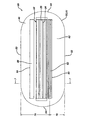
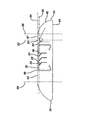
ここで図1〜2を参照すると、かみそりカートリッジ20が示されている。かみそりカートリッジ20は、ブレードユニット22と、ブレードユニット22に固定されかつブレードユニット22を包囲するフレーム40とを備える。ブレードユニット22は、それぞれがブレード縁部24を備える複数個のブレード23を備える。
With reference now to FIGS. 1-2, a
ここで図3〜4を参照すると、ブレードユニット22には、第1の側壁25と、第2の側壁26と、第1の側壁25と第2の側壁26とを相互に連結する端部壁27及び28とが設けられている。第1の側壁25及び第2の側壁26には、第1の接続部材30と第2の接続部材32とが設けられている。好ましくは、第1の接続部材30は、第1の側壁25及び第2の側壁26のそれぞれから外側に延びる突起31を備える。好ましくは、第2の接続部材32は、第1の側壁25及び第2の側壁26のそれぞれの中に凹部33を備える。
3 to 4, the
ブレード23は、一対のクリップ35によってブレードユニット22内に固定される。
各クリップ35は、ブレードユニット22の端部で端部壁27及び28に隣接して配置される。ブレード23はクリップ35によって、ブレード縁部24がクリップ35の底面に接触するように、ブレードユニット22内に固定される。ブレード23は、各々の平行なブレード軸線36に沿って延びる。
The
Each
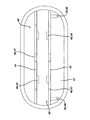
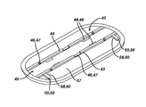
ここで図5〜6を参照すると、フレーム40には、第1の内壁43と、第1の内壁43から離間する第2の内壁44とが設けられて、開口部45を画定する。開口部45は、ブレードユニット22を受容するような寸法に設定されかつ成形される。第1の内壁43及び第2の内壁44には、第1の接続部材46と第2の接続部材48とが設けられる。好ましくは、第1の接続部材46は、第1の内壁43及び第2の内壁44のそれぞれの中に切欠き部47を備える。好ましくは、第2の接続部材48は、第1及び第2の内壁のそれぞれから開口部45内に向かって外側に延びる突起49を備える。
Referring now to FIGS. 5-6, the
内壁43及び44の第1の接続部材46は、側壁25及び26の第1の接続部材30を受容するように構成される。内壁43及び44の第2の接続部材48は、側壁25及び26の第2の接続部材32を受容するように構成される。フレーム40をブレードユニット20に固定する際、突起31は切欠き部47の中にスライドし、突起49は凹部33にはまり込む。
The first connecting member 46 of the
ここで図1及び2を参照すると、フレーム40は周縁部50を有する。フレーム40の周縁部50は、かみそりカートリッジ20のかみそりカートリッジ周縁部51を画定する。周縁部50は、前面52と、後面53と、前面52から後面53に延びる一対の側面54とを備える。フレーム40はまた、上面62と、対向する下面64とを有する。
1 and 2, the
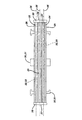
ここで図2、5及び6を参照すると、フレーム40の各末端部には旋回構造体55が存在する。旋回構造体55は、フレーム40の内面57から第1の内壁43に向かって延びて凹部58を画定するアーム56を備える。旋回構造体55の凹部58は、かみそりカートリッジ20の旋回軸60を画定する。
With reference now to FIGS. 2, 5 and 6, there is a pivot structure 55 at each end of the
旋回軸60は、フレーム40内、上面62の下側、下面64の上側、及びブレード軸線36の前方に位置する。旋回軸60は、かみそりカートリッジ20を前方部分70と後方部分74とに分割する。前方部分70は、旋回軸60から前面52へと延びる。後方部分74は、旋回軸60から後面53へと延びる。好ましくは、前方部分は後方部分より小さい。好ましくは、前方部分70は、旋回軸60から前面52まで約6mm〜約12mmの距離延びる。好ましくは、後方部分74は、旋回軸60から後面53まで約15mm〜約20mmの距離延びる。
The
ここで図1を参照すると、上面62の前方部分70はガード80を有する。ガード80は、フレーム40の上面62の、ブレード縁部23に先立って、即ちブレード縁部23の前に皮膚と接触する部分である。ガード80は、好ましくはエラストマー部材82を備える。
Referring now to FIG. 1, the
上面62の後方部分74はキャップ84を備える。キャップ84は、フレーム40の上面62の、ブレード縁部23の後に皮膚と接触する部分である。キャップ84は、好ましくは潤滑部材86を備える。
The
ここで図7を参照すると、ブレード23のブレード縁部24はブレード平面90を画定する。この実施形態において、旋回軸60は、ブレード軸線36の前方に、したがって後面53よりも前面52の近くに位置する。旋回軸60は、フレーム40内、上面62の下側、及び下面64の上側に、旋回軸60を通ってブレード平面90に垂直に引かれた線92が旋回フレーム交点位置93で上面62と交差するように配置される。旋回フレーム交点位置93で上面62に沿って引かれた接線94のような接線は、ブレード平面90と常に平行である。これは、旋回軸60をフレーム40内に適切に配置するための1つの必要条件である。
Referring now to FIG. 7, the
旋回軸60をフレーム40内に適切に配置するための第2の必要条件は、フレーム40が、旋回フレーム交点位置93の前方の上面62上に第1の平坦な表面、及び旋回フレーム交点位置93の後方に位置する上面上に第2の平坦な表面を有さなければならず、かつこれら2つの面が互いに同一平面上にあることである。図7から分かるように、上面62上の第1の平坦な表面96は旋回フレーム交点位置93の前方にあり、上面62上の第2の平坦な表面97は旋回フレーム交点位置93の後方に位置する。第1の平坦な表面96は、第2の平坦な表面97と同一平面上にある。第1の平坦な表面96は、上面62に沿って線92から線98まで延び、第2の平坦な表面97は、上面62に沿って線92から線99まで延びる。
A second requirement for properly positioning the
ここで図8を参照すると、ブレード23のブレード縁部24はブレード平面90を画定する。この実施形態において、旋回軸60は、ブレード軸線36の後方で、したがって前面52よりも後面53の近くに位置する。旋回軸60は、フレーム40内、上面62の下側、及び下面64の上側に、旋回軸60を通ってブレード平面90に垂直に引かれた線92が、旋回フレーム交点位置93で上面62と交差するように配置される。旋回フレーム交点位置93で上面62に沿って引かれた接線94のような接線は、ブレード平面90と常に平行である。これは、旋回軸60をフレーム40内に適切に配置するための1つの必要条件である。
Referring now to FIG. 8, the
旋回軸60をフレーム40内に適切に配置するための第2の必要条件は、フレーム40が、旋回フレーム交点位置93の前方の上面62上に第1の平坦な表面、及び旋回フレーム交点位置93の後方に位置する上面上に第2の平坦な表面を有さなければならず、かつこれら2つの面が互いに同一平面上にあることである。図8から分かるように、上面62上の第1の平坦な表面96は、旋回フレーム交点位置93の前方にあり、上面62上の第2の平坦な表面97は、旋回フレーム交点位置93の後方に位置する。第1の平坦な表面96は、第2の平坦な表面97と同一平面上にある。第1の平坦な表面96は、上面62に沿って線92から線98まで延び、第2の平坦な表面97は、上面62に沿って線92から線99まで延びる。
A second requirement for properly positioning the
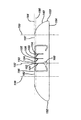
ここで図9を参照すると、第1の剃毛ブレード101は第1のブレード軸線102に沿って延び、最後の剃毛ブレード103は最後のブレード軸線104に沿って延びる。第1の剃毛ブレード101と最後の剃毛ブレード103との間に配置される第2の剃毛ブレード105は、第2のブレード軸線106に沿って延びる。ブレード101、103及び105のブレード縁部124は、ブレード平面190を画定する。この実施形態において、旋回軸160は、第1のブレード軸線102と最後のブレード軸線104との間に位置する。旋回軸160は、前面152及び後面153から等距離に間隔があけられている。旋回軸160は、フレーム140内、上面162の下側、下面164の上側に、旋回軸160を通ってブレード平面190に垂直に引かれた線192が旋回フレーム交点位置193で上面162と交差するように配置される。旋回フレーム交点位置193で上面162に沿って引かれた接線194のような接線は、ブレード平面190と常に平行である。これは、旋回軸160をフレーム140内に適切に配置するための1つの必要条件である。
Referring now to FIG. 9, the
旋回軸160をフレーム140内に適切に配置するための第2の必要条件は、フレーム140が、旋回フレーム交点位置193の前方の上面162上に第1の平坦な表面、及び旋回フレーム交点位置193の後方に位置する上面上に第2の平坦な表面を有さなければならず、かつこれら2つの面が互いに同一平面上にあることである。図9から分かるように、上面162上の第1の平坦な表面196は旋回フレーム交点位置193の前方にあり、上面162上の第2の平坦な表面197は旋回フレーム交点位置193の後方に位置する。第1の平坦な表面196は、第2の平坦な表面197と同一平面上にある。第1の平坦な表面196は、上面162に沿って線192から線198まで延び、第2の平坦な表面197は、上面162に沿って線192から線199まで延びる。
A second requirement for properly positioning the
ここで図10を参照すると、第1の剃毛ブレード101は第1のブレード軸線102に沿って延び、最後の剃毛ブレード103は最後のブレード軸線104に沿って延びる。第1の剃毛ブレード101と最後の剃毛ブレード103との間に配置される第2の剃毛ブレード105は、第2のブレード軸線106に沿って延びる。ブレード101、103及び105のブレード縁部124は、ブレード平面190を画定する。この実施形態において、旋回軸160は、第1のブレード軸線102に位置する。旋回軸160は、後面153よりも前面152に近接するように間隔があけられている。旋回軸160は、フレーム140内、上面162の下側、及び下面164の上側に、旋回軸160を通ってブレード平面190に垂直に引かれた線192が旋回フレーム交点位置193で上面162と交差するように配置される。旋回フレーム交点位置193で上面162に沿って引かれた接線194のような接線は、ブレード平面190と常に平行である。これは、旋回軸160をフレーム140内に適切に配置するための1つの必要条件である。
Referring now to FIG. 10, the
旋回軸160をフレーム140内に適切に配置するための第2の必要条件は、フレーム140が、旋回フレーム交点位置193の前方の上面162上に第1の平坦な表面、及び旋回フレーム交点位置193の後方に位置する上面上に第2の平坦な表面を有さなければならず、かつこれら2つの面が互いに同一平面上にあることである。図10から分かるように、上面162上の第1の平坦な表面196は旋回フレーム交点位置193の前方にあり、上面162上の第2の平坦な表面197は旋回フレーム交点位置193の後方に位置する。第1の平坦な表面196は、第2の平坦な表面197と同一平面上にある。第1の平坦な表面196は、上面162に沿って線192から線198まで延び、第2の平坦な表面197は、上面162に沿って線192から線199まで延びる。
A second requirement for properly positioning the
ここで図11を参照すると、第1の剃毛ブレード101は第1のブレード軸線102に沿って延び、最後の剃毛ブレード103は最後のブレード軸線104に沿って延びる。第1の剃毛ブレード101と最後の剃毛ブレード103との間に配置される第2の剃毛ブレード105は、第2のブレード軸線106に沿って延びる。ブレード101、103及び105のブレード縁部124は、ブレード平面190を画定する。この実施形態において、旋回軸160は第2のブレード軸線104に位置する。旋回軸160は、前面152よりも後面153に近接するように間隔があけられている。旋回軸160は、フレーム140内、上面162の下側、及び下面164の上側に、旋回軸160を通ってブレード平面190に垂直に引かれた線192が旋回フレーム交点位置193で上面162と交差するように配置される。旋回フレーム交点位置193で上面162に沿って引かれた接線194のような接線は、ブレード平面190と常に平行である。これは、旋回軸160をフレーム140内に適切に配置するための1つの必要条件である。
Referring now to FIG. 11, the
旋回軸160をフレーム140内に適切に配置するための第2の必要条件は、フレーム140が、旋回フレーム交点位置193の前方の上面162上に第1の平坦な表面、及び旋回フレーム交点位置193の後方に位置する上面上に第2の平坦な表面を有さなければならず、かつこれら2つの面が互いに同一平面上にあることである。図11から分かるように、上面162上の第1の平坦な表面196は旋回フレーム交点位置193の前方にあり、上面162上の第2の平坦な表面197は旋回フレーム交点位置193の後方に位置する。第1の平坦な表面196は、第2の平坦な表面197と同一平面上にある。第1の平坦な表面196は、上面162に沿って線192から線198まで延び、第2の平坦な表面197は、上面162に沿って線192から線199まで延びる。
A second requirement for properly positioning the
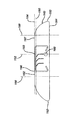
ここで図12を参照すると、かみそりカートリッジ220が示されている。かみそりカートリッジ220は、ブレードユニット222と、ブレードユニット222に固定されかつブレードユニット222を包囲するフレーム240とを備える。ブレードユニット222は、それぞれがブレード縁部224を備える複数個のブレード223を備える。かみそりカートリッジ220は、ブレード223をブレードユニット222内に固定するためにクリップを使用していないこと以外は、図1のかみそりカートリッジ20と同一である。
その代わり、ブレード223をブレードユニット222内に維持するために、フレーム240の一部分がブレードユニット222の各末端部上に延びている。図12のフレーム240の一端の一部を切り取ると、ブレードユニット222内の、下層のブレード223が露呈する。
Referring now to FIG. 12, a
Instead, a portion of the
本明細書に開示されている寸法及び値は、列挙した正確な数値に厳しく限定されるものとして理解すべきではない。それよりむしろ、特に規定がない限り、こうした各寸法は、列挙された値とその値周辺の機能的に同等の範囲との両方を意味することを意図している。例えば、「40mm」として開示された寸法は、「約40mm」を意味することを意図する。 The dimensions and values disclosed herein are not to be understood as being strictly limited to the exact numerical values recited. Instead, unless otherwise specified, each such dimension is intended to mean both the recited value and a functionally equivalent range surrounding that value. For example, a dimension disclosed as “40 mm” is intended to mean “about 40 mm”.
「発明を実施するための形態」で引用した全ての文献は、その関連部分において本明細書に参照により組み込まれ、いかなる文献の引用も、それが本発明に対する先行技術であることを認めるものと解釈すべきではない。本書における用語のいかなる意味又は定義も、参照により組み込まれた文献における同一の用語のいかなる意味又は定義と相反する限りにおいては、本書においてその用語に与えられた意味又は定義が適用されるものとする。 All documents cited in “Mode for Carrying Out the Invention” are incorporated herein by reference in their relevant parts and any citation of any document shall be recognized as prior art to the present invention. Should not be interpreted. To the extent that any meaning or definition of a term in this document conflicts with any meaning or definition of the same term in a document incorporated by reference, the meaning or definition given to that term in this document shall apply. .
本発明の特定の諸実施形態を図示し、記載したが、本発明の趣旨及び範囲から逸脱することなく他の様々な変更及び修正を実施できることは当業者には自明であろう。したがって、本発明の範囲内にあるかような全ての変更及び修正は、添付の特許請求の範囲に包含されるものとする。 While particular embodiments of the present invention have been illustrated and described, it would be obvious to those skilled in the art that various other changes and modifications can be made without departing from the spirit and scope of the invention. Accordingly, all changes and modifications that come within the scope of the invention are intended to be covered by the appended claims.
Claims (8)
複数個の剃毛ブレードを備えるブレードユニットであって、前記剃毛ブレードは各々の平行なブレード軸線に沿って延び、該剃毛ブレードは鋭利な縁部を含み、前記鋭利な縁部はブレード平面を画定する、ブレードユニットと、
前記ブレードユニットに固定されるフレームであって、前記フレームはフレーム周縁部と、上面と、旋回構造体とを有し、前記フレーム周縁部は前記かみそりカートリッジのかみそりカートリッジ周縁部を画定し、前記旋回構造体は前記かみそりカートリッジを前記ハンドルに対して旋回させるための旋回軸を画定し、前記旋回軸は該フレーム内に、前記旋回軸を通って前記ブレード平面に垂直に引かれた線が旋回フレーム交点位置で該フレームの前記上面と交差するように配置され、ここで前記旋回フレーム交点位置で前記上面に沿って引かれた接線は、該ブレード平面と平行である、フレームと、
前記旋回フレーム交点位置の前方に位置する前記上面上の第1の平坦な表面、及び前記旋回フレーム交点位置の後方に位置する前記上面上の第2の平坦な表面であって、該第1の平坦な表面は該第2の平坦な表面と同一平面上にある、第1の平坦な表面及び第2の平坦な表面と、
を備える、かみそりカートリッジ。 A razor cartridge for connection to a handle,
A blade unit comprising a plurality of shaving blades, said shaving blades extending along each parallel blade axis, said shaving blades comprising sharp edges, said sharp edges being blade planes Defining a blade unit; and
A frame fixed to the blade unit, the frame having a frame peripheral edge, an upper surface, and a pivot structure; the frame peripheral edge defining a razor cartridge peripheral edge of the razor cartridge; A structure defines a pivot axis for pivoting the razor cartridge with respect to the handle, the pivot axis being in the frame and a line drawn perpendicularly to the blade plane through the pivot axis. A frame that is arranged to intersect the upper surface of the frame at an intersection location, wherein a tangent line drawn along the upper surface at the pivot frame intersection location is parallel to the blade plane;
A first flat surface on the upper surface located in front of the swivel frame intersection position and a second flat surface on the upper surface located behind the swivel frame intersection position, the first surface A first planar surface and a second planar surface, wherein the planar surface is coplanar with the second planar surface;
A razor cartridge comprising:
Applications Claiming Priority (2)
| Application Number | Priority Date | Filing Date | Title |
|---|---|---|---|
| US11/788,672 | 2007-04-20 | ||
| US11/788,672 US20080256803A1 (en) | 2007-04-20 | 2007-04-20 | Razor cartridge pivot axis |
Related Parent Applications (1)
| Application Number | Title | Priority Date | Filing Date |
|---|---|---|---|
| JP2010503658A Division JP2010523298A (en) | 2007-04-20 | 2008-04-18 | Razor cartridge pivot |
Publications (1)
| Publication Number | Publication Date |
|---|---|
| JP2014111165A true JP2014111165A (en) | 2014-06-19 |
Family
ID=39592013
Family Applications (2)
| Application Number | Title | Priority Date | Filing Date |
|---|---|---|---|
| JP2010503658A Pending JP2010523298A (en) | 2007-04-20 | 2008-04-18 | Razor cartridge pivot |
| JP2014018565A Pending JP2014111165A (en) | 2007-04-20 | 2014-02-03 | Razor cartridge pivot axis |
Family Applications Before (1)
| Application Number | Title | Priority Date | Filing Date |
|---|---|---|---|
| JP2010503658A Pending JP2010523298A (en) | 2007-04-20 | 2008-04-18 | Razor cartridge pivot |
Country Status (15)
| Country | Link |
|---|---|
| US (2) | US20080256803A1 (en) |
| EP (2) | EP2136973B1 (en) |
| JP (2) | JP2010523298A (en) |
| KR (1) | KR20090120521A (en) |
| CN (2) | CN101663137A (en) |
| AU (1) | AU2008242192B2 (en) |
| BR (1) | BRPI0810153A8 (en) |
| CA (1) | CA2683837C (en) |
| CL (1) | CL2008001132A1 (en) |
| IL (1) | IL201504A0 (en) |
| MX (1) | MX2009011195A (en) |
| RU (1) | RU2408454C1 (en) |
| TW (1) | TW200911487A (en) |
| WO (1) | WO2008129499A1 (en) |
| ZA (1) | ZA200907061B (en) |
Families Citing this family (31)
| Publication number | Priority date | Publication date | Assignee | Title |
|---|---|---|---|---|
| US9517570B2 (en) * | 2007-04-20 | 2016-12-13 | The Gillette Company | Razor cartridge |
| US7770294B2 (en) * | 2007-08-30 | 2010-08-10 | The Gillette Company | Razor with blade unit biasing member |
| AU2009260609A1 (en) * | 2008-06-19 | 2009-12-23 | The Gillette Company | Safety razor having pivotable blade unit |
| KR101068271B1 (en) | 2010-09-17 | 2011-09-28 | 주식회사 도루코 | Reciprocation linear razor |
| EP2591895B1 (en) * | 2011-11-10 | 2019-02-27 | The Gillette Company LLC | Razor cartridge with lubrication and moisturizing strips |
| KR101499287B1 (en) * | 2012-06-13 | 2015-03-05 | 주식회사 도루코 | Comb guard razor cartridge |
| JP6093550B2 (en) | 2012-11-06 | 2017-03-08 | 株式会社貝印刃物開発センター | razor |
| KR101977753B1 (en) * | 2012-12-21 | 2019-08-28 | 빅-비올렉스 에스아 | Shaver with interchangeable cartridge, cartridge and head and handle assembly for such shaver |
| CN105358295B (en) | 2013-06-04 | 2017-06-13 | 比克-维尔莱克 | For the shaving aid connector of razor shelf |
| JP6208339B2 (en) * | 2013-06-19 | 2017-10-04 | ビック・バイオレクス・エス・エー | Shaving blade assembly |
| EP3166761B1 (en) * | 2014-07-11 | 2019-04-10 | Shavelogic, Inc. | Razor cartridges |
| CN107000231A (en) * | 2014-12-10 | 2017-08-01 | 比克-维尔莱克 | Razor blade assembly including blade unit and skin contact element and the shaver including shaving razor handle He the razor blade assembly |
| JP1531818S (en) * | 2014-12-15 | 2015-08-24 | ||
| USD778498S1 (en) * | 2015-03-26 | 2017-02-07 | Societe Bic | Razor cartridge shaving aid assembly |
| EP3317064B1 (en) | 2015-06-30 | 2022-09-28 | The Gillette Company LLC | Method of manufacturing polymeric cutting edge structures |
| PL3191268T3 (en) | 2015-12-01 | 2020-07-13 | Bic-Violex S.A. | Shaving razors and shaving cartridges |
| USD795497S1 (en) | 2016-01-15 | 2017-08-22 | Medline Industries, Inc. | Clipper |
| USD794871S1 (en) | 2016-01-15 | 2017-08-15 | Medline Industries, Inc. | Clipper |
| USD802217S1 (en) | 2016-06-10 | 2017-11-07 | Medline Industries, Inc. | Clipper head |
| USD802215S1 (en) | 2016-06-10 | 2017-11-07 | Medline Industries, Inc. | Clipper head |
| USD802214S1 (en) | 2016-06-10 | 2017-11-07 | Medline Industries, Inc. | Clipper head |
| USD802216S1 (en) | 2016-06-10 | 2017-11-07 | Medline Industries, Inc. | Clipper head |
| USD877983S1 (en) | 2016-09-09 | 2020-03-10 | The Gillette Company Llc | Shaving razor cartridge |
| EP3292965B1 (en) | 2016-09-09 | 2021-05-26 | The Gillette Company LLC | Shaving razor cartridge and method of assembling |
| CN106625792A (en) * | 2017-02-27 | 2017-05-10 | 贵州裕隆实业有限公司 | Blade support of shaver and blade assembly |
| US11117278B2 (en) | 2017-06-06 | 2021-09-14 | The Gillette Company Llc | Shaving razor cartridge |
| US10882200B1 (en) * | 2018-12-12 | 2021-01-05 | Mark Shabel | Razor with rotatable blade head |
| USD921984S1 (en) | 2019-03-19 | 2021-06-08 | The Gillette Company Llc | Shaving razor cartridge |
| AU2020253440B2 (en) | 2019-04-04 | 2023-09-14 | The Gillette Company Llc | Razor cartridge |
| USD926374S1 (en) | 2019-04-04 | 2021-07-27 | The Gillette Company Llc | Shaving razor cartridge cover |
| USD1016392S1 (en) | 2020-09-24 | 2024-02-27 | The Gillette Company Llc | Shaving razor cartridge |
Citations (4)
| Publication number | Priority date | Publication date | Assignee | Title |
|---|---|---|---|---|
| JPH06500488A (en) * | 1990-09-10 | 1994-01-20 | ザ、ジレット、カンパニー | razor blade assembly |
| WO2005090021A2 (en) * | 2004-03-11 | 2005-09-29 | The Gillette Company | Shaving system |
| WO2006036591A1 (en) * | 2004-09-24 | 2006-04-06 | Eveready Battery Company, Inc. | Shaving implement employing discrete cartridge sections |
| WO2007015220A1 (en) * | 2005-08-03 | 2007-02-08 | The Gillette Company | Razors |
Family Cites Families (31)
| Publication number | Priority date | Publication date | Assignee | Title |
|---|---|---|---|---|
| US4442598A (en) * | 1981-01-30 | 1984-04-17 | The Gillette Company | Razor blade assembly |
| US4621424A (en) * | 1982-09-17 | 1986-11-11 | The Gillette Company | Razor blade assembly |
| US4498235A (en) * | 1982-09-17 | 1985-02-12 | The Gillette Company | Razor blade assembly |
| DE9004761U1 (en) * | 1990-04-27 | 1991-08-29 | Wilkinson Sword Gmbh, 5650 Solingen, De | |
| US4984365A (en) | 1990-05-04 | 1991-01-15 | The Gillette Company | Safety razor |
| DE9108213U1 (en) * | 1991-07-03 | 1992-10-29 | Wilkinson Sword Gmbh, 5650 Solingen, De | |
| US6161288A (en) * | 1993-02-22 | 2000-12-19 | Andrews; Edward A. | Four blade bi-directional razor structure with flexible guard system |
| US5689883A (en) * | 1995-05-08 | 1997-11-25 | Warner-Lambert Company | Shaving implement |
| US6185823B1 (en) | 1995-11-10 | 2001-02-13 | The Gillette Company | Oval frame razor |
| US5787586A (en) | 1996-04-10 | 1998-08-04 | The Gillette Company | Shaving system and method |
| US5661907A (en) * | 1996-04-10 | 1997-09-02 | The Gillette Company | Razor blade assembly |
| GB9715501D0 (en) * | 1997-07-22 | 1997-10-01 | Gillette Co | Safety razors |
| US6035537A (en) * | 1997-09-30 | 2000-03-14 | The Gillette Company | Razor cartridge with metal clip retaining blades |
| US6161287A (en) | 1998-04-24 | 2000-12-19 | The Gillette Company | Razor blade system |
| CA2301468A1 (en) * | 1999-04-21 | 2000-10-21 | Warner-Lambert Company | Razor assembly and cartridge with wash-through holes |
| US6145201A (en) * | 1999-07-27 | 2000-11-14 | Andrews; Edward A. | Underarm shaving devices |
| US6216345B1 (en) | 1999-07-27 | 2001-04-17 | Edward A. Andrews | Glide systems for manual shaving razors |
| JP5032729B2 (en) * | 1999-11-29 | 2012-09-26 | コーニンクレッカ フィリップス エレクトロニクス エヌ ヴィ | A shaving head having a subframe and a main frame and a shaving device including such a shaving head |
| US6349471B1 (en) * | 2000-07-19 | 2002-02-26 | The Gillette Company | Razor cartridge with painted and drawn retaining clip |
| US7200942B2 (en) * | 2001-03-28 | 2007-04-10 | Eveready Battery Company, Inc. | Safety razor with pivot point shift from center to guard-bar under applied load |
| JP2006514576A (en) * | 2003-01-28 | 2006-05-11 | エバレディ バッテリー カンパニー インコーポレーテッド | Leather blade platform and leather cartridge using the same |
| GB2406537B (en) * | 2003-07-21 | 2006-09-06 | Gillette Co | Safety razors |
| US7103976B2 (en) * | 2004-02-06 | 2006-09-12 | Eveready Battery Company, Inc. | Razor assembly |
| US7272991B2 (en) * | 2004-02-09 | 2007-09-25 | The Gillette Company | Shaving razors, and blade subassemblies therefor and methods of manufacture |
| US7197825B2 (en) * | 2004-03-11 | 2007-04-03 | The Gillette Company | Razors and shaving cartridges with guard |
| US20050198830A1 (en) | 2004-03-11 | 2005-09-15 | Walker Vincent P. | Shaving cartridges and razors |
| US20060080837A1 (en) * | 2004-10-20 | 2006-04-20 | Robert Johnson | Shaving razors and cartridges |
| JP5010896B2 (en) * | 2006-10-31 | 2012-08-29 | 株式会社貝印刃物開発センター | razor |
| US20080256800A1 (en) * | 2007-04-20 | 2008-10-23 | Roy Nicoll | Razor cartridge assembly with movable face |
| USD563043S1 (en) * | 2007-08-30 | 2008-02-26 | The Gillette Company | Razor cartridge lubrication member |
| US9308657B2 (en) * | 2008-05-30 | 2016-04-12 | The Gillette Company | Blade support for multi-blade razor cartridges |
-
2007
- 2007-04-20 US US11/788,672 patent/US20080256803A1/en not_active Abandoned
-
2008
- 2008-04-18 EP EP08737921.0A patent/EP2136973B1/en active Active
- 2008-04-18 RU RU2009136470/02A patent/RU2408454C1/en not_active IP Right Cessation
- 2008-04-18 JP JP2010503658A patent/JP2010523298A/en active Pending
- 2008-04-18 KR KR1020097021802A patent/KR20090120521A/en not_active Application Discontinuation
- 2008-04-18 CN CN200880012800A patent/CN101663137A/en active Pending
- 2008-04-18 EP EP13162330.8A patent/EP2623277A3/en not_active Withdrawn
- 2008-04-18 CN CN201310176501.0A patent/CN103273512B/en active Active
- 2008-04-18 CA CA2683837A patent/CA2683837C/en not_active Expired - Fee Related
- 2008-04-18 AU AU2008242192A patent/AU2008242192B2/en not_active Ceased
- 2008-04-18 CL CL2008001132A patent/CL2008001132A1/en unknown
- 2008-04-18 BR BRPI0810153A patent/BRPI0810153A8/en not_active IP Right Cessation
- 2008-04-18 WO PCT/IB2008/051512 patent/WO2008129499A1/en active Application Filing
- 2008-04-18 MX MX2009011195A patent/MX2009011195A/en active IP Right Grant
- 2008-04-18 TW TW097114422A patent/TW200911487A/en unknown
-
2009
- 2009-10-09 ZA ZA200907061A patent/ZA200907061B/en unknown
- 2009-10-14 IL IL201504A patent/IL201504A0/en unknown
-
2012
- 2012-01-27 US US13/359,795 patent/US8327546B2/en active Active
-
2014
- 2014-02-03 JP JP2014018565A patent/JP2014111165A/en active Pending
Patent Citations (4)
| Publication number | Priority date | Publication date | Assignee | Title |
|---|---|---|---|---|
| JPH06500488A (en) * | 1990-09-10 | 1994-01-20 | ザ、ジレット、カンパニー | razor blade assembly |
| WO2005090021A2 (en) * | 2004-03-11 | 2005-09-29 | The Gillette Company | Shaving system |
| WO2006036591A1 (en) * | 2004-09-24 | 2006-04-06 | Eveready Battery Company, Inc. | Shaving implement employing discrete cartridge sections |
| WO2007015220A1 (en) * | 2005-08-03 | 2007-02-08 | The Gillette Company | Razors |
Also Published As
| Publication number | Publication date |
|---|---|
| BRPI0810153A2 (en) | 2014-12-30 |
| US20080256803A1 (en) | 2008-10-23 |
| CA2683837C (en) | 2012-12-04 |
| EP2136973B1 (en) | 2019-01-02 |
| EP2623277A3 (en) | 2014-03-12 |
| JP2010523298A (en) | 2010-07-15 |
| CN103273512B (en) | 2016-07-13 |
| AU2008242192B2 (en) | 2014-03-27 |
| CN101663137A (en) | 2010-03-03 |
| AU2008242192A1 (en) | 2008-10-30 |
| EP2623277A2 (en) | 2013-08-07 |
| CL2008001132A1 (en) | 2009-01-23 |
| US8327546B2 (en) | 2012-12-11 |
| CN103273512A (en) | 2013-09-04 |
| IL201504A0 (en) | 2010-05-31 |
| TW200911487A (en) | 2009-03-16 |
| CA2683837A1 (en) | 2008-10-30 |
| BRPI0810153A8 (en) | 2019-01-15 |
| EP2136973A1 (en) | 2009-12-30 |
| MX2009011195A (en) | 2009-10-30 |
| US20120117782A1 (en) | 2012-05-17 |
| WO2008129499A1 (en) | 2008-10-30 |
| KR20090120521A (en) | 2009-11-24 |
| ZA200907061B (en) | 2010-07-28 |
| RU2408454C1 (en) | 2011-01-10 |
Similar Documents
| Publication | Publication Date | Title |
|---|---|---|
| JP2014111165A (en) | Razor cartridge pivot axis | |
| US9517570B2 (en) | Razor cartridge | |
| JP5269880B2 (en) | Array of razor cartridges | |
| CA3004474C (en) | Shaving razors and shaving cartridges | |
| US10773403B2 (en) | Shaving razor handle | |
| CA2683835C (en) | Razor cartridge with front pivot axis | |
| US20160279815A1 (en) | Shaving razor cartridge | |
| CN107073730B (en) | Razor shelf and shaver including the razor shelf | |
| KR20110090249A (en) | Razor cartridge | |
| US20160279816A1 (en) | Shaving razor cartridge | |
| AU2014203046B2 (en) | Razor cartridge pivot axis | |
| KR101136349B1 (en) | Razor Cartridge | |
| KR20210146118A (en) | Razor Cartridge |
Legal Events
| Date | Code | Title | Description |
|---|---|---|---|
| A621 | Written request for application examination |
Free format text: JAPANESE INTERMEDIATE CODE: A621 Effective date: 20140305 |
|
| A131 | Notification of reasons for refusal |
Free format text: JAPANESE INTERMEDIATE CODE: A131 Effective date: 20150113 |
|
| A977 | Report on retrieval |
Free format text: JAPANESE INTERMEDIATE CODE: A971007 Effective date: 20150114 |
|
| A601 | Written request for extension of time |
Free format text: JAPANESE INTERMEDIATE CODE: A601 Effective date: 20150413 |
|
| A601 | Written request for extension of time |
Free format text: JAPANESE INTERMEDIATE CODE: A601 Effective date: 20150513 |
|
| A521 | Request for written amendment filed |
Free format text: JAPANESE INTERMEDIATE CODE: A523 Effective date: 20150514 |
|
| A02 | Decision of refusal |
Free format text: JAPANESE INTERMEDIATE CODE: A02 Effective date: 20150814 |