JP2014106983A - Optical detector position adjustment method in optical pickup device, and optical pickup device - Google Patents
Optical detector position adjustment method in optical pickup device, and optical pickup device Download PDFInfo
- Publication number
- JP2014106983A JP2014106983A JP2012256700A JP2012256700A JP2014106983A JP 2014106983 A JP2014106983 A JP 2014106983A JP 2012256700 A JP2012256700 A JP 2012256700A JP 2012256700 A JP2012256700 A JP 2012256700A JP 2014106983 A JP2014106983 A JP 2014106983A
- Authority
- JP
- Japan
- Prior art keywords
- light
- optical pickup
- pickup device
- sensor
- photodetector
- Prior art date
- Legal status (The legal status is an assumption and is not a legal conclusion. Google has not performed a legal analysis and makes no representation as to the accuracy of the status listed.)
- Pending
Links
- 230000003287 optical effect Effects 0.000 title claims abstract description 106
- 238000000034 method Methods 0.000 title claims abstract description 31
- 238000004364 calculation method Methods 0.000 claims description 6
- 230000001678 irradiating effect Effects 0.000 claims description 3
- 238000012360 testing method Methods 0.000 abstract description 15
- 239000004065 semiconductor Substances 0.000 description 17
- 201000009310 astigmatism Diseases 0.000 description 12
- 239000000758 substrate Substances 0.000 description 12
- 238000012545 processing Methods 0.000 description 9
- 238000010586 diagram Methods 0.000 description 7
- 230000002093 peripheral effect Effects 0.000 description 5
- 230000000630 rising effect Effects 0.000 description 5
- 229910004298 SiO 2 Inorganic materials 0.000 description 4
- 230000000694 effects Effects 0.000 description 4
- 239000011521 glass Substances 0.000 description 3
- 230000004075 alteration Effects 0.000 description 2
- 230000014509 gene expression Effects 0.000 description 2
- 238000009434 installation Methods 0.000 description 2
- 230000010287 polarization Effects 0.000 description 2
- 239000002131 composite material Substances 0.000 description 1
- 239000000470 constituent Substances 0.000 description 1
- 238000013461 design Methods 0.000 description 1
- 238000005530 etching Methods 0.000 description 1
- 238000004519 manufacturing process Methods 0.000 description 1
- 238000012986 modification Methods 0.000 description 1
- 230000004048 modification Effects 0.000 description 1
- 238000004088 simulation Methods 0.000 description 1
Images
Landscapes
- Moving Of The Head For Recording And Reproducing By Optical Means (AREA)
- Optical Recording Or Reproduction (AREA)
- Optical Head (AREA)
Abstract
Description
本発明は、複数波長のレーザ光を光ディスクに照射する光ピックアップ装置および当該光ピックアップ装置に内蔵される光検出器の位置調整方法に関する。 The present invention relates to an optical pickup device that irradiates an optical disc with laser beams having a plurality of wavelengths, and a method for adjusting the position of a photodetector built in the optical pickup device.
従来、複数種類の光ディスクに対応した互換型の光ピックアップ装置が開発されている。かかる光ピックアップ装置では、異なる波長のレーザ光を用いて情報の読み書きが行われる。この種の光ピックアップ装置で用いられる半導体レーザとして、異なる波長の2つのレーザ光を出射する2波長レーザが知られている(たとえば、特許文献1)。さらに、近年では、異なる波長の3つのレーザ光を出射する3波長レーザが用いられつつある。 Conventionally, compatible optical pickup devices corresponding to a plurality of types of optical discs have been developed. In such an optical pickup device, information is read and written using laser beams having different wavelengths. As a semiconductor laser used in this type of optical pickup device, a two-wavelength laser that emits two laser beams having different wavelengths is known (for example, Patent Document 1). Furthermore, in recent years, a three-wavelength laser that emits three laser beams having different wavelengths is being used.
このように異なる波長のレーザ光を出射する半導体レーザを用いることにより、部品点数の削減を図ることができる。さらに、異なる波長のレーザ光の光軸を光検出器上において一致させることにより、光検出器のセンサレイアウトを簡素化することができる。ここで、2つのレーザ光の光軸を一致させるための光学素子として、たとえば、回折光学素子が用いられる(たとえば、特許文献2)。 By using a semiconductor laser that emits laser beams having different wavelengths as described above, the number of components can be reduced. Furthermore, by aligning the optical axes of laser beams having different wavelengths on the photodetector, the sensor layout of the photodetector can be simplified. Here, for example, a diffractive optical element is used as an optical element for matching the optical axes of the two laser beams (for example, Patent Document 2).
上記のように光源として3波長レーザが用いられる場合、回折光学素子は、通常、3つのレーザ光のうち一つのレーザ光の光軸を曲げるように設計される。この場合、各レーザ光の回折効率を高めるために、いわゆるブレーズ型の回折光学素子が用いられる。 When a three-wavelength laser is used as the light source as described above, the diffractive optical element is usually designed to bend the optical axis of one of the three laser beams. In this case, a so-called blazed diffractive optical element is used to increase the diffraction efficiency of each laser beam.
しかしながら、ブレーズ型の回折光学素子は、回折溝の構造が複雑であるため高価であり、このため、光ピックアップ装置のコストを引き上げる要因となる。これに対し、レーザ光を0次回折光と、+1次回折光と、−1次回折光とに分割するために用いられる所謂2ステップ型の回折格子を用いることによりコストの低減を図ることができる。しかしながら、2ステップ型の回折格子を回折光学素子として用いる場合には、3つのレーザ光のうち2つのレーザ光の光軸を曲げなければ、各レーザ光に対して所望の回折効率が得られないことが考えられる。 However, the blaze-type diffractive optical element is expensive because the structure of the diffraction groove is complicated, and this increases the cost of the optical pickup device. On the other hand, the cost can be reduced by using a so-called two-step type diffraction grating that is used to divide the laser light into zero-order diffracted light, + 1st-order diffracted light, and −1st-order diffracted light. However, when a two-step type diffraction grating is used as a diffractive optical element, a desired diffraction efficiency cannot be obtained for each laser beam unless the optical axes of the two laser beams out of the three laser beams are bent. It is possible.
その一方、光ピックアップ装置では、ディスクからの反射光が光検出器によって適正に受光されるように、光検出器の位置調整が行われる。この調整は、なるべく簡素な作業にて行われるのが望ましい。したがって、上記のように3つのレーザ光のうち2つのレーザ光の光軸を曲げるよう回折光学素子が設計される場合には、光軸を曲げない一つのレーザ光を用いて光検出器の位置調整が行われることが望ましい。 On the other hand, in the optical pickup device, the position of the photodetector is adjusted so that the reflected light from the disk is properly received by the photodetector. This adjustment is preferably performed as simple as possible. Therefore, when the diffractive optical element is designed so as to bend the optical axes of two of the three laser beams as described above, the position of the photodetector is detected using one laser beam that does not bend the optical axis. It is desirable to make adjustments.
このような事情に鑑み、本発明は、3つのレーザ光のうち2つのレーザ光の光軸を回折光学素子によって一致させる場合に、光検出器の位置調整を簡素な作業にて行うことが可能な光ピックアップ装置および光検出器の位置調整方法を提供することを目的とする。 In view of such circumstances, in the present invention, when the optical axes of two of the three laser beams are matched by the diffractive optical element, the position adjustment of the photodetector can be performed with a simple operation. An object of the present invention is to provide an optical pickup device and a method for adjusting the position of a photodetector.
本発明の第1の態様は、光ピックアップ装置における光検出器の位置調整方法に関する。前記光ピックアップ装置は、互いに異なる波長の第1、第2および第3のレーザ光をそれぞれ出射する第1、第2および第3の発光部が同一パッケージ上に直線状に配置されたレーザ光源と、前記第1の発光部から出射された前記第1のレーザ光をメインビームと2つのサブビームに分割する第1の回折格子と、前記第1のレーザ光に対応する第1のディスクによって反射された前記メインビームの反射光を受光する第1の4分割センサと、前記第1のディスクによって反射された前記2つのサブビームの反射光をそれぞれ受光する2つの第2の4分割センサとを有する光検出器と、を備える。この態様に係る光ピックアップ装置における光検出器の位置調整方法は、前記第1のレーザ光に対応する第1の基準ディスクに対して前記第1のレーザ光を照射したときに、前記第1の4分割センサと前記第2の4分割センサから出力される信号に基づいて、前記メインビームと前記2つのサブビームが前記第1の基準ディスク上のトラックに対して適正に位置付けられるよう、前記第1の回折格子の回転位置を調整する第1の調整工程と、前記第1の調整工程の後に、前記第1の基準ディスクに対して前記第1のレーザ光を照射したときに、前記第2の4分割センサから出力される信号に基づいて、前記第1の4分割センサの2つの分割線の交点を中心とする前記光検出器の回転位置を調整する第2の調整工程と、を含む。 A first aspect of the present invention relates to a method for adjusting the position of a photodetector in an optical pickup device. The optical pickup device includes: a laser light source in which first, second, and third light emitting units that respectively emit first, second, and third laser beams having different wavelengths are arranged linearly on the same package; The first laser beam emitted from the first light emitting unit is reflected by a first diffraction grating that divides the first laser beam into a main beam and two sub beams, and a first disk corresponding to the first laser beam. A first quadrant sensor that receives the reflected light of the main beam, and two second quadrant sensors that respectively receive the reflected light of the two sub beams reflected by the first disk. And a detector. The position adjustment method of the photodetector in the optical pickup device according to this aspect includes the first laser beam when the first laser beam is irradiated to the first reference disk corresponding to the first laser beam. Based on the signals output from the quadrant sensor and the second quadrant sensor, the first beam and the two sub-beams are appropriately positioned with respect to the track on the first reference disk. After the first adjustment step of adjusting the rotational position of the diffraction grating and the first adjustment step, the second laser beam is irradiated when the first laser light is irradiated onto the first reference disk. And a second adjustment step of adjusting the rotational position of the photodetector around the intersection of two dividing lines of the first four-divided sensor based on a signal output from the four-divided sensor.
本発明の第2の態様は、光ピックアップ装置に関する。この態様に係る光ピックアップ装置は、互いに異なる波長の第1、第2および第3のレーザ光をそれぞれ出射する第1、第2および第3の発光部が同一パッケージ上に直線状に配置されたレーザ光源と、前記第1の発光部から出射された前記第1のレーザ光をメインビームと2つのサブビームに分割する第1の回折格子と、前記第1のレーザ光に対応する第1のディスクによって反射された前記メインビームの反射光を受光する第1の4分割センサと、前記第1のディスクによって反射された前記2つのサブビームの反射光をそれぞれ受光する2つの第2の4分割センサとを有する光検出器と、前記光検出器から出力される信号から所定の信号を生成する信号演算回路と、を備える。ここで、前記信号演算回路は、前記第1の4分割センサの各センサから出力される信号のうち所定の信号を選択する第1のセレクタと、前記第2の4分割センサの各センサから出力される信号のうち所定の信号を選択する複数の第2のセレクタと、を有する。前記第1のセレクタと前記第2のセレクタは、前記第1のレーザ光に対応する第1の基準ディスクに対して前記第1のレーザ光を照射しながら、前記メインビームと前記2つのサブビームが前記第1の基準ディスク上のトラックに対して適正に位置付けられるよう、前記第1の回折格子の回転位置を調整する際に用いられる第1の調整信号を出力する第1の選択モードと、前記第1の基準ディスクに対して前記第1のレーザ光を照射しながら、前記第1の4分割センサの2つの分割線の交点を中心とする前記光検出器の回転位置を調整する際に用いられる第2の調整信号を出力する第2の選択モードと、を含む。 A second aspect of the present invention relates to an optical pickup device. In the optical pickup device according to this aspect, the first, second, and third light emitting units that respectively emit the first, second, and third laser beams having different wavelengths are linearly arranged on the same package. A laser light source, a first diffraction grating that divides the first laser light emitted from the first light emitting unit into a main beam and two sub beams, and a first disk corresponding to the first laser light A first quadrant sensor that receives the reflected light of the main beam reflected by the first disc, and two second quadrant sensors that respectively receive the reflected light of the two sub beams reflected by the first disk; And a signal arithmetic circuit that generates a predetermined signal from the signal output from the photodetector. Here, the signal calculation circuit outputs a first selector that selects a predetermined signal among signals output from the sensors of the first four-divided sensor and outputs from the sensors of the second four-divided sensor. And a plurality of second selectors for selecting a predetermined signal among the signals to be processed. While the first selector and the second selector irradiate the first laser beam to the first reference disk corresponding to the first laser beam, the main beam and the two sub beams are A first selection mode for outputting a first adjustment signal used for adjusting a rotational position of the first diffraction grating so as to be properly positioned with respect to a track on the first reference disk; Used to adjust the rotational position of the photodetector around the intersection of two dividing lines of the first four-divided sensor while irradiating the first laser beam to the first reference disk. And a second selection mode for outputting a second adjustment signal.
本発明によれば、3つのレーザ光のうち2つのレーザ光の光軸を回折光学素子によって一致させる場合に、光検出器の位置調整を簡素な作業にて行うことが可能な光ピックアップ装置および光検出器の位置調整方法を提供することができる。 According to the present invention, when the optical axes of two of the three laser beams are matched by the diffractive optical element, the optical pickup device capable of performing the position adjustment of the photodetector with a simple operation, and A method for adjusting the position of the photodetector can be provided.
本発明の特徴は、以下に示す実施の形態により更に明らかとなろう。ただし、以下の実施の形態は、あくまでも本発明の一つの実施形態であって、本発明ないし各構成要件の用語の意義は、以下の実施の形態により何ら制限されるものではない。 The features of the present invention will be further clarified by the embodiments described below. However, the following embodiment is merely one embodiment of the present invention, and the meaning of the term of the present invention or each constituent element is not limited at all by the following embodiment.
本実施の形態は、BD(Blu-ray Disc)、DVD(Digital Versatile Disc)およびCD(Compact Disc)にレーザ光を照射する光ピックアップ装置に本発明を適用したものである。 In this embodiment, the present invention is applied to an optical pickup device that irradiates a BD (Blu-ray Disc), a DVD (Digital Versatile Disc), and a CD (Compact Disc) with laser light.
以下に示す実施の形態において、半導体レーザ101は、請求項に記載の「レーザ光源」に相当する。発光部101a、101b、101cは、それぞれ、請求項に記載の「第1、第2および第3の発光部」に相当する。回折格子102は、請求項に記載の「第1の回折格子」に相当する。信号処理回路110aは、請求項に記載の「信号演算回路」に相当する。回折格子200は、請求項に記載の「第2の回折格子」に相当する。4分割センサS1は、請求項に記載の「第1の4分割センサ」に相当し、4分割センサS2、S3は、請求項に記載の「第2の4分割センサ」に相当し、4分割センサS4は、請求項に記載の「第3の4分割センサ」に相当する。セレクタSL1〜SL4は、請求項に記載の「第1のセレクタ」に相当し、セレクタSL5〜SL8は、請求項に記載の「第2のセレクタ」に相当する。処理S106、S109、S114は、それぞれ、請求項に記載の「第1の調整工程」、「第2の調整工程」、「第3の調整工程」に相当する。テストモード1は、請求項に記載の「第1の選択モード」に相当し、テストモード2は、請求項に記載の「第2の選択モード」に相当し、CDモードは、請求項に記載の「第3の選択モード」に相当する。ただし、上記請求項と本実施の形態との対応の記載はあくまで一例であって、請求項に係る発明を本実施の形態に限定するものではない。
In the embodiment described below, the
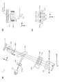
図1(a)、(b)は、実施の形態に係る光ピックアップ装置1の光学系を示す図である。図1(a)は光学系を光ピックアップ装置1の表側から(y軸正方向に)見た場合の平面図、図1(b)は対物レンズアクチュエータ122周辺部分を側面側から見た内部透視図、図1(c)は半導体レーザ101における発光部の配置状態を示す図である。なお、図1(a)〜(c)には、それぞれ、互いに直交する3次元座標軸が付記されている。これら座標軸のうち、x軸は、半導体レーザ101の出射方向に平行であり、y軸は、対物レンズ108の光軸に平行であり、z軸は、コリメータレンズ105の光軸に平行である。
1A and 1B are diagrams showing an optical system of an
図1(a)、(b)を参照して、光ピックアップ装置1は、半導体レーザ101と、回折格子102と、PBSミラー103と、1/4波長板104と、コリメータレンズ105と、レンズアクチュエータ106と、立ち上げミラー107と、対物レンズ108と、回折格子200と、非点収差板109と、光検出器110とを備える。
Referring to FIGS. 1A and 1B, an
半導体レーザ101は、波長400nm程度のレーザ光(以下、「BD光」という)と、波長650nm程度のレーザ光(以下、「DVD光」という)と、波長780nm程度のレーザ光(以下、「CD光」という)を同一方向に出射する。
The
図1(c)に示すように、半導体レーザ101は、一つのパッケージに、BD光、DVD光、CD光をそれぞれ出射する発光部101a、101b、101cを備える。発光部101b、101cは、基板101e上に間隔がw2となるように一体的に形成されている。発光部101aは、基板101eとは異なる基板101d上に、発光部101a、101bの間隔がw1(w1=w2)となるように形成されている。基板101d、101eは、サブマウント101f上に設置されている。発光部101a〜101cは、一直線上に並ぶように形成されている。本実施の形態において、半導体レーザ101以降の光学系は、その光軸がDVD光の光軸に整合するように調整されている。また、本実施の形態では、w1、w2は何れも90μmに設計されている。
As shown in FIG. 1C, the
ここで、発光部101aと、発光部101b、101cは、それぞれ、半導体製造プロセスによって、基板101d、101e上に形成される。このため、基板101dにおける発光部101aの位置精度と、基板101eにおける発光部101b、101cの位置精度は、十分に高められたものとなる。しかしながら、発光部が形成された基板101d、101eは、電極、接合層等を介して、サブマウント101f上に接合される。このため、サブマウント101fにおける基板101d、101eの位置精度は低くなる。以上の理由により、w2には、−1〜+1μm程度の誤差しか含まれないが、w1には、−10〜+10μm程度の誤差が生じてしまう。
Here, the
回折格子102は、半導体レーザ101から出射されたBD光、DVD光、CD光のうち主としてBD光をメインビームと2つのサブビームに分割する。回折格子102は、単純な3ビーム方式の回折格子であり、ディスク上におけるBD光の3つのビームの並び方向がディスクのトラックに平行な状態から僅かに傾くよう配置されている。回折格子102の入射面には、2ステップ型の回折溝102aが形成されている。回折溝102aは、いわゆるディファレンシャルプッシュプル法に基づくトラッキングエラー信号を生成可能なように、所定の回折角にて、BD光を回折させる。なお、DVD光とCD光も回折格子102による回折作用を受けるが、これら光のサブビームの強度は、極めて小さくなっている。回折格子102は、1/2波長板と回折格子の複合素子である。
The
PBSミラー103は、回折格子102側から入射されたレーザ光を反射する。PBSミラー103は、入射面と出射面が正方形の輪郭を有する薄板状の平行平板となっており、その入射面に、偏光膜が形成されている。回折格子102は、BD光、DVD光、CD光の偏光方向がPBSミラー103に対してS偏光となるように配置されている。
The
1/4波長板104は、PBSミラー103によって反射されたレーザ光を円偏光に変換するとともに、ディスクからの反射光を、ディスクへ向かうときの偏光方向に直交する直線偏光に変換する。これにより、ディスクによって反射されたレーザ光はPBSミラー103を透過して光検出器110へと導かれる。
The quarter-
コリメータレンズ105は、PBSミラー103によって反射されたレーザ光を平行光に変換する。レンズアクチュエータ106は、1/4波長板104とコリメータレンズ105を、コリメータレンズ105の光軸方向に駆動する。コリメータレンズ105が移動されることにより、レーザ光に生じる収差が補正される。
The
立ち上げミラー107は、コリメータレンズ105側から入射されたレーザ光を対物レンズ108に向かう方向(y軸負方向)に反射する。対物レンズ108は、ホルダ121に保持され、ホルダ121は、対物レンズアクチュエータ122によって、フォーカス方向(y軸方向)およびトラッキング方向(ディスクのラジアル方向)に駆動される。このようにホルダ121が駆動されることにより、対物レンズ108が、フォーカス方向およ
びトラッキング方向に駆動される。
The rising
なお、コリメータレンズ105側から立ち上げミラー107に入射するレーザ光の光軸は、ディスクのラジアル方向に対して67.5度傾いている。また、立ち上げミラー107からディスクに向かうBD光のメインビームと2つのサブビームの並び方向は、ディスクのタンジェンシャル方向から僅かにずれた方向と一致している。
The optical axis of the laser light incident on the rising
ディスクからの反射光は、1/4波長板104によりPBSミラー103に対してP偏光となる直線偏光に変換される。これにより、ディスクからの反射光は、PBSミラー103を透過する。
The reflected light from the disk is converted into linearly polarized light that becomes P-polarized light with respect to the
回折格子200は、いわゆる2ステップ型の回折溝を有する。すなわち、回折格子200に形成された回折溝は、一つの底面を有する矩形状の溝からなっている。回折格子200の回折溝は、BD光に対しては0次の回折効率が高くなり、CD光とDVD光に対しては1次の回折効率が高くなるよう、深さが設計されている。回折格子200は、回折方向がx軸方向に平行となるように配置される。回折格子200の構成は、追って、図3(a)を参照して詳述する。
The
DVD光が回折格子200に入射すると、BD光の光軸に近づく方向(x軸負方向)に回折される1次回折光と、BD光の光軸から離れる方向(x軸正方向)に回折される1次回折光が生じる。同様に、CD光が回折格子200に入射すると、BD光の光軸に近づく方向(x軸負方向)に回折される1次回折光と、BD光の光軸から離れる方向(x軸正方向)に回折される1次回折光が生じる。以下では、BD光の光軸に近づく方向(x軸負方向)に回折される1次回折光を「+1次回折光」と表し、BD光の光軸から離れる方向(x軸正方向)に回折される1次回折光を「−1次回折光」と表す。
When DVD light enters the
非点収差板109は、平行平板であり、BD光、DVD光、CD光の光軸に対して45度傾くように配置されている。これにより、非点収差板109に収束状態で入射するBD光、DVD光、CD光に対して、非点収差が導入される。なお、PBSミラー103は、平行平板であり、且つ、BD光、DVD光、CD光の光軸に対して傾いて配置されているため、各光には、PBSミラー103によっても非点収差が導入される。非点収差板109は、自身が導入する非点収差とPBSミラー103によって導入される非点収差とによって、各光に適正な非点収差が導入されるよう、厚み、屈折率、傾き方向が調整されている。
The
光検出器110の受光面は、xy平面に平行であり、かかる受光面上の、BD光、DVD光、CD光が照射される位置に、4分割センサが配置されている。光検出器110のセンサレイアウトについては、追って、図2(b)を参照して説明する。
The light receiving surface of the
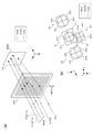
図2(a)は、回折格子200による回折作用を説明する図である。なお、図2(a)では、回折格子200と光検出器110の受光面との間に配される非点収差板109が、便宜上、図示省略されている。
FIG. 2A is a view for explaining the diffraction action by the
BD光、DVD光、CD光は、この順に、x軸正方向に並んだ状態で回折格子200に入射する。回折格子200に入射するBD光は、半導体レーザ101の直後に配された回折格子102によって、メインビームとサブビームに分割されている。BD光のメインビームとサブビームのビームの並び方向は、ディスクのタンジェンシャル方向から僅かにずれた方向に対応する方向となっており、回折格子200の回折方向(x軸方向)に垂直な方向に対して僅かに傾いている。
The BD light, the DVD light, and the CD light are incident on the
回折格子200に入射するBD光の3つのビームは、回折格子200により略回折されず、回折格子200をそのまま透過する。一方、DVD光とCD光は、回折格子200の回折作用によりx軸負方向に曲げられる。図2(a)では、BD光の0次以外の回折光と、DVD光とCD光の+1次以外の回折光は、便宜上、図示されていない。
The three beams of BD light incident on the
回折格子200により回折されたDVD光の+1次回折光は、光検出器110の受光面上において、BD光のメインビームの0次回折光と重なる。こうして、BD光のメインビームの光軸と、DVD光の光軸が、受光面上において一致する。
The + 1st order diffracted light of the DVD light diffracted by the
図2(b)は、光検出器110の受光面上に配される4分割センサS1〜S4を示す図である。なお、図2(b)は、光検出器110を裏面から(z軸負方向に)見た場合の4分割センサS1〜S4を示している。
FIG. 2B is a diagram showing the four-divided sensors S <b> 1 to S <b> 4 arranged on the light receiving surface of the
4分割センサS1は、BD光のメインビームの0次回折光とDVD光の+1次回折光を受光し、4分割センサS2、S3は、BD光の2つのサブビームの0次回折光を受光する。また、4分割センサS4は、CD光の+1次回折光を受光する。4分割センサS1〜S3は、これら3つの4分割センサの並び方向が、図2(a)に示すBD光の3つのビームの並び方向に一致するよう傾いて配置されている。4分割センサS4は、発光部101a〜101cの並び方向と同じ方向、すなわち、光検出器110の受光面上においてx軸方向に、4分割センサS1と隣り合うように配置される。
The 4-split sensor S1 receives the 0th-order diffracted light of the main beam of the BD light and the + 1st-order diffracted light of the DVD light, and the 4-split sensors S2 and S3 receive the 0th-order diffracted light of the two sub beams of the BD light. The quadrant sensor S4 receives + 1st order diffracted light of CD light. The four-divided sensors S1 to S3 are arranged so as to be inclined so that the arrangement direction of these three four-divided sensors matches the arrangement direction of the three beams of BD light shown in FIG. The quadrant sensor S4 is arranged adjacent to the quadrant sensor S1 in the same direction as the arrangement direction of the
4分割センサS1〜S4は、それぞれ、センサS11〜S14と、センサS21〜S24と、センサS31〜S34と、センサS41〜S44から構成されている。図2(b)において、4分割センサS1〜S3の並び方向をY軸方向とし、Y軸方向に垂直な方向をX軸方向とすると、X軸方向とY軸方向は、それぞれ、ディスクのラジアル方向に対応する方向と、ディスクのタンジェンシャル方向に対応する方向から僅かにずれた方向に対応する方向となる。 The four-divided sensors S1 to S4 are composed of sensors S11 to S14, sensors S21 to S24, sensors S31 to S34, and sensors S41 to S44, respectively. In FIG. 2B, when the arrangement direction of the four-divided sensors S1 to S3 is the Y-axis direction, and the direction perpendicular to the Y-axis direction is the X-axis direction, the X-axis direction and the Y-axis direction are respectively radial of the disc. A direction corresponding to the direction and a direction corresponding to a direction slightly shifted from the direction corresponding to the tangential direction of the disk.
4分割センサS1、S4の輪郭は、正方形のX軸方向の幅が縮められた形状であり、4分割センサS2、S3の輪郭は、正方形の角が落とされた形状である。4分割センサS1〜S4の分割線は、X軸方向とY軸方向に一致するよう構成される。4分割センサS1〜S4を構成する各センサからの出力により、再生RF信号、フォーカスエラー信号、トラッキングエラー信号が生成される。 The outlines of the quadrant sensors S1 and S4 are shapes in which the width of the square in the X-axis direction is reduced, and the outlines of the quadrant sensors S2 and S3 are shapes in which square corners are dropped. The dividing lines of the four-divided sensors S1 to S4 are configured to coincide with the X-axis direction and the Y-axis direction. A reproduction RF signal, a focus error signal, and a tracking error signal are generated by outputs from the respective sensors constituting the four-divided sensors S1 to S4.
DVD光の+1次回折光の光軸とCD光の+1次回折光の光軸との間隔は、回折格子200からz軸正方向に進むにつれて、図1(c)に示す発光部101b、101cの間隔w2から徐々に小さくなる。このため、4分割センサS1の中心と4分割センサS4の中心との間隔は、w2よりも小さいw3となっている。また、4分割センサS1〜S4に投影されるトラックの回折像の方向は、PBSミラー103と非点収差板109とによって導入される非点収差作用により、X軸に平行となっている。
The distance between the optical axis of the + 1st order diffracted light of the DVD light and the optical axis of the + 1st order diffracted light of the CD light is the distance between the light emitting
ここで、4分割センサS1の中心と4分割センサS4の中心との間のx軸方向の距離w3は、図1(c)に示す間隔w1、w2の設計値(ここでは90μm)に基づいて設定されている。しかしながら、上記のように、間隔w1には、±10μm程度の誤差が生じ得る。このため、かかる誤差に応じて回折格子200のz軸方向の位置を調整する必要がある。また、光検出器110上の各レーザ光の照射位置が、図2(b)に示すように適正な位置となるよう、回折格子102と光検出器110の位置も調整する必要がある。回折格子102、200と光検出器110の位置調整については、追って、図5を参照して説明する。
Here, the distance w3 in the x-axis direction between the center of the quadrant sensor S1 and the center of the quadrant sensor S4 is based on the design values (here, 90 μm) of the intervals w1 and w2 shown in FIG. Is set. However, as described above, an error of about ± 10 μm may occur in the interval w1. For this reason, it is necessary to adjust the position of the
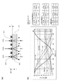
図3(a)は、図2(a)に示す回折格子200をx−z平面に平行な面で切断したときの断面図を模式的に示す図である。
FIG. 3A is a diagram schematically showing a cross-sectional view when the
回折格子200は、一つの底面を有する矩形状の回折溝201を備えている。回折溝201の深さはdである。すなわち、回折格子200は、図1(a)に示す回折格子102と同様、2ステップ型の回折格子である。回折格子200の入射面には、y軸方向に直線状に延びる複数の回折溝201が一定のピッチで形成されている。
The
なお、回折溝201は、ガラス基板202の上面に、SiO2からなる突部203を形成することにより形成される。突部203は、ガラス基板202の上面にSiO2層を形成した後、SiO2層をエッチングすることにより形成される。この構成は、現在、2ステップ型の回折格子に一般的に用いられるものである。
The
図3(b)は、回折溝201の深さdを変えたときの回折格子200の回折効率を示す図である。図3(b)の左側には、回折溝201のピッチと、各光に対するガラス基板202の屈折率と、各光に対する突部203の屈折率(SiO2の屈折率)を、図3(b)の右側に示すように設定したときのシミュレーション結果が示されている。なお、BD光、DVD光、CD光の波長は、それぞれ、405nm、660nm、785nmに設定されており、突部203のx軸方向の幅と回折溝201のx軸方向の幅は等しく設定されている。
FIG. 3B is a diagram showing the diffraction efficiency of the
半導体レーザ101において、BD光の発光パワーは、DVD光およびCD光に比べて弱い。このため、回折格子200は、BD光の0次の回折効率がDVD光およびCD光の+1次の回折効率よりも高くなるよう設定される。通常、BD光に対する回折効率は、90%程度であるのが望ましい。
In the
図3(b)の矢印の値(862nm)に回折溝201の深さdを設定することにより、図3(b)の右側の表に示すように、BD光の0次の回折効率を97%とすることができ、DVD光とCD光の+1次の回折効率を、それぞれ、35%、40%に設定することができる。このように、2ステップ型の単純形状かつ安価な回折格子200によっても、各光に対して望ましい回折効率を実現することができる。
By setting the depth d of the
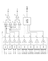
図4は、光検出器110内の信号処理回路110aの回路構成と、信号処理回路110aに接続される回路構成を示す図である。
FIG. 4 is a diagram illustrating a circuit configuration of the
信号処理回路110aは、8つのセレクタSL1〜SL8と、8つのアンプA1〜A8と、8つの出力端子T1〜T8を備えている。この他、信号処理回路110aは、制御回路を備えており、この制御回路によって、セレクタSL1〜SL8が制御され、また、アンプA1〜A8のゲインが調整される。なお、S11〜S14、S21〜S24、S31〜S34、S41〜S44は、それぞれ、図2(b)に示す各センサからの出力信号である。各センサからの信号は、それぞれ、セレクタSL1〜SL8に入力される。
The
セレクタSL1〜SL4は、入力された信号の何れか一方をアンプA1〜A4に出力する。また、セレクタSL5〜SL8は、入力された信号のうち一つまたは複数を選択してアンプA5〜A8に出力する。セレクタSL5〜SL8が複数の入力信号を選択する場合、選択された信号は加算され、加算された信号が、それぞれ、アンプA5〜A8に出力される。アンプA1〜A8は、それぞれ、入力された信号を、制御回路により設定されたゲインで増幅して出力端子T1〜T8に出力する。 The selectors SL1 to SL4 output any one of the input signals to the amplifiers A1 to A4. The selectors SL5 to SL8 select one or more of the input signals and output them to the amplifiers A5 to A8. When the selectors SL5 to SL8 select a plurality of input signals, the selected signals are added and the added signals are output to the amplifiers A5 to A8, respectively. Each of the amplifiers A1 to A8 amplifies the input signal with a gain set by the control circuit and outputs the amplified signal to the output terminals T1 to T8.
信号処理回路110aには、トラッキングエラー信号TEを生成するための回路(加算
器11、12、減算器15)と、フォーカスエラー信号FEを生成するための回路(加算器13、14、減算器16)と、補償信号を生成するための回路(サブ信号演算回路17)が接続される。これらの回路は、光ピックアップ装置1が搭載される光ディスク装置側に装備されている。サブ信号演算回路17は、BD光をBDに照射する際に、BD光のサブビームを受光する4分割センサS2、S3からの信号に基づいて、フォーカスエラー信号FEおよびトラッキングエラー信号TEを補償するための信号を生成する。補償信号は、適宜、フォーカスエラー信号FEおよびトラッキングエラー信号TEに加算される。本実施の形態において、トラッキングサーボに用いられるトラッキングエラー信号は、ディファレンシャルプッシュプル法に基づいて生成される。
The
ここで、BD光が用いられる場合、セレクタSL1〜SL4は、それぞれ、4分割センサS1のセンサS11〜S14からの信号をアンプA1〜A4に出力するよう制御される。また、BD光が用いられる場合、セレクタSL5〜SL8は、それぞれ、4分割センサS2のセンサS21〜S24からの信号と、4分割センサS3のセンサS31〜S34からの信号の中から所定の信号を選択してアンプA5〜A8に出力するよう制御される。このように、BD光が用いられる場合の各セレクタの接続状態を、以下、「BDモード」と称する。 Here, when BD light is used, the selectors SL1 to SL4 are controlled to output signals from the sensors S11 to S14 of the quadrant sensor S1 to the amplifiers A1 to A4, respectively. When BD light is used, the selectors SL5 to SL8 respectively receive predetermined signals from the signals from the sensors S21 to S24 of the quadrant sensor S2 and the signals from the sensors S31 to S34 of the quadrant sensor S3. It is controlled to select and output to the amplifiers A5 to A8. In this way, the connection state of each selector when BD light is used is hereinafter referred to as “BD mode”.
DVD光が用いられる場合、セレクタSL1〜SL4は、それぞれ、4分割センサS1のセンサS11〜S14からの信号をアンプA1〜A4に出力するよう制御される。CD光が用いられる場合、セレクタSL1〜SL4は、それぞれ、4分割センサS4のセンサS41〜S44からの信号をアンプA1〜A4に出力するよう制御される。また、DVD光とCD光が用いられる場合、セレクタSL5〜SL8の選択状態は、それぞれ、セレクタSL5〜SL8の出力端子がハイインピーダンス状態となるよう設定される。このように、DVD光とCD光が用いられる場合の各セレクタの接続状態を、それぞれ、以下、「DVDモード」と「CDモード」と称する。 When DVD light is used, the selectors SL1 to SL4 are controlled to output signals from the sensors S11 to S14 of the quadrant sensor S1 to the amplifiers A1 to A4, respectively. When CD light is used, the selectors SL1 to SL4 are controlled to output signals from the sensors S41 to S44 of the four-divided sensor S4 to the amplifiers A1 to A4, respectively. When DVD light and CD light are used, the selection states of the selectors SL5 to SL8 are set so that the output terminals of the selectors SL5 to SL8 are in a high impedance state, respectively. In this way, the connection state of each selector when DVD light and CD light are used is hereinafter referred to as “DVD mode” and “CD mode”, respectively.
また、後述するように、光検出器110の位置調整時と、回折格子102の回転方向の位置調整時には、セレクタSL1〜SL4は、それぞれ、4分割センサS1のセンサS11〜S14からの信号をアンプA1〜A4に出力するよう制御される。また、この場合、セレクタSL5は、4分割センサS3のセンサS31、S34からの信号を選択してアンプA5に出力するよう制御され、セレクタSL6は、4分割センサS2のセンサS22、S23からの信号を選択してアンプA6に出力するよう制御され、セレクタSL7は、4分割センサS3のセンサS32、S33からの信号を選択してアンプA7に出力するよう制御され、セレクタSL8は、4分割センサS2のセンサS21、S24からの信号を選択してアンプA8に出力するよう制御される。この場合の各セレクタの接続状態を、以下、「テストモード1」と称する。
As will be described later, the selectors SL1 to SL4 amplify signals from the sensors S11 to S14 of the quadrant sensor S1 when adjusting the position of the
また、後述するように、光検出器110の回転方向の位置調整時には、セレクタSL1〜SL4は、それぞれ、4分割センサS1のセンサS11〜S14からの信号をアンプA1〜A4に出力するよう制御される。また、この場合、セレクタSL5は、4分割センサS2のセンサS23、S24からの信号を選択してアンプA5に出力するよう制御され、セレクタSL6は、4分割センサS3のセンサS33、S34からの信号を選択してアンプA6に出力するよう制御され、セレクタSL7は、4分割センサS2のセンサS21、S22からの信号を選択してアンプA7に出力するよう制御され、セレクタSL8は、4分割センサS3のセンサS31、S32からの信号を選択してアンプA8に出力するよう制御される。この場合の各セレクタの接続状態を、以下、「テストモード2」と称する。
As will be described later, when the position of the
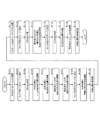
図5は、回折格子102、200と光検出器110の位置調整時の作業工程を示すフローチャートである。かかる位置調整は、光ピックアップ装置1の製造時に、所定の調整装
置を用いて行われる。この調整装置の入力端子は、図4に示した出力端子T1〜T8と接続される。
FIG. 5 is a flowchart showing an operation process when adjusting the positions of the
なお、以下の説明において、センサS11〜S14、S21〜S24、S31〜S34、S41〜S44の出力信号を、便宜上、それぞれ、S11〜S14、S21〜S24、S31〜S34、S41〜S44と表す。 In the following description, the output signals of the sensors S11 to S14, S21 to S24, S31 to S34, and S41 to S44 are respectively represented as S11 to S14, S21 to S24, S31 to S34, and S41 to S44 for convenience.
位置調整時には、まず、回折格子102、200と光検出器110が、初期位置に移動される。そして、BD用テストディスクが光ピックアップ装置1のターンテーブルに装着される(S101)。BD用テストディスクは、反りの無い形状を有する安定した基準ディスクであり、BD層を有している。
At the time of position adjustment, first, the
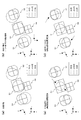
続いて、セレクタSL1〜SL8の接続状態がテストモード1に設定される(S102)。これにより、出力端子T1〜T4の出力信号は、それぞれ、S14、S11、S13、S12となり、出力端子T5〜T8の出力信号は、それぞれ、S31+S34、S22+S23、S32+S33、S21+S24となる。その後、発光部101aが点灯され、BD光が出射される(S103)。このとき、光検出器110上のBD光の分布と4分割センサS1〜S4の位置は、たとえば、図6(a)に示す状態となっている。
Subsequently, the connection state of the selectors SL1 to SL8 is set to the test mode 1 (S102). Thereby, the output signals of the output terminals T1 to T4 are S14, S11, S13, and S12, respectively, and the output signals of the output terminals T5 to T8 are S31 + S34, S22 + S23, S32 + S33, and S21 + S24, respectively. Thereafter, the
この状態で、光検出器110のx−y平面内の位置が調整される(S104)。具体的には、調整装置において、出力端子T1〜T4の出力信号に基づいて、以下の式(1)、(2)の演算が行われる。
In this state, the position of the
PosX={(S11+S12)−(S13+S14)}
/(S11+S12+S13+S14) …(1)
PosY={(S11+S14)−(S12+S13)}
/(S11+S12+S13+S14) …(2)
PosX = {(S11 + S12)-(S13 + S14)}
/ (S11 + S12 + S13 + S14) (1)
PosY = {(S11 + S14)-(S12 + S13)}
/ (S11 + S12 + S13 + S14) (2)
そして、上記式(1)、(2)により得られるPosX、PosYの値がゼロになるよう、光検出器110のx−y平面の位置が調整される。この場合、たとえば、PosX、PosYの値がモニタ上に表示され、作業者は、表示されたPosX、PosYの値がゼロになるよう、光検出器110のx−y平面内の位置を調整する。これにより、BD光のメインビームの0次回折光が、4分割センサS1の中央に位置付けられ、光検出器110上のBD光の分布は、たとえば、図6(b)に示す状態となる。
Then, the position of the
続いて、4分割センサS1から取得されるRF信号(SUM信号)が最大となるよう、光検出器110のz軸方向の位置が調整される(S105)。この場合、たとえば、RF信号の値がモニタ上に表示され、作業者は、表示されたRF信号の値が最大となるよう、光検出器110のz軸方向の位置を調整する。これにより、光検出器110の受光面上におけるBD光の0次回折光のビームが、適正な大きさとされ、光検出器110上のBD光の分布は、たとえば、図6(c)に示す状態となる。
Subsequently, the position of the
次に、回折格子102のx軸を中心とする回転方向の位置が調整される(S106)。具体的には、調整装置において、出力端子T1〜T8の出力信号に基づいて、以下の調整が行われる。
Next, the position of the
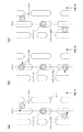
図8(a)〜(c)は、回折格子102の調整工程を例示的に示す図である。ここでは、回折格子102の位置調整前の状態において、BD光のメインビームと2つのサブビームが、トラックに対して図8(a)のように位置付けられている。なお、回折格子102の位置調整時には、トラッキングサーボがOFF状態に設定され、フォーカスサーボはO
N状態に設定される。
FIGS. 8A to 8C are diagrams exemplarily showing the adjustment process of the
Set to N state.
回折格子102の位置調整時には、まず、図8(b)のようにメインビームと2つのサブビームがトラック方向に平行に並ぶように、回折格子102の回転位置が調整される。この調整では、メインビームを受光する4分割センサS1からの信号と、走査方向においてメインビームの後ろ側にあるサブビーム(以下、「後行サブビーム」という)を受光する4分割センサS3からの信号がモニタされる。すなわち、4分割センサS1を構成するセンサS11〜S14から出力される信号の加算値(以下、「メインSUM信号」という)と、4分割センサS3を構成するセンサS31〜S34から出力される信号の加算値(以下、「サブSUM信号」という)がモニタされる。メインSUM信号は、調整装置において、図4に示す出力端子T1〜T4から出力される信号を加算して生成され、サブSUM信号は、調整装置において、図4に示す出力端子T5、T7から出力される信号を加算して生成される。
At the time of adjusting the position of the
この調整では、メインビームがトラック上の同期パターンに掛り始めたタイミングTmから後行サブビームがこの同期パターンに掛り始めたタイミングTsの時間差ΔTが、図8(b)のようにメインビームとサブビームがトラックに沿って並んだときの、メインビームと後行サブビームとの間のトラック方向の間隔に対応する時間T0に一致するよう、回折格子102の位置が調整される。
In this adjustment, the time difference ΔT between the timing Ts at which the subsequent sub beam starts to be applied to the synchronization pattern from the timing Tm at which the main beam has started to be applied to the synchronization pattern on the track is expressed as follows. The position of the
すなわち、メインビームが同期パターンを走査し始めると、メインSUM信号がハイレベルからローレベルへと立ち下がる。これに遅れて、後行サブビームが同期パターンを走査し始めると、サブSUM信号がハイレベルからローレベルへと立ち下がる。メインSUM信号の立ち下がりタイミングとサブSUM信号の立ち下がりタイミングの時間差が、上述の時間差ΔTに対応する。調整装置は、この時間差ΔTが上記時間T0に一致したことを、音、光あるいは画像等によって作業者が確認可能な構成を備えている。作業者は、回折格子102を微回動させ、時間差ΔTが時間T0に一致したことが確認される位置に、回折格子102を位置付ける。これにより、メインビームと2つのサブビームは、図8(b)のように、トラックに沿うように位置付けられる。なお、かかる調整工程は、たとえば、特開昭63−13128号公報に記載されている。
That is, when the main beam starts scanning the synchronization pattern, the main SUM signal falls from the high level to the low level. After this, when the subsequent sub beam starts scanning the synchronization pattern, the sub SUM signal falls from the high level to the low level. The time difference between the fall timing of the main SUM signal and the fall timing of the sub SUM signal corresponds to the above-described time difference ΔT. The adjusting device has a configuration in which an operator can confirm that the time difference ΔT coincides with the time T0 by sound, light, an image, or the like. The operator slightly rotates the
この調整が完了すると、次に、図8(c)に示すように、メインビームがトラック上に位置付けられ、且つ、2つのサブビームが、トラック間の位置に位置付けられるよう、回折格子102の回転位置が調整される。この調整では、調整装置において、メインビームと後行サブビームからそれぞれ得られるトラバース成分(RF信号のエンベロープ)をそれぞれオシロスコープのX軸入力とY軸入力として、リサージュ図形が表示される。メインビームと後行サブビームのトラバース成分は、それぞれ、メインSUM信号とサブSUM信号から取得される。そして、このリサージュ図形が位相差180度(π)の直線状となるように、回折格子102が微回転される。これにより、図8(c)のように、ディファレンシャルプッシュプル法に最適な3ビームの配置、すなわち、メインビームとサブビームの位相差がπとなり、2つのサブビームの位相差が2πとなる位置に、メインビームと2つのサブビームが配置される。
When this adjustment is completed, the rotational position of the
以上の工程により、回折格子102の回転位置の調整が完了する。
The adjustment of the rotational position of the
図5に戻り、続いて、回折格子102のx軸方向の位置が確認される(S107)。具体的には、調整装置において、出力端子T1〜T8の出力信号に基づいて、以下の式(4)、(5)の演算が行われる。
Returning to FIG. 5, subsequently, the position of the
SubΔY1={(S31+S34)−(S32+S33)}
/{(S31+S34)+(S32+S33)}
−{(S11+S14)−(S12+S13)}
/{(S11+S14)+(S12+S13)} …(3)
SubΔY2={(S21+S24)−(S22+S23)}
/{(S21+S24)+(S22+S23)}
−{(S11+S14)−(S12+S13)}
/{(S11+S14)+(S12+S13)} …(4)
SubΔY1 = {(S31 + S34) − (S32 + S33)}
/ {(S31 + S34) + (S32 + S33)}
-{(S11 + S14)-(S12 + S13)}
/ {(S11 + S14) + (S12 + S13)} (3)
SubΔY2 = {(S21 + S24) − (S22 + S23)}
/ {(S21 + S24) + (S22 + S23)}
-{(S11 + S14)-(S12 + S13)}
/ {(S11 + S14) + (S12 + S13)} (4)
そして、上記式(3)、(4)により得られるSubΔY1、SubΔY2の値が等しいかが確認される。通常、回折格子102がハウジングに設置されると、回折格子102のx軸方向の位置は適正なものとなり、BD光のメインビームと2つのサブビームとの間隔は互いに等しくなる。しかしながら、上記SubΔY1、SubΔY2の値が等しくない場合、BD光のメインビームと2つのサブビームとの間隔が互いに等しくないと判断され、再度、回折格子102の設置をやり直すなどの措置が取られる。回折格子102のx軸方向の位置が適正であると、次のステップに処理が進められる。
Then, it is confirmed whether the values of SubΔY1 and SubΔY2 obtained by the equations (3) and (4) are equal. Normally, when the
次に、セレクタSL1〜SL8の接続状態がテストモード2に設定される(S108)。これにより、出力端子T1〜T4の出力信号は、テストモード1と同様、それぞれ、S14、S11、S13、S12となる。一方、出力端子T5〜T8の出力信号は、それぞれ、S23+S24、S33+S34、S21+S22、S31+S32となる。
Next, the connection state of the selectors SL1 to SL8 is set to the test mode 2 (S108). Thereby, the output signals of the output terminals T1 to T4 are S14, S11, S13, and S12, respectively, as in the
続いて、4分割センサS1の中央(4分割センサS1の2つの分割線の交点)を中心とする光検出器110の回転方向の位置が調整される(S109)。具体的には、調整装置において、出力端子T5〜T8の出力信号に基づいて、以下の式(5)の演算が行われる。なお、以下の式(5)の(S23+S24+S31+S32)と(S21+S22+S33+S34)は、それぞれ、請求項に記載の「SA」と「SB」に相当する。
Subsequently, the position in the rotational direction of the
SubX={(S23+S24+S31+S32)
−(S21+S22+S33+S34)}
/{(S21+S22+S23+S24)
+(S31+S32+S33+S34)} …(5)
SubX = {(S23 + S24 + S31 + S32)
− (S21 + S22 + S33 + S34)}
/ {(S21 + S22 + S23 + S24)
+ (S31 + S32 + S33 + S34)} (5)
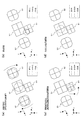
そして、上記式(5)により得られるSubXの値が0となるよう、4分割センサS1の中央を中心とする光検出器110の回転方向の位置が調整される。この場合、たとえば、SubXの値がモニタ上に表示され、作業者は、表示されたSubXの値がゼロになるよう、光検出器110の回転方向の位置を調整する。これにより、光検出器110の受光面上におけるBD光の2つのサブビームの0次回折光に、4分割センサS2、S3の中心が位置付けられ、光検出器110上BD光の分布と4分割センサS1〜S4は、たとえば、図7(a)に示す状態となる。
Then, the position in the rotation direction of the
こうして、BD光を用いた調整が終了すると、BD光の出射が停止される。そして、光検出器110が、光ピックアップ装置1のハウジングに対して仮接着される(S110)。
Thus, when the adjustment using the BD light is completed, the emission of the BD light is stopped. Then, the
次に、BD用テストディスクに替えて、DVD/CD用のテストディスクが、光ピックアップ装置1のターンテーブルに装着される(S111)。DVD/CD用テストディスクは、反りの無い形状を有する安定した基準ディスクであり、内周側にCD層を有し、外周側にDVD層を有するハイブリッドディスクである。DVD光が出射される場合は、DVD層が配された外周側の領域に光ピックアップ装置1が位置付けられ、CD光が出射される場合はCD層が配された内周側の領域に光ピックアップ装置1が位置付けられる。
Next, instead of the BD test disk, a DVD / CD test disk is mounted on the turntable of the optical pickup device 1 (S111). The DVD / CD test disc is a stable reference disc having a shape without warping, and is a hybrid disc having a CD layer on the inner peripheral side and a DVD layer on the outer peripheral side. When DVD light is emitted, the
続いて、セレクタSL1〜SL8の接続状態がCDモードに設定される(S112)。これにより、出力端子T1〜T4の出力信号は、それぞれ、S41〜S44となる。その後、発光部101cが点灯され、CD光が出射される(S113)。このとき、光検出器110上のCD光の分布は、たとえば、図7(b)に示す状態となっている。
Subsequently, the connection state of the selectors SL1 to SL8 is set to the CD mode (S112). Thereby, the output signals of the output terminals T1 to T4 become S41 to S44, respectively. Thereafter, the
この状態で、回折格子200のz軸方向の位置と、z軸を中心とする回転方向の位置が調整される(S114)。具体的には、調整装置において、出力端子T1〜T4の出力信号に基づいて、以下の式(6)、(7)の演算が行われる。
In this state, the position of the
PosX={(S41+S42)−(S43+S44)}
/(S41+S42+S43+S44) …(6)
PosY={(S41+S44)−(S42+S43)}
/(S41+S42+S43+S44) …(7)
PosX = {(S41 + S42)-(S43 + S44)}
/ (S41 + S42 + S43 + S44) (6)
PosY = {(S41 + S44)-(S42 + S43)}
/ (S41 + S42 + S43 + S44) (7)
そして、上記式(6)、(7)により得られるPosX、PosYの値がゼロになるよう、回折格子200のz軸方向の位置と、z軸を中心とする回転方向の位置が調整される。この場合、たとえば、PosX、PosYの値がモニタ上に表示され、作業者は、表示されたPosX、PosYの値がゼロになるよう、回折格子200のz軸方向の位置と回転方向の位置を調整する。これにより、CD光の+1次回折光が、4分割センサS4の中央に位置付けられ、光検出器110上のCD光の分布は、たとえば、図7(c)に示す状態となる。こうして、CD光を用いた調整が終了すると、CD光の出射が停止される。
Then, the position of the
次に、セレクタSL1〜SL8の接続状態がDVDモードに設定される(S115)。これにより、出力端子T1〜T4の出力信号は、それぞれ、S11〜S14となる。その後、発光部101bが点灯され、DVD光が出射される(S116)。このとき、光検出器110上のDVD光の分布は、たとえば、図7(d)に示す状態となっている。すなわち、4分割センサS1、S4の間隔は、回折格子200が適正に配置されたときの間隔に設定されているため、図7(c)に示すようにCD光が4分割センサS4の中央に位置付けられると、特に調整が行われることなく、通常、図7(d)に示すようにDVD光が4分割センサS1の中央に位置付けられる。
Next, the connection state of the selectors SL1 to SL8 is set to the DVD mode (S115). Thereby, the output signals of the output terminals T1 to T4 become S11 to S14, respectively. Thereafter, the
続いて、DVD光が4分割センサS1の位置が確認される(S117)。具体的には、調整装置において、出力端子T1〜T4の出力信号に基づいて、上記式(1)、(2)の演算が行われる。そして、上記式(1)、(2)により得られるPosX、PosYの値がゼロとなっているかが確認される。この場合、たとえば、PosX、PosYの値がモニタ上に表示され、作業者は、表示されたPosX、PosYの値がゼロとなっているかを確認する。これらの値が0となっていない場合は、DVD光の位置が適正でないと判断され、再度、回折格子200の設置をやり直すなどの措置が取られる。DVD光の位置が適正であると、次のステップに処理が進められる。
Subsequently, the position of the four-divided sensor S1 is confirmed by DVD light (S117). Specifically, in the adjustment device, calculations of the above formulas (1) and (2) are performed based on output signals from the output terminals T1 to T4. Then, it is confirmed whether the values of PosX and PosY obtained by the above formulas (1) and (2) are zero. In this case, for example, the values of PosX and PosY are displayed on the monitor, and the operator checks whether the displayed values of PosX and PosY are zero. If these values are not 0, it is determined that the position of the DVD light is not appropriate, and measures such as re-installation of the
次に、回折格子102、200が、光ピックアップ装置1のハウジングに対して接着される(S117)。また、光検出器110が、光ピックアップ装置1のハウジングに対して追加接着される(S118)。こうして、回折格子102、200と光検出器110の位置調整が完了する。
Next, the
<実施の形態の効果>
本実施の形態によれば、以下の効果が奏され得る。
<Effect of Embodiment>
According to the present embodiment, the following effects can be achieved.
回折格子102の回転方向の位置調整の際には、出力端子T1〜T8の出力信号、すな
わち、4分割センサS1、S3の出力信号を用いて、図8(a)〜(c)を参照して説明したとおり、回折格子102の回転方向の位置が調整される。
When adjusting the position of the
また、光検出器110の回転方向の位置調整の際には、出力端子T5〜T8の出力信号、すなわち、4分割センサS2、S3の出力信号を用いて、上記式(5)に示すSubXの演算が行われ、SubXの値が0となるよう光検出器110の回転方向の位置が調整される。
Further, when the position of the
このように、本実施の形態によれば、BD光のみを用いて、光検出器110の位置調整が全て行われる。すなわち、回折格子102の位置調整によりBD光のメインビームとサブビームが適正に並ぶよう位置付けられ、これらビームの並びを基準として、光検出器110の回転位置調整が行われる。本実施の形態によれば、調整装置に対して基準ディスクの差替えを行うことなく、簡便な作業により、光検出器110の位置調整を全て完了することができる。
Thus, according to the present embodiment, all the position adjustments of the
また、回折格子102、200と光検出器110の位置調整は、所定の調整装置を用いて行われ、調整装置の入力端子は、図4に示した出力端子T1〜T8と接続される。このとき、センサS11〜S14、S21〜S24、S31〜S34、S41〜S44のうち、上記式(1)〜(7)の演算および図8(a)〜(c)で示した調整に必要なセンサの出力信号が、図4に示すセレクタSL1〜SL8により選択され、出力端子T1〜T8に出力される。これにより、調整装置の入力端子が、出力端子T1〜T8と接続されるだけで、回折格子102、200と光検出器110の位置調整に必要な演算を容易に行うことができる。
Further, the position adjustment of the
以上、本発明の実施の形態について説明したが、本発明は、上記実施の形態に何ら制限されるものではなく、また、本発明の実施の形態も上記以外に種々の変更が可能である。 Although the embodiments of the present invention have been described above, the present invention is not limited to the above-described embodiments, and various modifications other than those described above can be made to the embodiments of the present invention.
たとえば、上記実施の形態では、BD光の発光部101aとCD光の発光部101cがDVD光の発光部101bを挟むように、半導体レーザ101が構成されたが、発光部101a〜101cの並び順は、他の順序に変更されても良く、たとえば、BD光の発光部101aとDVD光の発光部101bがCD光の発光部101cを挟むように、半導体レーザ101が構成されても良い。
For example, in the above embodiment, the
なお、この並び順の場合、対物レンズ108に対する画角の制限が最も緩やかなCD光の発光部101cが3つの発光部101a〜101cの中央に位置付けられるため、現状の対物レンズ108の画角特性を考慮すると、この並び順は、必ずしも望ましい並び順とは言えない。すなわち、この並び順において、CD光の光軸を対物レンズ108の光軸に一致させると、BD光とDVD光の両方が所定の画角を持って対物レンズ108に入射することになり、BD光とDVD光の何れか一方の光軸を対物レンズ108の光軸に一致させると、他方のレーザ光は、大きな画角をもって対物レンズ108に入射することになる。こうなると、BD光またはDVD光に大きな収差が発生する惧れがある。
In the case of this arrangement order, the light-emitting
よって、対物レンズ108に対する画角特性を考慮すると、BD光の発光部101aとCD光の発光部101cがDVD光の発光部101bを挟むように、半導体レーザ101が構成されるのが望ましい。
Therefore, in consideration of the angle of view characteristics with respect to the
また、上記実施の形態では、コリメータレンズ105側から立ち上げミラー107に入射するレーザ光の光軸と、ディスクのタンジェンシャル方向との角度が67.5度であったが、この角度は、これに限定されるものではない。本発明は、他の構成による光学系を備える光ピックアップ装置にも、適宜、適用可能である。
In the above embodiment, the angle between the optical axis of the laser beam incident on the rising
また、上記実施の形態では、回折格子200のz軸方向の位置と回転方向の位置の調整は、セレクタSL1〜SL8の接続状態がCDモードとされ、CD光が4分割センサS4の中心に位置付けられるように行われた。しかしながら、これに限らず、回折格子200のz軸方向の位置と回転方向の位置の調整は、セレクタSL1〜SL8の接続状態がDVDモードとされ、DVD光が4分割センサS1の中心に位置付けられるように行われても良い。この場合、上記式(1)、(2)により得られるPosX、PosYの値がゼロとなるよう、回折格子200のz軸方向の位置と回転方向の位置が調整される。
In the above embodiment, the adjustment of the position of the
また、上記実施の形態における回折格子102の位置調整では、図8(b)に示すようにメインビームと2つのサブビームの並び方向がトラックに平行となるよう、回折格子102が調整された後、このリサージュ図形が位相差180度(π)の直線状となるように、回折格子102の回転位置が調整されたが、図8(b)に示す調整過程を経ずに、直接、リサージュ図形が位相差180度(π)の直線状となるように、回折格子102の回転位置が調整されても良い。
Further, in the position adjustment of the
また、上記実施の形態では、図8(b)の調整および図8(c)の調整の際に、センサS11〜S14からそれぞれ出力される信号の加算信号(メインSUM信号)と、センサS31〜S34からそれぞれ出力される信号の加算信号(サブSUM信号)とが参照されたが、図8(b)、(c)のようにメインビームと2つのサブビームが並ぶことが確認できれば、センサS11〜S14から出力される信号の1つと、センサS31〜S34からそれぞれ出力される信号の1つが参照されても良く、あるいは、センサS11〜S14から出力される信号の2つまたは3つの組合せと、センサS31〜S34からそれぞれ出力される信号の2つまたは3つの組合せが参照されても良い。 Further, in the above embodiment, during the adjustment in FIG. 8B and the adjustment in FIG. 8C, the addition signal (main SUM signal) of the signals output from the sensors S11 to S14 and the sensors S31 to S31, respectively. Reference is made to the sum signal (sub-SUM signal) of the signals output from S34. If it can be confirmed that the main beam and the two sub-beams are aligned as shown in FIGS. One of the signals output from S14 and one of the signals output from the sensors S31 to S34 may be referred to, or two or three combinations of the signals output from the sensors S11 to S14 and the sensor Reference may be made to two or three combinations of signals output from S31 to S34, respectively.
また、上記実施の形態では、図8(b)の調整および図8(c)の調整の際に、メインビームと後行サブビームとそれぞれ受光する4分割センサS1、S3の出力が用いられたが、メインビームと先行サブビームとそれぞれ受光する4分割センサS1、S2の出力が用いられても良く、また、適宜、2つのサブビームをそれぞれ受光する4分割センサS2、S3の出力が用いられても良い。 In the above embodiment, the outputs of the four-divided sensors S1 and S3 that receive the main beam and the trailing sub-beam, respectively, are used during the adjustment in FIG. 8B and the adjustment in FIG. 8C. The outputs of the four-divided sensors S1 and S2 that respectively receive the main beam and the preceding sub-beam may be used, and the outputs of the four-divided sensors S2 and S3 that respectively receive the two sub-beams may be used as appropriate. .
さらに、上記実施の形態では、回折格子102として、単純な3ビーム方式の回折格子が用いられたが、これに代えて、インライン方式の回折格子が用いられても良い。
Furthermore, in the above-described embodiment, a simple three-beam diffraction grating is used as the
この他、本発明の実施の形態は、特許請求の範囲に示された技術的思想の範囲内において、適宜、種々の変更が可能である。 In addition, the embodiment of the present invention can be variously modified as appropriate within the scope of the technical idea shown in the claims.
1 … 光ピックアップ装置
101 … 半導体レーザ(レーザ光源)
101a … 発光部(第1の発光部)
101b … 発光部(第2の発光部)
101c … 発光部(第3の発光部)
102 … 回折格子(第1の回折格子)
102a … 回折溝
110 … 光検出器
110a … 信号処理回路(信号演算回路)
200 … 回折格子(第2の回折格子)
S1 … 4分割センサ(第1の4分割センサ)
S11〜S14 センサ
S2 … 4分割センサ(第2の4分割センサ)
S21〜S24 センサ
S3 … 4分割センサ(第2の4分割センサ)
S31〜S34 センサ
S4 … 4分割センサ(第3の4分割センサ)
S41〜S44 センサ
SL1〜SL4 … セレクタ(第1のセレクタ)
SL5〜SL8 … セレクタ(第2のセレクタ)
DESCRIPTION OF
101a ... Light emitting part (first light emitting part)
101b ... Light emitting part (second light emitting part)
101c ... Light emitting part (third light emitting part)
102 ... Diffraction grating (first diffraction grating)
102a ...
200 ... diffraction grating (second diffraction grating)
S1 ... 4-part sensor (first 4-part sensor)
S11 to S14 sensor S2... Quadrant sensor (second quadrant sensor)
S21 to S24 sensor S3... Quadrant sensor (second quadrant sensor)
S31 to S34 sensor S4 ... 4-part sensor (third 4-part sensor)
S41 to S44 Sensors SL1 to SL4 ... Selector (first selector)
SL5 to SL8 ... selector (second selector)
Claims (9)
前記光ピックアップ装置は、
互いに異なる波長の第1、第2および第3のレーザ光をそれぞれ出射する第1、第2および第3の発光部が同一パッケージ上に直線状に配置されたレーザ光源と、
前記第1の発光部から出射された前記第1のレーザ光をメインビームと2つのサブビームに分割する第1の回折格子と、
前記第1のレーザ光に対応する第1のディスクによって反射された前記メインビームの反射光を受光する第1の4分割センサと、前記第1のディスクによって反射された前記2つのサブビームの反射光をそれぞれ受光する2つの第2の4分割センサとを有する光検出器と、を備え、
前記第1のレーザ光に対応する第1の基準ディスクに対して前記第1のレーザ光を照射したときに、前記第1の4分割センサと前記第2の4分割センサから出力される信号に基づいて、前記メインビームと前記2つのサブビームが前記第1の基準ディスク上のトラックに対して適正に位置付けられるよう、前記第1の回折格子の回転位置を調整する第1の調整工程と、
前記第1の調整工程の後に、前記第1の基準ディスクに対して前記第1のレーザ光を照射したときに、前記第2の4分割センサから出力される信号に基づいて、前記第1の4分割センサの2つの分割線の交点を中心とする前記光検出器の回転位置を調整する第2の調整工程と、を含む、
ことを特徴とする光ピックアップ装置における光検出器の位置調整方法。 In the method of adjusting the position of the photodetector in the optical pickup device,
The optical pickup device is:
A laser light source in which first, second, and third light emitting units that respectively emit first, second, and third laser beams having different wavelengths are arranged linearly on the same package;
A first diffraction grating that divides the first laser light emitted from the first light emitting unit into a main beam and two sub beams;
A first four-divided sensor that receives the reflected light of the main beam reflected by the first disk corresponding to the first laser light, and the reflected light of the two sub beams reflected by the first disk A photodetector having two second quadrant sensors that respectively receive
When the first laser beam is irradiated onto the first reference disk corresponding to the first laser beam, the signals output from the first four-divided sensor and the second four-divided sensor A first adjustment step of adjusting a rotational position of the first diffraction grating so that the main beam and the two sub-beams are properly positioned with respect to the track on the first reference disk;
After the first adjustment step, the first reference disk is irradiated with the first laser beam, based on a signal output from the second four-divided sensor, A second adjustment step of adjusting the rotational position of the photodetector around the intersection of two parting lines of the four-part sensor.
A method for adjusting the position of a photodetector in an optical pickup device.
前記第1の回折格子は、ディファレンシャルプッシュプル法に基づいてトラッキングエラー信号を生成するための回折溝を備え、
前記第1の調整工程は、前記メインビームと前記2つのサブビームが前記第1の基準ディスク上においてディファレンシャルプッシュプル法に適する配置となるように、実行される、
ことを特徴とする光ピックアップ装置における光検出器の位置調整方法。 The method for adjusting the position of a photodetector in the optical pickup device according to claim 1,
The first diffraction grating includes a diffraction groove for generating a tracking error signal based on a differential push-pull method,
The first adjustment step is executed such that the main beam and the two sub beams are arranged on the first reference disk so as to be suitable for a differential push-pull method.
A method for adjusting the position of a photodetector in an optical pickup device.
前記2つの第2の4分割センサをそれぞれ前記第1の4分割センサと前記第2の4分割センサの並び方向に平行な分割線によって2つのセンサの組に分割し、これらセンサの組のうち、互いにたすき掛けの位置にある2つのセンサの組から出力される信号を加算した加算信号をそれぞれSA、SBとしたとき、前記第2の調整工程は、以下の算出式により求まる信号値がゼロとなるように、実行される、
ことを特徴とする光ピックアップ装置における光検出器の位置調整方法。
SubX=(SA−SB)/(SA+SB) In the optical pickup apparatus position adjusting method according to claim 1 or 2,
The two second four-divided sensors are divided into two sensor sets by dividing lines parallel to the arrangement direction of the first four-divided sensor and the second four-divided sensor, respectively. When the addition signals obtained by adding the signals output from the pair of two sensors in the position where they are overlaid with each other are SA and SB, the signal value obtained by the following calculation formula is zero in the second adjustment step. To be executed,
A method for adjusting the position of a photodetector in an optical pickup device.
SubX = (SA−SB) / (SA + SB)
前記光検出器は、前記第3のレーザ光に対応する第3のディスクによって反射された前記第3のレーザ光の反射光を受光する第3の4分割センサを備え、
前記光ピックアップ装置は、前記第2のレーザ光に対応する第2のディスクによって反射された前記第2のレーザ光の反射光を前記第1の4分割センサに導くと共に、前記第3のレーザ光の前記反射光を前記第3の4分割センサに導く第2の回折格子をさらに備え、
前記第2の調整工程の後に、前記第2のレーザ光または前記第3のレーザ光に対応する基準ディスクに対して前記第2のレーザ光または前記第3のレーザ光を照射したときに、
前記第1の4分割センサまたは前記第3の4分割センサから出力される信号に基づいて、前記第2の回折格子の位置を調整する第3の調整工程をさらに含む、
ことを特徴とする光ピックアップ装置における光検出器の位置調整方法。 The method for adjusting the position of a photodetector in the optical pickup device according to any one of claims 1 to 3,
The photodetector includes a third quadrant sensor that receives reflected light of the third laser light reflected by a third disk corresponding to the third laser light,
The optical pickup device guides the reflected light of the second laser light reflected by the second disk corresponding to the second laser light to the first four-divided sensor, and the third laser light. A second diffraction grating that guides the reflected light to the third quadrant sensor,
After the second adjustment step, when the second laser light or the third laser light is irradiated to the reference disk corresponding to the second laser light or the third laser light,
A third adjustment step of adjusting a position of the second diffraction grating based on a signal output from the first four-divided sensor or the third four-divided sensor;
A method for adjusting the position of a photodetector in an optical pickup device.
前記第1の発光部から出射された前記第1のレーザ光をメインビームと2つのサブビームに分割する第1の回折格子と、
前記第1のレーザ光に対応する第1のディスクによって反射された前記メインビームの反射光を受光する第1の4分割センサと、前記第1のディスクによって反射された前記2つのサブビームの反射光をそれぞれ受光する2つの第2の4分割センサとを有する光検出器と、
前記光検出器から出力される信号から所定の信号を生成する信号演算回路と、を備え、
前記信号演算回路は、
前記第1の4分割センサの各センサから出力される信号のうち所定の信号を選択する第1のセレクタと、
前記第2の4分割センサの各センサから出力される信号のうち所定の信号を選択する複数の第2のセレクタと、を有し、
前記第1のセレクタと前記第2のセレクタは、
前記第1のレーザ光に対応する第1の基準ディスクに対して前記第1のレーザ光を照射しながら、前記メインビームと前記2つのサブビームが前記第1の基準ディスク上のトラックに対して適正に位置付けられるよう、前記第1の回折格子の回転位置を調整する際に用いられる第1の調整信号を出力する第1の選択モードと、
前記第1の基準ディスクに対して前記第1のレーザ光を照射しながら、前記第1の4分割センサの2つの分割線の交点を中心とする前記光検出器の回転位置を調整する際に用いられる第2の調整信号を出力する第2の選択モードと、を含む、
ことを特徴とする光ピックアップ装置。 A laser light source in which first, second, and third light emitting units that respectively emit first, second, and third laser beams having different wavelengths are arranged linearly on the same package;
A first diffraction grating that divides the first laser light emitted from the first light emitting unit into a main beam and two sub beams;
A first four-divided sensor that receives the reflected light of the main beam reflected by the first disk corresponding to the first laser light, and the reflected light of the two sub beams reflected by the first disk A photodetector having two second quadrant sensors that respectively receive
A signal arithmetic circuit that generates a predetermined signal from the signal output from the photodetector,
The signal arithmetic circuit is
A first selector that selects a predetermined signal from signals output from the sensors of the first four-divided sensor;
A plurality of second selectors for selecting a predetermined signal from signals output from the sensors of the second four-divided sensor;
The first selector and the second selector are:
While irradiating the first laser beam to the first reference disk corresponding to the first laser beam, the main beam and the two sub beams are appropriate for the track on the first reference disk. A first selection mode for outputting a first adjustment signal used when adjusting the rotational position of the first diffraction grating,
When adjusting the rotational position of the photodetector around the intersection of two dividing lines of the first four-divided sensor while irradiating the first laser beam to the first reference disk A second selection mode for outputting a second adjustment signal to be used,
An optical pickup device characterized by that.
前記第1の回折格子は、ディファレンシャルプッシュプル法に基づいてトラッキングエラー信号を生成するための回折溝を備え、
前記第1および第2のセレクタは、前記第1の選択モードにおいて、前記メインビームと前記2つのサブビームが前記第1の基準ディスク上においてディファレンシャルプッシュプル法に適する配置となることを確認するための信号が生成されるように、前記第1および第2の4分割センサからの信号を組み合わせて加算した信号を出力する、
ことを特徴とする光ピックアップ装置。 The optical pickup device according to claim 5,
The first diffraction grating includes a diffraction groove for generating a tracking error signal based on a differential push-pull method,
In the first selection mode, the first and second selectors confirm that the main beam and the two sub beams are arranged on the first reference disk so as to be suitable for the differential push-pull method. Outputting a signal obtained by combining and adding the signals from the first and second quadrant sensors so that a signal is generated;
An optical pickup device characterized by that.
前記2つの第2の4分割センサをそれぞれ前記第1の4分割センサと前記第2の4分割センサの並び方向に平行な分割線によって2つのセンサの組に分割し、これらセンサの組のうち、互いにたすき掛けの位置にある2つのセンサの組から出力される信号を加算した加算信号をそれぞれSA、SBとしたとき、
前記第1および第2のセレクタは、前記第1の選択モードにおいて、後段の回路において前記加算信号SA、SBが生成されるように、前記第1および第2の4分割センサからの信号を組み合わせて加算した信号を出力する、
ことを特徴とする光ピックアップ装置。 The optical pickup device according to claim 5 or 6,
The two second four-divided sensors are divided into two sensor sets by dividing lines parallel to the arrangement direction of the first four-divided sensor and the second four-divided sensor, respectively. When the addition signals obtained by adding the signals output from the set of two sensors in the position where they cross each other are SA and SB,
The first and second selectors combine signals from the first and second quadrant sensors so that the addition signals SA and SB are generated in a subsequent circuit in the first selection mode. Output the added signal,
An optical pickup device characterized by that.
前記光検出器は、前記第3のレーザ光に対応する第3のディスクによって反射された前記第3のレーザ光の反射光を受光する第3の4分割センサを備え、
前記第2のレーザ光に対応する第2のディスクによって反射された前記第2のレーザ光の反射光を前記第1の4分割センサに導くと共に、前記第3のレーザ光の前記反射光を前記第3の4分割センサに導く第2の回折格子をさらに備え、
前記第1のセレクタは、さらに、第3の4分割センサの各センサから出力される信号のうち所定の信号を選択するよう構成され、
前記第1および第2のセレクタは、前記第2のディスクまたは前記第3のディスクに対応する基準ディスクに対して前記第2のレーザ光または前記第3のレーザ光を照射しながら、前記第1の4分割センサまたは前記第3の4分割センサから出力される信号に基づいて、前記第2の回折格子の位置を調整する際に用いられる第3の調整信号を出力する第3の選択モードをさらに含む、
ことを特徴とする光ピックアップ装置。 The optical pickup device according to any one of claims 5 to 7,
The photodetector includes a third quadrant sensor that receives reflected light of the third laser light reflected by a third disk corresponding to the third laser light,
The reflected light of the second laser light reflected by the second disk corresponding to the second laser light is guided to the first four-divided sensor, and the reflected light of the third laser light is A second diffraction grating leading to the third quadrant sensor;
The first selector is further configured to select a predetermined signal from signals output from the sensors of the third quadrant sensor,
The first and second selectors irradiate the second laser light or the third laser light to a reference disk corresponding to the second disk or the third disk, and And a third selection mode for outputting a third adjustment signal used when adjusting the position of the second diffraction grating based on a signal output from the four-divided sensor or the third four-divided sensor. In addition,
An optical pickup device characterized by that.
前記第1、第2および第3のディスクは、それぞれ、BD、DVDおよびCDである、ことを特徴とする光ピックアップ装置。 The optical pickup device according to any one of claims 5 to 8,
The optical pickup device, wherein the first, second and third discs are BD, DVD and CD, respectively.
Priority Applications (1)
| Application Number | Priority Date | Filing Date | Title |
|---|---|---|---|
| JP2012256700A JP2014106983A (en) | 2012-11-22 | 2012-11-22 | Optical detector position adjustment method in optical pickup device, and optical pickup device |
Applications Claiming Priority (1)
| Application Number | Priority Date | Filing Date | Title |
|---|---|---|---|
| JP2012256700A JP2014106983A (en) | 2012-11-22 | 2012-11-22 | Optical detector position adjustment method in optical pickup device, and optical pickup device |
Publications (1)
| Publication Number | Publication Date |
|---|---|
| JP2014106983A true JP2014106983A (en) | 2014-06-09 |
Family
ID=51028333
Family Applications (1)
| Application Number | Title | Priority Date | Filing Date |
|---|---|---|---|
| JP2012256700A Pending JP2014106983A (en) | 2012-11-22 | 2012-11-22 | Optical detector position adjustment method in optical pickup device, and optical pickup device |
Country Status (1)
| Country | Link |
|---|---|
| JP (1) | JP2014106983A (en) |
-
2012
- 2012-11-22 JP JP2012256700A patent/JP2014106983A/en active Pending
Similar Documents
| Publication | Publication Date | Title |
|---|---|---|
| JP4610628B2 (en) | Optical pickup device and focus adjustment method | |
| CN101252006B (en) | Optical head and optical information recording and reproducing device | |
| JP5173656B2 (en) | Optical pickup device | |
| JP4684341B2 (en) | Optical pickup device, optical disk device, and focus adjustment method | |
| JP2011008852A (en) | Optical pickup device | |
| JP4722190B2 (en) | Optical pickup device and optical disk device | |
| JP2005327387A (en) | Optical pickup apparatus | |
| JP5227930B2 (en) | Optical pickup device | |
| JP2006120189A (en) | Optical pickup apparatus | |
| US8400901B2 (en) | Optical pickup device | |
| JP4222988B2 (en) | Optical pickup device and optical disk device | |
| JP2013222484A (en) | Position adjustment method of photodetector and optical pickup device | |
| US8432783B2 (en) | Optical pickup device and position adjusting method for light separating element | |
| US8331211B2 (en) | Optical pickup device | |
| JP2015172985A (en) | optical pickup device | |
| JP2011034623A (en) | Optical pickup device and optical disk device | |
| JP2014022012A (en) | Fitting structure of optical element, and optical pickup device | |
| US8264937B2 (en) | Optical pickup device | |
| JP2006099941A (en) | Optical pickup apparatus | |
| JP5173868B2 (en) | Optical pickup device and optical disk device | |
| JP2008047195A (en) | Optical pickup | |
| CN102881298B (en) | Optical pickup apparatus | |
| CN102651223A (en) | Optical head | |
| JP2013161499A (en) | Optical pickup device | |
| JP2015109117A (en) | Optical pickup device |