JP2014104256A - Game machine - Google Patents

Game machine Download PDF

Info

Publication number
JP2014104256A
JP2014104256A JP2012261009A JP2012261009A JP2014104256A JP 2014104256 A JP2014104256 A JP 2014104256A JP 2012261009 A JP2012261009 A JP 2012261009A JP 2012261009 A JP2012261009 A JP 2012261009A JP 2014104256 A JP2014104256 A JP 2014104256A
Authority
JP
Japan
Prior art keywords
game
game ball
inflow port
guide path
gaming machine
Prior art date
Legal status (The legal status is an assumption and is not a legal conclusion. Google has not performed a legal analysis and makes no representation as to the accuracy of the status listed.)
Pending
Application number
JP2012261009A
Other languages
Japanese (ja)
Inventor
Toshio Ogura
敏男 小倉
Kenji Fujiyoshi
健治 藤吉
Current Assignee (The listed assignees may be inaccurate. Google has not performed a legal analysis and makes no representation or warranty as to the accuracy of the list.)
Sankyo Co Ltd
Original Assignee
Sankyo Co Ltd
Priority date (The priority date is an assumption and is not a legal conclusion. Google has not performed a legal analysis and makes no representation as to the accuracy of the date listed.)
Filing date
Publication date
Application filed by Sankyo Co Ltd filed Critical Sankyo Co Ltd
Priority to JP2012261009A priority Critical patent/JP2014104256A/en
Publication of JP2014104256A publication Critical patent/JP2014104256A/en
Pending legal-status Critical Current

Links

Images

Landscapes

  • Pinball Game Machines (AREA)

Abstract

PROBLEM TO BE SOLVED: To provide a game machine capable of improving an interest even after a game ball entered a distribution device.SOLUTION: A game machine for performing a game by shooting a game ball P into a game area of a game board comprises: a distribution device 50 forming a first guide path 86 and a second guide path 87 for guiding the game ball P coming from an approach mouth 68, into a first area 81 and a second area 82; and a first inflow port 58a and a second inflow port 58b, into which the game ball P flows. The game machine is characterized in that the first inflow port 58a and the second inflow port 58b are disposed at positions on the back sides of the first guide path 86 and second guide path 87 in the distribution device 50.

Description

この発明は、遊技盤面の遊技領域に遊技球を発射することにより遊技が行われる遊技機に関する。   The present invention relates to a gaming machine in which a game is played by firing a game ball onto a game area on a game board surface.

遊技機は、遊技領域内に設けられた釘や役物等によって、遊技者が発射した遊技球の流路を様々に変化させることにより、遊技の興趣を向上させている。従来、遊技球の流路を変化させる役物として、遊技球の流路を複数の流路に振り分け可能な振分装置が知られている(例えば、特許文献1参照)。   The gaming machine improves the interest of the game by changing the flow path of the game ball launched by the player in various ways, such as with a nail or an accessory provided in the game area. 2. Description of the Related Art Conventionally, as an accessory that changes the flow path of a game ball, a sorting apparatus that can distribute the flow path of the game ball into a plurality of flow paths is known (see, for example, Patent Document 1).

特許文献1に記載の振分装置は、遊技領域を流下する遊技球が進入可能な進入口と、遊技球が流入可能な第1領域及び第2領域と、進入口から進入した遊技球を第1領域に向けて導く状態と第2領域に向けて導く状態とを実現可能であり、第1領域と第2領域とに遊技球を振り分ける振分け部材と、を有しており、振分け部材は、進入口から進入した遊技球の自重によって、遊技球を第1領域に向けて導く状態と、第2領域に向けて導く状態とを交互に実現している。特許文献1に記載の振分装置によれば、複雑な制御手段を要することなく、遊技球を第1領域と第2領域とに交互に振り分けることができるとされている。   The distribution device described in Patent Document 1 has an entrance into which a game ball flowing down the game area can enter, a first area and a second area into which the game ball can flow, and a game ball that has entered from the entrance into the first area. A state of guiding toward the first region and a state of guiding toward the second region can be realized, and includes a distribution member that distributes the game balls to the first region and the second region. A state in which the game ball is guided toward the first region and a state in which the game ball is guided toward the second region are alternately realized by the dead weight of the game ball that has entered from the entrance. According to the distribution device described in Patent Document 1, it is said that game balls can be alternately distributed to the first region and the second region without requiring complicated control means.

特開2010−104564号公報JP 2010-104564 A

しかし、従来技術の振分装置を備えた遊技機にあっては、遊技者は、進入口から振分装置に遊技球が進入した時点で、遊技球が第1領域および第2領域のいずれかに振り分けられるかが予測可能である。しかも、遊技球が振分け部材によって振り分けられた後は、第1領域および第2領域のいずれかに必ず導かれる。このため、振分装置に進入した後の遊技球の動きに遊技者の注目を効果的に集めているとは言い難く、遊技の興趣の向上に改善の余地があった。   However, in a gaming machine equipped with a sorting device of the prior art, when a game ball enters the sorting device from the entrance, the game ball is either in the first area or the second area. Can be predicted. In addition, after the game ball is distributed by the distribution member, it is always guided to either the first area or the second area. For this reason, it is difficult to say that the player's attention is effectively gathered in the movement of the game ball after entering the sorting apparatus, and there is room for improvement in improving the interest of the game.

そこで本発明は、上述した事情に鑑みてなされたものであって、振分装置に遊技球が進入した後であっても、興趣を向上できる遊技機を提供することを目的とする。   Therefore, the present invention has been made in view of the above-described circumstances, and an object thereof is to provide a gaming machine that can improve interest even after a game ball has entered a sorting device.

上記の課題を解決するため、本発明の請求項1に記載の遊技機は、遊技盤面の遊技領域に遊技球を発射することにより遊技が行われる遊技機であって、進入口から進入した前記遊技球を第1領域と第2領域とに誘導する第1誘導路および第2誘導路を形成する振分装置と、前記遊技領域に設けられる開口から構成され、前記遊技球が流入する流入口と、を備え、前記流入口は、前記振分装置における前記第1誘導路および前記第2誘導路の背面側の位置に設けられていることを特徴としている。   In order to solve the above-described problems, a gaming machine according to claim 1 of the present invention is a gaming machine in which a game is played by firing a game ball in a game area of a game board surface, and the game machine that has entered from an entrance A distribution device that forms a first guiding path and a second guiding path for guiding the game ball to the first region and the second region, and an opening provided in the game region, into which the game ball flows The inflow port is provided at a position on the back side of the first guiding path and the second guiding path in the sorting device.

本発明によれば、第1誘導路および第2誘導路の背面側の位置に、遊技球が流入する流入口が設けられているので、遊技球は、進入口から振分装置内に進入した後、第1誘導路および第2誘導路のいずれかを通過中に、遊技球が流入口に流入するか、もしくは第1領域および第2領域のいずれかに導かれる。このため、遊技球が進入口から振分装置内に進入し、第1誘導路および第2誘導路のいずれかに振り分けられた後であっても、遊技球の動きに遊技者の注目を集めることができるので、遊技の興趣を向上できる。   According to the present invention, since the inflow port into which the game ball flows is provided at a position on the back side of the first guide path and the second guide path, the game ball has entered the distribution device from the entrance. Thereafter, while passing through either the first guide path or the second guide path, the game ball flows into the inflow port or is guided to either the first area or the second area. For this reason, even after the game ball enters the sorting device from the entrance and is distributed to either the first guide path or the second guide path, the player's attention is drawn to the movement of the game ball. Can improve the interest of the game.

また、本発明の手段1に記載の遊技機は、請求項1に記載の遊技機であって、前記流入口は、前記第1誘導路および前記第2誘導路の背面側の位置にそれぞれ設けられていてもよい。   The gaming machine according to means 1 of the present invention is the gaming machine according to claim 1, wherein the inflow port is provided at a position on the back side of the first guiding path and the second guiding path, respectively. It may be done.

この場合、第1誘導路および第2誘導路のいずれの誘導路に振り分けられたかに関わらず、遊技球が流入口に流入する可能性がある。したがって、第1誘導路および第2誘導路のいずれの誘導路に振り分けられたかに影響されることなく、遊技球の動きに遊技者の注目を最後まで集めることができる。   In this case, the game ball may flow into the inflow port regardless of which one of the first guide path and the second guide path is assigned. Therefore, the player's attention can be gathered to the end of the movement of the game ball without being influenced by which of the first guide path and the second guide path.

また、本発明の手段2に記載の遊技機は、請求項1または手段1に記載の遊技機であって、前記第1誘導路の背面側の位置に設けられた前記流入口の直径と、前記第2誘導路の背面側の位置に設けられた前記流入口の直径とは、それぞれ略同一であってもよい。   Further, the gaming machine according to means 2 of the present invention is the gaming machine according to claim 1 or means 1, wherein the diameter of the inflow port provided at a position on the back side of the first guiding path, The diameters of the inflow ports provided at positions on the back side of the second guide path may be substantially the same.

この場合、第1誘導路および第2誘導路のいずれの誘導路に振り分けられたかに関わらず、同じ確率で遊技球が流入口に流入する可能性がある。したがって、第1誘導路および第2誘導路のいずれの誘導路に振り分けられたかに影響されることなく、遊技球の動きに遊技者の注目を最後まで集めることができる。   In this case, there is a possibility that the game ball flows into the inflow port with the same probability regardless of which one of the first taxiway and the second taxiway is assigned. Therefore, the player's attention can be gathered to the end of the movement of the game ball without being influenced by which of the first guide path and the second guide path.

また、本発明の手段3に記載の遊技機は、請求項1または手段1に記載の遊技機であって、前記第1誘導路の背面側の位置に設けられた前記流入口の直径と、前記第2誘導路の背面側の位置に設けられた前記流入口の直径とは、それぞれ異なっていてもよい。   Further, the gaming machine according to means 3 of the present invention is the gaming machine according to claim 1 or means 1, wherein the diameter of the inflow port provided at the position on the back side of the first guiding path, The diameter of the inflow port provided at the position on the back side of the second guiding path may be different from each other.

この場合、第1誘導路および第2誘導路のいずれの誘導路に振り分けられたかに関わらず、遊技球が流入口に流入する可能性を保持しつつ、第1誘導路および第2誘導路のいずれの誘導路に振り分けられたかによって、遊技球が流入口に流入する確率を異ならせることができる。したがって、遊技球の動きに遊技者の注目を最後まで集めることができる。   In this case, regardless of which one of the first taxiway and the second taxiway is assigned, the possibility that the game ball flows into the inflow port is maintained, and the first taxiway and the second taxiway The probability that the game ball flows into the inflow port can be made different depending on which guide path is assigned. Therefore, the player's attention can be gathered to the end of the movement of the game ball.

また、本発明の手段4に記載の遊技機は、請求項1または手段1から手段3のいずれかに記載の遊技機であって、前記流入口は、円形状に形成され、前記流入口の直径は、前記遊技球の直径と略同一か、前記遊技球の直径よりもわずかに大径になるように形成されていてもよい。   The gaming machine according to means 4 of the present invention is the gaming machine according to claim 1 or any one of means 1 to 3, wherein the inflow port is formed in a circular shape, The diameter may be formed to be substantially the same as the diameter of the game ball or slightly larger than the diameter of the game ball.

この場合、遊技球は、流入口に一度に複数個流入することができなくなり、一球ずつ流入することになる。したがって、遊技球が流入口に過剰に流入するのを抑制できる。   In this case, a plurality of game balls cannot flow into the inflow port at a time, and flow in one ball at a time. Therefore, it is possible to suppress an excessive flow of game balls into the inflow port.

また、本発明の手段5に記載の遊技機は、請求項1に記載の遊技機であって、前記流入口は、前記第1誘導路および前記第2誘導路の背面側の位置において、前記第1誘導路および前記第2誘導路に跨るように連続的に形成されていてもよい。   The gaming machine according to means 5 of the present invention is the gaming machine according to claim 1, wherein the inflow port is located at a position on the back side of the first guiding path and the second guiding path. It may be continuously formed so as to straddle the first guiding path and the second guiding path.

この場合、第1誘導路および第2誘導路のいずれの誘導路に振り分けられたかに関わらず、遊技球が流入口に流入した後、同一の流路で遊技球を導くことができる。   In this case, the game ball can be guided through the same flow path after the game ball flows into the inflow port regardless of which of the first guide path and the second guide path is assigned.

また、本発明の手段6に記載の遊技機は、請求項1、手段1または手段5に記載の遊技機であって、前記流入口は、長円形状に形成され、前記流入口の幅は、前記遊技球の直径と略同一か、前記遊技球の直径よりもわずかに広くなるように形成されていてもよい。   The gaming machine according to means 6 of the present invention is the gaming machine according to claim 1, means 1 or means 5, wherein the inlet is formed in an oval shape, and the width of the inlet is The diameter of the game ball may be substantially the same as or slightly larger than the diameter of the game ball.

この場合、遊技球は、流入口に一度に複数個流入するのが抑制されるので、遊技球が流入口に過剰に流入するのを抑制できる。   In this case, since a plurality of game balls are prevented from flowing into the inflow port at a time, it is possible to suppress an excessive flow of game balls into the inflow port.

また、本発明の手段7に記載の遊技機は、請求項1または手段1から手段6のいずれかに記載の遊技機であって、前記流入口に流入した前記遊技球は、前記遊技機の外部に排出されてもよい。   The gaming machine according to means 7 of the present invention is the gaming machine according to any one of claim 1 or means 1 to 6, wherein the gaming ball that has flowed into the inflow port is the gaming machine of the gaming machine. It may be discharged outside.

この場合、遊技球が振分装置に進入した後であっても、遊技者に対して、遊技球が遊技機の外部に排出されるという危機感を与えることができるので、遊技球の動きに遊技者の注目を集めることができる。   In this case, even after the game ball enters the sorting device, it is possible to give the player a sense of crisis that the game ball is discharged outside the gaming machine. You can attract the attention of players.

また、本発明の手段8に記載の遊技機は、請求項1または手段1から手段6のいずれかに記載の遊技機であって、前記流入口に流入した前記遊技球は、前記遊技領域の所定箇所に排出されてもよい。   Further, the gaming machine according to means 8 of the present invention is the gaming machine according to any one of claim 1 or means 1 to 6, wherein the gaming ball that has flowed into the inflow port is located in the gaming area. It may be discharged to a predetermined location.

この場合、遊技球が流入口に流入した後も、遊技球の動きに遊技者の注目を集めることができる。   In this case, even after the game ball flows into the inflow port, the player's attention can be drawn to the movement of the game ball.

また、本発明の手段9に記載の遊技機は、請求項1または手段1から手段8のいずれかに記載の遊技機であって、前記遊技盤面と直交する方向に沿う軸部材に回動自在に軸支され、回動することにより前記第1誘導路および前記第2誘導路のいずれかに前記遊技球を振り分ける回動振分部材を備え、前記回動振分部材は、前記軸部材を中心として所定位置よりも一方および他方に回動することにより、前記第1誘導路および前記第2誘導路のいずれかに切り替える切替部を備え、前記振分装置は、前記切替部が前記所定位置で保持されるのを規制する保持規制手段を備えていてもよい。   A gaming machine according to means 9 of the present invention is the gaming machine according to claim 1 or any one of means 1 to means 8, wherein the gaming machine is rotatable about a shaft member along a direction perpendicular to the gaming board surface. And a rotation distribution member that distributes the game ball to either the first guide path or the second guide path by rotating, and the rotation distribution member includes the shaft member. A switching unit that switches to one of the first guide path and the second guide path by rotating to one side and the other from a predetermined position as a center is provided. There may be provided a holding restricting means for restricting the holding.

この場合、回動振分部材は、軸部材を中心として所定位置よりも一方および他方に回動することにより、第1誘導路および第2誘導路のいずれかに切り替える切替部を備え、振分装置は、切替部が所定位置で保持されるのを規制する保持規制手段を備えているので、切替部は常に所定位置よりも一方および他方のいずれかに配置されることになる。したがって、進入口から進入した遊技球は、切替部によって必ず第1誘導路または第2誘導路に誘導されるので、遊技球が切替部によって第1誘導路および第2誘導路のいずれにも誘導されずに進入口を塞ぐ、いわゆる玉詰まりを防止できる。   In this case, the rotation distribution member includes a switching unit that switches to one of the first guide path and the second guide path by rotating to one side and the other from the predetermined position with the shaft member as a center. Since the apparatus includes a holding restricting unit that restricts the switching unit from being held at a predetermined position, the switching unit is always arranged at one or the other of the predetermined positions. Therefore, the game ball that has entered from the entrance is always guided to the first guide route or the second guide route by the switching unit, so that the game ball is guided to either the first guide route or the second guide route by the switch unit. The so-called ball clogging that blocks the entrance without being blocked can be prevented.

本発明の実施形態に係る遊技機の正面図である。1 is a front view of a gaming machine according to an embodiment of the present invention. 振分装置の斜視図である。It is a perspective view of a distribution apparatus. 図2におけるフロントカバー部材の正面壁を除去したときの振分装置の斜視図である。FIG. 3 is a perspective view of a sorting apparatus when a front wall of a front cover member in FIG. 2 is removed. 図3のA矢視図である。It is A arrow directional view of FIG. 回動振分部材の正面図である。It is a front view of a rotation distribution member. 回動振分部材が反時計回りに回動したときの説明図である。It is explanatory drawing when a rotation distribution member rotates counterclockwise. 実施形態の変形例に係る遊技機の正面図である。It is a front view of a gaming machine according to a modification of the embodiment.

以下に、本発明の実施形態に係る遊技機について、図面を参照して説明する。
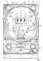
図1は、実施形態に係る遊技機1の正面図である。遊技機1は、遊技盤面2Aを構成する遊技盤(ゲージ盤)2と、遊技盤2を支持固定する遊技機用枠(台枠)3とから構成されている。遊技盤2には、ガイドレールによって囲まれた、ほぼ円形状の遊技領域2Bが形成されている。この遊技領域2Bには、遊技媒体としての遊技球が、所定の打球発射装置から発射されて打ち込まれる。なお、以下の説明において、「上下左右」は、遊技機1を正面から見たときの上下左右とする。
Hereinafter, a gaming machine according to an embodiment of the present invention will be described with reference to the drawings.
FIG. 1 is a front view of a gaming machine 1 according to the embodiment. The gaming machine 1 includes a gaming board (gauge board) 2 that constitutes the gaming board surface 2A, and a gaming machine frame (base frame) 3 that supports and fixes the gaming board 2. The game board 2 is formed with a substantially circular game area 2B surrounded by guide rails. In this game area 2B, a game ball as a game medium is launched from a predetermined hitting ball launching device and driven. In the following description, “up / down / left / right” refers to up / down / left / right when the gaming machine 1 is viewed from the front.

遊技盤面2Aの右側上下方向略中央の領域には、第1特別図柄表示装置4Aと、第2特別図柄表示装置4Bとが設けられている。第1特別図柄表示装置4Aと第2特別図柄表示装置4Bは、それぞれ、例えば7セグメントやドットマトリクスのLED(発光ダイオード)等から構成され、可変表示ゲームの一例となる特図ゲームにおいて、各々が識別可能な複数種類の識別情報(特別識別情報)である特別図柄(「特図」ともいう)を、変動可能に表示(可変表示)する。   A first special symbol display device 4A and a second special symbol display device 4B are provided in a region at the approximate center of the game board surface 2A on the right side in the vertical direction. The first special symbol display device 4A and the second special symbol display device 4B are each composed of, for example, 7-segment or dot matrix LEDs (light emitting diodes), etc. Special symbols (also referred to as “special graphics”), which are a plurality of types of identification information (special identification information) that can be identified, are displayed variably (variably displayed).

遊技盤面2Aの略中央の領域には、画像表示装置5が設けられている。画像表示装置5は、例えばLCD(液晶表示装置)等から構成され、各種の演出画像を表示する表示領域を形成している。画像表示装置5の表示領域では、特図ゲームにおける第1特別図柄表示装置4Aによる第1特図の可変表示や第2特別図柄表示装置4Bによる第2特図の可変表示のそれぞれに対応して、例えば3つといった複数に分割された可変表示部となる飾り図柄表示エリアにて、各々が識別可能な複数種類の識別情報(装飾識別情報)である飾り図柄を可変表示する。   An image display device 5 is provided in a substantially central region of the game board surface 2A. The image display device 5 is composed of, for example, an LCD (liquid crystal display device) or the like, and forms a display area for displaying various effect images. In the display area of the image display device 5, the first special symbol variable display by the first special symbol display device 4A and the second special symbol variable display by the second special symbol display device 4B in the special symbol game respectively correspond to the variable display. For example, in a decorative symbol display area serving as a variable display section divided into a plurality of parts such as three, decorative symbols which are a plurality of types of identification information (decorative identification information) each identifiable are variably displayed.

一例として、画像表示装置5の表示領域には、「左」、「中」、「右」の飾り図柄表示エリア5L、5C、5Rが配置されている。そして、特図ゲームにおいて第1特別図柄表示装置4Aによる第1特図の変動と第2特別図柄表示装置4Bによる第2特図の変動のいずれかが開始されることに対応して、「左」、「中」、「右」の各飾り図柄表示エリア5L、5C、5Rにて飾り図柄の変動(例えば上下方向のスクロール表示)が開始される。
その後、特図ゲームにおける可変表示結果として確定特別図柄が停止表示されるときに、画像表示装置5における「左」、「中」、「右」の各飾り図柄表示エリア5L、5C、5Rにて、飾り図柄の可変表示結果となる確定飾り図柄(最終停止図柄)が停止表示される。
As an example, “left”, “middle”, and “right” decorative symbol display areas 5L, 5C, and 5R are arranged in the display area of the image display device 5. In response to the start of either the first special symbol change by the first special symbol display device 4A or the second special symbol change by the second special symbol display device 4B in the special game, ”,“ Middle ”, and“ right ”decorative symbol display areas 5L, 5C, and 5R, the variation of decorative symbols (for example, vertical scroll display) is started.
Thereafter, when the fixed special symbol is stopped and displayed as a variable display result in the special symbol game, the “left”, “middle”, and “right” decorative symbol display areas 5L, 5C, and 5R in the image display device 5 are displayed. Then, the finalized decorative symbol (final stop symbol) that is the variable display result of the decorative symbol is stopped and displayed.

このように、画像表示装置5の表示領域では、第1特別図柄表示装置4Aによる第1特図を用いた特図ゲーム、又は、第2特別図柄表示装置4Bによる第2特図を用いた特図ゲームと同期して、各々が識別可能な複数種類の飾り図柄の可変表示を行い、可変表示結果となる確定飾り図柄を導出表示する。なお、表示結果を導出表示するとは、飾り図柄等の識別情報を停止表示(完全停止表示や最終停止表示ともいう)して可変表示を終了させることである。
そして、第1特別図柄表示装置4Aによる第1特図を用いた特図ゲーム、又は、第2特別図柄表示装置4Bによる第2特図を用いた特図ゲームにおいて、特定の特別図柄(大当り図柄)が停止表示されたときには、画像表示装置5における確定飾り図柄も大当たりとなる組み合わせで表示され、遊技者は、画像表示装置5の表示結果を視認して、「大当たり遊技状態」となることを判別することが可能となっている。
As described above, in the display area of the image display device 5, the special game using the first special symbol by the first special symbol display device 4A or the special special game using the second special symbol by the second special symbol display device 4B. In synchronization with the figure game, a variable display of a plurality of types of decorative patterns that can be identified is performed, and a fixed decorative pattern that is a variable display result is derived and displayed. Deriving and displaying the display result means that identification information such as a decorative symbol is stopped and displayed (also referred to as a complete stop display or a final stop display) and the variable display is ended.
Then, in a special game using the first special graphic by the first special symbol display device 4A or a special graphic game using the second special graphic by the second special symbol display device 4B, a specific special symbol (big hit symbol) ) Is displayed in a stopped state, the determined decorative symbols on the image display device 5 are also displayed in a combination that makes a big hit, and the player visually recognizes the display result on the image display device 5 and enters the “hit game state”. It is possible to discriminate.

第1特別図柄表示装置4Aによる特図ゲームは、画像表示装置5の下方に位置する振分装置50に形成された第1始動入賞口55aに進入した遊技球が、図示しない第1始動口スイッチによって検出されたことなどにより、基本的に開始される。また、第2特別図柄表示装置4Bによる特図ゲームは、振分装置50に形成された第2始動入賞口55bに進入した遊技球が図示しない第2始動口スイッチによって検出されたことなどにより、基本的に開始される。本実施形態では、第1始動入賞口55aおよび第2始動入賞口55bを通過した遊技球を、各々所定個数(例えば、各々4個ずつ、合計8個)の保留玉として記憶することが可能となっている。   In the special game by the first special symbol display device 4A, the game ball that has entered the first start winning port 55a formed in the sorting device 50 located below the image display device 5 is switched to a first start port switch (not shown). This is basically started by the fact that it has been detected. In addition, the special symbol game by the second special symbol display device 4B is based on the fact that the game ball that has entered the second start winning port 55b formed in the distribution device 50 is detected by a second start port switch (not shown). Basically started. In the present embodiment, it is possible to store the game balls that have passed through the first start winning opening 55a and the second starting winning opening 55b as a predetermined number (for example, four each, a total of eight). It has become.

画像表示装置5の表示領域下方には、始動入賞記憶表示エリア5Hが設けられており、記憶した保留玉の数(特図保留記憶数)を表示する。なお、始動入賞記憶表示エリア5Hとともに、あるいは始動入賞記憶表示エリア5Hに代えて、特図保留記憶数を表示する表示器を設けるようにしてもよい。図1に示す例では、始動入賞記憶表示エリア5Hとともに、第1特別図柄表示装置4A及び第2特別図柄表示装置4Bの上部に、特図保留記憶数を特定可能に表示するための第1保留表示器25Aと第2保留表示器25Bとが設けられている。第1保留表示器25Aは、第1始動入賞口55aに進入した有効始動入賞球数としての第1保留記憶数を特定可能に表示する。第2保留表示器25Bは、第2始動入賞口55bに進入した有効始動入賞球数としての第2保留記憶数を特定可能に表示する。第1保留表示器25Aと第2保留表示器25Bはそれぞれ、例えば第1保留記憶数と第2保留記憶数のそれぞれにおける上限値(例えば「4」)に対応した個数(例えば4個)のLEDを含んで構成されている。   Below the display area of the image display device 5, a start winning memory display area 5H is provided, which displays the number of stored balls (the number of special figure stored). In addition, you may make it provide the indicator which displays the number of special figure reservation memories with the start winning memory | storage display area 5H or it replaces with the starting winning memory display area 5H. In the example shown in FIG. 1, together with the start winning memory display area 5H, the first hold for displaying the special figure hold memory number in an identifiable manner on the upper part of the first special symbol display device 4A and the second special symbol display device 4B. A display 25A and a second hold display 25B are provided. The first hold indicator 25A displays the first hold memory number as the effective start winning ball number that has entered the first start winning opening 55a so as to be specified. The second hold indicator 25B displays the second hold memory number as the effective start winning ball number that has entered the second start winning opening 55b so that it can be specified. Each of the first hold indicator 25A and the second hold indicator 25B has, for example, a number (for example, four) of LEDs corresponding to an upper limit value (for example, “4”) in each of the first reserved memory number and the second reserved memory number. It is comprised including.

第1特別図柄表示装置4Aや第2特別図柄表示装置4Bによる特図ゲームでは、特別図柄の可変表示を開始させた後、特図変動時間となる所定時間が経過すると、特別図柄の可変表示結果となる確定特別図柄(特図表示結果)を導出表示する。このとき、確定特別図柄として特定の特別図柄(大当り図柄)が停止表示されれば、特定表示結果としての「大当り」となり、大当り図柄以外の特別図柄が停止表示されれば「ハズレ」となる。このような第1特別図柄表示装置4Aや第2特別図柄表示装置4Bによる特図ゲームの停止表示に応じて、画像表示装置5に確定飾り図柄も特定の組み合わせで表示される。
そして、特図ゲームでの可変表示結果が「大当り」になった後には、遊技者にとって有利なラウンド遊技(単に「ラウンド」ともいう)を所定回数実行する特定遊技状態としての上記「大当り遊技状態」に制御される。
In the special symbol game by the first special symbol display device 4A or the second special symbol display device 4B, after the special symbol variable display is started, the special symbol variable display result is obtained when a predetermined time as the special symbol variable time elapses. A definite special symbol (a special graph display result) is derived and displayed. At this time, if a specific special symbol (big hit symbol) is stopped and displayed as a confirmed special symbol, “big hit” is obtained as a specific display result, and if a special symbol other than the big hit symbol is stopped and displayed, “lost” is displayed. In response to the stop display of the special symbol game by the first special symbol display device 4A or the second special symbol display device 4B, the fixed decorative symbols are also displayed on the image display device 5 in a specific combination.
Then, after the variable display result in the special figure game becomes “big hit”, the “big hit gaming state” as a specific gaming state in which a round game advantageous to the player (also simply referred to as “round”) is executed a predetermined number of times. To be controlled.

振分装置50の下方には、特別可変入賞球装置7が設けられている。特別可変入賞球装置7は、図示しない大入賞口扉用となる図示しないソレノイドによって開閉駆動される大入賞口扉を備え、その大入賞口扉によって開放状態と閉鎖状態とに変化する大入賞口を形成する。一例として、特別可変入賞球装置7では、大入賞口扉用の上記ソレノイドがオフ状態であるときに大入賞口扉が大入賞口を閉鎖状態にする。その一方で、特別可変入賞球装置7では、大入賞口扉用のソレノイドがオン状態であるときに大入賞口扉が大入賞口を開放状態にする。特別可変入賞球装置7に形成された大入賞口に進入した遊技球は、図示しないカウントスイッチによって検出され、カウントスイッチによって遊技球が検出されたことに基づき、所定個数(例えば15個)の遊技球が賞球として払い出される。   A special variable winning ball device 7 is provided below the distribution device 50. The special variable winning ball apparatus 7 includes a large winning opening door that is opened and closed by a solenoid (not shown) for a large winning opening door (not shown), and changes into an open state and a closed state by the big winning opening door. Form. As an example, in the special variable winning ball apparatus 7, when the solenoid for the big prize opening door is in the off state, the big prize opening door closes the big prize opening. On the other hand, in the special variable winning ball apparatus 7, when the solenoid for the big prize opening door is in the ON state, the big prize opening door opens the big winning opening. A game ball that has entered a special winning opening formed in the special variable winning ball device 7 is detected by a count switch (not shown), and a predetermined number (for example, 15) of games is detected based on the detection of the game ball by the count switch. The ball is paid out as a prize ball.

特図ゲームにおける確定特別図柄として大当り図柄が停止表示された後に制御される特定遊技状態としての上記「大当り遊技状態」では、特別可変入賞球装置7の開閉板が、第1期間となる所定期間(例えば29秒間)あるいは所定個数(例えば9個)の入賞球が発生するまでの期間にて大入賞口を開放状態とすることにより、特別可変入賞球装置7を遊技者にとって有利な第1状態に変化させるラウンド遊技が実行される。こうしてラウンド遊技の実行中に大入賞口を開放状態とした開閉板は、遊技盤面2Aを落下する遊技球を受け止め、その後に大入賞口を閉鎖状態とすることにより、特別可変入賞球装置7を遊技者にとって不利な第2状態に変化させて、1回のラウンド遊技を終了させる。この実施の形態では、大入賞口の開放サイクルであるラウンド遊技の実行回数が、第1ラウンド数(例えば「6」)となる。ラウンド遊技の実行回数が「15」となる大当り遊技状態における遊技は、15回開放遊技とも称される。このような大当り遊技状態では、大入賞口に遊技球が入賞するたびに15個の出玉が得られる。   In the “big hit game state” as the specific game state controlled after the big hit symbol is stopped and displayed as a confirmed special symbol in the special figure game, the open / close plate of the special variable winning ball apparatus 7 is a predetermined period which is the first period. A first variable state in which the special variable winning ball device 7 is advantageous to the player by opening the large winning opening in a period until the predetermined number (for example, nine) of winning balls (for example, 29 seconds) or a predetermined number (for example, nine) is generated. A round game to be changed to is executed. In this way, the open / close plate that opened the grand prize opening during the execution of the round game receives the game ball falling on the game board surface 2A, and then closed the special prize opening, thereby allowing the special variable prize ball device 7 to be opened. It changes to the 2nd state unfavorable for a player, and complete | finishes one round game. In this embodiment, the number of executions of the round game, which is the opening cycle of the special winning opening, is the first round number (for example, “6”). A game in the big hit game state in which the number of executions of the round game is “15” is also referred to as a 15-time open game. In such a big hit gaming state, 15 balls are obtained each time a game ball wins a big winning opening.

遊技盤面2Aにおける画像表示装置5の上部左方、上部右方、下部左方および下部右方には、それぞれ遊技球の流下方向や速度を変化させる風車10A,10B,10C,10Dが設けられている。また、遊技盤面2Aには、同様に遊技球の流下方向や速度を変化させる不図示の複数の障害釘、誘導釘群等が設けられている。また、遊技盤面2Aの最下方には、いずれの入賞口にも進入しなかった遊技球が取り込まれるアウト口11が設けられている。さらに、遊技機用枠3の左右上部位置には、効果音等を再生出力するためのスピーカ8L,8Rが設けられ、遊技領域2B周辺部には、遊技効果ランプ9が設けられている。   Wind turbines 10A, 10B, 10C, and 10D that change the flow direction and speed of the game balls are provided on the upper left, upper right, lower left, and lower right of the image display device 5 on the game board surface 2A, respectively. Yes. Similarly, the game board surface 2A is provided with a plurality of unillustrated obstacle nails, a guide nail group, and the like that change the flow direction and speed of the game balls. Further, at the lowermost part of the game board surface 2A, there is provided an out port 11 through which game balls that have not entered any winning port are taken. Furthermore, speakers 8L and 8R for reproducing and outputting sound effects and the like are provided at the upper left and right positions of the gaming machine frame 3, and a game effect lamp 9 is provided in the periphery of the game area 2B.

また、遊技盤面2Aにおける画像表示装置5の上方には、画像表示装置5の上縁部に沿って左右に延在する上側フランジ部材12が設けられ、画像表示装置5の下方には、画像表示装置5の下縁部に沿って左右に延在する下側フランジ部材13が設けられている。上側フランジ部材12および下側フランジ部材13は、遊技盤面2Aからやや前方(遊技盤面2Aに直交する方向)に張り出して設けられ、着色等を施されており、遊技機の装飾部材として機能する。   Further, an upper flange member 12 extending left and right along the upper edge of the image display device 5 is provided above the image display device 5 on the game board surface 2A, and an image display is provided below the image display device 5. A lower flange member 13 extending left and right along the lower edge of the device 5 is provided. The upper flange member 12 and the lower flange member 13 are provided so as to protrude slightly forward (in a direction orthogonal to the game board surface 2A) from the game board surface 2A, are colored, and function as decorative members for the gaming machine.

遊技機用枠3の右下部位置には、遊技媒体としての遊技球を遊技領域に向けて発射するために遊技者等によって操作される打球操作ハンドル30(操作ノブ)が設けられている。また、遊技領域の下方における遊技機用枠3の所定位置には、賞球として払い出された遊技球や所定の球貸機により貸し出された遊技球を、打球発射装置へと供給可能に保持(貯留)する上皿等が設けられる。   At the lower right position of the gaming machine frame 3, a hitting operation handle 30 (operation knob) operated by a player or the like for launching a game ball as a game medium toward the game area is provided. In addition, at a predetermined position of the gaming machine frame 3 below the game area, a game ball paid out as a prize ball or a game ball lent out by a predetermined ball lending machine is held so as to be supplied to the ball hitting device. An upper plate or the like for storage is provided.

本実施形態の遊技機1は、画像表示装置5の中央下方に、第1始動入賞口55aおよび第2始動入賞口55bが形成された振分装置50と、遊技球が流入可能な流入口58(第1流入口58aおよび第2流入口58b)とを備えている。以下に、振分装置50および流入口58について詳細に説明する。   The gaming machine 1 according to the present embodiment includes a distribution device 50 in which a first start winning port 55a and a second starting winning port 55b are formed below the center of the image display device 5, and an inflow port 58 through which game balls can flow. (First inflow port 58a and second inflow port 58b). Below, the distribution apparatus 50 and the inflow port 58 are demonstrated in detail.

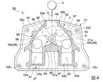
図2は、振分装置50の斜視図であり、図3は、図2におけるフロントカバー部材60の正面壁61を除去したときの振分装置50の斜視図であり、図4は図3のA矢視図である。
図2に示すように、振分装置50は、ベース部材51と、ベース部材51の正面側に配置されたフロントカバー部材60と、ベース部材51の背面側に配置されたバックカバー部材70とにより構成されている。
2 is a perspective view of the sorting apparatus 50, FIG. 3 is a perspective view of the sorting apparatus 50 when the front wall 61 of the front cover member 60 in FIG. 2 is removed, and FIG. 4 is a perspective view of FIG. FIG.
As shown in FIG. 2, the sorting device 50 includes a base member 51, a front cover member 60 disposed on the front side of the base member 51, and a back cover member 70 disposed on the back side of the base member 51. It is configured.

図3に示すように、ベース部材51は、上方に短辺を有し、下方に長辺を有する正面視で略台形状をした板部材である。図4に示すように、ベース部材51の四隅には、ベース部材51の厚さ方向に貫通する貫通孔52a〜52dが形成されている。振分装置50は、例えばベース部材51の各貫通孔52a〜52dに、不図示の螺子等を挿通して遊技盤面2A(図1参照)に締結することで、遊技領域2B(図1参照)内に固定支持される。   As shown in FIG. 3, the base member 51 is a plate member having a substantially trapezoidal shape in a front view having a short side on the upper side and a long side on the lower side. As shown in FIG. 4, through holes 52 a to 52 d that penetrate in the thickness direction of the base member 51 are formed at the four corners of the base member 51. For example, the distribution device 50 is inserted into the through holes 52a to 52d of the base member 51 with screws (not shown) or the like and fastened to the game board surface 2A (see FIG. 1), thereby playing the game area 2B (see FIG. 1). Fixed and supported inside.

図2に示すように、フロントカバー部材60は、例えばポリカーボネート樹脂やアクリル樹脂等の光透過性を有する樹脂材料により形成されている。フロントカバー部材60は、ベース部材51の前面51aの所定領域を囲繞する周壁63と、周壁63の正面側に設けられる正面壁61と、により形成されている。   As shown in FIG. 2, the front cover member 60 is formed of a light-transmitting resin material such as polycarbonate resin or acrylic resin. The front cover member 60 is formed by a peripheral wall 63 that surrounds a predetermined region of the front surface 51 a of the base member 51, and a front wall 61 that is provided on the front side of the peripheral wall 63.

図4に示すように、周壁63は、遊技盤2(図1参照)の前後方向に所定の高さを有し、ベース部材51の左右中間部を挟んで左右両側に対称に配置される一対の側壁部65,66(左側壁部65および右側壁部66)と、一対の側壁部65,66の下端部65a,66aを接続する下壁部67と、により形成されている。
一対の側壁部65,66は、それぞれ上端部65b,66bが離間して配置されている。一対の側壁部65,66は、ベース部材51の上下中間部よりも上方においては、上方から下方に向かって互いの離間距離が漸次広くなるように形成され、ベース部材51の上下中間部よりも下方においては、上下方向に沿うように、かつ互いの離間距離が略一定となるように形成されている。
下壁部67は、一対の側壁部65,66の下端部65a,66aから、それぞれ内側に向かって水平に延びるとともに、左右中間部が上方に向かって凸をなす仕切り部67aとなっている。
図2に示すように、正面壁61は、周壁63の正面側に設けられており、周壁63により囲繞されたベース部材51の前面51aの所定領域を正面側から閉塞している。
As shown in FIG. 4, the peripheral wall 63 has a predetermined height in the front-rear direction of the game board 2 (see FIG. 1), and is a pair that is symmetrically disposed on both the left and right sides with the left and right intermediate part of the base member 51 interposed therebetween. Side wall portions 65, 66 (the left side wall portion 65 and the right side wall portion 66) and a lower wall portion 67 connecting the lower end portions 65a, 66a of the pair of side wall portions 65, 66.
The pair of side wall portions 65 and 66 are arranged such that upper end portions 65b and 66b are separated from each other. The pair of side wall portions 65, 66 are formed so that the distance from each other gradually increases from the upper side to the lower side above the upper and lower middle portions of the base member 51, and is higher than the upper and lower middle portions of the base member 51. In the lower part, it is formed along the vertical direction so that the distance between them is substantially constant.
The lower wall portion 67 is a partition portion 67a that extends horizontally inwardly from the lower end portions 65a and 66a of the pair of side wall portions 65 and 66, and the left and right intermediate portions project upward.
As shown in FIG. 2, the front wall 61 is provided on the front side of the peripheral wall 63, and closes a predetermined region of the front surface 51 a of the base member 51 surrounded by the peripheral wall 63 from the front side.

上述のように形成されたフロントカバー部材60は、例えば不図示の裸子等により周壁63がベース部材51に固定されて、ベース部材51の前面51aに配置される。これにより、図4に示すように、ベース部材51の正面側には、ベース部材51と、フロントカバー部材60の側壁部65,66および正面壁61(図2参照)とにより、遊技球Pを誘導する誘導領域80が画成される。また、図3に示すように、誘導領域80の上方には、ベース部材51と、フロントカバー部材60の側壁部65,66の上端部65b,66bおよび正面壁61(図2参照)とにより、誘導領域80の内外を連通し、遊技球P(図4参照)が進入可能な進入口68が形成される。   The front cover member 60 formed as described above is disposed on the front surface 51 a of the base member 51 with the peripheral wall 63 fixed to the base member 51 by, for example, a naked child (not shown). Accordingly, as shown in FIG. 4, the game ball P is placed on the front side of the base member 51 by the base member 51, the side wall portions 65 and 66 of the front cover member 60, and the front wall 61 (see FIG. 2). A guiding area 80 to be guided is defined. Further, as shown in FIG. 3, above the guiding region 80, the base member 51, upper end portions 65 b and 66 b of the side wall portions 65 and 66 of the front cover member 60, and the front wall 61 (see FIG. 2), An entrance 68 that allows the game ball P (see FIG. 4) to enter is formed through communication between the inside and outside of the guidance area 80.

図4に示すように、遊技球Pの誘導領域80には、仕切り部67aによって、仕切り部67aの左側に第1領域81が画成され、仕切り部67aの右側に第2領域82が画成されている。
本実施形態においては、第1領域81として第1始動入賞口55aが形成されており、第2領域82として第2始動入賞口55bが形成されている。第1始動入賞口55aおよび第2始動入賞口55bは、それぞれベース部材51を貫通して形成されており、遊技球Pがベース部材51の正面側から背面側に向かって通過可能となっている。第1始動入賞口55aおよび第2始動入賞口55bの開口縁部には、それぞれ図示しない第1始動口スイッチおよび第2始動口スイッチが設けられており、それぞれ遊技球Pが第1始動入賞口55aおよび第2始動入賞口55bに進入したことを検知する。
As shown in FIG. 4, a first area 81 is defined on the left side of the partition part 67a and a second area 82 is defined on the right side of the partition part 67a by the partition part 67a. Has been.
In the present embodiment, a first start winning port 55 a is formed as the first region 81, and a second start winning port 55 b is formed as the second region 82. The first start winning port 55a and the second start winning port 55b are respectively formed through the base member 51 so that the game ball P can pass from the front side to the back side of the base member 51. . A first start port switch and a second start port switch (not shown) are provided at the opening edge portions of the first start winning port 55a and the second start winning port 55b, respectively. 55a and the second start winning opening 55b are detected.

また、遊技球Pの誘導領域80には、仕切り部67aの上方であって、振分装置50の左右中間部よりも左側に、第1領域81である第1始動入賞口55aと連通する第1誘導路86が形成され、振分装置50の左右中間部よりも右側に、第2領域82である第2始動入賞口55bと連通する第2誘導路87が形成されている。以下、第1誘導路86と第2誘導路87との境界を境界S(図4において一点鎖線により図示)とする。   In addition, the guidance area 80 of the game ball P is connected to the first start winning port 55a which is the first area 81 above the partition portion 67a and on the left side of the left and right middle portion of the sorting device 50. A first guide path 86 is formed, and a second guide path 87 that communicates with the second start winning port 55 b that is the second region 82 is formed on the right side of the left and right intermediate portion of the distribution device 50. Hereinafter, a boundary between the first guiding path 86 and the second guiding path 87 is defined as a boundary S (illustrated by a one-dot chain line in FIG. 4).

また、遊技球Pの誘導領域80には、仕切り部67aの上方であって、第1誘導路86と第2誘導路87との境界S上に、遊技盤面2A(図1参照)と直交する方向に沿う軸部材99に回動自在に軸支され、回動することにより第1誘導路86および第2誘導路のいずれかに遊技球Pを振り分ける回動振分部材90を備えている。なお、本実施形態の軸部材99は、例えばベース部材51から遊技盤面2A(図1参照)と直交する方向に沿って立設されており、ベース部材51と一体形成されている。   Further, the guidance area 80 of the game ball P is above the partition portion 67a and on the boundary S between the first guidance path 86 and the second guidance path 87, and is orthogonal to the game board surface 2A (see FIG. 1). A pivotal distribution member 90 is provided that is pivotally supported by a shaft member 99 along the direction and distributes the game balls P to either the first guiding path 86 or the second guiding path by rotating. Note that the shaft member 99 of the present embodiment is erected along the direction orthogonal to the game board surface 2A (see FIG. 1), for example, from the base member 51, and is integrally formed with the base member 51.

図5は、回動振分部材90の正面図である。なお、図5では、軸部材99と回動振分部材90との隙間を誇張して表現している。また、軸部材99と回動振分部材90とは、共通軸線に対して同軸上に配置される。以下、この共通軸線を中心軸Oという。
図5に示すように、回動振分部材90は、軸部材99に挿通されて中心軸O回りに回動自在に軸支される筒状部91と、筒状部91の外周面92から筒状部91の径方向に沿って外側に張り出す切替羽根部95(手段9の「切替部」に相当。)と、中心軸Oを挟んで切替羽根部95とは反対側において、筒状部91の外周面92から切替羽根部95と直交する方向に沿って外側に張り出す一対の規制羽根部96,97(左側規制羽根部96および右側規制羽根部97)と、により形成されている。筒状部91、切替羽根部95および一対の規制羽根部96,97は、互いに一体形成されている。
FIG. 5 is a front view of the rotation distribution member 90. In FIG. 5, the gap between the shaft member 99 and the rotation distribution member 90 is exaggerated. Moreover, the shaft member 99 and the rotation distribution member 90 are disposed coaxially with respect to the common axis. Hereinafter, this common axis is referred to as a central axis O.
As shown in FIG. 5, the rotation distributing member 90 is inserted into the shaft member 99 and supported from the cylindrical portion 91 that is pivotally supported around the central axis O, and the outer peripheral surface 92 of the cylindrical portion 91. A switching blade portion 95 (corresponding to a “switching portion” of the means 9) projecting outward along the radial direction of the tubular portion 91 and a tubular shape on the opposite side of the switching blade portion 95 across the central axis O. A pair of restricting blade portions 96 and 97 (a left restricting blade portion 96 and a right restricting blade portion 97) projecting outward from the outer peripheral surface 92 of the portion 91 along a direction orthogonal to the switching blade portion 95. . The cylindrical portion 91, the switching blade portion 95, and the pair of regulating blade portions 96 and 97 are integrally formed with each other.

図4に示すように、回動振分部材90は、切替羽根部95が上方に配置され、一対の規制羽根部96,97が下方に配置された状態で軸部材99に軸支される。
回動振分部材90は、中心軸O回りに回動することで、第1誘導路86および第2誘導路87のいずれかに切り替え可能となっている。具体的には、回動振分部材90の切替羽根部95は、回動振分部材90が時計回りに回動した状態において、第2誘導路87側に傾斜配置されて第2誘導路87への遊技球Pの流入を規制するとともに第1誘導路86へ遊技球Pを導く。
As shown in FIG. 4, the rotation distribution member 90 is pivotally supported by the shaft member 99 with the switching blade portion 95 disposed above and the pair of regulating blade portions 96 and 97 disposed below.
The rotation distribution member 90 can be switched to either the first guide path 86 or the second guide path 87 by rotating about the central axis O. Specifically, the switching blade portion 95 of the rotation distribution member 90 is inclined and arranged on the second guide path 87 side in a state where the rotation distribution member 90 rotates clockwise. The game ball P is guided to the first guide path 86 while restricting the inflow of the game ball P to the first guide path 86.

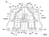
図6は、回動振分部材90が図4に示す状態から反時計回りに回動したときの説明図である。
また、図6に示すように、回動振分部材90の切替羽根部95は、回動振分部材90が反時計回りに回動した状態において、第1誘導路86側に傾斜配置されて第1誘導路86への遊技球Pの流入を規制するとともに、第2誘導路87へ遊技球Pを導く。このように、遊技球Pは、回動振分部材90の切替羽根部95の位置に応じて、第1誘導路86および第2誘導路87のいずれかに振り分けられることになる。
FIG. 6 is an explanatory view when the rotation distribution member 90 is rotated counterclockwise from the state shown in FIG.
Further, as shown in FIG. 6, the switching blade portion 95 of the rotation distribution member 90 is inclined and arranged on the first guide path 86 side in a state where the rotation distribution member 90 is rotated counterclockwise. While restricting the inflow of the game ball P to the first guide path 86, the game ball P is guided to the second guide path 87. In this way, the game balls P are distributed to either the first guide path 86 or the second guide path 87 according to the position of the switching blade portion 95 of the rotation distribution member 90.

回動振分部材90の回動角度は、一対の規制羽根部96,97がそれぞれ仕切り部67aの上端に当接することにより、例えば30°程度に規制される。なお、図4においては、回動振分部材90が時計回りに回動し、切替羽根部95が第2誘導路87側に傾斜配置されるとともに、右側規制羽根部97が仕切り部67aの上端に当接して回動振分部材90の回動が規制されている状態を図示している。また、図6においては、回動振分部材90が反時計回りに回動し、切替羽根部95が第1誘導路86側に傾斜配置されるとともに、左側規制羽根部96が仕切り部67aの上端に当接して回動振分部材90の回動が規制されている状態を図示している。   The rotation angle of the rotation distribution member 90 is regulated to about 30 °, for example, by the pair of regulating blade portions 96 and 97 coming into contact with the upper end of the partition portion 67a. In FIG. 4, the rotation distributing member 90 rotates clockwise, the switching blade portion 95 is inclined to the second guide path 87 side, and the right regulating blade portion 97 is the upper end of the partition portion 67a. A state is shown in which the rotation of the rotation distribution member 90 is restricted in contact with the rotation. Further, in FIG. 6, the rotation distribution member 90 rotates counterclockwise, the switching blade portion 95 is inclined on the first guide path 86 side, and the left regulating blade portion 96 is disposed on the partition portion 67a. The state which contact | abutted at the upper end and the rotation of the rotation distribution member 90 is controlled is shown in figure.

図5に示すように、軸部材99の外周面のうち上方における境界Sに対応する位置には、上方に向かって凸となる第1突起部99a(手段9の「保持規制手段」に相当。)が設けられている。また、回動振分部材90の内周面93のうち、筒状部91を挟んで切替羽根部95とは反対側の位置には、軸部材99に向かって凸となる第2突起部93a(手段9の「保持規制手段」に相当。)が設けられている。第1突起部99aおよび第2突起部93aは、それぞれ先端が所定の曲率を有する曲面形状に形成されている。   As shown in FIG. 5, a position corresponding to the upper boundary S on the outer peripheral surface of the shaft member 99 corresponds to a first protrusion 99 a that protrudes upward (corresponding to “holding restricting means” of the means 9). ) Is provided. Further, a second projecting portion 93 a that protrudes toward the shaft member 99 at a position on the opposite side of the switching blade portion 95 across the tubular portion 91 of the inner peripheral surface 93 of the rotation distributing member 90. (Corresponding to "holding restricting means" of means 9) is provided. The first protrusion 99a and the second protrusion 93a are each formed in a curved surface shape having a predetermined curvature at the tip.

軸部材99の第1突起部99aと切替羽根部95の第2突起部93aとは、切替羽根部95が境界Sに沿うように位置したとき、互いの先端が当接する。このとき、第1突起部99aおよび第2突起部93aの互いの先端は、それぞれ曲面形状であることから、回動振分部材90の自重によって、第2突起部93aが第1突起部99aの先端の曲面形状に沿って第1突起部99aの左方または右方に移動し、さらに、軸部材99の外周面に沿って移動する。これにより、回動振分部材90が時計回り又は反時計回りに回動するため、切替羽根部95は、境界Sに沿う位置に保持されるのが規制されて、常に第1誘導路86(図4参照)側および第2誘導路87(図4参照)側のいずれかに配置される。したがって、図4に示すように、進入口68から進入した遊技球Pは、切替羽根部95によって必ず第1誘導路86または第2誘導路87のいずれかに交互に誘導されるので(図4では、第1誘導路86に誘導される場合を図示)、遊技球Pが切替羽根部95によって第1誘導路86および第2誘導路87のいずれにも誘導されずに進入口68を塞ぐ、いわゆる玉詰まりを防止できる。   When the switching blade portion 95 is positioned along the boundary S, the first protrusion 99a of the shaft member 99 and the second protrusion 93a of the switching blade portion 95 are in contact with each other. At this time, since the tip ends of the first protrusion 99a and the second protrusion 93a are each curved, the second protrusion 93a is connected to the first protrusion 99a by its own weight. It moves to the left or right of the first protrusion 99 a along the curved surface shape of the tip, and further moves along the outer peripheral surface of the shaft member 99. Thereby, since the rotation distribution member 90 rotates clockwise or counterclockwise, the switching blade portion 95 is restricted from being held at the position along the boundary S, and is always the first guide path 86 ( 4) and the second guiding path 87 (see FIG. 4). Therefore, as shown in FIG. 4, the game ball P that has entered from the entrance 68 is always guided alternately to either the first guide path 86 or the second guide path 87 by the switching blade portion 95 (FIG. 4). Then, the case where the game ball P is guided to the first guide path 86 is illustrated), and the game ball P is not guided to either the first guide path 86 or the second guide path 87 by the switching blade portion 95, and closes the entrance 68. So-called clogging can be prevented.

振分装置50には、第1誘導路86および第2誘導路87の背面側の位置に、遊技球Pが流入する流入口58が設けられている。本実施形態の振分装置50では、第1誘導路86の背面側の位置に第1流入口58aが設けられ、第2誘導路87の背面側の位置に第2流入口58bが設けられている。
第1流入口58aは、第1誘導路86の背面側の位置であって、第1始動入賞口55aの上方の位置において、ベース部材51を貫通して形成されており、遊技球Pがベース部材51の正面側から背面側に向かって通過可能となっている。第2流入口58bは、第2誘導路87の背面側の位置であって、第2始動入賞口55bの上方の位置において、第1流入口58aと同様にベース部材51を貫通して形成されており、遊技球Pがベース部材51の正面側から背面側に向かって通過可能となっている。
The sorting apparatus 50 is provided with an inlet 58 through which the game ball P flows at positions on the back side of the first guide path 86 and the second guide path 87. In the distribution device 50 of the present embodiment, a first inflow port 58 a is provided at a position on the back side of the first guide path 86, and a second inflow port 58 b is provided at a position on the back side of the second guide path 87. Yes.
The first inflow port 58a is formed at the position on the back side of the first guide path 86 and above the first start winning prize opening 55a so as to pass through the base member 51, and the game ball P is the base. The member 51 can pass from the front side toward the back side. The second inflow port 58b is formed at the position on the back side of the second guide path 87 and through the base member 51 in the same position as the first inflow port 58a at a position above the second start winning prize port 55b. The game ball P can pass from the front side of the base member 51 toward the back side.

本実施形態においては、第1流入口58aおよび第2流入口58bに流入した遊技球Pは、遊技機1(図1参照)の外部に排出されるようになっており、第1流入口58aおよび第2流入口58bは、いわゆるアウト口となっている。
また、第1流入口58aおよび第2流入口58bは、それぞれ円形状に形成され、第1流入口58aの直径および第2流入口58bの直径は、それぞれ互いに略同一となっている。さらに、第1流入口58aの直径および第2流入口58bの直径は、それぞれ遊技球Pの直径よりもわずかに大径になるように形成されている。したがって、遊技球Pは、第1流入口58aおよび第2流入口58bに一度に複数個流入することができなくなり、一球ずつ流入することになる。なお、例えば遊技球Pの直径が11mmであった場合、第1流入口58aの直径および第2流入口58bの直径は、11mmよりも大きく21mm以下程度の範囲に設定されてもよい。また、第1流入口58aの直径および第2流入口58bの形状は、円形状に限定されるものではなく、例えば矩形状等であってもよい。
In the present embodiment, the game ball P flowing into the first inflow port 58a and the second inflow port 58b is discharged to the outside of the gaming machine 1 (see FIG. 1), and the first inflow port 58a. And the 2nd inflow port 58b is what is called an out port.
The first inlet 58a and the second inlet 58b are each formed in a circular shape, and the diameter of the first inlet 58a and the diameter of the second inlet 58b are substantially the same. Further, the diameter of the first inflow port 58a and the diameter of the second inflow port 58b are each formed to be slightly larger than the diameter of the game ball P. Accordingly, a plurality of game balls P cannot flow into the first inflow port 58a and the second inflow port 58b at a time, and flow in one ball at a time. For example, when the diameter of the game ball P is 11 mm, the diameter of the first inflow port 58a and the diameter of the second inflow port 58b may be set in a range from about 11 mm to about 21 mm. Further, the diameter of the first inflow port 58a and the shape of the second inflow port 58b are not limited to a circular shape, and may be, for example, a rectangular shape.

図2に示すように、バックカバー部材70は、例えばポリカーボネート樹脂やアクリル樹脂等の光透過性を有する樹脂材料により形成されている。バックカバー部材70は、中空の部材であり、ベース部材51の背面側に配置されて、ベース部材51の後面51bを覆うように形成されるとともに、内部が第1流入口58a、第2流入口58b、第1始動入賞口55aおよび第2始動入賞口55b(いずれも図4参照)と連通している。第1流入口58a、第2流入口58b、第1始動入賞口55aおよび第2始動入賞口55bに流入した遊技球P(図4参照)は、バックカバー部材70を介して遊技機1(図1参照)の外部に排出される。   As shown in FIG. 2, the back cover member 70 is formed of a light-transmissive resin material such as polycarbonate resin or acrylic resin. The back cover member 70 is a hollow member, is disposed on the back side of the base member 51 and is formed so as to cover the rear surface 51b of the base member 51, and the inside thereof includes a first inlet 58a and a second inlet. 58b, the first start winning port 55a and the second start winning port 55b (both see FIG. 4). The game ball P (see FIG. 4) that has flowed into the first inflow port 58a, the second inflow port 58b, the first start winning port 55a, and the second starting winning port 55b is connected to the gaming machine 1 (see FIG. 4) via the back cover member 70. 1)).

続いて、上記の振分装置50を備えた遊技機1の遊技内容の概略について説明する。
図1に示すように、まず打球操作ハンドル30が操作されて発射された遊技球P(図4参照)が遊技盤面2Aに達すると、遊技球Pは釘等に当たりながら下方に自然落下する。図4に示すように、遊技球Pは、落下する過程で振分装置50の進入口68から振分装置50の内部の誘導領域80に進入すると、回動振分部材90によって、誘導領域80内に形成された第1誘導路86および第2誘導路87のいずれかの誘導路に振り分けられる。例えば、図4のように、回動振分部材90の切替羽根部95が第2誘導路87側に傾斜配置されて第2誘導路87への遊技球Pの流入が規制されている状態において、遊技球Pが誘導領域80に進入した場合を説明する。このとき、遊技球Pは、傾斜した切替羽根部95に衝突した後、切替羽根部95の左側面に沿うように、第1誘導路86に向かって移動する。
その後、図6に示すように、遊技球Pは、左側規制羽根部96の上面に衝突するとともに、遊技球Pの自重により左側規制羽根部96を下方に押圧する。これにより、回動振分部材90は、反時計回りに回動するとともに、遊技球Pを第1誘導路86に誘導する。
Next, an outline of game contents of the gaming machine 1 including the above-described distribution device 50 will be described.
As shown in FIG. 1, first, when a game ball P (see FIG. 4) launched by operating a hitting operation handle 30 reaches the game board surface 2A, the game ball P naturally falls downward while hitting a nail or the like. As shown in FIG. 4, when the game ball P enters the guiding area 80 inside the sorting apparatus 50 from the entrance 68 of the sorting apparatus 50 in the process of falling, the guiding area 80 is moved by the rotating sorting member 90. The first guide path 86 and the second guide path 87 formed inside are distributed to one of the guide paths. For example, as shown in FIG. 4, in the state where the switching blade portion 95 of the rotational distribution member 90 is inclined to the second guide path 87 side and the inflow of the game ball P to the second guide path 87 is restricted. A case where the game ball P enters the guidance area 80 will be described. At this time, the game ball P moves toward the first guide path 86 along the left side surface of the switching blade portion 95 after colliding with the inclined switching blade portion 95.
After that, as shown in FIG. 6, the game ball P collides with the upper surface of the left regulating blade portion 96 and presses the left regulating blade portion 96 downward by its own weight. Thereby, the rotation distribution member 90 rotates counterclockwise and guides the game ball P to the first guide path 86.

ここで、本実施形態の振分装置50にあっては、第1誘導路86の背面側に第1流入口58aが設けられている。したがって、第1誘導路86に誘導された遊技球Pは、第1流入口58aに流入するか、もしくは第1流入口58a下方の第1始動入賞口55a(すなわち第1領域81)に導かれる。遊技球Pが第1流入口58aに流入した場合には、遊技球Pは、バックカバー部材70(図2参照)を介して遊技機1(図1参照)の外部に排出される。   Here, in the sorting device 50 of the present embodiment, the first inflow port 58 a is provided on the back side of the first guide path 86. Accordingly, the game ball P guided to the first guide path 86 flows into the first inflow port 58a or is guided to the first start winning port 55a (that is, the first region 81) below the first inflow port 58a. . When the game ball P flows into the first inflow port 58a, the game ball P is discharged outside the game machine 1 (see FIG. 1) via the back cover member 70 (see FIG. 2).

これに対して、遊技球Pが第1流入口58aの下方に形成された第1始動入賞口55aに流入した場合には、第1始動入賞口55aに設けられた図示しない第1始動口スイッチは、遊技球Pが第1始動入賞口55aに進入したことを検知する。そして、図1に示すように、この検出信号に基づいて、第1特別図柄表示装置4Aによる特図ゲームが開始され、所定時間後に、特別図柄の可変表示結果となる確定特別図柄(特図表示結果)が導出表示される。   On the other hand, when the game ball P flows into the first start winning port 55a formed below the first inflow port 58a, a first start port switch (not shown) provided in the first start winning port 55a. Detects that the game ball P has entered the first start winning opening 55a. Then, as shown in FIG. 1, based on this detection signal, a special symbol game is started by the first special symbol display device 4A, and after a predetermined time, a fixed special symbol (special symbol display) that becomes a variable symbol display result. Result) is displayed.

また、図6に示すように、回動振分部材90が反時計回りに回動した後、進入口68から次の遊技球(不図示)が進入した場合には、遊技球は、傾斜した切替羽根部95に衝突した後、切替羽根部95の右側面に沿うように、第2誘導路87に向かって移動する。その後、遊技球は、右側規制羽根部97の上面に衝突するとともに、遊技球の自重により右側規制羽根部97を下方に押圧する。これにより、回動振分部材90は、時計回りに回動するとともに、遊技球を第2誘導路87に誘導する。   In addition, as shown in FIG. 6, when the next game ball (not shown) enters from the entrance 68 after the rotation distribution member 90 rotates counterclockwise, the game ball is inclined. After colliding with the switching blade portion 95, it moves toward the second guide path 87 along the right side surface of the switching blade portion 95. Thereafter, the game ball collides with the upper surface of the right regulating blade portion 97 and presses the right regulating blade portion 97 downward by its own weight. Thereby, the rotation distribution member 90 rotates clockwise and guides the game ball to the second guide path 87.

そして、第2誘導路87に誘導された遊技球は、第2流入口58bに流入するか、もしくは第2流入口58b下方の第2始動入賞口55b(すなわち第2領域82)に導かれる。遊技球が第2流入口58bに流入した場合には、遊技球は、バックカバー部材70を介して遊技機1(図1参照)の外部に排出される。これに対して、遊技球が第2始動入賞口55bに流入した場合には、図1に示すように、図示しない第2始動口スイッチの検出信号に基づいて、第2特別図柄表示装置4Bによる特図ゲームが開始され、所定時間後に、特別図柄の可変表示結果となる確定特別図柄(特図表示結果)が導出表示される。
以降、進入口68から遊技球が進入するごとに、遊技球は、振分装置50によって第1誘導路86と第2誘導路87とに交互に振り分けられ、上述の動作が繰り返される。
Then, the game ball guided to the second guide path 87 flows into the second inflow port 58b or is guided to the second start winning port 55b (that is, the second region 82) below the second inflow port 58b. When the game ball flows into the second inflow port 58b, the game ball is discharged to the outside of the gaming machine 1 (see FIG. 1) via the back cover member 70. On the other hand, when the game ball flows into the second start winning opening 55b, as shown in FIG. 1, the second special symbol display device 4B uses a detection signal from a second start opening switch (not shown). A special symbol game is started, and after a predetermined time, a definite special symbol (special symbol display result) that is a variable symbol variable display result is derived and displayed.
Thereafter, each time a game ball enters from the entrance 68, the game ball is alternately distributed to the first guide path 86 and the second guide path 87 by the distribution device 50, and the above-described operation is repeated.

画像表示装置5の表示領域では、第1特別図柄表示装置4Aによる第1特図を用いた特図ゲーム、又は、第2特別図柄表示装置4Bによる第2特図を用いた特図ゲームと同期して、各々が識別可能な複数種類の飾り図柄の可変表示を行い、可変表示結果となる確定飾り図柄を導出表示する。
そして、第1特別図柄表示装置4Aによる第1特図を用いた特図ゲーム、又は、第2特別図柄表示装置4Bによる第2特図を用いた特図ゲームにおいて、特定の特別図柄(大当り図柄)が停止表示されたときには、画像表示装置5における確定飾り図柄も大当たりとなる組み合わせで表示され、「大当り遊技状態」に制御される。
In the display area of the image display device 5, a special game using the first special symbol by the first special symbol display device 4A or a special game using the second special symbol by the second special symbol display device 4B is synchronized. Then, a plurality of types of decorative symbols that can be identified are variably displayed, and a definite decorative symbol that is a variable display result is derived and displayed.
Then, in a special game using the first special graphic by the first special symbol display device 4A or a special graphic game using the second special graphic by the second special symbol display device 4B, a specific special symbol (big hit symbol) ) Is displayed in a stopped state, the confirmed decorative symbols on the image display device 5 are also displayed in a combination that makes a big hit, and are controlled to the “big hit gaming state”.

本実施形態の遊技機1によれば、振分装置50の第1誘導路86および第2誘導路87の背面側の位置に、遊技球が流入する第1流入口58aおよび第2流入口58bがそれぞれ設けられているので、遊技球は、進入口68から振分装置50内に進入した後、第1誘導路86および第2誘導路87のいずれかを通過中に、遊技球が第1流入口58aおよび第2流入口58bに流入するか、もしくは第1領域81である第1始動入賞口55aおよび第2領域82である第2始動入賞口55bのいずれかに導かれる。このため、遊技球が進入口68から振分装置50内に進入し、第1誘導路86および第2誘導路87のいずれかに振り分けられた後であっても、遊技球の動きに遊技者の注目を集めることができるので、遊技の興趣を向上できる。   According to the gaming machine 1 of the present embodiment, the first inflow port 58a and the second inflow port 58b into which game balls flow into the positions on the back side of the first guide path 86 and the second guide path 87 of the sorting device 50. Since the game balls enter the sorting device 50 from the entrance 68 and pass through either the first guide path 86 or the second guide path 87, the game balls are in the first direction. It flows into the inflow port 58a and the second inflow port 58b, or is guided to either the first start winning port 55a that is the first region 81 or the second starting winning port 55b that is the second region 82. For this reason, even after the game ball enters the sorting device 50 from the entrance 68 and is distributed to either the first guide path 86 or the second guide path 87, the player is not affected by the movement of the game ball. Because it can attract attention, it can improve the interest of the game.

また、振分装置50の第1誘導路86および第2誘導路87の背面側の位置に遊技球が流入する第1流入口58aおよび第2流入口58bを設けているので、例えば、第1流入口58aおよび第2流入口58bをフロントカバー部材60の周壁63等に設けた場合よりも、フロントカバー部材60の強度を確保できる。しかも、本実施形態においては、フロントカバー部材60の周壁63が第1誘導路86、第2誘導路87、第1領域81および第2領域82を囲むように連続形成されている。これにより、フロントカバー部材60の強度を格段に向上できる。さらに、強度確保に起因するフロントカバー部材60の大型化を防止できるので、振分装置50をコンパクトに形成でき、遊技機1の設計自由度を向上させることができる。   Moreover, since the 1st inflow port 58a and the 2nd inflow port 58b into which a game ball | bowl flows in are provided in the position of the back side of the 1st guide path 86 and the 2nd guide path 87 of the distribution apparatus 50, for example, it is 1st The strength of the front cover member 60 can be secured as compared with the case where the inflow port 58a and the second inflow port 58b are provided on the peripheral wall 63 of the front cover member 60 or the like. Moreover, in the present embodiment, the peripheral wall 63 of the front cover member 60 is continuously formed so as to surround the first guide path 86, the second guide path 87, the first region 81, and the second region 82. Thereby, the strength of the front cover member 60 can be significantly improved. Furthermore, since the enlargement of the front cover member 60 due to securing the strength can be prevented, the sorting device 50 can be formed in a compact manner, and the degree of design freedom of the gaming machine 1 can be improved.

また、第1流入口58aおよび第2流入口58bに流入した遊技球Pは、遊技機1(図1参照)の外部に排出されるようになっており、第1流入口58aおよび第2流入口58bは、いわゆるアウト口となっているので、遊技球Pが振分装置50に進入した後であっても、遊技者に対して、遊技球Pが遊技機1の外部に排出されるという危機感を与えることができるので、遊技球Pの動きに遊技者の注目を集めることができる。   In addition, the game ball P that has flowed into the first inlet 58a and the second inlet 58b is discharged to the outside of the gaming machine 1 (see FIG. 1), and the first inlet 58a and the second inlet Since the entrance 58b is a so-called outlet, the game ball P is discharged to the outside of the gaming machine 1 to the player even after the game ball P has entered the sorting device 50. Since a sense of crisis can be given, the player's attention can be drawn to the movement of the game ball P.

また、第1流入口58aおよび第2流入口58bは、それぞれ円形状に形成され、第1流入口58aの直径および第2流入口58bの直径は、それぞれ互いに略同一であるので、第1誘導路86および第2誘導路87のいずれの誘導路に振り分けられたかに関わらず、同じ確率で遊技球Pが第1流入口58aおよび第2流入口58bに流入する可能性がある。したがって、第1誘導路86および第2誘導路87のいずれの誘導路に振り分けられたかに影響されることなく、遊技球Pの動きに遊技者の注目を最後まで集めることができる。   Further, the first inlet 58a and the second inlet 58b are each formed in a circular shape, and the diameter of the first inlet 58a and the diameter of the second inlet 58b are substantially the same as each other. Regardless of which of the guide path 86 and the second guide path 87 is assigned, the game ball P may flow into the first inflow port 58a and the second inflow port 58b with the same probability. Therefore, the player's attention can be gathered to the end of the movement of the game ball P without being influenced by which one of the first guide path 86 and the second guide path 87 is assigned.

また、第1流入口58aの直径および第2流入口58bの直径は、それぞれ遊技球Pの直径よりもわずかに大径になるように形成されているので、遊技球Pは、第1流入口58aおよび第2流入口58bに一度に複数個流入することができなくなり、一球ずつ流入することになる。したがって、遊技球Pが第1流入口58aおよび第2流入口58bに過剰に流入するのを抑制できる。   Further, since the diameter of the first inflow port 58a and the diameter of the second inflow port 58b are each formed to be slightly larger than the diameter of the game ball P, the game ball P is It becomes impossible for a plurality to flow into 58a and the 2nd inflow port 58b at a time, and it flows in one ball at a time. Therefore, it is possible to prevent the game ball P from excessively flowing into the first inflow port 58a and the second inflow port 58b.

(実施形態の変形例)
図7は、実施形態の変形例に係る遊技機1の正面図である。
続いて、実施形態の変形例に係る遊技機1について説明する。
実施形態に係る遊技機1は、振分装置50の第1流入口58aおよび第2流入口58bに流入した遊技球が遊技機1(図1参照)の外部に排出されていた。
これに対して、実施形態の変形例に係る遊技機1は、図7に示すように、振分装置50の第1流入口58aおよび第2流入口58bに流入した遊技球が迂回路15を介して遊技領域2Bに排出される点で、実施形態とは異なっている。なお、実施形態と同様の構成部分については詳細な説明を省略し、異なる部分についてのみ説明する。
(Modification of the embodiment)
FIG. 7 is a front view of the gaming machine 1 according to a modification of the embodiment.
Subsequently, a gaming machine 1 according to a modification of the embodiment will be described.
In the gaming machine 1 according to the embodiment, the game balls that have flowed into the first inflow port 58a and the second inflow port 58b of the sorting device 50 are discharged to the outside of the gaming machine 1 (see FIG. 1).
In contrast, in the gaming machine 1 according to the modified example of the embodiment, as shown in FIG. 7, the game balls that flow into the first inlet 58 a and the second inlet 58 b of the sorting device 50 pass through the detour 15. This is different from the embodiment in that it is discharged to the game area 2B. Detailed description of the same components as those in the embodiment will be omitted, and only different portions will be described.

図7に示すように、迂回路15は、例えばポリカーボネート樹脂やアクリル樹脂等の光透過性を有する樹脂材料等により長尺のパイプ状に形成されている。迂回路15の一方端部は、例えば図4に示すバックカバー部材70を介して、振分装置50の第1流入口58aおよび第2流入口58bと連結されている。
また、図7に示すように、迂回路15の他方端部は、遊技盤面2Aに形成された迂回路排出孔17と連結されている。これにより、振分装置50の第1流入口58aおよび第2流入口58b(図4参照)に流入した遊技球は、迂回路15を通流して迂回路排出孔17から遊技領域2Bに排出される。
迂回路排出孔17の下方には、小入賞口18が設けられている。小入賞口18には、迂回路排出孔17から排出された遊技球が進入可能となっている。小入賞口18に遊技球が進入すると、図示しないカウントスイッチによって遊技球の進入が検出され、所定個数(例えば7個)の遊技球が賞球として払い出される。
実施形態の変形例によれば、遊技球が第1流入口58aおよび第2流入口58b(図4参照)に流入した後も、遊技球の動きに遊技者の注目を集めることができる。
As shown in FIG. 7, the bypass 15 is formed in a long pipe shape from a resin material having optical transparency such as polycarbonate resin and acrylic resin. One end of the detour 15 is connected to the first inlet 58a and the second inlet 58b of the sorting device 50, for example, via a back cover member 70 shown in FIG.
As shown in FIG. 7, the other end of the bypass 15 is connected to a bypass discharge hole 17 formed in the game board surface 2A. Thereby, the game balls that have flowed into the first inflow port 58a and the second inflow port 58b (see FIG. 4) of the distribution device 50 flow through the detour 15 and are discharged from the detour discharge hole 17 to the game area 2B. The
A small winning opening 18 is provided below the detour discharge hole 17. A game ball discharged from the bypass discharge hole 17 can enter the small prize winning opening 18. When a game ball enters the small prize opening 18, the entry of the game ball is detected by a count switch (not shown), and a predetermined number (for example, seven) of game balls are paid out as a prize ball.
According to the modification of the embodiment, even after the game ball flows into the first inflow port 58a and the second inflow port 58b (see FIG. 4), it is possible to attract the player's attention to the movement of the game ball.

なお、この発明の技術範囲は上記の実施形態に限られるものではなく、本発明の趣旨を逸脱しない範囲において種々の変更を加えることが可能である。   The technical scope of the present invention is not limited to the above embodiment, and various modifications can be made without departing from the spirit of the present invention.

実施形態および実施形態の変形例では、第1誘導路86の背面側の位置に第1流入口58aが設けられ、第2誘導路87の背面側の位置に第2流入口58bが設けられていた。これに対して、例えば、第1誘導路86および第2誘導路87の背面側の位置において、第1誘導路86および第2誘導路87に跨るように、流入口を形成してもよい。この場合、第1誘導路86および第2誘導路87のいずれの誘導路に振り分けられたかに関わらず、遊技球が流入口に流入した後、同一の流路で遊技球を導くことができる。
また、流入口の形状は、円形状に限られることはなく、例えば長円形状であってもよい。さらに、流入口が長円形状に形成されたときの流入口の幅は、遊技球の直径と略同一か、若干広く形成されていてもよい。これにより、遊技球は、流入口に一度に複数個流入するのが抑制されるので、遊技球が流入口に過剰に流入するのを抑制できる。
In the embodiment and the modification of the embodiment, the first inflow port 58 a is provided at the position on the back side of the first guide path 86, and the second inflow port 58 b is provided at the position on the back side of the second guide path 87. It was. On the other hand, for example, the inlet may be formed so as to straddle the first guide path 86 and the second guide path 87 at positions on the back side of the first guide path 86 and the second guide path 87. In this case, the game ball can be guided through the same flow path after the game ball has flowed into the inflow port regardless of which of the first guide path 86 and the second guide path 87 is distributed.
Further, the shape of the inflow port is not limited to a circular shape, and may be, for example, an oval shape. Further, the width of the inflow port when the inflow port is formed in an oval shape may be substantially the same as or slightly wider than the diameter of the game ball. Thereby, since a plurality of game balls are prevented from flowing into the inflow port at a time, it is possible to suppress an excessive flow of game balls into the inflow port.

実施形態および実施形態の変形例では、第1流入口58aの直径および第2流入口58bの直径は、それぞれ互いに同一であった。これに対して、第1流入口58aの直径および第2流入口58bの直径は、それぞれ互いに異なっていてもよい。これにより、第1誘導路86および第2誘導路87のいずれの誘導路に振り分けられたかに関わらず、遊技球が第1流入口58aおよび第2流入口58bに流入する可能性を保持しつつ、第1誘導路86および第2誘導路87のいずれの誘導路に振り分けられたかによって、遊技球が流入口(第1流入口58aおよび第2流入口58b)に流入する確率を異ならせることができる。したがって、遊技球の動きに遊技者の注目を最後まで集めることができる。   In the embodiment and the modification of the embodiment, the diameter of the first inflow port 58a and the diameter of the second inflow port 58b are respectively the same. On the other hand, the diameter of the first inlet 58a and the diameter of the second inlet 58b may be different from each other. Thereby, regardless of which of the first guide path 86 and the second guide path 87 is assigned, the possibility that the game ball flows into the first inflow port 58a and the second inflow port 58b is maintained. Depending on which one of the first guide path 86 and the second guide path 87 is assigned, the probability that the game ball flows into the inflow port (the first inflow port 58a and the second inflow port 58b) may be varied. it can. Therefore, the player's attention can be gathered to the end of the movement of the game ball.

遊技機1の形態は、実施形態および実施形態の変形例に限定されることはない。例えば、実施形態と実施形態の変形例とを組み合わせてもよい。この場合、例えば第1流入口58aに遊技球が流入した場合には、遊技球は遊技機1の外部に排出され、第2流入口58bに遊技球が流入した場合には、遊技球は迂回路を通流して遊技機1の遊技領域2Bに排出される構成としてもよい。   The form of the gaming machine 1 is not limited to the embodiment and the modified example of the embodiment. For example, you may combine embodiment and the modification of embodiment. In this case, for example, when the game ball flows into the first inflow port 58a, the game ball is discharged to the outside of the gaming machine 1, and when the game ball flows into the second inflow port 58b, the game ball is bypassed. It is good also as a structure which flows through the path | route and is discharged to the game area 2B of the gaming machine 1.

実施形態および実施形態の変形例では、第1領域81として第1始動入賞口55aが形成され、第2領域82として第2始動入賞口55bが形成されていたが、第1始動入賞口55aおよび第2始動入賞口55bに限定されることはなく、例えば、大入賞口や小入賞口等であってもよい。   In the embodiment and the modified example of the embodiment, the first start winning opening 55a is formed as the first area 81 and the second starting winning opening 55b is formed as the second area 82, but the first start winning opening 55a and It is not limited to the 2nd start winning opening 55b, For example, a big winning opening, a small winning opening, etc. may be sufficient.

実施形態および実施形態の変形例では、切替羽根部95が第1誘導路86と第2誘導路87との境界Sに沿う位置に保持されるのを規制するための保持規制手段として、軸部材99に第1突起部99aを設け、回動振分部材90に第2突起部93aを設けていたが、保持規制手段はこれに限定されない。例えば、仕切り部67aを磁性材料で形成するとともに、一対の規制羽根部96,97の各先端部に保持規制手段としてマグネットを設け、このマグネットを保持規制手段としてもよい。具体的には、一対の規制羽根部96,97のうち一方の規制羽根部と、仕切り部67aの上端とを磁力により吸着させ、振分装置50に進入した遊技球が他方の規制羽根部の上面に衝突したときに、一方の規制羽根部が仕切り部67aの上端から離反するとともに、他方の規制羽根部が仕切り部67aの上端に吸着されるように構成してもよい。この場合においても、切替羽根部95が第1誘導路86と第2誘導路87との境界Sに沿う位置に保持されるのを規制できる。   In the embodiment and the modification of the embodiment, the shaft member is used as a holding restricting means for restricting the switching blade portion 95 from being held at a position along the boundary S between the first guide path 86 and the second guide path 87. Although the first protrusion 99a is provided in 99 and the second protrusion 93a is provided in the rotation distribution member 90, the holding restricting means is not limited to this. For example, the partition portion 67a may be formed of a magnetic material, and a magnet may be provided as a holding restricting means at each tip of the pair of restricting blade portions 96 and 97, and this magnet may be used as the holding restricting means. Specifically, one of the pair of regulating blade portions 96 and 97 and the upper end of the partition portion 67a are adsorbed by a magnetic force, and the game ball that has entered the distribution device 50 is attached to the other regulating blade portion. When the upper surface collides, one restriction blade part may be separated from the upper end of the partition part 67a, and the other restriction blade part may be attracted to the upper end of the partition part 67a. Even in this case, the switching blade portion 95 can be restricted from being held at a position along the boundary S between the first guide path 86 and the second guide path 87.

その他、本発明の趣旨を逸脱しない範囲で、上記した実施の形態における構成要素を周知の構成要素に置き換えることは適宜可能であり、また、上記した変形例を適宜組み合わせてもよい。   In addition, it is possible to appropriately replace the constituent elements in the above-described embodiments with well-known constituent elements without departing from the spirit of the present invention, and the above-described modified examples may be appropriately combined.

1 遊技機
2A 遊技盤面
2B 遊技領域
50 振分装置
58 流入口
58a 第1流入口
58b 第2流入口
68 進入口
81 第1領域
82 第2領域
86 第1誘導路
87 第2誘導路
P 遊技球
DESCRIPTION OF SYMBOLS 1 Game machine 2A Game board surface 2B Game area | region 50 Distribution apparatus 58 Inflow port 58a 1st inflow port 58b 2nd inflow port 68 Advancement entrance 81 1st area | region 82 2nd area | region 86 1st induction path 87 2nd induction path P Game ball

Claims (1)

遊技盤面の遊技領域に遊技球を発射することにより遊技が行われる遊技機であって、
進入口から進入した前記遊技球を第1領域と第2領域とに誘導する第1誘導路および第2誘導路を形成する振分装置と、
前記遊技領域に設けられる開口から構成され、前記遊技球が流入する流入口と、
を備え、
前記流入口は、前記振分装置における前記第1誘導路および前記第2誘導路の背面側の位置に設けられていることを特徴とする遊技機。
A gaming machine in which a game is performed by firing a game ball on a game area of a game board surface,
A sorting device that forms a first guiding path and a second guiding path for guiding the game ball entered from the entrance to the first area and the second area;
An opening formed in the gaming area, into which the gaming ball flows;
With
The game machine according to claim 1, wherein the inflow port is provided at a position on a back side of the first guiding path and the second guiding path in the sorting device.
JP2012261009A 2012-11-29 2012-11-29 Game machine Pending JP2014104256A (en)

Priority Applications (1)

Application Number Priority Date Filing Date Title
JP2012261009A JP2014104256A (en) 2012-11-29 2012-11-29 Game machine

Applications Claiming Priority (1)

Application Number Priority Date Filing Date Title
JP2012261009A JP2014104256A (en) 2012-11-29 2012-11-29 Game machine

Publications (1)

Publication Number Publication Date
JP2014104256A true JP2014104256A (en) 2014-06-09

Family

ID=51026235

Family Applications (1)

Application Number Title Priority Date Filing Date
JP2012261009A Pending JP2014104256A (en) 2012-11-29 2012-11-29 Game machine

Country Status (1)

Country Link
JP (1) JP2014104256A (en)

Citations (2)

* Cited by examiner, † Cited by third party
Publication number Priority date Publication date Assignee Title
JPH08191931A (en) * 1995-01-19 1996-07-30 Heiwa Corp Pachinko machine
JPH1142332A (en) * 1997-07-28 1999-02-16 Daiichi Shokai Co Ltd Prize winning device for pachinko machine

Patent Citations (2)

* Cited by examiner, † Cited by third party
Publication number Priority date Publication date Assignee Title
JPH08191931A (en) * 1995-01-19 1996-07-30 Heiwa Corp Pachinko machine
JPH1142332A (en) * 1997-07-28 1999-02-16 Daiichi Shokai Co Ltd Prize winning device for pachinko machine

Similar Documents

Publication Publication Date Title
JP6782988B2 (en) Game machine
JP6534967B2 (en) Gaming machine
JP6607702B2 (en) Game machine
JP5415595B2 (en) Game machine
JP6312998B2 (en) Game machine
JP6534966B2 (en) Gaming machine
JP6215122B2 (en) Game machine
JP2017006521A (en) Game machine
JP7377557B2 (en) gaming machine
JP2014104256A (en) Game machine
JP2015198746A (en) Game machine
JP2023015935A (en) game machine
JP2017086574A (en) Pinball game machine
JP6121360B2 (en) Game machine
JP6031013B2 (en) Game machine
JP5802913B2 (en) Game machine
JP6549539B2 (en) Gaming machine
JP5544473B2 (en) Game machine
JP6782987B2 (en) Game machine
JP6616384B2 (en) Game machine
JP2023015936A (en) game machine
JP6286328B2 (en) Game machine
JP2005185368A (en) Pinball game machine
JP2023015937A (en) game machine
JP6286327B2 (en) Game machine

Legal Events

Date Code Title Description
A621 Written request for application examination

Free format text: JAPANESE INTERMEDIATE CODE: A621

Effective date: 20151009

A131 Notification of reasons for refusal

Free format text: JAPANESE INTERMEDIATE CODE: A131

Effective date: 20160823

A977 Report on retrieval

Free format text: JAPANESE INTERMEDIATE CODE: A971007

Effective date: 20160824

A521 Request for written amendment filed

Free format text: JAPANESE INTERMEDIATE CODE: A523

Effective date: 20161019

A02 Decision of refusal

Free format text: JAPANESE INTERMEDIATE CODE: A02

Effective date: 20170321