JP2014103655A - Method for controlling portable device by using humidity sensor and portable device thereof - Google Patents
Method for controlling portable device by using humidity sensor and portable device thereof Download PDFInfo
- Publication number
- JP2014103655A JP2014103655A JP2013147995A JP2013147995A JP2014103655A JP 2014103655 A JP2014103655 A JP 2014103655A JP 2013147995 A JP2013147995 A JP 2013147995A JP 2013147995 A JP2013147995 A JP 2013147995A JP 2014103655 A JP2014103655 A JP 2014103655A
- Authority
- JP
- Japan
- Prior art keywords
- humidity
- portable device
- sensor
- display unit
- call
- Prior art date
- Legal status (The legal status is an assumption and is not a legal conclusion. Google has not performed a legal analysis and makes no representation as to the accuracy of the status listed.)
- Granted
Links
Images


Classifications
-
- H—ELECTRICITY
- H04—ELECTRIC COMMUNICATION TECHNIQUE
- H04B—TRANSMISSION
- H04B1/00—Details of transmission systems, not covered by a single one of groups H04B3/00 - H04B13/00; Details of transmission systems not characterised by the medium used for transmission
- H04B1/38—Transceivers, i.e. devices in which transmitter and receiver form a structural unit and in which at least one part is used for functions of transmitting and receiving
- H04B1/40—Circuits
-
- H—ELECTRICITY
- H04—ELECTRIC COMMUNICATION TECHNIQUE
- H04W—WIRELESS COMMUNICATION NETWORKS
- H04W8/00—Network data management
- H04W8/22—Processing or transfer of terminal data, e.g. status or physical capabilities
-
- H—ELECTRICITY
- H04—ELECTRIC COMMUNICATION TECHNIQUE
- H04M—TELEPHONIC COMMUNICATION
- H04M1/00—Substation equipment, e.g. for use by subscribers
- H04M1/02—Constructional features of telephone sets
- H04M1/0202—Portable telephone sets, e.g. cordless phones, mobile phones or bar type handsets
- H04M1/026—Details of the structure or mounting of specific components
-
- H—ELECTRICITY
- H04—ELECTRIC COMMUNICATION TECHNIQUE
- H04M—TELEPHONIC COMMUNICATION
- H04M1/00—Substation equipment, e.g. for use by subscribers
- H04M1/72—Mobile telephones; Cordless telephones, i.e. devices for establishing wireless links to base stations without route selection
- H04M1/724—User interfaces specially adapted for cordless or mobile telephones
- H04M1/72448—User interfaces specially adapted for cordless or mobile telephones with means for adapting the functionality of the device according to specific conditions
- H04M1/72454—User interfaces specially adapted for cordless or mobile telephones with means for adapting the functionality of the device according to specific conditions according to context-related or environment-related conditions
-
- H—ELECTRICITY
- H04—ELECTRIC COMMUNICATION TECHNIQUE
- H04M—TELEPHONIC COMMUNICATION
- H04M1/00—Substation equipment, e.g. for use by subscribers
- H04M1/72—Mobile telephones; Cordless telephones, i.e. devices for establishing wireless links to base stations without route selection
- H04M1/724—User interfaces specially adapted for cordless or mobile telephones
- H04M1/72448—User interfaces specially adapted for cordless or mobile telephones with means for adapting the functionality of the device according to specific conditions
- H04M1/72463—User interfaces specially adapted for cordless or mobile telephones with means for adapting the functionality of the device according to specific conditions to restrict the functionality of the device
- H04M1/724631—User interfaces specially adapted for cordless or mobile telephones with means for adapting the functionality of the device according to specific conditions to restrict the functionality of the device by limiting the access to the user interface, e.g. locking a touch-screen or a keypad
-
- H—ELECTRICITY
- H04—ELECTRIC COMMUNICATION TECHNIQUE
- H04M—TELEPHONIC COMMUNICATION
- H04M2250/00—Details of telephonic subscriber devices
- H04M2250/04—Details of telephonic subscriber devices including near field communication means, e.g. RFID
-
- H—ELECTRICITY
- H04—ELECTRIC COMMUNICATION TECHNIQUE
- H04M—TELEPHONIC COMMUNICATION
- H04M2250/00—Details of telephonic subscriber devices
- H04M2250/12—Details of telephonic subscriber devices including a sensor for measuring a physical value, e.g. temperature or motion
-
- Y—GENERAL TAGGING OF NEW TECHNOLOGICAL DEVELOPMENTS; GENERAL TAGGING OF CROSS-SECTIONAL TECHNOLOGIES SPANNING OVER SEVERAL SECTIONS OF THE IPC; TECHNICAL SUBJECTS COVERED BY FORMER USPC CROSS-REFERENCE ART COLLECTIONS [XRACs] AND DIGESTS
- Y02—TECHNOLOGIES OR APPLICATIONS FOR MITIGATION OR ADAPTATION AGAINST CLIMATE CHANGE
- Y02D—CLIMATE CHANGE MITIGATION TECHNOLOGIES IN INFORMATION AND COMMUNICATION TECHNOLOGIES [ICT], I.E. INFORMATION AND COMMUNICATION TECHNOLOGIES AIMING AT THE REDUCTION OF THEIR OWN ENERGY USE
- Y02D30/00—Reducing energy consumption in communication networks
- Y02D30/70—Reducing energy consumption in communication networks in wireless communication networks
Landscapes
- Engineering & Computer Science (AREA)
- Signal Processing (AREA)
- Computer Networks & Wireless Communication (AREA)
- Human Computer Interaction (AREA)
- Environmental & Geological Engineering (AREA)
- Databases & Information Systems (AREA)
- Telephone Function (AREA)
- Investigating Or Analyzing Materials By The Use Of Electric Means (AREA)
- Telephone Set Structure (AREA)
- Air Conditioning Control Device (AREA)
Abstract
Description
本発明は湿度センサーを用いた携帯装置制御方法及びその携帯装置に係り、より詳しくは特に湿度センサーを用いて通話中の表示部のオン/オフを制御する携帯装置制御方法及びその携帯装置に関する。 The present invention relates to a mobile device control method using a humidity sensor and the mobile device, and more particularly to a mobile device control method for controlling on / off of a display unit during a call using the humidity sensor and the mobile device.
スマートフォンを含めた今日の携帯装置は、写真及び/又は動画の撮影、 音楽ファイルや動画ファイルの再生、ゲーム、放送の受信、無線インターネット支援など複雑な機能を備えるようになり、これによって電力消費量も増加するようになった。このため、携帯装置内部で起きる不必要な動作を最小化することによって電力消費を減らすことが要求される。 Today's mobile devices, including smartphones, have complex functions such as taking pictures and / or videos, playing music and video files, playing games, broadcasting, and supporting the wireless Internet. Also began to increase. For this reason, it is required to reduce power consumption by minimizing unnecessary operations occurring inside the portable device.
電力消費を減らす一例としては、 使用者が表示部を見ていない場合、表示部を自動でオフする方法がある。現在、常用されている携帯装置の場合、既設定された時間の間、何らかの入力が発生しないか、近接センサーを用いて使用者の顔(特に耳部分)などが携帯装置に密着されている場合、表示部を自動でオフさせる。 One example of reducing power consumption is a method of automatically turning off the display unit when the user is not looking at the display unit. In the case of a portable device that is currently in common use, no input is generated for a preset time, or the user's face (especially the ear portion) is in close contact with the portable device using a proximity sensor The display unit is automatically turned off.
しかし、現在の表示部制御は近接センサーの人体認識範囲が狭いので、人体の近接を正確に認識できないとか、 センサーに異物がついて誤作動する場合が多いという問題点がある。また、一定時間の間、入力が発生しない時、表示部をオフさせる場合には、表示部がオンされている時間の間、電力が消費されるのでその效用は大きくない。 However, the current display control has a problem that the proximity sensor's human body recognition range is narrow, so that the proximity of the human body cannot be accurately recognized, or the sensor often malfunctions due to a foreign object. In addition, when the display unit is turned off when no input is generated for a certain period of time, power is consumed during the time the display unit is turned on, so the effect is not great.
本発明は湿度センサーを用いて湿度の変化を基に表示部のオン/オフを制御する携帯装置制御方法及びその携帯装置を提供する。 The present invention provides a portable device control method for controlling on / off of a display unit based on a change in humidity using a humidity sensor, and a portable device thereof.
また、本発明は、携帯装置のケースのホール(開口)をマイクロフォンと共有する湿度センサーを用いる携帯装置制御方法及びその携帯装置を提供する。 The present invention also provides a portable device control method using a humidity sensor that shares a hole (opening) of a portable device case with a microphone, and a portable device thereof.
上記課題を解決するための本発明による携帯装置の制御方法は、 湿度センサーを備える携帯装置の制御方法であって、通話イベントが発生すると、上記湿度センサーを用いて上記携帯装置周辺の湿度を測定する段階と、 上記測定された湿度を既設定された臨界値と比べる段階と、その比較結果によって上記携帯装置の表示部のオン/オフを制御する段階と、を含むことを特徴とする。 A method for controlling a portable device according to the present invention for solving the above-described problem is a method for controlling a portable device including a humidity sensor. When a call event occurs, the humidity around the portable device is measured using the humidity sensor. A step of comparing the measured humidity with a preset critical value, and a step of controlling on / off of the display unit of the portable device according to the comparison result.
また、上記課題を解決するための本発明による携帯装置は、携帯装置周辺の湿度を測定する湿度センサー、情報を表示する表示部、及び通話を行うための通話イベントが発生すると、 上記湿度センサーを用いて上記携帯装置周辺の湿度を測定するように上記湿度センサーを制御し、上記測定された湿度を既設定された臨界値と比べて、その比較結果によって上記表示部のオン/オフを制御する制御部を含むことを特徴とする。 In addition, a mobile device according to the present invention for solving the above-described problems includes a humidity sensor that measures humidity around the mobile device, a display unit that displays information, and a call event for performing a call. And controlling the humidity sensor to measure the humidity around the portable device, comparing the measured humidity with a preset critical value, and controlling on / off of the display unit according to the comparison result A control unit is included.
上記課題を解決するための本発明による携帯装置の制御方法によれば、通話イベントが発生すると、上記湿度センサーを用いて上記携帯装置周辺の湿度を測定する段階と、 上記測定された湿度を既設定された臨界値と比べる段階と、その比較結果によって上記携帯装置の表示部のオン/オフを制御する段階と、を含むことにより電力の消費を少なくできる。 According to a method for controlling a portable device according to the present invention for solving the above-described problem, when a call event occurs, the step of measuring the humidity around the portable device using the humidity sensor, and the measured humidity is already measured. Power consumption can be reduced by including the step of comparing with the set critical value and the step of controlling on / off of the display unit of the portable device according to the comparison result.
本発明は湿度センサーを備える携帯装置の制御に適用される。
また、本発明は湿度センサーを備える携帯装置として、スマートフォン(Smart Phone)、 携帯端末(Portable Terminal)、 移動端末(Mobile Terminal)、個人情報端末(Personal Digital Assistant:PDA)、PMP(Portable Multimedia Player)端末、 ノートパッド(Note Pad)、ワイブロ(Wibro)端末などの一般的な電子端末だけではなく、湿度センサーの具備が可能なすべての装置のために適用できる。
The present invention is applied to control of a portable device having a humidity sensor.
In addition, the present invention provides a mobile device including a humidity sensor as a smartphone (Smart Phone), a mobile terminal (Portable Terminal), a mobile terminal (Mobile Terminal), a personal information terminal (Personal Digital Assistant: PDA), and a PMP (Portable Multi Media). The present invention can be applied not only to a general electronic terminal such as a terminal, a note pad, and a Wibro terminal, but also to all devices that can include a humidity sensor.
本明細書で使用される技術的用語はただ特定の実施例を説明するために使用されたもので、本発明の思想を限定しようとする意図ではないことに留意すべきである。また、本明細書で使用される技術的用語は本明細書で特別に他の意味に定義されない限り、 本発明が属する分野で通常の知識を有する者によって一般的に理解される意味に解釈されるべきであり、過度に包括的な意味に解釈されたり過度に縮小された意味に解釈されてはいけない。 It should be noted that the technical terms used herein are merely used to describe particular embodiments and are not intended to limit the spirit of the present invention. In addition, technical terms used in this specification are construed as generally understood by a person having ordinary knowledge in the field to which the present invention belongs, unless specifically defined otherwise in this specification. Should not be interpreted in an overly comprehensive sense or in an overly reduced meaning.
また、本明細書で用いる単数の表現は文脈上明白に異なるように記載しない限り、複数の表現を含む。本明細書において、「構成される」又は「含む」などの用語は明細書上に記載された多くの構成要素、 或いは多くの段階を必ず全部含むことに解釈されてはいけない。 Moreover, the singular forms used herein include the plural unless the context clearly dictates otherwise. In this specification, terms such as “configured” or “including” should not be construed as necessarily including all of the many elements or many steps recited in the specification.
以下、添付の図面を参照して本発明の実施例をより具体的に説明する。
図1は本発明による携帯装置の構成を示したブロック図である。
図1を参照すれば、携帯装置100は通信部110、入力部120、音声入力部130、 センサー部140、制御部150、貯蔵部160及び表示部170を含んで構成される。
Hereinafter, embodiments of the present invention will be described in detail with reference to the accompanying drawings.
FIG. 1 is a block diagram showing a configuration of a portable device according to the present invention.
Referring to FIG. 1, the
通信部110は移動通信網内で基地局、外部の携帯装置、サーバーの中の少なくとも1つと無線信号を送受信する。ここで、無線信号は音声コール信号、画像通話コール信号又は文字/マルチメディアメッセージ送受信による多様な形態のデータを含む。
The
入力部120は使用者の入力を感知し、使用者入力に対応する入力信号を制御部150に伝達する。入力部120はキーパッド、ドームスィッチ、タッチパッド(静圧/静電)、ジョグホイール、ジョグスイッチ、フィンガーマウス、ホイールなどを含んで構成される。
The
入力部120は入力パッドから構成される。入力部120は後述するセンサー部140の各種センサーを実装する形態から構成されることができる。例えば、入力部120は入力パッド上にタッチセンサー141がフィルム形態で付着したり、 パネル形態で結合された入力パッドから構成されることができる。或いは入力部120は電磁気センサー142を用いるEMR(Electro Magnetic Resonance)又はEMI(Eletro Magnetic Interferenc)方式の入力パッドから構成されることができる。
The
入力部120は後述する表示部170とレイヤー構造を成して入力スクリーンとして動作することができる。例えば、 入力部120はタッチセンサー141を備える入力パッドを含み、表示部170と結合されたTSP(Touch Screen Panel)から構成されることができる。表示部170とレイヤー構造を成す入力部120はタッチスクリーンを構成する。
The
本発明の実施例によれば、 入力部120は通話遂行のための使用者の入力を感知する。
According to the embodiment of the present invention, the
音声入力部130はオーディオ信号入力のためのものでマイクなどを含む。マイクは通話モード、録音モードまたは音声認識モードなどで外部の音響信号を入力し電気的な音声データに処理する。通話モードで処理された音声データは通信部110を通じて基地局に送信される。
The
センサー部140は携帯装置100の現在状態を感知するための複数センサーから構成される。センサー部140は感知された状態に対応する制御信号を生成し、制御部150に伝達する。センサー部140はタッチセンサー141、電磁気センサー142及び近接センサー143及び湿度センサー144を含む。
The
タッチセンサー141は使用者のタッチ入力を感知する。タッチセンサー141は例えば、タッチフィルム、 タッチシート、タッチパッドなどの形態を有する。タッチセンサー141はタッチ入力を感知し、 感知されたタッチ信号を制御部150に伝達する。制御部150はタッチ信号を分析してタッチ信号に対応する動作を行う。また、感知されたタッチ信号に対応する情報が表示部170上に表示されることができる。タッチセンサー141は多様な入力手段に基づく使用者のタッチ入力による操作信号を受信する。タッチセンサー141は使用者の人体(例えば、手)や物理的な道具、スタイラスペン(Stylus Pen)及びスタイラスペンに含まれる操作ボタンなどによって操作信号を受信する。タッチセンサー141は直接のタッチ入力だけではなく、 一定な距離内の近接入力も感知できる。タッチセンサー141は入力部120と結合してタッチパッド形態で構成されることができ、 入力部120を通じて使用者のタッチ入力を検出する。
The
電磁気センサー142は電磁気場の強度変化に従ってタッチまたは近接入力を感知でき、 EMR(Electro Magnetic Resonance)又はEMI(Eletro Magnetic Interferenc)方式の入力パッド形態で構成される。電磁気センサー142は磁場を誘導するコイルを含んで構成され、 電磁気センサー142で、発生した磁場のエネルギー変化を起こす共振回路が含まれた物体の接近を感知する。電磁気センサー142は共振回路を含んだ物体としてスタイラスペンなどによる入力を感知する。
The
近接センサー143は入力部120の検出面で起きる物体の有無、 接近、 動き、 方向、 速度、形態などを電子系の力を用いて機械的接触がなしに検出する。近接センサー143は透過型光電センサー、直接反射型光電センサー、ミラー反射型光電センサー、高周波発振型近接センサー、静電容量型近接センサー、磁気型近接センサー、赤外線近接センサーのうちのいずれか1つである。
The
本発明の実施例によれば、近接センサー143は携帯装置100の前面部に配置され、 携帯装置100に使用者の頬など人体が近接することを感知する。近接センサー143は例えば、通話遂行のために使用者が携帯装置100を顔に近接させる時、使用者の顔が携帯装置100に近接したことを感知する。近接センサー143は携帯装置100が使用者の身体に近接したことを感知し、 これに対応する制御信号を生成して制御部150に伝達する。上記のような動作は、携帯装置100が通話モードで動作する場合に行われる。
According to the embodiment of the present invention, the
湿度センサー144は湿度センサー144周辺の空気に含まれた水分の量を測定し、 測定された値に対する情報を含む制御信号を生成して制御部150に伝達する。湿度センサー144は抵抗型又は静電容量型半導体系湿度センサーで構成される。湿度センサー144は近接センサー143と同時にまたは独立的に動作したり、 相互動作によりバック・アップ(back−up)もできる。
The
湿度センサー144は携帯装置100の内部に装着される基板上に実装される。本発明の実施例で、湿度センサー144は通話中の使用者の息づかいによる湿度変化を感知するために、音声入力部130と外部で連結される1つのホール(hole)を共有するように形成される。
The
例えば、図2を参照すれば、湿度センサー144は携帯装置100の内部に装着される基板100b上に設置される。基板100bは携帯装置100の各構成要素が正常に動作するようにその上に固定設置される。基板100b及び基板100b上に設置される各構成要素は携帯装置100のケース100aで取り囲まれる。ケース100aは外部からの異物を遮断するために基板100b及び基板100b上に設置される各構成要素を6面で取り囲み、入力部120、音声入力部130又はカメラなどのインターフェースは設計された構成に設置される。
For example, referring to FIG. 2, the
湿度センサー144は基板100b上で音声入力部130に近接するように設置される。これによって、湿度センサー144は使用者が通話を行うために携帯装置100を顔に近接させたり、 通話遂行中に音声入力部130を介して音声を入力する場合、使用者の息づかいに含まれた水分による湿度変化を感知する。
The
湿度センサー144及び音声入力部130が設置された基板100b辺りのケース100aにはホール(hole)101が形成される。ホール101は携帯装置100の内部と外部の間で空気の出入を可能にすることで、 外部空気または使用者の音声による空気の振動がホール101を介して湿度センサー144及び音声入力部130に伝達するようにする。ホール101はケース100a上で基板100bと向かい合う面に形成される。又は、ホール101は図3に示すようにケース100a上で基板100bの側面と向かい合う面に形成される。
A
湿度センサー144及び音声入力部130はホルダー102によって取り囲まれる。ホルダー102は、 基板100b及びケース100aを連結することによって、基板100b及びケース100aの間に離隔が生じないように固定する役目をする。又は、携帯端末100内部で湿度センサー144及び音声入力部130のための閉鎖空間を形成し、ホール101を通じて流入した空気が分散しないようにする。
The
また、湿度センサー144及び音声入力部130の間には隔壁103が形成されることができる。隔壁103は湿度センサー144及び音声入力部130の間の空間を分離させるように形成され、 湿度センサー144及び音声入力部130に流入する空気を分離して相互間の影響によるエラーを防止する。
Further, a
上記以外にも、センサー部140はモーションセンサー、 圧力センサー、 温度センサー、 張力センサー、電流センサー、触覚センサー、斜めセンサーの中の少なくとも1つを含み、 携帯装置100の状態を感知する。
In addition to the above, the
制御部150は携帯装置100の全般的な動作のために各構成要素を制御する。例えば、 制御部150は湿度センサー144を介して感知された湿度変化を基に、 表示部170のオン/オフを制御する。
The
本発明の実施例によれば、制御部150は通話イベントが発生すると、湿度センサー144を制御して携帯装置100周辺の湿度を測定し、測定された湿度を既設定された臨界値と比べて比較結果によって表示部170のオン/オフを制御する。
According to the embodiment of the present invention, when a call event occurs, the
貯蔵部160には携帯装置100のためのプログラム又は命令が貯蔵される。制御部150は貯蔵部160に貯蔵されたプログラムまたは命令を行う。
The
貯蔵部160はフラッシュメモリータイプ(flash memory type)、 ハードディスクタイプ(hard disk type)、 マルチメディアカードマイクロタイプ(multimedia card micro type)、 カードタイプのメモリー(例えばSDまたはXDメモリーなど)、ラム(Random Access Memory、 RAM)、 SRAM(Static Random Access Memory)、 ロム(Read Only Memory)(Read−Only Memory、ROM)、 EEPROM(Electrically Erasable Programmable Read−Only Memory)、PROM(Programmable Read−Only Memory)、磁気メモリー、 磁気ディスク、 光ディスクの中の少なくとも1つのタイプの貯蔵媒体を含む。
The
本発明の実施例によれば、 貯蔵部160は表示部170の制御のための臨界変化量または臨界湿度を貯蔵する。
According to the embodiment of the present invention, the
表示部170は携帯装置100で処理される情報を表示(出力)する。例えば、表示部170は現在駆動中のアプリケーション、プログラムまたはサービスに対応する情報をUI(User Interface)又はGUI(Graphic User Interface)と共に表示する。
The
表示部170は液晶ディスプレー(liquid crystal display、LCD)、薄膜トランジスター液晶ディスプレー(thin film transistor−liquid crystal display、TFT LCD)、 有機発光ダイオード(organic light−emitting diode、OLED)、フレキシブルディスプレー(flexible display)、3次元ディスプレー(3D display)の中の少なくとも1つを含む。
The
表示部170は入力部120及びセンサー部140と相互レイヤー構造を成してタッチスクリーンとして動作することができる。この時、タッチスクリーンで動作する表示部170は入力装置の機能を行う。
The
本発明の実施例によれば、表示部170は制御部150の制御によって、携帯装置100の周辺の湿度を基に電源をオン/オフされる。
According to the embodiment of the present invention, the
図1に示された構成要素が必須的なものではないので、 それより多くの構成要素を有したり、それより少ない構成要素を有する携帯装置100が具現されることができる。
Since the components shown in FIG. 1 are not essential, the
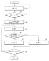
図4は本発明による携帯装置の制御方法を示したフローチャートである。
先ず、制御部150は待機状態である(210)。
この待機期間中、任意のアプリケーション、 プログラムまたはサービスを駆動中であることができる。ここで、 任意のアプリケーションは通話遂行のためのアプリケーションであることができる。
FIG. 4 is a flowchart illustrating a method for controlling a portable device according to the present invention.
First, the
During this waiting period, any application, program or service can be running. Here, the arbitrary application may be an application for performing a call.
待機状態で表示部170は電源がオン状態であることができる。すなわち、制御部150は待機状態で対応する画面を表示するように表示部170を制御することができる。表示部170に表示される画面は待機画面、アプリケーション駆動画面であることができ、 アプリケーションが通話遂行のためのアプリケーションの場合、 表示される画面は通話記録、電話番号リスト、ダイヤル画面の中のいずれか1つである。
In the standby state, the
次に、制御部150は通話イベントが発生したか否かを判断する(220)。
通話イベントは外部から通話遂行要請に対応するコールの受信又は通話遂行要請のための入力によって発生する。制御部150は通信部110を通じてコールが受信されたり、入力部120を通じて通話遂行要請に対応する入力が感知された場合、通話イベントが発生したと判断する。
Next, the
A call event is generated by receiving a call corresponding to a call execution request from the outside or by inputting a call execution request. When a call is received through the
制御部150は通話イベント発生と共に、 通話遂行のための情報を獲得する。例えば、制御部150は通話相手の電話番号、通話相手の位置情報、通話相手の基地局情報などを獲得する。制御部150は上記の情報を通信部110を通じて受信されたコールから獲得するか、又は、 入力部120を通じる使用者の入力によって獲得する。
The
通話イベントが発生すると、制御部150はイベント発生時の湿度を初期値として設定する(230)。
通話イベント発生時点は使用者が通話遂行のために携帯端末100を顔(特に、 耳部分) 辺りに持って行く直前の状態である。すなわち、通話イベント発生時に携帯端末100は使用者の人体に近接しない状態である。この時、使用者は表示部170に表示された情報を見ている状態である。したがって、制御部150は表示部170の電源をオンさせた状態で維持し、 現在表示中の画面を続けて表示するように制御する。
When a call event occurs, the
The time when the call event occurs is a state immediately before the user takes the
制御部150は通話イベント発生によって、 湿度センサー144を駆動させるための制御信号を湿度センサー144に伝達する。湿度センサー144は制御部150の制御信号によって湿度センサー144周辺の湿度を測定する。制御部150が通話イベント発生時点に湿度センサー144に制御信号を伝達し、 湿度センサー144は先ず通話イベント発生時の湿度を測定する。湿度センサー144は測定された湿度情報を含んだデータ信号を生成し、制御部150に伝達する。
The
制御部150は湿度センサー144から受信したデータ信号を基に、 通話イベント発生時の湿度を獲得する。
制御部150は獲得した通話イベント発生時の湿度を初期値として設定する。初期値は通話イベント発生以後の通話を行う間、湿度センサー144周辺の湿度が変わったか否か、及び湿度がどのくらい変化したかを判断するための基準になる値である。制御部150は図6に示したように通話発生時点で測定された湿度を初期値として設定する。
Based on the data signal received from the
The
制御部150は設定された初期値を貯蔵部160に臨時に貯蔵する。或いは制御部150は測定された湿度を表示するように表示部170を制御する。
同時に、制御部150は通話イベント発生による任意の動作を行うことができる。例えば、制御部150はコール受信音/コール発信音を出力したり、通話が行われていることを知らせる画面を表示するように携帯装置100の各構成要素を制御する。
The
At the same time, the
一方、通話イベントが発生しなければ、制御部150は待機モードへ戻り上記の過程を繰り返し行う。
On the other hand, if no call event occurs, the
次に、制御部150は湿度を測定する(240)。
制御部150は通話イベント発生によって要請された通話を行う。制御部150は通信部110を通じて繰り返し基地局又は通話相手と無線信号を交換して通話を行う。
制御部150は通話を行う間、湿度を測定する。制御部150は通話を行う間、湿度を測定するための制御信号を湿度センサー144に伝達する。制御部150は既設定された周期によって制御信号を生成して湿度センサー144に伝達する。湿度センサー144は制御部150の制御によって、既設定された周期によって湿度センサー144周辺の湿度を測定する。
Next, the
The
The
本発明の実施例によれば、 湿度センサー144は携帯装置100の音声入力部120と近接するように位置する。すなわち、湿度センサー144は図5に示されたように使用者が通話を行うために音声を入力する部位に位置する。使用者が通話を行うために携帯電話を顔、特に耳近所に位置させる場合、使用者の息づかいが湿度センサー144方向に放出される。使用者の息づかいには水分が含まれているので携帯装置100が使用者の顔に近接した場合、或いは使用者から音声入力部120を通じて音声入力を受ける場合、 湿度センサー144周辺の湿度は通話イベント発生時の湿度より上昇する。
According to the embodiment of the present invention, the
湿度センサー144は制御部150の制御によって、 既設定された周期によって湿度を測定する。湿度センサー144によって周期的に測定された湿度は図6に示すようなグラフで表される。制御部150はセンサー部144から測定された湿度情報を含むデータ信号を受信する。
The
次に、制御部150は湿度変化量が臨界変化量より大きいか同じであるか否かを、または湿度が臨界湿度より大きいか同じであるか否かを判断する(250)。
湿度変化量は任意の時間に測定された湿度と通話イベント発生時の湿度である初期値の間の差を意味する。湿度変化量を簡単な数式で示すと、以下の数1の同様である。
[数1]
湿度変化量 = 測定された湿度−初期値
Next, the
The amount of change in humidity means the difference between the humidity measured at an arbitrary time and the initial value, which is the humidity at the time of the call event. When the humidity change amount is represented by a simple mathematical expression, the following equation 1 is applied.
[Equation 1]
Humidity change = Measured humidity-Initial value
ここで初期値は通話イベント発生時の湿度である。
携帯装置100が使用者の顔に近接した場合、 湿度センサー144周辺の湿度は増加するので、湿度変化量は大きくなる。反対に、湿度センサー144が使用者の顔に近接するように位置しない場合、 周辺空気の水分量変動によって湿度センサー144周辺の湿度が変わることがあるが、 通話イベント発生時の湿度と大きな差がないから湿度変化量は少なくなる。
Here, the initial value is the humidity when the call event occurs.
When the
これによって、 湿度変化量が臨界変化量より大きいか同じ場合、或いは測定された湿度が臨界湿度より大きいか同じ場合、制御部150は表示部170をオフさせる(260)。
すなわち、湿度変化量が臨界変化量より大きいか同じ場合、或いは測定された湿度が臨界湿度より大きいか同じ場合、制御部150は図5に示すように携帯装置100が使用者の顔に近接したと判断する。このような場合に一般的に使用者は表示部170を見ていない。したがって、 制御部150は表示部170がオフされるように表示部170の電源を制御する。
Accordingly, if the humidity change amount is greater than or equal to the critical change amount, or if the measured humidity is greater than or equal to the critical humidity, the
That is, when the humidity change amount is greater than or equal to the critical change amount, or when the measured humidity is greater than or equal to the critical humidity, the
図6を参照すれば、通話中に周期的に湿度を測定し、湿度変化量が臨界変化量より大きいか同一であるとき、或いは測定された湿度が臨界湿度より大きいか同一であるとき表示部170がオフさせるようにする例をグラフで示した。 Referring to FIG. 6, when the humidity is periodically measured during a call and the humidity change amount is greater than or equal to the critical change amount, or when the measured humidity is greater than or equal to the critical humidity, the display unit An example in which 170 is turned off is shown in a graph.
このように本発明による携帯装置100の制御方法は、 通話中で使用者が実質的に携帯装置100を顔のあたりに位置させたり音声を入力すると感知される場合に、 表示部170の電源をオフすることによって、不必要な電力消費を阻止できる。
As described above, the control method of the
制御部150は表示部170がオフされることによって、ロックモード、節電モードまたはスリップモードに進入するように携帯装置100を制御する。または、制御部150は表示部170がオフされたことを知らせるためのアラーム、 振動などを出力することもできる。
When the
反対に、 湿度変化量が臨界変化量より小さな場合、または測定された湿度が臨界湿度より小さな場合、制御部150は表示部170をオンさせる(270)。
湿度変化量が臨界変化量より小さな場合、または測定された湿度が臨界湿度より小さい場合、 制御部150は携帯装置100が使用者の顔に近接しないと判断する。このような場合に使用者は表示部170を見ていることがあり得る。したがって、制御部150は表示部170がオンされるように表示部170の電源を制御する。
On the other hand, if the humidity change amount is smaller than the critical change amount, or if the measured humidity is smaller than the critical humidity, the
When the humidity change amount is smaller than the critical change amount, or when the measured humidity is smaller than the critical humidity, the
更に、 制御部150は通話終了イベントが発生したか否かを判断する (280)。
制御部150は通信部110を通じて通話終了のための無線信号が受信されたり、 入力部120を通じて通話終了のための入力が感知されると、通話終了イベントが発生したと判断する。
通話終了イベントが発生すると、制御部150は本発明による携帯装置100の制御動作を終了する。
Furthermore, the
The
When the call end event occurs, the
一方、通話終了イベントが発生しなければ、制御部150は湿度測定段階へ戻り上記過程を繰り返す。
上記では臨界変化量又は臨界湿度を基に通話中に湿度変化による表示部170のオン/オフを制御するいくつかの例を説明したが、これらに限定されず、本発明の技術思想を害しない範囲内で多様な変更が可能である。
On the other hand, if the call end event does not occur, the
In the above, some examples of controlling on / off of the
図7は本発明の他の実施例による携帯装置の制御方法を示したフローチャートである。
先ず、制御部150は待機状態である(310)。
この待機期間中、任意のアプリケーション、プログラム又はサービスを駆動中であることができる。ここで、 任意のアプリケーションは通話遂行のためのアプリケーションであることができる。
FIG. 7 is a flowchart illustrating a method for controlling a portable device according to another embodiment of the present invention.
First, the
During this waiting period, any application, program or service can be running. Here, the arbitrary application may be an application for performing a call.
待機状態で表示部170は電源がオンされた状態であることができる。すなわち、制御部150は待機状態で対応する画面を表示するように表示部170を制御することができる。表示部170に表示される画面は待機画面、アプリケーション駆動画面であることができ、アプリケーションが通話遂行のためのアプリケーションの場合、 表示される画面は通話記録、電話番号リスト、ダイヤル画面の中のいずれか1つである。
In the standby state, the
次に、制御部150は通話イベントが発生したか否かを判断する(320)。
Next, the
通話イベントが発生すると、 制御部150はイベント発生時の湿度を初期値として設定する(330)。
通話イベント発生時点は使用者が通話遂行のために携帯端末100を顔(特に、耳部分) 辺りに持って行く直前の状態である。すなわち、 通話イベント発生時に携帯端末100は使用者の人体に近接しない状態である。この時、 使用者は表示部170に表示された情報を見ている状態である。したがって、 制御部150は表示部170の電源をオンした状態で維持し、 現在表示中の画面を続けて表示するように制御する。
When a call event occurs, the
The time when the call event occurs is a state immediately before the user takes the
制御部150は通話イベント発生によって、 湿度センサー144を駆動させるための制御信号を湿度センサー144に伝達する。湿度センサー144は制御部150の制御信号によって湿度センサー144周辺の湿度を測定する。制御部150が通話イベント発生時点に湿度センサー144に制御信号を伝達し、 湿度センサー144は先ず通話イベント発生時の湿度を測定する。湿度センサー144は測定された湿度情報を含んだデータ信号を生成し、制御部150に伝達する。
The
制御部150は獲得した通話イベント発生時の湿度を初期値として設定する。初期値は通話イベント発生以後の通話を行う間、湿度センサー144周辺の湿度が変わったか否か及び湿度がどのくらい変化したかを判断するための基準となる値である。
The
制御部150は設定された初期値を貯蔵部160に臨時に貯蔵する。または制御部150は測定された湿度を表示するように表示部170を制御する。
The
一方、通話イベントが発生しなければ、制御部150は待機モードへ戻り上記の過程を繰り返し行う。
On the other hand, if no call event occurs, the
次に、制御部150は人体近接が認識されるか否かを判断する(340)。
制御部150は通話を行う間、携帯端末100が人体に近接したか否かを判断する。制御部150は人体に近接したか否かを判断するための制御信号を近接センサー143に伝達する。制御部150は既設定された周期によって制御信号を生成して近接センサー143に伝達する。近接センサー143は制御部150の制御によって、 既設定された周期によって携帯端末100に人体が近接したか否かを判断する。
Next, the
The
本発明の実施例によれば、近接センサー143は図8に示したように携帯装置100の前面部に配置される。すなわち、近接センサー143は通話のために使用者が携帯装置100を顔に近接するように位置させた時、 使用者の顔と触れ合うようになる携帯装置100の前面部に配置される。これによって、近接センサー143は通話を行う間使用者の顔(特に、頬又は耳)が近接したか否かを感知する。人体の近接が感知されると、近接センサー143はこれに対応する制御信号を生成して制御部150に伝達する。
According to the embodiment of the present invention, the
制御部150は近接センサー143から伝達された制御信号を基に、 携帯端末100に人体が近接したか否かを判断する。
Based on the control signal transmitted from the
人体の近接が感知されると、制御部150は表示部170をオフさせる(350)。
人体の近接が感知されると、 制御部150は使用者が表示部170を見ていなく、図8 に示されたように通話を遂行中と判断する。したがって、制御部150は表示部170がオフされるように表示部170の電源を制御する。
When the proximity of the human body is detected, the
When the proximity of the human body is detected, the
制御部150は表示部170がオフすることによって、ロックモード、 節電モード又はスリップモードに進入するように携帯装置100を制御する。または、制御部150は表示部170がオフされたことを知らせるためのアラーム、振動などを出力することもできる。
When the
反対に、人体の近接が感知されない場合、制御部150は湿度を測定する(360)。
人体の近接が感知されない場合は使用者は表示部170を見ている場合であるか、又は、 通話を行わない場合である。しかし、近接センサー143が故障したり誤作動を起こす場合に人体が実質的に携帯装置100に近接したにもかかわらず、 人体の近接を感知することができないことがある 。
On the other hand, if proximity of the human body is not sensed, the
When the proximity of the human body is not detected, the user is looking at the
したがって、本発明の実施例によれば、近接センサー143が故障したり誤作動する場合に対応し、湿度センサー144を補助手段として使用する。
Therefore, according to the embodiment of the present invention, the
具体的に、 制御部150は近接センサー143を通じて人体の近接が感知されなければ湿度を測定するための制御信号を湿度センサー144に伝達する。制御部150は既設定された周期によって制御信号を生成して湿度センサー144に伝達する。湿度センサー144は制御部150の制御によって、既に設定された周期によって湿度センサー144周辺の湿度を測定する。
Specifically, if the proximity of the human body is not detected through the
本発明の実施例によれば、 湿度センサー144は携帯装置100の音声入力部120と近接するように位置する。すなわち、湿度センサー144は図5に示されたように使用者が通話を行うために音声を入力する部位に位置する。使用者が通話を行うために携帯電話を顔、特に耳近所に位置させる場合、使用者の息づかいが湿度センサー144方向に放出される。使用者の息づかいには水分が含まれているので携帯装置100が使用者の顔に近接した場合、或いは使用者から音声入力部120を通じて音声を受ける場合、 湿度センサー144周辺の湿度は通話イベント発生時の湿度より上昇する。
According to the embodiment of the present invention, the
湿度センサー部144は制御部150の制御によって、 既設定された周期によって湿度を測定する。湿度センサー144によって周期的に測定された湿度は図6に示されたようなグラフで表される。制御部150は湿度センサー部144から測定された湿度情報を含むデータ信号を受信する。
The
次に、制御部150は湿度変化量が臨界変化量より大きいか同じであるか否かを、または湿度が臨界湿度より大きいか同じであるか否かを判断する(370)。
Next, the
湿度変化量は任意の時間に測定された湿度と通話イベント発生時の湿度である初期値の間の差を意味する。湿度変化量を簡単な数式で示すと、以下の数2である。
[数2]
湿度変化量 = 測定された湿度−初期値
The amount of change in humidity means the difference between the humidity measured at an arbitrary time and the initial value, which is the humidity at the time of the call event. The humidity change amount is expressed by the following formula 2 by a simple mathematical expression.
[Equation 2]
Humidity change = Measured humidity-Initial value
携帯装置100が使用者の顔に近接した場合、 湿度センサー144周辺の湿度は増加するので、湿度変化量は大きくなる。反対に、湿度センサー144が使用者の顔に近接するように位置しない場合、 周辺空気の水分量変動によって湿度センサー144周辺の湿度が変わることがありえるが、 通話イベント発生時の湿度と大きい差がないので湿度変化量は少なくなる。
When the
臨界変化量は携帯装置100が使用者の顔に近接したと判断するための湿度変化量の臨界を意味する。臨界変化量は図6に示されたように、測定された湿度と初期値の間の差で表現される。
The critical change amount means a critical amount of humidity change for determining that the
任意の時間に測定された湿度と初期値の間の差である湿度変化量が臨界変化量より大きいか同じであれば、 制御部150は携帯装置100が使用者の顔に近接したと判断し、結果的に使用者が通話遂行中と判断する。反対に、 湿度変化量が臨界変化量より小さければ、 制御部150は携帯装置100が使用者の顔に近接しないと判断し、結果的に使用者が通話を行わないか表示部170を見ていると判断する。
If the humidity change amount, which is the difference between the humidity measured at an arbitrary time and the initial value, is greater than or equal to the critical change amount, the
臨界変化量は携帯端末100の製造の時に予め設定されたり使用者の入力によって設定されることができる。臨界変化量は使用者が通話遂行の時、湿度センサー144で発生する湿度の変化を測定した実験データを基に精緻に決定されることができる。
The critical change amount can be set in advance when the
これによって、 湿度変化量が臨界変化量より大きいか同じ場合、或いは測定された湿度が臨界湿度より大きいか同じ場合、制御部150は表示部170をオフさせる(350)。
Accordingly, if the humidity change amount is greater than or equal to the critical change amount, or if the measured humidity is greater than or equal to the critical humidity, the
反対に、 湿度変化量が臨界変化量より小さな場合または測定された湿度が臨界湿度より小さな場合、制御部150は表示部170をオンさせる(380)。
On the contrary, if the humidity change amount is smaller than the critical change amount or the measured humidity is smaller than the critical humidity, the
更に、 制御部150は通話終了イベントが発生したのか否かを判断する (390)。
Further, the
制御部150は通信部110を通じて通話終了のための無線信号が受信されたり、入力部120を通じて通話終了のための入力が感知されると、 通話終了イベントが発生したと判断する。
通話終了イベントが発生すると、 制御部150は本発明による携帯装置100の制御動作を終了する。
When a wireless signal for ending a call is received through the
When the call end event occurs, the
一方、通話終了イベントが発生しなければ、制御部150は人体近接が感知されたか否かを判断する段階へ戻り上記過程を繰り返す。
On the other hand, if the call end event does not occur, the
本発明が属する技術分野で通常の知識を有する者であれば本発明の本質的な特性から外れない範囲で多様な修正及び変形が可能であろう。したがって、本発明に開示された実施例は本発明の技術思想を限定するためではなく説明するためのもので、 このような実施例によって本発明の技術思想の範囲が限定されるものではない。本発明の保護範囲は請求範囲によって解釈されるべきで、それと同等な範囲内にあるすべての技術思想は本発明の権利範囲に含まれると解釈されるべきであろう。 Those skilled in the art to which the present invention pertains can make various modifications and variations without departing from the essential characteristics of the present invention. Therefore, the embodiments disclosed in the present invention are not intended to limit the technical idea of the present invention, but to explain them, and the scope of the technical idea of the present invention is not limited by such examples. The protection scope of the present invention should be construed by the claims, and all technical ideas within the equivalent scope should be construed as being included in the scope of the present invention.
100;携帯装置
110;通信部
120;入力部
130;音声入力部
140;センサー部
150;制御部
160;貯蔵部
170;表示部
100;
Claims (15)
通話イベントが発生すると、 前記湿度センサーを用いて前記携帯装置周辺の湿度を測定する段階と、
前記測定された湿度を既設定された臨界値と比べる段階と、
比較結果によって前記携帯装置の表示部のオン/オフを選択的に制御する段階と、を含むことを特徴とする携帯装置の制御方法。 A method for controlling a portable device comprising a humidity sensor,
When a call event occurs, measuring the humidity around the portable device using the humidity sensor;
Comparing the measured humidity with a preset critical value;
And a step of selectively controlling on / off of the display unit of the portable device according to the comparison result.
前記測定された湿度が前記臨界湿度より大きいか同じであるか否かを判断する段階を含むことを特徴とする、請求項1に記載の携帯装置の制御方法。 The comparing step includes
The method of claim 1, further comprising determining whether the measured humidity is greater than or equal to the critical humidity.
前記測定された湿度が前記臨界湿度より大きいか同じであれば前記表示部をオフし、前記測定された湿度が前記臨界湿度より小さければ前記表示部をオンする段階を含むことを特徴とする、請求項2に記載の携帯装置の制御方法。 Selectively controlling on / off of the display unit includes:
If the measured humidity is greater than or equal to the critical humidity, the display unit is turned off.If the measured humidity is lower than the critical humidity, the display unit is turned on. The method for controlling a portable device according to claim 2.
前記通話イベント発生時の湿度を初期値として設定する段階を含むことを特徴とする、請求項1に記載の携帯装置の制御方法。 The step of measuring the humidity comprises:
The method for controlling a portable device according to claim 1, further comprising: setting a humidity at the time of the occurrence of the call event as an initial value.
前記測定された湿度と前記初期値の差である湿度変化量が、臨界変化量より大きいか同じであるか否かを判断する段階を含むことを特徴とする、請求項4に記載の携帯装置の制御方法。 The comparing step includes
5. The portable device according to claim 4, further comprising determining whether a humidity change amount that is a difference between the measured humidity and the initial value is greater than or equal to a critical change amount. Control method.
前記通話イベントが発生すると、 近接センサーを用いて前記携帯装置に使用者の人体が近接したか否かを判断する段階と、
その判断の結果、前記携帯装置に前記使用者の人体が近接しない場合、前記携帯装置周辺の湿度を測定する段階と、を含むことを特徴とする、請求項1に記載の携帯装置の制御方法。 The step of measuring the humidity comprises:
When the call event occurs, determining whether a user's human body is in proximity to the portable device using a proximity sensor;
The method for controlling a portable device according to claim 1, further comprising a step of measuring humidity around the portable device when the human body of the user is not in proximity to the portable device as a result of the determination. .
前記携帯装置の内部で音声入力部と近接するように設置されることを特徴とする、請求項1に記載の携帯装置の制御方法。 The humidity sensor
The method of controlling a portable device according to claim 1, wherein the portable device is installed so as to be close to a voice input unit inside the portable device.
前記近接センサーが動作可能ではなければ、 前記湿度センサーを使用した前記比較結果によって前記表示部のオン/オフを選択的に制御する段階をさらに含むことを特徴とする、請求項6に記載の携帯装置の制御方法。 Determining whether the proximity sensor is operable;
The mobile phone of claim 6, further comprising selectively controlling on / off of the display unit according to the comparison result using the humidity sensor if the proximity sensor is not operable. Control method of the device.
情報を表示する表示部と、
前記測定された湿度を既設定された臨界値と比べて、 その比較結果によって前記表示部のオン/オフを制御する制御部と、を含むことを特徴とする携帯装置。 When a call event occurs, a humidity sensor that measures the humidity around the mobile device while making a call,
A display for displaying information;
A portable device comprising: a control unit that compares the measured humidity with a preset critical value and controls on / off of the display unit according to a comparison result.
前記測定された湿度が、前記臨界湿度より大きいか同じであるか否かを判断することを特徴とする、請求項9に記載の携帯装置。 The controller is
The portable device according to claim 9, wherein it is determined whether the measured humidity is greater than or equal to the critical humidity.
前記測定された湿度が前記臨界湿度より大きいか同じであれば前記表示部がオフするように制御し、 前記測定された湿度が前記臨界湿度より小さければ前記表示部がオンするように制御することを特徴とする、請求項10に記載の携帯装置。 The controller is
If the measured humidity is greater than or equal to the critical humidity, the display unit is controlled to be turned off, and if the measured humidity is smaller than the critical humidity, the display unit is controlled to be turned on. The portable device according to claim 10, wherein:
前記通話イベント発生時の湿度を初期値として設定することを特徴とする、 請求項9に記載の携帯装置。 The controller is
The mobile device according to claim 9, wherein the humidity at the occurrence of the call event is set as an initial value.
前記制御部は、
前記通話イベントが発生すると、前記近接センサーを用いて前記人体の近接が感知されたか否かを判断し、前記人体の近接が感知されない場合、前記携帯装置の周辺の湿度を測定するように前記湿度センサーを制御することを特徴とする、 請求項11に記載の携帯装置。 It further includes a proximity sensor that senses the proximity of the human body,
The controller is
When the call event occurs, the proximity sensor is used to determine whether the proximity of the human body is sensed. When the proximity of the human body is not sensed, the humidity is measured so as to measure the humidity around the portable device. The portable device according to claim 11, wherein the sensor is controlled.
前記音声入力部を取り囲み、外部の空気流入のためのホールが形成されたケースをさらに含み、
前記湿度センサーは、
前記ケースの内部で前記音声入力部と近接するように設置されることを特徴とする、請求項11に記載の携帯装置。 A voice input unit that receives a voice input of a user; and a case that surrounds the voice input unit and that has a hole formed for external air inflow;
The humidity sensor
The portable device according to claim 11, wherein the portable device is installed in the case so as to be close to the voice input unit.
Applications Claiming Priority (2)
| Application Number | Priority Date | Filing Date | Title |
|---|---|---|---|
| KR1020120132221A KR102070116B1 (en) | 2012-11-21 | 2012-11-21 | Method for controlling portable device by using humidity sensor and portable device thereof |
| KR10-2012-0132221 | 2012-11-21 |
Publications (2)
| Publication Number | Publication Date |
|---|---|
| JP2014103655A true JP2014103655A (en) | 2014-06-05 |
| JP6335447B2 JP6335447B2 (en) | 2018-05-30 |
Family
ID=48703154
Family Applications (1)
| Application Number | Title | Priority Date | Filing Date |
|---|---|---|---|
| JP2013147995A Expired - Fee Related JP6335447B2 (en) | 2012-11-21 | 2013-07-16 | Method for controlling portable device using humidity sensor and portable device |
Country Status (5)
| Country | Link |
|---|---|
| US (1) | US8983444B2 (en) |
| EP (1) | EP2736233B1 (en) |
| JP (1) | JP6335447B2 (en) |
| KR (1) | KR102070116B1 (en) |
| CN (1) | CN103841258B (en) |
Cited By (3)
| Publication number | Priority date | Publication date | Assignee | Title |
|---|---|---|---|---|
| JP2016051919A (en) * | 2014-08-28 | 2016-04-11 | 富士通株式会社 | Wireless communication device |
| JP2017069651A (en) * | 2015-09-28 | 2017-04-06 | 京セラ株式会社 | Electronic device, control method, and control program |
| JP2019103145A (en) * | 2017-12-05 | 2019-06-24 | 三星電子株式会社Samsung Electronics Co.,Ltd. | Electronic device and method for making the electronic device operate |
Families Citing this family (8)
| Publication number | Priority date | Publication date | Assignee | Title |
|---|---|---|---|---|
| US9176089B2 (en) * | 2013-03-29 | 2015-11-03 | Stmicroelectronics Pte Ltd. | Integrated multi-sensor module |
| CN104010059B (en) * | 2014-06-09 | 2018-08-07 | 努比亚技术有限公司 | A kind of mobile terminal and its realize the method and apparatus made a phone call |
| JP2015232654A (en) * | 2014-06-10 | 2015-12-24 | セイコーエプソン株式会社 | Exhalation detection device, portable terminal and time display device |
| US10678310B2 (en) | 2016-11-23 | 2020-06-09 | Mobelisk Group, Llc | Modular tablet case with environmental monitoring components |
| US10653361B2 (en) * | 2017-05-18 | 2020-05-19 | Motorola Mobility Llc | Breath sensory on a mobile communication device |
| CN107736874B (en) * | 2017-08-25 | 2020-11-20 | 百度在线网络技术(北京)有限公司 | Living body detection method, living body detection device, living body detection equipment and computer storage medium |
| CN116420132A (en) | 2020-11-06 | 2023-07-11 | 三星电子株式会社 | Electronic device for sensing moisture introduction and method of operating the same |
| KR20220061733A (en) * | 2020-11-06 | 2022-05-13 | 삼성전자주식회사 | Electronic device for detecting moisture inflow and method for operating thereof |
Citations (7)
| Publication number | Priority date | Publication date | Assignee | Title |
|---|---|---|---|---|
| JP2006260091A (en) * | 2005-03-16 | 2006-09-28 | Fuji Xerox Co Ltd | Information processing system, information processor and display medium |
| US20110003614A1 (en) * | 2009-07-02 | 2011-01-06 | Nxp B.V. | Proximity sensor, in particular microphone for reception of sound signals in the human audible sound range, with ultrasonic proximity estimation |
| JP2011518371A (en) * | 2008-03-26 | 2011-06-23 | ピエール・ボナ | Method and system for processing a MEMS detector signal that allows control of the device using human exhalation |
| JP2012029217A (en) * | 2010-07-27 | 2012-02-09 | Kyocera Corp | Portable terminal device |
| EP2479892A1 (en) * | 2011-01-19 | 2012-07-25 | Sensirion AG | Input device |
| JP2012186620A (en) * | 2011-03-04 | 2012-09-27 | Nec Casio Mobile Communications Ltd | Display device, display control method, and program |
| US20120270611A1 (en) * | 2011-04-19 | 2012-10-25 | Samsung Electronics Co., Ltd. | Method for controlling mobile terminal |
Family Cites Families (5)
| Publication number | Priority date | Publication date | Assignee | Title |
|---|---|---|---|---|
| US20050219228A1 (en) | 2004-03-31 | 2005-10-06 | Motorola, Inc. | Intuitive user interface and method |
| CN102176733A (en) * | 2011-01-28 | 2011-09-07 | 宇龙计算机通信科技(深圳)有限公司 | Method, system and mobile terminal for controlling screen backlight |
| US9117395B2 (en) * | 2011-04-19 | 2015-08-25 | Samsung Electronics Co., Ltd | Method and apparatus for defining overlay region of user interface control |
| CN102158609A (en) * | 2011-05-09 | 2011-08-17 | 惠州Tcl移动通信有限公司 | Wireless communication equipment and method for controlling backlight, touch screen and keyboard |
| US9288840B2 (en) * | 2012-06-27 | 2016-03-15 | Lg Electronics Inc. | Mobile terminal and controlling method thereof using a blowing action |
-
2012
- 2012-11-21 KR KR1020120132221A patent/KR102070116B1/en not_active Expired - Fee Related
-
2013
- 2013-04-24 US US13/869,282 patent/US8983444B2/en not_active Expired - Fee Related
- 2013-06-19 EP EP13172883.4A patent/EP2736233B1/en not_active Not-in-force
- 2013-07-04 CN CN201310278256.4A patent/CN103841258B/en not_active Expired - Fee Related
- 2013-07-16 JP JP2013147995A patent/JP6335447B2/en not_active Expired - Fee Related
Patent Citations (7)
| Publication number | Priority date | Publication date | Assignee | Title |
|---|---|---|---|---|
| JP2006260091A (en) * | 2005-03-16 | 2006-09-28 | Fuji Xerox Co Ltd | Information processing system, information processor and display medium |
| JP2011518371A (en) * | 2008-03-26 | 2011-06-23 | ピエール・ボナ | Method and system for processing a MEMS detector signal that allows control of the device using human exhalation |
| US20110003614A1 (en) * | 2009-07-02 | 2011-01-06 | Nxp B.V. | Proximity sensor, in particular microphone for reception of sound signals in the human audible sound range, with ultrasonic proximity estimation |
| JP2012029217A (en) * | 2010-07-27 | 2012-02-09 | Kyocera Corp | Portable terminal device |
| EP2479892A1 (en) * | 2011-01-19 | 2012-07-25 | Sensirion AG | Input device |
| JP2012186620A (en) * | 2011-03-04 | 2012-09-27 | Nec Casio Mobile Communications Ltd | Display device, display control method, and program |
| US20120270611A1 (en) * | 2011-04-19 | 2012-10-25 | Samsung Electronics Co., Ltd. | Method for controlling mobile terminal |
Cited By (4)
| Publication number | Priority date | Publication date | Assignee | Title |
|---|---|---|---|---|
| JP2016051919A (en) * | 2014-08-28 | 2016-04-11 | 富士通株式会社 | Wireless communication device |
| JP2017069651A (en) * | 2015-09-28 | 2017-04-06 | 京セラ株式会社 | Electronic device, control method, and control program |
| JP2019103145A (en) * | 2017-12-05 | 2019-06-24 | 三星電子株式会社Samsung Electronics Co.,Ltd. | Electronic device and method for making the electronic device operate |
| JP7506456B2 (en) | 2017-12-05 | 2024-06-26 | 三星電子株式会社 | ELECTRONIC DEVICE AND METHOD FOR OPERATING AN ELECTRONIC DEVICE - Patent application |
Also Published As
| Publication number | Publication date |
|---|---|
| JP6335447B2 (en) | 2018-05-30 |
| EP2736233A1 (en) | 2014-05-28 |
| US20140141761A1 (en) | 2014-05-22 |
| CN103841258A (en) | 2014-06-04 |
| CN103841258B (en) | 2018-04-10 |
| KR102070116B1 (en) | 2020-01-28 |
| US8983444B2 (en) | 2015-03-17 |
| EP2736233B1 (en) | 2018-10-24 |
| KR20140065107A (en) | 2014-05-29 |
Similar Documents
| Publication | Publication Date | Title |
|---|---|---|
| JP6335447B2 (en) | Method for controlling portable device using humidity sensor and portable device | |
| KR102229006B1 (en) | Method and apparatus for processing input using touch screen | |
| US10860084B2 (en) | Method and apparatus for reducing power consumption based on use pattern of user | |
| CN110413315B (en) | Application control method and electronic device | |
| US10067666B2 (en) | User terminal device and method for controlling the same | |
| KR20140004846A (en) | Method and apparatus for controlling flexible display panel | |
| CN106527785B (en) | Mobile terminal and control method for the same | |
| US20150100813A1 (en) | Method and device for processing images to save power | |
| US20120019456A1 (en) | Method for executing private mode in mobile terminal and mobile terminal using the same | |
| KR20110137190A (en) | Power management method of mobile communication terminal and mobile communication terminal using same | |
| US20150323963A1 (en) | Device and method of controlling a display panel based on cover-related information | |
| US20140340336A1 (en) | Portable terminal and method for controlling touch screen and system thereof | |
| JP2018160239A (en) | Touch input device and control method thereof | |
| KR20190050624A (en) | Electronic device for providing time information and a method for the same | |
| JP2013258478A (en) | Portable electronic apparatus, input operation control method, and program | |
| KR20150061420A (en) | Smart watch and operation method thereof | |
| KR20140137081A (en) | Status change control and executing functions method and electronic device supporting the same | |
| KR20150019805A (en) | Controlling Method For Input Status and Electronic Device supporting the same | |
| CN110431518B (en) | Method and electronic device for outputting touch signal | |
| WO2015002300A1 (en) | Portable terminal and control method | |
| KR102685801B1 (en) | Electronic device for preventing unintended user input by using an illuminance sensor and a display and method for the same | |
| CN114144749A (en) | Operation method based on touch input and electronic device thereof | |
| CN108965576A (en) | Incoming call processing method and device, storage medium and electronic equipment | |
| CN107765833A (en) | A kind of alarm clock prompting method and mobile terminal | |
| JP6306345B2 (en) | Electronics |
Legal Events
| Date | Code | Title | Description |
|---|---|---|---|
| A621 | Written request for application examination |
Free format text: JAPANESE INTERMEDIATE CODE: A621 Effective date: 20160711 |
|
| A131 | Notification of reasons for refusal |
Free format text: JAPANESE INTERMEDIATE CODE: A131 Effective date: 20170829 |
|
| A521 | Request for written amendment filed |
Free format text: JAPANESE INTERMEDIATE CODE: A523 Effective date: 20171124 |
|
| TRDD | Decision of grant or rejection written | ||
| A01 | Written decision to grant a patent or to grant a registration (utility model) |
Free format text: JAPANESE INTERMEDIATE CODE: A01 Effective date: 20180424 |
|
| A61 | First payment of annual fees (during grant procedure) |
Free format text: JAPANESE INTERMEDIATE CODE: A61 Effective date: 20180501 |
|
| R150 | Certificate of patent or registration of utility model |
Ref document number: 6335447 Country of ref document: JP Free format text: JAPANESE INTERMEDIATE CODE: R150 |
|
| LAPS | Cancellation because of no payment of annual fees |