JP2014103106A - Halogen lamp for automobile headlight - Google Patents
Halogen lamp for automobile headlight Download PDFInfo
- Publication number
- JP2014103106A JP2014103106A JP2013218930A JP2013218930A JP2014103106A JP 2014103106 A JP2014103106 A JP 2014103106A JP 2013218930 A JP2013218930 A JP 2013218930A JP 2013218930 A JP2013218930 A JP 2013218930A JP 2014103106 A JP2014103106 A JP 2014103106A
- Authority
- JP
- Japan
- Prior art keywords
- bulb
- light
- halogen lamp
- light shielding
- filament
- Prior art date
- Legal status (The legal status is an assumption and is not a legal conclusion. Google has not performed a legal analysis and makes no representation as to the accuracy of the status listed.)
- Pending
Links
Images


Abstract
Description
本発明は、バルブ内にロービーム用フィラメントと、ハイビーム用フィラメントとを収容するH4タイプの自動車前照灯用ハロゲンランプに関する。 The present invention relates to a halogen lamp for an automotive headlamp of H4 type in which a low beam filament and a high beam filament are accommodated in a bulb.
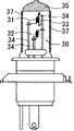
従来のH4タイプの自動車前照灯用ハロゲンランプとして特開平9−330685号公報では図4に示す様に、石英ガラス等の耐熱性で透明なバルブ30内に中心軸に平行にロービーム用フィラメント31とハイビーム用フィラメント32とが設けられ、ロービーム用フィラメント31にはミラー33からなる遮光体が取り付けられている。そして、バルブ30の外表面には、少なくとも一層以上の酸化ケイ素と酸化コバルト,あるいは酸化ケイ素と酸化コバルトと燐酸化物の複合酸化物からなる青色着色膜層を積層してなる青色着色膜37を形成して、色むらのない高純度の白色光を放射するハロゲン電球が開示されている。
As a conventional halogen lamp for H4 type automobile headlamps, Japanese Patent Laid-Open No. 9-330685 discloses a low-
また、特開平11−176390号公報では図5に示す様に、石英ガラス等の耐熱性で透明なバルブ30内に中心軸に平行にロービーム用フィラメント31とハイビーム用フィラメント32とが設けられ、ロービーム用フィラメント31にはミラー33からなる遮光体が取り付けられている。そして、バルブの外表面には、少なくとも1層以上の酸化ケイ素と酸化コバルトと燐酸化物の複合酸化物からなる青色着色膜層を積層してなる高色温度型色温度変換膜からなる着色膜37を形成し、更にその上に酸化チタンからなる高屈折率層と酸化ケイ素からなる低屈折率層を交互に積層してなる多層干渉膜38を設け、色温度を一層高めたハロゲン電球が開示されている。
In Japanese Patent Laid-Open No. 11-176390, as shown in FIG. 5, a
しかしながら、前記特開平9−330685号公報や、特開平11−176390号公報に開示されるバルブ構造では、ロービームフィラメント31下部のミラー33によりロービームフィラメント31から発する光が拡散され、ロービームフィラメント31の輝度が低下する為、保安基準第32条に記載されている光度測定点に照射光が集光しづらくなり、光度値が低下してしまう特性があり、このバルブ構造にて青色着色膜37を濃く、特に若年層ユーザに好まれるよう発光色の色温度6000K以上とすると、バルブ透過率低下により、保安基準第32条に記載されている光度規格を満たすことができなかった。
However, in the bulb structure disclosed in Japanese Patent Laid-Open Nos. 9-330685 and 11-176390, the light emitted from the
また、バルブ30の外表面に青色着色膜37を形成した場合には、ロービーム用フィラメント31から照射された可視光の中の主に長波長光と赤外線が青色着色膜37で吸収されて熱エネルギーに変換されるため、青色着色膜37が形成されていないクリアのバルブよりもバルブ30の表面およびバルブ30の内部温度が高くなる。
Further, when the blue colored
しかしながら、自動車前照灯用ハロゲンランプは一般的に横向きで点灯させるため、ランプ点灯中はバルブ30の上半部が高温となり、バルブ30の下部と先端部の温度が相対的に低くなるが、ミラー33がバルブ30内のロービーム用フィラメント31の下部に存在すると、ロービーム用フィラメント31からの照射光(赤外線を含む)がバルブ30の下部に届かず、バルブ30の下部の温度が他の部分に対して極端に低くなり、このためにハロゲンサイクルが不均等となり、バルブ30の下部に付着析出したタングステンが蒸発せず蓄積し、結果としてロービーム用フィラメント31に戻るべきタングステンが、十分に戻らないためにバルブ内面が黒化して、照度低下、配光異常を生じさせるケースがあった。さらに青色着色膜37が濃い場合、バルブ黒化によりバルブ温度がさらに上昇し、結果、青色着色膜37の熱劣化による剥離が発生する。さらに上半部、下半部のバルブ温度差に加え、バルブ黒化によるバルブ温度上昇により、バルブ温度ムラが大きくなる事で、封入ガス圧によっては残留歪が生じ、バルブが破損する不具合が生じる。
However, since halogen lamps for automobile headlamps are generally lit sideways, the upper half of the
前記従来技術の欠点を解消可能な技術として、特開平6−13058号公報では図6に示す様に、直管形バルブ40の両端を封止するとともに、前記バルブ40内に、複数本のフィラメント41、42を直列に接続してバルブ中心軸上に収容し、前記複数本のフィラメント41、42を選択的に発光させるようにしたことを特徴とする管形白熱電球において、車両の前照灯として使用するため前記バルブ40の外面の一部に、配光を制御するための可視光反射膜46を有し、かつ赤外反射膜によるフィラメント発光効率を向上できる管形白熱電球が開示されている。
As a technique capable of eliminating the disadvantages of the prior art, as shown in FIG. 6 in Japanese Patent Laid-Open No. 6-13058, both ends of a straight tube valve 40 are sealed, and a plurality of filaments are contained in the valve 40. 41. A tubular incandescent bulb characterized in that 41 and 42 are connected in series and accommodated on the central axis of the bulb so that the plurality of filaments 41 and 42 emit light selectively. A tube-type incandescent bulb having a visible
また、特開平7−220697号公報では、図7に示す様に、赤外線反射膜57が形成された球面部を有するバルブ50内にロービーム用フィラメント51とハイビーム用フィラメント52とを収容した白熱電球において、前記バルブ50に前記ロービーム用フィラメント51から特定方向に向けて放出された可視光を反射する可視光反射膜56を形成し、赤外線帰還によりフィラメント発光効率が改善された白熱電球が開示されている。
JP-A-7-220697 discloses an incandescent lamp in which a
特開平6−13058号公報に記載の技術では、バルブ内に遮光体を用いないため、遮光体によってバルブ40の下部への照射光が遮られバルブ40の下部の温度が極端に低くなる事は防止できる。しかしバルブ40の径を小さくする事でバルブ40の温度が上昇するが、青色着色を施す事でさらにバルブ40温度が上昇し、青色着色が剥離してしまう不具合と、ハロゲンバルブで一般的に使用される軟化点が低いガラス(例えばPhilips製PH511)では、青色着色が濃い場合はバルブ40の上部が膨張してしまう不具合が生じる。これを防ぐためにバルブ径を大きくし、バルブ温度を低下させると既存のバルブより長尺になってしまい、車両によっては取り付けられない不具合が生じる。また軟化点が高いガラスを使用すると加工工数が著しく増加する。 In the technique described in Japanese Patent Application Laid-Open No. 6-13058, a light shield is not used in the bulb, so that the light irradiated to the lower portion of the bulb 40 is blocked by the shade and the temperature at the lower portion of the bulb 40 becomes extremely low. Can be prevented. However, reducing the diameter of the bulb 40 increases the temperature of the bulb 40. However, the blue coloration further increases the temperature of the bulb 40, causing the blue color to peel off, and is generally used for halogen bulbs. In a glass having a low softening point (for example, PH511 manufactured by Philips), there is a problem that the upper portion of the bulb 40 expands when the blue coloration is dark. In order to prevent this, if the valve diameter is increased and the valve temperature is lowered, the valve becomes longer than the existing valve, which causes a problem that it cannot be attached depending on the vehicle. Further, when glass having a high softening point is used, the number of processing steps increases remarkably.
前記特開平7−220697号公報では、赤外線反射膜57が形成された球面部を有するバルブ50の外面には一部に、配光を制御するための可視光反射膜56を形成する。
In JP-A-7-220697, a visible
しかし可視光反射膜56により、反射された可視光はバルブ下部からサブフィラメントを経由して上部に向かって反射する為、フィラメント輝度が低下し、結果、保安基準第32条に記載されている光度測定点に照射光が集光しづらくなり、光度値が低下してしまう特性がある。また、バルブに球面部を有する事で青色着色膜をディッピングで塗布する際、直管型バルブに対し、球面部形成時の形状ばらつきにより色ムラ、液だまりが生じやすくなり、結果発光色にばらつきが生じ、商品価値が低下する。さらに球面部を形成する際の寸法ばらつきにより、下部に遮光膜を形成する際も留意しないと、遮光膜位置ずれにより配光異常を生じるので、製造工数がかかる。さらに高温のフィラメント近傍に球面部を形成する事は、成形時に生じるガラス歪にも留意しなくてはならず、検査、歪除去の工数がかかる。
However, since the visible light reflected by the visible
本発明は、前記従来技術の欠点を解消して、発光色が日本工業規格JIS−D5500の白色範囲内で、視認性、ファッション性の優れる色温度4500K〜6700Kの発光とできるランプを安価に製造し、更にロービーム下部の遮光体による輝度低下を回避して照射集光効率を高め、バルブ表面の温度を均一化するとともにバルブ内面の温度を上げてハロゲンサイクルを均一化させることにより黒化を低減し、耐久性に優れたH4タイプの自動車前照灯用ハロゲンランプを提供可能とすることを課題とする。 The present invention eliminates the drawbacks of the prior art, and manufactures a lamp capable of emitting light at a color temperature of 4500K to 6700K with excellent emission and visibility within the white range of Japanese Industrial Standard JIS-D5500. In addition, brightness reduction due to the light shielding body under the low beam is avoided to increase the light collection efficiency, and the bulb surface temperature is made uniform, and the bulb inner surface temperature is raised to make the halogen cycle uniform, thereby reducing blackening. It is another object of the present invention to provide an H4 type halogen lamp for an automotive headlamp that is excellent in durability.
本発明の自動車前照灯用ハロゲンランプは、バルブ内にロービーム用フィラメントと、ハイビーム用フィラメントとを収容するH4タイプの自動車前照灯用ハロゲンランプにおいて、発光色が日本工業規格JIS−D5500の白色範囲内であり、色温度が4500Kから6700Kの発光が得られるようにバルブの光透過部外面に着色膜を形成し、使用状態におけるバルブ内のロービームフィラメントの下部位置に遮光体を有さず、バルブ外の少なくともロービームフィラメントの下部位置にフィラメント発光を反射しない遮光手段を配置したことを特徴とする。 The halogen lamp for automobile headlamps according to the present invention is a halogen lamp for H4 type automobile headlamps in which a low beam filament and a high beam filament are accommodated in a bulb, and the emission color is white of Japanese Industrial Standard JIS-D5500. A colored film is formed on the outer surface of the light transmitting portion of the bulb so that light emission of 4500K to 6700K is obtained within the range, and there is no light shield at the lower position of the low beam filament in the bulb in use, A light-shielding means that does not reflect the emission of the filament is disposed at least below the low-beam filament outside the bulb.
更に、前記遮光手段がバルブの外側に塗布した遮光膜であることを特徴とする。 Further, the light shielding means is a light shielding film coated on the outside of the bulb.
更に、前記遮光膜の厚みが0.5mm以下であることを特徴とする。 Furthermore, the thickness of the light shielding film is 0.5 mm or less.
また、前記遮光手段がバルブの外側において、前記バルブと間隔をおいて配置した遮光板であることを特徴とする。 The light-shielding means is a light-shielding plate disposed outside the bulb and spaced from the bulb.
更に、前記遮光板はバルブの頂部を覆うキャップ部分と、バルブの少なくともロービームフィラメントの下方部とを覆う半円筒部分とからなることを特徴とする。 Further, the light shielding plate is characterized by comprising a cap part covering the top of the bulb and a semi-cylindrical part covering at least the lower part of the low beam filament of the bulb.
更に、前記遮光板が、バルブの外表面から2mm以上、7mm以下の間隔をおいて配置されることを特徴とする。 Furthermore, the light-shielding plate is disposed with an interval of 2 mm or more and 7 mm or less from the outer surface of the bulb.
本発明の自動車前照灯用ハロゲンランプは、前記特許文献1や特許文献2に開示される様な遮光体がバルブ内のフィラメントと近接した位置に配置されないため、フィラメント発光の輝度低下を防止して照射集光効率が向上する効果を有する。 In the halogen lamp for automobile headlamps of the present invention, since the light shielding body as disclosed in Patent Document 1 or Patent Document 2 is not disposed at a position close to the filament in the bulb, the brightness of filament light emission is prevented from being lowered. This has the effect of improving the irradiation and condensing efficiency.
更に、自動車での使用時に前記特許文献1や特許文献2で示す従来技術では最冷点となるバルブ自体の下部に、本発明では遮光体を配置して、その光(赤外線を含む)の吸収による発熱作用を積極的に利用することによってバルブ下部の温度を上げることで、バルブ下部に析出したタングステンの蒸発を促進してバルブ下部の黒化を防止する効果を有する。 Furthermore, in the present invention, a light-shielding body is disposed under the bulb itself, which is the coldest point in the prior arts disclosed in Patent Document 1 and Patent Document 2 when used in an automobile, and the light (including infrared rays) is absorbed. By positively using the heat generation action of the valve, the temperature at the lower part of the valve is raised, thereby promoting the evaporation of tungsten deposited on the lower part of the valve and preventing blackening of the lower part of the valve.
また、バルブ表面には前記特許文献3や特許文献4に開示される様な高価な可視光反射膜や赤外線反射膜を使用せず、道路の白線等の視認性が向上する色温度が4500Kから6700Kの発光が得られるように可視光領域の長波長光(赤外線を含む)を積極的に吸収可能な着色膜を形成することにより、前記バルブの下部に形成した遮光体との相乗効果により、バルブの下面だけでなく、バルブ全体の温度バランスを良好な状態とすることによりバルブの熱応力による破損を防止できる。 In addition, an expensive visible light reflecting film or infrared reflecting film as disclosed in Patent Document 3 or Patent Document 4 is not used on the bulb surface, and the color temperature that improves the visibility of road white lines and the like is from 4500K. By forming a colored film that can actively absorb long-wavelength light (including infrared rays) in the visible light region so that light emission of 6700K can be obtained, a synergistic effect with the light-shielding body formed in the lower part of the bulb, Damage to the valve due to thermal stress can be prevented by maintaining a good temperature balance not only on the lower surface of the valve but also on the entire valve.
更にバルブ全体の表面温度を上げることができるため、バルブ内面のハロゲンサイクルが均一化してバルブ内面に析出したタングステンの蒸発を促進してバルブの黒化を防止することにより照度低下、配光異常を防止する効果を有する。 Furthermore, since the surface temperature of the entire bulb can be raised, the halogen cycle on the bulb inner surface is made uniform to promote the evaporation of tungsten deposited on the bulb inner surface and prevent the bulb from blackening, thereby reducing illuminance and abnormal light distribution. Has the effect of preventing.
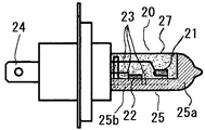
図1は本発明の自動車前照灯用ハロゲンランプは、好ましい実施の形態の一例を示すものであり、円筒状のバルブ20の軸方向の前部にタングステンからなるすれ違い用のロービーム用フィラメント21を、また軸方向の後部に走行用のハイビーム用フィラメント22を有し、それぞれのフィラメントの両端はモリブデンからなるリード線23に接続されており、リード線23はバルブシール部内のモリブデン箔を介してモリブデンピン(図示せず)に接続されている。さらに前記モリブデンピンは口金を介して給電端子24に接続される。
FIG. 1 shows an example of a preferred embodiment of a halogen lamp for an automobile headlamp according to the present invention. A low-
ロービーム用フィラメント21下部のバルブ20内にはミラー(遮光手段)は存在せず、バルブ20内には、ジブロモメタン(CH2Br2)を体積比で0.03%含むクリプトンガスが大気下にて5気圧封入してあり、バルブ20の表面はコバルト微粒子、有機溶剤からなる顔料からなる着色膜を形成し、ランプの発光色が6700Kに成る様にする。
There is no mirror (light shielding means) in the
前記バルブ20の外周部の頂部にはグレア光を除去するための耐熱性の遮光膜25aが形成され、使用状態におけるバルブ20の外周部の規格に適合した対向車に対する防眩のための配光特性を得ることが可能な様に前記バルブ20の外周部の下半位置には、耐熱性のロービーム配光用の遮光膜25bを形成する。この遮光膜25(25a、25b)はセラミック耐熱塗料(例えば品川リフラクトリーズ製セラフィーコート)によって構成し、膜厚は0.5mmを上回ると、塗料の泡ふき、剥離がしやすくなるため、0.5mm以下が望ましい。尚、前記遮光膜25の厚みは前記バルブ20の全体の温度差が極力小さくなるように選択すると良い。
A heat-resistant light-shielding
実施例2では図2に示す様に、実施例1と同様の構造における遮光膜25に代えて、前記バルブ20の外側に、当該バルブ20と適当な間隔をおいて遮光板26を配置したものである。遮光板26はグレア光を除去するためのバルブ20の頂部を覆うキャップ部分26aと使用状態における規格に適合した対向車に対する防眩のための配光特性を得ることが可能な様にバルブ20の外周部の下半位置を覆う、ロービーム配光用の半円筒部分26bが配置される。この構造では、前記遮光板26bをバルブ20に接触させてしまうと、前記遮光板26bの蓄熱作用によりバルブ20の下半位置が上部より高温になってしまうため、前記遮光板26bはバルブ20と適当な間隔をおいて配置する。実験により前記間隔Sは2mm以上、7mm以下が適当であることを確認した。(遮光板が7mmを超えると、カットラインがぼやける傾向があり望ましくない。)
In the second embodiment, as shown in FIG. 2, in place of the
以上のような構造のハロゲンランプを電源電圧13.2Vで点灯したところ、表1に示すような結果が得られた。 When the halogen lamp having the above structure was lit at a power supply voltage of 13.2 V, the results shown in Table 1 were obtained.
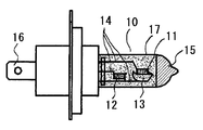
尚、前記実施例1、前記実施例2との比較用として、図3に示すようなハロゲンランプ、すなわち、円筒状のバルブ10の軸方向の前部にタングステンからなるすれ違い用のロービーム用フィラメント11を、また軸方向の後部に走行用のハイビーム用フィラメント12を有し、ハイビーム用フィラメント11はモリブデンからなるリード線14に両端を接続されており、ロービーム用フィラメント11はモリブデンからなるリード線14に一端を接続されており、他端はミラー13(遮光体)を介してリード線14に接続される。
For comparison with Example 1 and Example 2, a halogen lamp as shown in FIG. 3, that is, a
リード線14はバルブシール部内のモリブデン箔を介してモリブデンピン(図示せず)に接続されている。さらに前記モリブデンピンは口金を介して給電端子16に接続される。
The
バルブ20内には、CH2Br2を体積比で0.03%含むクリプトンガスが大気下にて5気圧封入してあり、バルブ20の表面は実施例1、実施例2と同様にコバルト微粒子、有機溶剤からなる顔料からなる着色膜を形成し、ランプの発光色が6700Kに成る様にする。
In the
前記バルブ20の外周部の頂部にはグレア光を除去するための耐熱性の遮光膜15が形成され、前記バルブ10の内部に配置されるミラー13は、使用状態において、規格に適合した対向車に対する防眩のための配光特性を得ることが可能な様に、ロービームフィラメント11の下方位置に配置される。
A heat-resistant light-shielding
ここで、前記二つの本発明の実施例と、前記従来例において、保安基準第32条に記載されている光度規格を確認すべく、光度の測定のほか、色温度、グレアの有無、についての比較測定を行った結果は以下の表1に示すとおりであった。

これより本発明の自動車前照灯用ハロゲンランプは発光色が6700Kにおいてもロービームフィラメントによる光度が保安規格である64hcd以上を有し、実用上問題のない光度が得られることがわかる。 From this, it can be seen that the halogen lamp for automotive headlamps of the present invention has a luminous intensity of 64 hcd or more, which is a safety standard, even when the emission color is 6700K, and a luminous intensity with no practical problem can be obtained.
尚、ランプバルブの下半部を覆うシェードは、ランプ表面から2mm未満であると、耐熱性が高いインコネル等の金属を用いてもシェード表面に酸化が生じ、変色、発煙が生じる場合があるので2mm以上が好ましい。またデザイン上、シェードにくり抜き加工をする際は少なくともロービームフィラメント下半部は遮光しなくてはならない。またシェード外径は25mm以下としないと、車両によっては灯具付帯のシェードと干渉してしまうので25mm以下が好ましい。 If the shade covering the lower half of the lamp bulb is less than 2 mm from the lamp surface, even if a metal such as Inconel with high heat resistance is used, oxidation may occur on the shade surface, which may cause discoloration and smoke generation. 2 mm or more is preferable. Also, by design, when cutting out the shade, at least the lower half of the low beam filament must be shielded from light. If the outer diameter of the shade is not less than 25 mm, it may interfere with the shade attached to the lamp depending on the vehicle.
純正ハロゲンランプ(3000Kの黄色味を帯びた光)と3500K、4000K、4500K、5000K、5500K、6000K、6700Kの色温度の発光色を有するハロゲンランプを車両に付けて夜間の視認性を確認したところ、4500K以上の発光色のランプが、道路白線の識別がしやすく、明るく感じることがわかった。 Visibility at night was confirmed by attaching a genuine halogen lamp (3000K yellowish light) and a halogen lamp with emission colors of 3500K, 4000K, 4500K, 5000K, 5500K, 6000K, and 6700K to the vehicle. It was found that a light emitting color lamp of 4500K or more is easy to distinguish a road white line and feels bright.
これより、色温度を高めることは、ファッション性向上のみではなく、視認性向上にも関与していることがわかった。視認性については、光量のみならず、発光色、輝度等も関与していることは、光源を利用する産業各分野で既知であり、自動車用ハロゲンランプにおいては前記実験のとおり、4500K〜6700Kのものが適しており、本発明における発光色は日本工業規格JIS−D5500の白色範囲内であり、色温度が4500Kから6700Kの発光が得られるようにバルブの光透過部外面全体に着色膜を形成することが望ましく、既存の従来技術を利用してバルブ表面の着色膜の外側面に多層干渉膜やその他の被膜や保護膜を設けても良い。 From this, it was found that increasing the color temperature is involved not only in improving fashionability but also in improving visibility. Regarding visibility, it is known in various industrial fields using light sources that not only the amount of light but also the emission color, brightness, etc., and in the halogen lamps for automobiles, as described above, 4500K to 6700K. The light emission color in the present invention is within the white range of Japanese Industrial Standard JIS-D5500, and a colored film is formed on the entire outer surface of the light transmitting portion of the bulb so that light emission of a color temperature of 4500K to 6700K can be obtained. It is desirable that a multilayer interference film or other coating film or protective film may be provided on the outer surface of the colored film on the valve surface using existing conventional technology.
本発明は視認性、ファッション性に優れた高色温度発光を有し、コストも安価なH4タイプの自動車前照灯用のランプとして産業上広く利用が可能である。 INDUSTRIAL APPLICABILITY The present invention can be widely used industrially as a lamp for an H4 type automobile headlamp that has high color temperature light emission excellent in visibility and fashionability and is inexpensive.
10:バルブ、11:ロービーム用フィラメント、12:ハイビーム用フィラメント、13:ミラー、14:リード線、15:遮光膜、16:給電端子、17:着色膜、20:バルブ、21:ロービーム用フィラメント、22:ハイビーム用フィラメント、23:リード線、24:給電端子、25:遮光膜、25a:遮光膜(グレア光除去用)、25b:遮光膜(ロービーム配光用)、26:遮光板、26a:遮光板(グレア光除去用)、26b:遮光板(ロービーム配光用)、27:着色膜、30:バルブ、31:ロービーム用フィラメント、32:ハイビーム用フィラメント、33:ミラー、34:リード線、35:遮光膜、37:着色膜、38:多層干渉膜、40:バルブ、41:ロービーム用フィラメント、42:ハイビーム用フィラメント、43:リード線、46:可視光反射膜、47:多層干渉膜、50:バルブ、51:ロービーム用フィラメント、52:ハイビーム用フィラメント、53:リード線、54:給電端子、56:可視光反射膜、57:赤外線反射膜 10: bulb, 11: filament for low beam, 12: filament for high beam, 13: mirror, 14: lead wire, 15: light shielding film, 16: feeding terminal, 17: colored film, 20: bulb, 21: filament for low beam, 22: High beam filament, 23: Lead wire, 24: Power supply terminal, 25: Light shielding film, 25a: Light shielding film (for removing glare light), 25b: Light shielding film (for low beam light distribution), 26: Light shielding plate, 26a: Light shielding plate (for removing glare light), 26b: Light shielding plate (for low beam distribution), 27: Colored film, 30: Bulb, 31: Low beam filament, 32: High beam filament, 33: Mirror, 34: Lead wire, 35: light shielding film, 37: colored film, 38: multilayer interference film, 40: bulb, 41: low beam filament, 42: high beam film 43: lead wire, 46: visible light reflecting film, 47: multilayer interference film, 50: bulb, 51: filament for low beam, 52: filament for high beam, 53: lead wire, 54: feeding terminal, 56: visible light Reflective film, 57: Infrared reflective film
Claims (6)
Priority Applications (1)
| Application Number | Priority Date | Filing Date | Title |
|---|---|---|---|
| JP2013218930A JP2014103106A (en) | 2012-10-23 | 2013-10-22 | Halogen lamp for automobile headlight |
Applications Claiming Priority (3)
| Application Number | Priority Date | Filing Date | Title |
|---|---|---|---|
| JP2012233341 | 2012-10-23 | ||
| JP2012233341 | 2012-10-23 | ||
| JP2013218930A JP2014103106A (en) | 2012-10-23 | 2013-10-22 | Halogen lamp for automobile headlight |
Publications (1)
| Publication Number | Publication Date |
|---|---|
| JP2014103106A true JP2014103106A (en) | 2014-06-05 |
Family
ID=51025412
Family Applications (1)
| Application Number | Title | Priority Date | Filing Date |
|---|---|---|---|
| JP2013218930A Pending JP2014103106A (en) | 2012-10-23 | 2013-10-22 | Halogen lamp for automobile headlight |
Country Status (1)
| Country | Link |
|---|---|
| JP (1) | JP2014103106A (en) |
Cited By (1)
| Publication number | Priority date | Publication date | Assignee | Title |
|---|---|---|---|---|
| KR102459264B1 (en) * | 2022-06-10 | 2022-10-25 | 안승종 | Halogen Lamp for Headlight of Vehicle and Method for Manufacturing the Same |
Citations (4)
| Publication number | Priority date | Publication date | Assignee | Title |
|---|---|---|---|---|
| JPH0696745A (en) * | 1992-09-14 | 1994-04-08 | Giken Kagaku Kk | Tungsten halogen lamp and manufacture thereof |
| JPH11176390A (en) * | 1997-12-11 | 1999-07-02 | Giken Kagaku Kk | Halogen lamp |
| JP2000294027A (en) * | 1999-04-06 | 2000-10-20 | Stanley Electric Co Ltd | Electric bulb for car and lighting fixture using it as light source |
| JP2002304905A (en) * | 2001-04-04 | 2002-10-18 | Ichikoh Ind Ltd | Lighting fixture for vehicle |
-
2013
- 2013-10-22 JP JP2013218930A patent/JP2014103106A/en active Pending
Patent Citations (4)
| Publication number | Priority date | Publication date | Assignee | Title |
|---|---|---|---|---|
| JPH0696745A (en) * | 1992-09-14 | 1994-04-08 | Giken Kagaku Kk | Tungsten halogen lamp and manufacture thereof |
| JPH11176390A (en) * | 1997-12-11 | 1999-07-02 | Giken Kagaku Kk | Halogen lamp |
| JP2000294027A (en) * | 1999-04-06 | 2000-10-20 | Stanley Electric Co Ltd | Electric bulb for car and lighting fixture using it as light source |
| JP2002304905A (en) * | 2001-04-04 | 2002-10-18 | Ichikoh Ind Ltd | Lighting fixture for vehicle |
Cited By (1)
| Publication number | Priority date | Publication date | Assignee | Title |
|---|---|---|---|---|
| KR102459264B1 (en) * | 2022-06-10 | 2022-10-25 | 안승종 | Halogen Lamp for Headlight of Vehicle and Method for Manufacturing the Same |
Similar Documents
| Publication | Publication Date | Title |
|---|---|---|
| CN201448753U (en) | Vehicle halogen lamp with metal lens hood | |
| EP3014649B1 (en) | Lamp and headlighting arrangement for obtaining a color appearance in an automotive headlight | |
| EP1228525B1 (en) | Halogen incandescent lamp for motor vehicles | |
| HUE033106T2 (en) | Lamp with a lamp vessel coated in places | |
| JP2014103106A (en) | Halogen lamp for automobile headlight | |
| EP2359385B1 (en) | Lamp | |
| JP2006517328A (en) | Lamp and lighting unit with shading mechanism and interference coating for improving color temperature uniformity | |
| CN107110455B (en) | Lamp with heat shielding element | |
| CA2622199A1 (en) | Reflector lamp | |
| EP1576645B1 (en) | High-pressure discharge lamp | |
| JPH0290454A (en) | Head light lantern system and lamp suitable for use in this system | |
| JPS6118303B2 (en) | ||
| US20090039786A1 (en) | Compact incandescent lamp with integrated reflector | |
| EP2605268A2 (en) | Anisotropic indandescent light source | |
| JP2006515103A (en) | High pressure discharge lamp | |
| JP3103397U (en) | Automotive lighting | |
| KR200314690Y1 (en) | carbon heat radiation lamp | |
| EP2997593A1 (en) | Double-filament incandescent lamp for automotive vehicle front lighting | |
| JP2001160377A (en) | Tungsten halogen lamp, headlight for automobiles, and illuminator | |
| JP2005216630A (en) | Lamp with reflector | |
| JPH03252045A (en) | Incandescent lamp for vehicle | |
| JPH08102306A (en) | Electric bulb, electric bulb for vehicle headlamp, vehicle headlamp, and vehicle | |
| JPH07288114A (en) | Incandiscent electric bulb and illumination device using it | |
| JP2012119227A (en) | Vehicular headlamp | |
| JPH0492357A (en) | Tube-form incandescent lamp |
Legal Events
| Date | Code | Title | Description |
|---|---|---|---|
| A621 | Written request for application examination |
Free format text: JAPANESE INTERMEDIATE CODE: A621 Effective date: 20160809 |
|
| A977 | Report on retrieval |
Free format text: JAPANESE INTERMEDIATE CODE: A971007 Effective date: 20170516 |
|
| A131 | Notification of reasons for refusal |
Free format text: JAPANESE INTERMEDIATE CODE: A131 Effective date: 20170524 |
|
| A02 | Decision of refusal |
Free format text: JAPANESE INTERMEDIATE CODE: A02 Effective date: 20171114 |