JP2014102776A - Signal controller - Google Patents
Signal controller Download PDFInfo
- Publication number
- JP2014102776A JP2014102776A JP2012255951A JP2012255951A JP2014102776A JP 2014102776 A JP2014102776 A JP 2014102776A JP 2012255951 A JP2012255951 A JP 2012255951A JP 2012255951 A JP2012255951 A JP 2012255951A JP 2014102776 A JP2014102776 A JP 2014102776A
- Authority
- JP
- Japan
- Prior art keywords
- signal
- dimming control
- dimming
- control
- vehicle
- Prior art date
- Legal status (The legal status is an assumption and is not a legal conclusion. Google has not performed a legal analysis and makes no representation as to the accuracy of the status listed.)
- Granted
Links
Images


Abstract
Description
本発明は、主道路と従道路とが交差する交差点の信号灯器を制御する信号制御機に関する。 The present invention relates to a signal controller for controlling a signal lamp at an intersection where a main road and a secondary road intersect.
近年、交通信号灯器は、電球式から、電球式に比較して低消費電力且つ長寿命のLED式に置き換えられている。このLED式の交通信号灯器では、各灯色のLEDへの供給電力をPWM制御によって可変することで輝度を調整する調光が可能である(例えば、特許文献1参照)。 In recent years, traffic signal lamps have been replaced from light bulb types by LED types with lower power consumption and longer life compared to light bulb types. In this LED type traffic signal lamp, dimming that adjusts the luminance by changing the power supplied to the LED of each lamp color by PWM control is possible (for example, see Patent Document 1).
ところで、交通信号灯器は1つの交差点に複数設置されており、全国規模で考えた場合は勿論のこと、市区町村単位で考えた場合でも、設置される交通信号灯器の総数は多大である。また、点滅状態を除き、交通信号灯器は終日、赤灯、黄灯、青灯の何れかが必ず点灯しており、全てが消灯することはない。つまり、これらの信号灯器の点灯に要する消費電力の総量は莫大なものとなる。特に近年では、交通信号灯器の点灯に要する消費電力の更なる削減が求められており、例えば上述の調光は消費電力の削減に有効であると考えられる。 By the way, a plurality of traffic signal lamps are installed at one intersection, and the total number of traffic signal lamps to be installed is great even when considered on a municipal basis as well as on a nationwide scale. Also, except for the blinking state, the traffic signal lamps are always turned on in red light, yellow light, and blue light throughout the day, and all are not turned off. That is, the total amount of power consumed for lighting these signal lamps is enormous. Particularly in recent years, there has been a demand for further reduction in power consumption required for lighting traffic signal lamps. For example, the above-described dimming is considered to be effective in reducing power consumption.
本発明は、上記事情に鑑みてなされたものであり、その目的とするところは、信号灯器の点灯に要する消費電力の新たな削減技術の実現にある。特に、従道路の信号灯器に係る消費電力の削減を図る技術に関する。 The present invention has been made in view of the above circumstances, and an object thereof is to realize a new technology for reducing power consumption required for lighting a signal lamp. In particular, the present invention relates to a technique for reducing power consumption related to a signal lamp on a secondary road.
上記課題を解決するための第1の発明は、
従道路に車両感知器が設置された主道路と従道路とが交差する交差点の信号灯器を制御する信号制御機(例えば、図1の交通信号制御機50)であって、
調光制御を実行する時間帯であるか否かを判定する時間帯判定手段(例えば、図3の調光実行判定部120)と、
前記時間帯判定手段により肯定判定された場合に、前記車両感知器の感知結果を用いて前記従道路用の信号灯器の調光制御を実行する調光制御手段(例えば、図3の調光制御部130)と、
を備えた信号制御機である。
The first invention for solving the above-described problems is
A signal controller (for example,
Time zone determination means for determining whether or not it is a time zone for executing dimming control (for example, the dimming
A dimming control unit (for example, the dimming control of FIG. 3) that executes dimming control of the signal lamp for the secondary road using the detection result of the vehicle sensor when the time zone determination unit makes a positive determination. Part 130),
It is a signal controller provided with.
この第1の発明によれば、主道路と従道路とが交差する交差点の信号灯器を制御する信号制御機であって、調光制御を実行する時間帯である場合に、従道路に設置された車両感知器の感知結果を用いて従道路用の信号灯器の調光制御を実行する信号制御機が実現される。これにより、例えば夜間といった交通量が少ない時間帯において、実際に従道路が車両無しの場合には従道路用の信号灯器を減光する調光制御を行うといったことが可能になる。これにより、通常点灯を行う必要がない時の従道路要の信号灯器の点灯に要する消費電力を削減できる。 According to the first aspect of the present invention, the signal control device controls the signal lamp at the intersection where the main road and the secondary road intersect, and is installed on the secondary road when it is a time zone in which dimming control is executed. A signal controller that performs dimming control of the signal lamp for the secondary road using the detection result of the vehicle sensor is realized. This makes it possible to perform dimming control for dimming the signal lamp for the secondary road when the secondary road is actually without a vehicle in a time zone where the traffic volume is low, such as at night. As a result, it is possible to reduce the power consumption required for lighting the signal lamp on the secondary road when it is not necessary to perform normal lighting.
また、第2の発明として、第1の発明の信号制御機であって、
前記調光制御手段は、前記調光制御として、前記従道路用の信号灯器の赤灯を減光するか否かの制御を実行する赤灯減光制御手段(例えば、図3の調光制御部130)を有する、
信号制御機を構成しても良い。
As a second invention, the signal controller of the first invention,
The dimming control means is a red light dimming control means (for example, dimming control in FIG. 3) for performing control as to whether or not the red light of the signal lamp for the secondary road is dimmed as the dimming control. Part 130),
A signal controller may be configured.
この第2の発明によれば、調光制御として、従道路用の信号灯器の赤灯の減光制御が実行される。 According to the second aspect of the invention, the dimming control of the red lamp of the signal lamp for the secondary road is executed as the dimming control.
また、第3の発明として、第2の発明の信号制御機であって、
前記車両感知器の感知結果に基づく半感応式制御を行う半感応式制御手段(例えば、図3の信号制御部110)を更に備え、
前記調光制御手段は、前記半感応式制御手段による前記半感応式制御が実行中であり、且つ、前記時間帯判定手段により肯定判定された場合に、前記赤灯減光制御手段による制御を実行する、
信号制御機を構成しても良い。
Further, as a third invention, the signal controller of the second invention,
Semi-sensitive control means (for example, the
The dimming control means performs control by the red light dimming control means when the semi-sensitive control by the semi-sensitive control means is being executed and an affirmative determination is made by the time zone determination means. Run,
A signal controller may be configured.
この第3の発明によれば、車両感知器の感知結果に基づく半感応式制御が実行中であり、且つ、調光制御を実行する時間帯である場合に、従道路用の信号灯器の赤灯の減光制御が実行される。半感応式制御は、通常は交通量が多い主道路に通行権を与え、車両感知器によって従道路の交通が感知されると従道路に通行権を与える制御方式である。従って、半感応式制御を実行中に、車両無しとなっている従道路用の信号灯器の赤灯を減光制御することで、交通に対して信号現示を表示するといった本来の目的を損なうことなく、交差点全体の信号灯器の消費電力の低減を図ることができる。 According to the third aspect of the present invention, when the semi-sensitive control based on the detection result of the vehicle detector is being executed and the time period during which the dimming control is executed, Light dimming control is executed. The semi-sensitive control is a control method in which a right of passage is usually given to the main road having a large traffic volume, and the right of passage is given to the subway when the traffic on the subway is detected by the vehicle detector. Therefore, during the execution of the semi-sensitive control, the original purpose of displaying the signal indication for the traffic is lost by controlling the red light of the signal lamp for the secondary road where there is no vehicle. Therefore, it is possible to reduce the power consumption of the signal lamp at the entire intersection.
また、第4の発明として、第3の発明の信号制御機であって、
前記赤灯減光制御手段は、前記車両感知器による感知無しの継続時間条件を満たした時に前記赤灯を減光させ、減光制御を開始した後に前記車両感知器による感知が有った時に減光制御を中止する、
信号制御機を構成しても良い。
Moreover, as 4th invention, it is the signal controller of 3rd invention,
The red light dimming control means dims the red light when the duration time without sensing by the vehicle sensor is satisfied, and when there is sensing by the vehicle sensor after starting the dimming control Stop dimming control,
A signal controller may be configured.
この第4の発明によれば、従道路用の信号灯器の赤灯は、車両感知器による感知無しの継続時間条件を満たした時に減光され、減光制御を開始した後に車両感知器による感知が有った時に減光制御が中止される。つまり、従道路の車両無しが所定時間継続された後に、従道路の信号灯器の赤灯が減光され、この減光は従道路の車両有りとなった時点で解除される。従道路を走行する車両の運転手にとっては、当初減光されていた赤灯を視認して運転していたが、車両感知器の感知によって減光が解除されて通常点灯に戻るため、あたかも増光されたかのような印象を受ける。このため、従道路を走行する車両の運転手に対して、停止を強く意識させるという副次的な効果を発揮し得る。 According to the fourth aspect of the present invention, the red light of the signal lamp for the secondary road is dimmed when the duration condition without sensing by the vehicle sensor is satisfied, and is sensed by the vehicle sensor after starting the dimming control. Dimming control is stopped when there is That is, after the absence of a vehicle on the secondary road continues for a predetermined time, the red light of the signal lamp on the secondary road is dimmed, and this dimming is canceled when the vehicle on the secondary road is present. The driver of the vehicle traveling on the secondary road was driving by visually recognizing the red light that was initially dimmed. However, the dimming is canceled by the detection of the vehicle detector and returns to normal lighting. I get the impression that it was done. For this reason, the secondary effect of making the driver of the vehicle traveling on the secondary road strongly aware of the stop can be exhibited.
また、第5の発明として、第1の発明の信号制御機であって、
前記調光制御手段は、前記車両感知器の感知結果に基づく交通量が閑散状態を示す条件を満たした時に前記従道路用の信号灯器を減光させ、減光制御を開始した後に当該条件を満たさなくなった時に減光制御を中止する、
信号制御機を構成しても良い。
Further, as a fifth invention, the signal controller of the first invention,
The dimming control means dimmes the signal lamp for the secondary road when the traffic volume based on the detection result of the vehicle detector satisfies a condition indicating a quiet state, and after the dimming control is started, Stop dimming control when it is no longer satisfied,
A signal controller may be configured.
この第5の発明によれば、従道路用の信号灯器の調光制御として、車両感知器の感知結果に基づく交通量が閑散状態を示す条件を満たした時に、従道路用の信号灯器を減光させ、減光制御を開始した後に当該条件を満たさなくなった時に減光制御が中止される。これにより、例えば従道路の交通量が少ない場合に、従道路用の信号灯器を減光させるといったことができ、信号灯器の点灯に要する消費電力の削減を図ることができる。また、従道路を走行する車両の運転手にとっては、当初減光されていた赤灯を視認して運転していたが、車両感知器の感知によって減光が解除されて通常点灯に戻るため、あたかも増光されたかのような印象を受ける。このため、従道路を走行する車両が、他の車両が停止していない当該交差点に差し掛かったときに、当該車両の運転手に対して、停止を強く意識させるという副次的な効果を発揮し得る。 According to the fifth aspect of the present invention, as the dimming control of the signal lamp for the secondary road, the signal lamp for the secondary road is reduced when the traffic volume based on the detection result of the vehicle sensor satisfies the condition indicating a quiet state. The dimming control is stopped when the condition is not satisfied after the light is turned on and the dimming control is started. Accordingly, for example, when the traffic volume on the secondary road is small, the signal lamp for the secondary road can be dimmed, and the power consumption required for lighting the signal lamp can be reduced. In addition, for the driver of the vehicle traveling on the secondary road, it was driving by visually recognizing the red light that was initially dimmed, but because the dimming is canceled by the detection of the vehicle detector, it returns to normal lighting, The impression is as if it was brightened. For this reason, when a vehicle traveling on a secondary road reaches the intersection where other vehicles are not stopped, a secondary effect of making the driver of the vehicle strongly aware of the stop is exhibited. obtain.
以下、図面を参照して本発明の実施形態を説明する。本発明の適用可能な実施形態がこれに限定されるものではない。 Hereinafter, embodiments of the present invention will be described with reference to the drawings. The applicable embodiment of the present invention is not limited to this.
[全体]
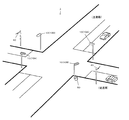
図1は、本実施形態の交通信号制御システム1の設置例である。交通信号制御システム1は、自交差点で独立して交通信号を制御する地点制御方式であり、信号灯器10と、車両感知器40と、交通信号制御機50とを備えて構成される。各信号灯器10及び各車両感知器40と交通信号制御機50との間は、有線通信或いは無線通信によってデータ通信が可能に接続されている。
[The entire]
FIG. 1 is an installation example of the traffic
また、この交通信号制御システム1が設置される交差点は、主道路と従道路とが交差する十字交差点である。そして、信号灯器10として、主道路の車両交通を対象とする主道路用信号灯器10Aと、従道路の車両交通を制御対象とする従道路用信号灯器10Bとが設置されている。また、従道路の車両交通を感知対象とする車両感知器40が設置されている。なお、図1の交差点では、簡単のため、歩行者用の横断歩道及び信号装置は設置されていないとしている。
The intersection where the traffic
信号灯器10は、交差点へ進入する車両交通を制御対象とする車両用であり、制御対象の交通車両に対面するよう、交差点の所定位置に設置された柱の上方に取り付けられている。
The
車両感知器40は、従道路から交差点へ進入する車両交通を感知対象とし、路側に設置された柱の上方に、感知対象の走行レーンを上方から俯瞰するように設置されている。車両感知器40による感知信号は、随時、交通信号制御機50に出力される。車両感知器40は超音波式や光学式等の公知の感知器を利用することができる。
The
交通信号制御機50は、例えば、何れかの信号灯器10が取り付けられた柱の下方やその近傍に設置され、自交差点の交通信号全体を制御する。具体的には、信号制御方式として、定周期制御或いは半感応制御(リコール制御)を、時間帯によって切り替えて実施する。特に、本実施形態では、半感応制御において、従道路に車両無しの状態が所定時間継続された場合に、従道路用信号灯器10Bの赤灯を減光させる。この減光は、車両感知器40によって従道路の車両が感知されると解除される。
The
図2は、半感応制御における赤灯の減光タイミングを説明するタイムチャートである。図2の(1)は半感応制御下におけるバックグラウンドの信号制御のタイムチャートであり、主道路の現示と、従道路の現示とを示している。バックグラウンドの信号制御では、主道路と従道路に交互に通行権を与えるように現示が構成されている。 FIG. 2 is a time chart for explaining the dimming timing of the red light in the semi-sensitive control. (1) in FIG. 2 is a time chart of background signal control under semi-sensitive control, and shows a main road and a secondary road. In the background signal control, the display is configured so that the right of passage is alternately given to the main road and the secondary road.
図2の(2)は、半感応制御下における実際の信号制御のタイムチャートの一例であり、車両感知器40による従道路の感知結果と、主道路の現示と、従道路の現示とを示している。半感応制御では、従道路が感知無しの場合、バックグラウンドの制御に関わらず、主道路は青現示(1G)、従道路は赤現示(2R)となる。そして、従道路の感知無しの状態のまま、従道路が赤現示となった時刻t1からの継続時間が規定時間Taに達した時刻t2において(継続時条件を満たす)、従道路用信号灯器10Bの赤灯の減光が開始される。
(2) of FIG. 2 is an example of a time chart of actual signal control under the semi-sensitive control. The detection result of the secondary road by the
この従道路用信号灯器10Bの赤灯の減光は、その後、従道路が感知有りとなった時刻t3において解除される。そして、感知直後のサイクルは、バックグランドで進行しているステップに合わせて信号現示を変化させる(半感応制御)。すなわち、主道路を青現示(1G)から黄現示(1Y)、赤現示(1R)そして青現示(1G)に変化させる階梯に合わせて、従道路を赤現示(2R)から青現示(2G)、黄現示(2Y)そして赤現示(2R)へと変化させる。
The dimming of the red light of the slave
ここで、従道路用信号灯器Bの赤灯の減光を開始するための規定時間Taは、任意に設定可能であるが、例えば、バックグラウンドにおける主道路の青現示(1G)の階梯に定められた時間Tg以上とすることが望ましい。勿論、時間Ta=時間Tgとしてもよい。 Here, the prescribed time Ta for starting the dimming of the red light of the secondary road signal lamp B can be arbitrarily set. For example, on the floor of the blue display (1G) of the main road in the background. It is desirable to set the time Tg or more. Of course, time Ta = time Tg may be set.
[交通信号制御システムの構成]
図3は、交通信号制御システム1の構成図である。図3によれば、交通信号制御機50は、機能的には、灯器駆動部20と、操作部52と、計時部54と、処理部100と、記憶部200とを備える。
[Configuration of traffic signal control system]
FIG. 3 is a configuration diagram of the traffic
灯器駆動部20は、信号灯器10それぞれに対応して設けられ、主道路用信号灯器10Aを駆動対象とする主道路用灯器駆動部20Aと、従道路用信号灯器10Bを駆動対象とする従道路用灯器駆動部20Bとがある。
The
灯器駆動部20は、電源部22と、リレー部24とを有する。電源部22は、商用電源を用いて信号灯器10の各灯器に供給する直流電力を生成する。具体的には、通常は、商用電源(交流100V)を全波整流することで直流電力を生成する。また、調光制御部130から減光指令が入力された場合には、商用電源を半波整流して直流電力に変換することで、信号灯器10への供給電力(電流)を減少させる。そして、減光解除指令が入力されると、半波整流から全波整流に変更する。減光制御の方式はこの方式に限らず、PWM方式とし、パルス幅を変更することで減光及び省電力を実現することとしてもよい。
The
リレー部24は、信号灯器10が有する3つの灯器(赤灯12、黄灯14及び青灯16)それぞれに対応して設けられ、信号制御部110からの点灯/滅灯指令に従って、電源部22から対応する灯色に供給される直流電力をオン/オフする。
The
信号灯器10は、LED素子からなる赤灯12、黄灯14及び青灯16の3つの灯器を有する。
The
操作部52は、例えばボタンスイッチやタッチパネル等の入力装置で実現され、交通信号制御システム1の管理者の操作に応じた操作信号を処理部100に出力する。計時部54は、現在時刻や、指定タイミングからの経過時間を計時し、計時した現在時刻や経過時間を処理部100に出力する。
The
処理部100は、例えばCPU等の演算装置で実現され、記憶部200に記憶されたプログラムやデータ、車両感知器40からの感知信号等に基づいて、交通信号制御機50を構成する各部への指示やデータ転送を行い、交通信号制御機50の全体制御を行う。また、処理部100は、信号制御部110と、調光実行判定部120と、調光制御部130と、車両有無判定部140とを有し、信号制御プログラム210に従った信号制御処理(図7参照)を行う。
The
信号制御部110は、信号灯器10の点灯/滅灯を制御する。このとき、信号制御方式設定テーブル230を参照し、現在時刻に応じて定周期制御及び半感応制御の何れかの信号制御方式を用いる。
The
図4は、信号制御方式設定テーブル230のデータ構成の一例を示す図である。図4によれば、信号制御方式設定テーブル230は、1日を区切った時間帯と、信号制御方式の種類とを対応付けて格納している。 FIG. 4 is a diagram illustrating an example of a data configuration of the signal control method setting table 230. According to FIG. 4, the signal control method setting table 230 stores a time zone dividing one day and the type of signal control method in association with each other.
調光実行判定部120は、調光制御を実行するか否かを判定する。具体的には、現在時刻が調光制御設定テーブル240において調光制御を実行するとして定められている時間帯であり、且つ、信号制御部110によってなされている現在の信号制御方式が半感応制御である場合に、調光制御を実行すると判定する。
The dimming
図5は、調光制御設定テーブル240のデータ構成の一例を示す図である。図5によれば、調光制御設定テーブル240は、1日を区切った時間帯に、調光制御の実行有無を対応付けて格納している。本実施形態では、半感応制御が実行される時間帯と調光制御を行う時間帯とが一致するとして定めているが、双方の時間帯が一致していなくとも良い。 FIG. 5 is a diagram illustrating an example of a data configuration of the dimming control setting table 240. According to FIG. 5, the dimming control setting table 240 stores the execution / non-execution of dimming control in association with the time period divided by one day. In the present embodiment, it is determined that the time zone in which the semi-sensitive control is executed and the time zone in which the dimming control is performed match, but both time zones do not have to match.
調光制御部130は、調光実行判定部120によって調光制御を実行すると判定されている場合に、従道路用信号灯器10Bの調光制御を行う。具体的には、信号制御部110によって従道路用信号灯器10Bが赤現示に制御されており、且つ、車両感知器40によって従道路の車両無しが感知されている状態の継続時間が所定の継続時間条件を満たす場合に、従道路用灯器駆動部20Bの電源部22に減光指令を出力して従道路用信号灯器10Bの赤灯12を減光させる(図2参照)。
The dimming
そして、従道路用信号灯器10Bの赤灯12を減光させた後は、車両有無判定部140によって従道路の車両有りと判定された時点で、従道路用灯器駆動部20Bの電源部22に減光解除指令を出力して従道路用信号灯器10Bの赤灯12の減光を解除させる。
Then, after the
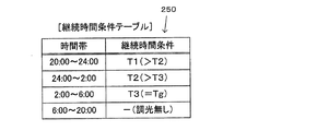
ここで、継続時間条件は、継続時間条件テーブル250に設定されている。調光制御部130は、現在時刻を含む時間帯に対応する継続時間条件を採用する。図6は、継続時間条件テーブル250のデータ構成の一例を示す図である。図6によれば、継続時間条件テーブル250は、1日を区切った時間帯それぞれに、継続時間条件を対応付けて格納している。図6に示す例では、交通量が最も少ないと想定される深夜〜早朝の時間帯の継続時間条件T3が、主導路の青現示(1G)の階梯に定められた時間Tgと同じ長さに設定され、当該時間帯から離れる時間帯ほど(より早い時間帯ほど)、徐々に長い時間になるように継続時間条件が設定されている。
Here, the duration condition is set in the duration condition table 250. The dimming
車両有無判定部140は、車両感知器40の感知信号をもとに、従道路から交差点へ進入しようとする車両の有無を検知する。
The vehicle presence /
記憶部200は、ROMやRAM、ハードディスク等の記憶装置で実現され、処理部100が交通信号制御機50を統合的に制御するためのシステムプログラムや、各種機能を実現するためのプログラムやデータ等を記憶しているとともに、処理部100の作業領域として用いられ、処理部100が各種プログラムに従って実行した演算結果が一時的に格納される。本実施形態では、記憶部200には、信号制御プログラム210と、信号制御パラメータ220と、信号制御方式設定テーブル230と、調光制御設定テーブル240と、継続時間条件テーブル250とが記憶される。
The
[処理の流れ]
図7は、信号制御処理を説明するフローチャートである。なお、図7では、本実施形態の特徴である信号灯器10の調光に関する処理のみを示している。
[Process flow]
FIG. 7 is a flowchart illustrating the signal control process. In FIG. 7, only processing related to light control of the
先ず、信号制御部110が、現在時刻に応じて信号制御方式を決定する。すなわち、現在時刻が半感応制御の実行時間帯でないならば(ステップA1:NO)、信号制御部110は、定周期制御での信号制御を行う(ステップA3)。
First, the
一方、半感応制御の実行時間帯であるならば(ステップA1:YES)、信号制御部110は、半感応制御での信号制御を行う(ステップA5)。次いで、調光実行判定部120が、現在時刻が調光制御の実行時間帯であるか否かを判定し、調光制御の実行時間帯でないならば(ステップA7:NO)、従道路用信号灯器10Bの赤灯12を通常点灯させる。すなわち、減光されているならば、従道路用灯器駆動部20Bに減光解除指令を出力して、従道路用信号灯器10Bの赤灯の減光を解除する(ステップA9)。
On the other hand, if it is the execution time zone of the semi-sensitive control (step A1: YES), the
一方、調光制御の実行時間帯ならば(ステップA7:YES)、更に、車両有無判定部140による従道路の車両有無の判定結果を判断し、車両有りが判定されたならば(ステップA11:YES)、調光制御部130が、従道路用灯器駆動部20Bに減光解除指令を出力して、従道路用信号灯器10Bの赤灯12の減光を解除する(ステップA13)。
On the other hand, if it is the execution time zone of the dimming control (step A7: YES), the determination result of the presence / absence of the vehicle on the secondary road by the vehicle presence /
また、車両有無判定部140によって従道路の車両無しが判定されたならば(ステップA11:NO)、調光制御部130が、従道路用信号灯器10Bが赤現示である状態での車両無しの判定の継続時間が、継続時間条件を満たすか否かを判定する。その結果、継続時間条件を満たすならば(ステップA15:YES)、従道路用灯器駆動部20Bに減光指令を出力して、従道路用信号灯器10Bの赤灯12を減光させる(ステップA17)。その後、ステップA1に戻り、同様の処理を繰り返す。
If the vehicle presence /
[作用効果]
このように、本実施形態の交通信号制御システム1では、主道路と従道路とが交差する交差点において半感応制御(リコール制御)を行っている場合に、車両感知器40による従道路の車両無しが所定時間継続されると、従道路用信号灯器10Bの赤灯12を減光する。この減光は、車両感知器40によって従道路の車両有りが感知された場合に解除する。これにより、信号灯器10の点灯に要する消費電力を削減することができる。また、この減光は、交通量が少ない従道路の信号灯器10を対象として行うものであるとともに、従道路に車両無しのときに行うため、車両に対して信号現示を表示するといった信号灯器10の本来の目的を損なうことがない。また、従道路を走行する車両の運転手にとっては、当初減光されていた赤灯を視認して運転していたが、車両感知器の感知によって減光が解除されて通常点灯に戻るため、あたかも増光されたかのような印象を受ける。このため、従道路を走行する車両が、他の車両が停止していない当該交差点に差し掛かったときに、当該車両の運転手に対して、停止を強く意識させるという副次的な効果を生む。
[Function and effect]
As described above, in the traffic
[変形例]
なお、本発明の適用可能な実施形態は、上述の実施形態に限定されることなく、本発明の趣旨を逸脱しない範囲で適宜変更可能なのは勿論である。
[Modification]
It should be noted that embodiments to which the present invention can be applied are not limited to the above-described embodiments, and can be appropriately changed without departing from the spirit of the present invention.
(A)継続時間条件
例えば、上述の実施形態においては、継続時間条件は現在時刻をもとに決定することにしたが(図6の継続時間条件テーブル250)、車両感知器40による感知履歴にもとづいて決定することにしても良い。
(A) Duration condition For example, in the above-described embodiment, the duration condition is determined based on the current time (the duration condition table 250 in FIG. 6). You may decide based on it.
具体的には、直前の所定期間(複数サイクル期間)における車両有りの感知回数を計数し、この感知回数に応じて継続時間条件を決定する。例えば、交通量が閑散状態を示す閾値を定め、感知回数がこの閾値以下の場合に、継続時間条件を満たす(減光を開始する)こととする。この場合、更に次のようにしてもよい。すなわち、感知回数が少ないほど、従道路の交通量が少ないとみなせるので、感知回数が少ないほど、より短い時間を継続時間条件として設定する。 Specifically, the number of times that the vehicle is detected in the immediately preceding predetermined period (a plurality of cycle periods) is counted, and the duration condition is determined according to this number of times of detection. For example, a threshold value indicating that the traffic volume is in a quiet state is set, and the duration time condition is satisfied (the dimming is started) when the number of times of sensing is equal to or less than the threshold value. In this case, the following may be further performed. That is, the smaller the number of detections, the less the traffic on the secondary road, so the shorter the number of detections, the shorter the time is set as the duration condition.
(B)減光制御の実施
また、上述の実施形態では、半感応制御において、従道路用信号灯器10Bの赤灯の減光を実施することにしたが、定周期制御において、従道路用信号灯器10Bの減光を実施することにしても良い。
(B) Execution of dimming control In the above-described embodiment, the red light of the secondary
具体的には、車両感知器40の感知結果をもとに従道路の交通量を算出する。そして、算出した交通量が、閑散状態とみなす所定の交通量を下回る状態が所定時間以上継続された場合に、従道路用信号灯器10Bを減光する。この減光の解除は、従道路の交通量が上述の所定の交通量以上となった時点で行う。また、この減光は、赤灯12のみを対象として行っても良いし、全ての灯色を対象として行っても良い。
Specifically, the traffic volume of the follower road is calculated based on the detection result of the
(C)灯器駆動部20
また、上述の実施形態では、信号灯器10それぞれの灯器駆動部20を交通信号制御機50に内蔵する構成としたが、灯器駆動部20それぞれを、その駆動対象の信号灯器10に内蔵させたり、或いは、駆動対象の信号灯器10が設けられた柱に単体の装置として設置することにしても良い。
(C)
Further, in the above-described embodiment, the
1 交通信号制御システム
10 信号灯器、12 赤灯、14 黄灯、16 青灯
40 車両感知器
50 交通信号制御機
20 灯器駆動部、22 電源部、24 リレー部
52 操作部、54 計時部
100 処理部
110 信号制御部、120 調光実行判定部
130 調光制御部、140 車両有無判定部
200 記憶部
210 信号制御プログラム
220 信号制御パラメータ、230 信号制御方式設定テーブル
240 調光制御設定テーブル、250 継続時間条件テーブル
DESCRIPTION OF
Claims (5)
調光制御を実行する時間帯であるか否かを判定する時間帯判定手段と、
前記時間帯判定手段により肯定判定された場合に、前記車両感知器の感知結果を用いて前記従道路用の信号灯器の調光制御を実行する調光制御手段と、
を備えた信号制御機。 A signal controller for controlling a signal lamp at an intersection where a main road where a vehicle detector is installed on a secondary road and the secondary road intersect,
A time zone determining means for determining whether or not it is a time zone for executing dimming control;
A dimming control unit that executes dimming control of the signal light device for the secondary road using a detection result of the vehicle detector when an affirmative determination is made by the time zone determination unit;
A signal controller equipped with.
請求項1に記載の信号制御機。 The dimming control means has a red light dimming control means for performing control as to whether or not the red light of the signal light device for the secondary road is dimmed as the dimming control.
The signal controller according to claim 1.
前記調光制御手段は、前記半感応式制御手段による前記半感応式制御が実行中であり、且つ、前記時間帯判定手段により肯定判定された場合に、前記赤灯減光制御手段による制御を実行する、
請求項2に記載の信号制御機。 A semi-sensitive control means for performing semi-sensitive control based on a sensing result of the vehicle sensor;
The dimming control means performs control by the red light dimming control means when the semi-sensitive control by the semi-sensitive control means is being executed and an affirmative determination is made by the time zone determination means. Run,
The signal controller according to claim 2.
請求項3に記載の信号制御機。 The red light dimming control means dims the red light when the duration time without sensing by the vehicle sensor is satisfied, and when there is sensing by the vehicle sensor after starting the dimming control Stop dimming control,
The signal controller according to claim 3.
請求項1に記載の信号制御機。 The dimming control means dimmes the signal lamp for the secondary road when the traffic volume based on the detection result of the vehicle detector satisfies a condition indicating a quiet state, and after the dimming control is started, Stop dimming control when it is no longer satisfied,
The signal controller according to claim 1.
Priority Applications (1)
| Application Number | Priority Date | Filing Date | Title |
|---|---|---|---|
| JP2012255951A JP5982267B2 (en) | 2012-11-22 | 2012-11-22 | Signal controller |
Applications Claiming Priority (1)
| Application Number | Priority Date | Filing Date | Title |
|---|---|---|---|
| JP2012255951A JP5982267B2 (en) | 2012-11-22 | 2012-11-22 | Signal controller |
Publications (2)
| Publication Number | Publication Date |
|---|---|
| JP2014102776A true JP2014102776A (en) | 2014-06-05 |
| JP5982267B2 JP5982267B2 (en) | 2016-08-31 |
Family
ID=51025209
Family Applications (1)
| Application Number | Title | Priority Date | Filing Date |
|---|---|---|---|
| JP2012255951A Active JP5982267B2 (en) | 2012-11-22 | 2012-11-22 | Signal controller |
Country Status (1)
| Country | Link |
|---|---|
| JP (1) | JP5982267B2 (en) |
Cited By (4)
| Publication number | Priority date | Publication date | Assignee | Title |
|---|---|---|---|---|
| CN105575145A (en) * | 2015-12-13 | 2016-05-11 | 宜兴市华兴交通工程有限公司 | Traffic signal lamp adapting itself to haze environment |
| KR101687802B1 (en) * | 2015-06-18 | 2016-12-20 | 주식회사소노위즈 | Crossroad traffic guiding apparatus based on moving object detection using radar |
| GB2594540A (en) * | 2019-11-21 | 2021-11-03 | Agd Systems Ltd | Traffic signalling apparatus |
| KR102589218B1 (en) | 2023-07-12 | 2023-10-16 | 한국건설기술연구원 | Traffic signal indicating module and traffic signal indicating apparatus using the same |
Families Citing this family (1)
| Publication number | Priority date | Publication date | Assignee | Title |
|---|---|---|---|---|
| CN111028523A (en) * | 2019-12-16 | 2020-04-17 | 东软集团股份有限公司 | Signal lamp control method, device and equipment |
Citations (5)
| Publication number | Priority date | Publication date | Assignee | Title |
|---|---|---|---|---|
| JPH0793690A (en) * | 1993-09-27 | 1995-04-07 | Kyosan Electric Mfg Co Ltd | Traffic signal controller |
| JP2007034749A (en) * | 2005-07-27 | 2007-02-08 | Oputeima:Kk | Control system and method of traffic regulating lamp |
| JP2008003952A (en) * | 2006-06-23 | 2008-01-10 | Sumitomo Electric Ind Ltd | Traffic object detecting device |
| JP2011123595A (en) * | 2009-12-09 | 2011-06-23 | Nippon Signal Co Ltd:The | Traffic signal system |
| JP2013003976A (en) * | 2011-06-20 | 2013-01-07 | Sumitomo Electric Ind Ltd | Traffic signal control system, and central device and traffic signal control apparatus used for the system |
-
2012
- 2012-11-22 JP JP2012255951A patent/JP5982267B2/en active Active
Patent Citations (5)
| Publication number | Priority date | Publication date | Assignee | Title |
|---|---|---|---|---|
| JPH0793690A (en) * | 1993-09-27 | 1995-04-07 | Kyosan Electric Mfg Co Ltd | Traffic signal controller |
| JP2007034749A (en) * | 2005-07-27 | 2007-02-08 | Oputeima:Kk | Control system and method of traffic regulating lamp |
| JP2008003952A (en) * | 2006-06-23 | 2008-01-10 | Sumitomo Electric Ind Ltd | Traffic object detecting device |
| JP2011123595A (en) * | 2009-12-09 | 2011-06-23 | Nippon Signal Co Ltd:The | Traffic signal system |
| JP2013003976A (en) * | 2011-06-20 | 2013-01-07 | Sumitomo Electric Ind Ltd | Traffic signal control system, and central device and traffic signal control apparatus used for the system |
Cited By (5)
| Publication number | Priority date | Publication date | Assignee | Title |
|---|---|---|---|---|
| KR101687802B1 (en) * | 2015-06-18 | 2016-12-20 | 주식회사소노위즈 | Crossroad traffic guiding apparatus based on moving object detection using radar |
| CN105575145A (en) * | 2015-12-13 | 2016-05-11 | 宜兴市华兴交通工程有限公司 | Traffic signal lamp adapting itself to haze environment |
| GB2594540A (en) * | 2019-11-21 | 2021-11-03 | Agd Systems Ltd | Traffic signalling apparatus |
| GB2594540B (en) * | 2019-11-21 | 2024-05-01 | Agd Systems Ltd | Traffic signalling apparatus |
| KR102589218B1 (en) | 2023-07-12 | 2023-10-16 | 한국건설기술연구원 | Traffic signal indicating module and traffic signal indicating apparatus using the same |
Also Published As
| Publication number | Publication date |
|---|---|
| JP5982267B2 (en) | 2016-08-31 |
Similar Documents
| Publication | Publication Date | Title |
|---|---|---|
| JP5982267B2 (en) | Signal controller | |
| JP2010157148A (en) | Traffic signal control system and signal control method | |
| JP2012123921A (en) | Load lighting apparatus | |
| JP5567358B2 (en) | Traffic signal control apparatus and traffic signal control method | |
| EP2934069A1 (en) | Wall switch | |
| JP6145930B2 (en) | Wall mounting switch | |
| JP5777366B2 (en) | Lighting control system | |
| KR101799229B1 (en) | SMPS control system for LED light | |
| JP2014102540A (en) | Signal controller | |
| JPH1167469A (en) | Lighting system | |
| KR101184624B1 (en) | Dimming type led lighting apparatus for crosswalk | |
| JP5988215B2 (en) | Wall mounting switch | |
| KR101270126B1 (en) | Lighting controller and enforcing speed limits system for road crossing | |
| JP2009295518A (en) | Illumination control system | |
| KR100757177B1 (en) | Apparatus for indicating remaining time for traffic signals | |
| CN111634324A (en) | Novel steering wheel and control method thereof | |
| JP2010097897A (en) | Illumination control device | |
| KR20060101568A (en) | Signal lamps | |
| JP6136734B2 (en) | Power supply for outdoor lighting, road lights and tunnel lights | |
| JP2007022743A (en) | Elevator display device | |
| JP5186271B2 (en) | Tunnel lighting system | |
| JP2013073382A (en) | Traffic signal controller | |
| CN205546080U (en) | LED intelligence of can adjusting luminance wireless controller | |
| KR20040103872A (en) | Control apparatus of a signal lamp on road | |
| KR200355678Y1 (en) | Lighting Time Display Apparatus for Traffic Signal Lamp |
Legal Events
| Date | Code | Title | Description |
|---|---|---|---|
| A621 | Written request for application examination |
Free format text: JAPANESE INTERMEDIATE CODE: A621 Effective date: 20151005 |
|
| A977 | Report on retrieval |
Free format text: JAPANESE INTERMEDIATE CODE: A971007 Effective date: 20160620 |
|
| TRDD | Decision of grant or rejection written | ||
| A01 | Written decision to grant a patent or to grant a registration (utility model) |
Free format text: JAPANESE INTERMEDIATE CODE: A01 Effective date: 20160705 |
|
| A61 | First payment of annual fees (during grant procedure) |
Free format text: JAPANESE INTERMEDIATE CODE: A61 Effective date: 20160801 |
|
| R150 | Certificate of patent or registration of utility model |
Ref document number: 5982267 Country of ref document: JP Free format text: JAPANESE INTERMEDIATE CODE: R150 |
|
| R250 | Receipt of annual fees |
Free format text: JAPANESE INTERMEDIATE CODE: R250 |
|
| R250 | Receipt of annual fees |
Free format text: JAPANESE INTERMEDIATE CODE: R250 |
|
| R250 | Receipt of annual fees |
Free format text: JAPANESE INTERMEDIATE CODE: R250 |
|
| R250 | Receipt of annual fees |
Free format text: JAPANESE INTERMEDIATE CODE: R250 |
|
| R250 | Receipt of annual fees |
Free format text: JAPANESE INTERMEDIATE CODE: R250 |