JP2014102013A - Light condensing device for solar power generation - Google Patents
Light condensing device for solar power generation Download PDFInfo
- Publication number
- JP2014102013A JP2014102013A JP2012252557A JP2012252557A JP2014102013A JP 2014102013 A JP2014102013 A JP 2014102013A JP 2012252557 A JP2012252557 A JP 2012252557A JP 2012252557 A JP2012252557 A JP 2012252557A JP 2014102013 A JP2014102013 A JP 2014102013A
- Authority
- JP
- Japan
- Prior art keywords
- spacer
- power generation
- arm portions
- arm
- solar power
- Prior art date
- Legal status (The legal status is an assumption and is not a legal conclusion. Google has not performed a legal analysis and makes no representation as to the accuracy of the status listed.)
- Pending
Links
Images


Classifications
-
- F—MECHANICAL ENGINEERING; LIGHTING; HEATING; WEAPONS; BLASTING
- F03—MACHINES OR ENGINES FOR LIQUIDS; WIND, SPRING, OR WEIGHT MOTORS; PRODUCING MECHANICAL POWER OR A REACTIVE PROPULSIVE THRUST, NOT OTHERWISE PROVIDED FOR
- F03G—SPRING, WEIGHT, INERTIA OR LIKE MOTORS; MECHANICAL-POWER PRODUCING DEVICES OR MECHANISMS, NOT OTHERWISE PROVIDED FOR OR USING ENERGY SOURCES NOT OTHERWISE PROVIDED FOR
- F03G6/00—Devices for producing mechanical power from solar energy
- F03G6/06—Devices for producing mechanical power from solar energy with solar energy concentrating means
- F03G6/065—Devices for producing mechanical power from solar energy with solar energy concentrating means having a Rankine cycle
- F03G6/067—Binary cycle plants where the fluid from the solar collector heats the working fluid via a heat exchanger
-
- F—MECHANICAL ENGINEERING; LIGHTING; HEATING; WEAPONS; BLASTING
- F03—MACHINES OR ENGINES FOR LIQUIDS; WIND, SPRING, OR WEIGHT MOTORS; PRODUCING MECHANICAL POWER OR A REACTIVE PROPULSIVE THRUST, NOT OTHERWISE PROVIDED FOR
- F03G—SPRING, WEIGHT, INERTIA OR LIKE MOTORS; MECHANICAL-POWER PRODUCING DEVICES OR MECHANISMS, NOT OTHERWISE PROVIDED FOR OR USING ENERGY SOURCES NOT OTHERWISE PROVIDED FOR
- F03G6/00—Devices for producing mechanical power from solar energy
- F03G6/06—Devices for producing mechanical power from solar energy with solar energy concentrating means
- F03G6/065—Devices for producing mechanical power from solar energy with solar energy concentrating means having a Rankine cycle
-
- B—PERFORMING OPERATIONS; TRANSPORTING
- B23—MACHINE TOOLS; METAL-WORKING NOT OTHERWISE PROVIDED FOR
- B23P—METAL-WORKING NOT OTHERWISE PROVIDED FOR; COMBINED OPERATIONS; UNIVERSAL MACHINE TOOLS
- B23P19/00—Machines for simply fitting together or separating metal parts or objects, or metal and non-metal parts, whether or not involving some deformation; Tools or devices therefor so far as not provided for in other classes
-
- F—MECHANICAL ENGINEERING; LIGHTING; HEATING; WEAPONS; BLASTING
- F24—HEATING; RANGES; VENTILATING
- F24S—SOLAR HEAT COLLECTORS; SOLAR HEAT SYSTEMS
- F24S23/00—Arrangements for concentrating solar-rays for solar heat collectors
- F24S23/70—Arrangements for concentrating solar-rays for solar heat collectors with reflectors
- F24S23/74—Arrangements for concentrating solar-rays for solar heat collectors with reflectors with trough-shaped or cylindro-parabolic reflective surfaces
-
- F—MECHANICAL ENGINEERING; LIGHTING; HEATING; WEAPONS; BLASTING
- F24—HEATING; RANGES; VENTILATING
- F24S—SOLAR HEAT COLLECTORS; SOLAR HEAT SYSTEMS
- F24S23/00—Arrangements for concentrating solar-rays for solar heat collectors
- F24S23/70—Arrangements for concentrating solar-rays for solar heat collectors with reflectors
- F24S23/82—Arrangements for concentrating solar-rays for solar heat collectors with reflectors characterised by the material or the construction of the reflector
-
- F—MECHANICAL ENGINEERING; LIGHTING; HEATING; WEAPONS; BLASTING
- F24—HEATING; RANGES; VENTILATING
- F24S—SOLAR HEAT COLLECTORS; SOLAR HEAT SYSTEMS
- F24S30/00—Arrangements for moving or orienting solar heat collector modules
- F24S30/40—Arrangements for moving or orienting solar heat collector modules for rotary movement
- F24S30/42—Arrangements for moving or orienting solar heat collector modules for rotary movement with only one rotation axis
- F24S30/425—Horizontal axis
-
- F—MECHANICAL ENGINEERING; LIGHTING; HEATING; WEAPONS; BLASTING
- F03—MACHINES OR ENGINES FOR LIQUIDS; WIND, SPRING, OR WEIGHT MOTORS; PRODUCING MECHANICAL POWER OR A REACTIVE PROPULSIVE THRUST, NOT OTHERWISE PROVIDED FOR
- F03G—SPRING, WEIGHT, INERTIA OR LIKE MOTORS; MECHANICAL-POWER PRODUCING DEVICES OR MECHANISMS, NOT OTHERWISE PROVIDED FOR OR USING ENERGY SOURCES NOT OTHERWISE PROVIDED FOR
- F03G6/00—Devices for producing mechanical power from solar energy
- F03G6/06—Devices for producing mechanical power from solar energy with solar energy concentrating means
- F03G6/061—Parabolic linear or through concentrators
-
- F—MECHANICAL ENGINEERING; LIGHTING; HEATING; WEAPONS; BLASTING
- F24—HEATING; RANGES; VENTILATING
- F24S—SOLAR HEAT COLLECTORS; SOLAR HEAT SYSTEMS
- F24S25/00—Arrangement of stationary mountings or supports for solar heat collector modules
- F24S2025/01—Special support components; Methods of use
- F24S2025/011—Arrangements for mounting elements inside solar collectors; Spacers inside solar collectors
-
- F—MECHANICAL ENGINEERING; LIGHTING; HEATING; WEAPONS; BLASTING
- F24—HEATING; RANGES; VENTILATING
- F24S—SOLAR HEAT COLLECTORS; SOLAR HEAT SYSTEMS
- F24S80/00—Details, accessories or component parts of solar heat collectors not provided for in groups F24S10/00-F24S70/00
- F24S2080/09—Arrangements for reinforcement of solar collector elements
-
- Y—GENERAL TAGGING OF NEW TECHNOLOGICAL DEVELOPMENTS; GENERAL TAGGING OF CROSS-SECTIONAL TECHNOLOGIES SPANNING OVER SEVERAL SECTIONS OF THE IPC; TECHNICAL SUBJECTS COVERED BY FORMER USPC CROSS-REFERENCE ART COLLECTIONS [XRACs] AND DIGESTS
- Y02—TECHNOLOGIES OR APPLICATIONS FOR MITIGATION OR ADAPTATION AGAINST CLIMATE CHANGE
- Y02E—REDUCTION OF GREENHOUSE GAS [GHG] EMISSIONS, RELATED TO ENERGY GENERATION, TRANSMISSION OR DISTRIBUTION
- Y02E10/00—Energy generation through renewable energy sources
- Y02E10/40—Solar thermal energy, e.g. solar towers
- Y02E10/46—Conversion of thermal power into mechanical power, e.g. Rankine, Stirling or solar thermal engines
-
- Y—GENERAL TAGGING OF NEW TECHNOLOGICAL DEVELOPMENTS; GENERAL TAGGING OF CROSS-SECTIONAL TECHNOLOGIES SPANNING OVER SEVERAL SECTIONS OF THE IPC; TECHNICAL SUBJECTS COVERED BY FORMER USPC CROSS-REFERENCE ART COLLECTIONS [XRACs] AND DIGESTS
- Y02—TECHNOLOGIES OR APPLICATIONS FOR MITIGATION OR ADAPTATION AGAINST CLIMATE CHANGE
- Y02E—REDUCTION OF GREENHOUSE GAS [GHG] EMISSIONS, RELATED TO ENERGY GENERATION, TRANSMISSION OR DISTRIBUTION
- Y02E10/00—Energy generation through renewable energy sources
- Y02E10/40—Solar thermal energy, e.g. solar towers
- Y02E10/47—Mountings or tracking
-
- Y—GENERAL TAGGING OF NEW TECHNOLOGICAL DEVELOPMENTS; GENERAL TAGGING OF CROSS-SECTIONAL TECHNOLOGIES SPANNING OVER SEVERAL SECTIONS OF THE IPC; TECHNICAL SUBJECTS COVERED BY FORMER USPC CROSS-REFERENCE ART COLLECTIONS [XRACs] AND DIGESTS
- Y10—TECHNICAL SUBJECTS COVERED BY FORMER USPC
- Y10T—TECHNICAL SUBJECTS COVERED BY FORMER US CLASSIFICATION
- Y10T29/00—Metal working
- Y10T29/49—Method of mechanical manufacture
- Y10T29/4935—Heat exchanger or boiler making
- Y10T29/49355—Solar energy device making
Abstract
Description
本発明は、太陽熱発電用の集光装置、該集光装置を用いた太陽熱発電システム、および太陽光を反射集光する反射板のための支持体の製造方法に関する。 The present invention relates to a concentrator for solar thermal power generation, a solar thermal power generation system using the concentrator, and a method of manufacturing a support for a reflector that reflects and collects sunlight.
従来より、太陽光を曲面反射鏡を用いた集光装置により集熱管に集光させ、集熱管内を流れる例えばオイルなどの液体を加熱し、そこで加熱された液体を利用して蒸気タービンを回すことにより発電を行う太陽熱発電方式が知られている。太陽熱発電方式は、太陽光発電方式よりも導入費用が安いほか蓄熱により24時間の発電が可能である。太陽熱発電方式はまた、燃料を用いないため燃料費が低減でき、二酸化炭素の排出を抑制できるという利点を持つ。 Conventionally, sunlight is condensed on a heat collecting tube by a condensing device using a curved reflector, a liquid such as oil flowing in the heat collecting tube is heated, and a steam turbine is rotated using the heated liquid there. There is known a solar thermal power generation system that generates power by this. The solar power generation method is cheaper than the solar power generation method and can generate power for 24 hours by storing heat. The solar thermal power generation method also has an advantage that fuel cost can be reduced and emission of carbon dioxide can be suppressed because no fuel is used.
太陽熱発電用集光装置としては、従来、パイプトラス構造の支持部材を用いて反射鏡を支持する構成のものが知られている(例えば、特許文献1参照)。パイプトラス構造を用いることにより、剛性の高い反射鏡の支持部材を構成することができる。 2. Description of the Related Art Conventionally, a solar power generation condensing device having a configuration in which a reflecting mirror is supported using a support member having a pipe truss structure is known (for example, see Patent Document 1). By using the pipe truss structure, a highly rigid support member for the reflecting mirror can be configured.
しかしながら、パイプトラス構造の支持部材は、パイプの接合に多くの労力とコストが必要となる。さらにパイプトラス構造の支持部材は、設置場所に搬送する際に嵩張るので搬送効率が低くなる。従って、パイプトラス構造を反射鏡の支持部材として用いた太陽熱発電用集光装置は、高価になりがちである。 However, the support member of the pipe truss structure requires a lot of labor and cost for joining the pipes. Further, since the support member of the pipe truss structure is bulky when transported to the installation place, the transport efficiency is lowered. Therefore, the solar power generation condensing device using the pipe truss structure as a support member of the reflecting mirror tends to be expensive.
本発明はこうした状況に鑑みてなされたものであり、その目的は、十分な剛性を確保しつつ、安価な太陽熱発電用集光装置および太陽熱発電システムを提供することにある。 This invention is made | formed in view of such a condition, The objective is to provide a concentrating device for solar power generation and a solar power generation system which are inexpensive while ensuring sufficient rigidity.
上記課題を解決するために、本発明のある態様の太陽熱発電用集光装置は、架台に支持される軸部と、軸部にその長さ方向に間隔を置いて固定された複数のアーム部と、隣接する2つのアーム部により支持された太陽光を反射集光する反射板と、隣接する2つのアーム部の間に設けられた、該2つのアーム部の間隔を規定するためのスペーサと、を備える。 In order to solve the above problems, a solar power generation concentrator according to an aspect of the present invention includes a shaft portion supported by a gantry and a plurality of arm portions fixed to the shaft portion at intervals in the length direction. A reflector that reflects and collects sunlight supported by the two adjacent arm portions, and a spacer that is provided between the two adjacent arm portions to define the interval between the two arm portions. .
アーム部は、板状に形成されてもよい。 The arm portion may be formed in a plate shape.
スペーサは中空に形成されており、アーム部には孔が形成されており、スペーサの内部と隣接する2つのアーム部の孔とに挿通された、スペーサを隣接する2つのアーム部の間に保持するためのロッドをさらに備えてもよい。 The spacer is formed in a hollow shape, and a hole is formed in the arm portion, and the spacer inserted between the inside of the spacer and the hole of the two adjacent arm portions is held between the two adjacent arm portions. You may further provide the rod for doing.
ロッドは、複数のアーム部の孔および複数のスペーサの内部を貫通するように設けられており、ロッドの一端部が一方の最外側のアーム部に固定され、ロッドの他端部が他方の最外側のアーム部に固定されてもよい。 The rod is provided so as to penetrate the holes of the plurality of arm portions and the inside of the plurality of spacers, and one end portion of the rod is fixed to one outermost arm portion, and the other end portion of the rod is the other outermost portion. You may fix to an outer arm part.
本発明の別の態様は、太陽熱発電システムである。このシステムは、上述の太陽熱発電用集光装置と、太陽熱発電用集光装置により集光された光を受ける集熱管と、集熱管内の加熱された液体を用いて発生した蒸気により回転する蒸気タービンと、蒸気タービンの回転により発電する発電機とを備える。 Another aspect of the present invention is a solar thermal power generation system. This system includes a concentrator for solar power generation described above, a heat collecting tube that receives the light collected by the concentrator for solar power generation, and a steam that is rotated by steam generated using the heated liquid in the heat collecting tube. A turbine and a generator that generates electricity by rotation of the steam turbine are provided.
本発明のさらに別の態様は、太陽光を反射集光する反射板のための支持体の製造方法である。この方法は、軸部にその長さ方向に間隔を置いて複数のアーム部を固定するステップと、隣接する2つのアーム部の間に、該2つのアーム部の間隔を規定するためのスペーサを設けるステップとを備える。 Yet another embodiment of the present invention is a method of manufacturing a support for a reflector that reflects and collects sunlight. In this method, a plurality of arm portions are fixed to the shaft portion at intervals in the length direction thereof, and a spacer for defining the interval between the two arm portions is provided between two adjacent arm portions. Providing.
スペーサは中空に形成されており、アーム部には孔が形成されており、スペーサを設けるステップは、スペーサの内部と隣接する2つのアーム部の孔とにロッドを挿通して、スペーサを隣接する2つのアーム部の間に保持するステップを備えてもよい。 The spacer is formed hollow, and a hole is formed in the arm portion. In the step of providing the spacer, the rod is inserted into the inside of the spacer and the hole of the two adjacent arm portions, and the spacer is adjacent. You may provide the step hold | maintained between two arm parts.
なお、以上の構成要素の任意の組合せ、本発明の表現を装置、方法、システムなどの間で変換したものもまた、本発明の態様として有効である。 It should be noted that any combination of the above-described constituent elements and a representation obtained by converting the expression of the present invention between apparatuses, methods, systems, and the like are also effective as an aspect of the present invention.
本発明によれば、十分な剛性を確保しつつ、安価な太陽熱発電用集光装置および太陽熱発電システムを提供できる。 According to the present invention, it is possible to provide a solar power generation concentrator and a solar power generation system that are inexpensive while ensuring sufficient rigidity.
以下、図面を参照して本発明の実施形態について詳細に説明する。 Hereinafter, embodiments of the present invention will be described in detail with reference to the drawings.
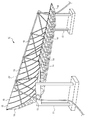
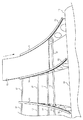
図1は、本発明の実施形態に係る太陽熱発電用集光装置10の斜視図である。図1に示すように、太陽熱発電用集光装置10は主に、地盤上の架台11,12と、架台11,12により回転可能に支持された軸部13と、軸部13にその長さ方向に間隔を置いて固定された複数のアーム部14と、アーム部14によって支持された複数の反射板15とを備える。反射板15の反射面は、軸部13に対して垂直な断面において放物線状となる放物柱面に形成されている。
FIG. 1 is a perspective view of a
図1に示すように、反射板15の前方には、集熱管20が軸部13と平行に支持されている。この集熱管20内には例えばオイルなどの液体が流される。液体は、ポンプ(図示せず)により循環される。
As shown in FIG. 1, a
太陽熱発電用集光装置10は、反射板15を用いて集熱管20に太陽光を集光させ、集熱管20内を流れる液体を加熱する。太陽熱発電用集光装置10により加熱された液体は、熱交換器に送られる。熱交換器は、加熱された液体を用いて蒸気を発生させ、この蒸気を蒸気タービンに送る。蒸気タービンは、その蒸気を用いてタービンを回転させ、発電を行う。
The concentrating
太陽熱発電用集光装置10は、軸部13周りに反射板15を回転させる回転装置(図示せず)を備えてもよい。例えば太陽の位置に応じて反射板15を回転させることにより、効率的に液体を加熱することができ、その結果発電効率を向上できる。
The solar power
図2は、太陽熱発電用集光装置10の正面図である。図3は、図2に示す太陽熱発電用集光装置10のA−A断面図である。
FIG. 2 is a front view of the concentrating
図2に示すように、本実施形態に係る太陽熱発電用集光装置10では、地盤上に架台11,12が立設されており、該架台11,12により軸部13の両端が支持されている。軸部13は、例えば直径数百mm(例えば500mm乃至700mm、例えば600mm)程度の例えばスチール製パイプであってよい。
As shown in FIG. 2, in the
軸部13には、その長さ方向に所定の間隔をおいて、複数のアーム部14が固定されている。アーム部14は、厚さ数mm(例えば6mm)程度の板状体であり、例えばスチール等により形成されてよい。図3に示すように、アーム部14は、その一方の側面が放物線状となるように形成されている。軸部13には、所定の間隔ごとアーム部14を軸部13に取り付けるためのブラケット部31が形成されており、アーム部14は、ボルト32およびナットを用いて該ブラケット部31に固定される。アーム部14は、例えば溶接により軸部13のブラケット部31に固定されてもよい。平板状のアーム部14を軸部13に固定しただけの単純な構造を採用することにより、例えば上述の特許文献1に記載されるようにパイプトラス構造を採用した場合と比較して、パイプの接合に多くの労力とコストを要することなく製造コストを低減でき、また、搬送時に嵩張らないようにすることができるので、搬送コストを低減できる。
A plurality of
本実施形態では、図2に示すように、軸部13から上方向に13個のアーム部14が延設されており、軸部13から下方向も13個のアーム部14が延設されている。軸部13の長さ方向に隣接する2つのアーム部14間ごとに、1枚の反射板15が設けられる。従って、軸部13の上方に12枚の反射板15が設けられ、軸部13の下方にも12枚の反射板15が設けられている。軸部13の上下に並ぶ2枚の反射板15は、軸部13を対称軸として線対称に配置されており、放物柱面状の反射面を形成している。
In the present embodiment, as shown in FIG. 2, 13
図4は、反射板15の断面構造を説明するための図である。図4に示すように、反射板15は、可撓性平板40上にフィルムミラー41を貼り合わせた構造を有する。可撓性平板40は、例えば厚さ数mm(例えば1mm乃至2mm)程度の金属板(例えばスチール板またはアルミ板)であってよい。フィルムミラー41は、可撓性のフィルム基材42上に反射層43が設けられた構造を有する。フィルム基材42は、従来公知の樹脂製基材であってよく、例えばアクリル系フィルムやポリエステル系フィルムであってよい。反射層43は、フィルム基材42上に蒸着により形成される金属反射層(例えば銀反射層)であってよい。以上のように形成された反射板15は、可撓性を有する。
FIG. 4 is a diagram for explaining a cross-sectional structure of the reflecting
本実施形態に係る太陽熱発電用集光装置10においては、取り付け前において平板状の反射板15をアーム部14への取り付け時に撓ませることにより、反射板15の反射面44が太陽光の集光に適した放物柱状曲面に形成される。アーム部14が反射板15を支持する支持体の詳細については後述する。
In the solar power
反射板15の前方には、図3に示すように支持部材21,22,23により集熱管20が支持されている。集熱管20は、その中心が反射板15の放物柱状反射面の焦点に位置するように支持される。放物柱面状の反射面で反射した太陽光は放物柱面の焦点に集光するので、このように集熱管20を配置することにより、太陽光を効率的に集熱管20に反射集光できる。
As shown in FIG. 3, the
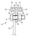
図5は、図3に示す太陽熱発電用集光装置10のB−B断面図である。図5は、アーム部14の内側端部の拡大断面図であり、反射板15を支持するための支持体を説明するための図である。本実施形態においては、アーム部14は、軸部13から延びる放物線状の側面を有する板状のアーム本体部53と、アーム本体部53の内側端部に沿って設けられた反射板15を固定支持するための反射板支持部50とから構成されている。
FIG. 5 is a BB cross-sectional view of the solar
反射板支持部50は、反射板の端部が挿入される2つの溝部54と、反射板支持部50をアーム本体部53に固定するための固定部55とを備える。固定部55にはボルト孔56が設けられており、該ボルト孔56に挿通されたボルト51とナット52を用いて反射板支持部50がアーム本体部53に固定されている。なお、本実施形態では、アーム本体部53と反射板支持部50を別々に形成し、ボルト51およびナット52を用いて両者を連結する構造としているが、アーム本体部53と反射板支持部50は一体的に形成された部材であってもよい。
The reflection
反射板支持部50の2つの溝部54は、断面コ字状の溝であり、所定の間隔を置いて対向する第1面57および第2面58と、底面59とから構成されている。2つの溝部54は、底面59を間に介して互いに逆方向に開口するように形成されている。第1面57は、第2面58よりも放物柱面の内側方向、すなわち第2面58よりも集熱管側に位置している。
The two
本実施形態において、第1面57は、反射板15の反射面44の曲面形状を規定する「反射面形成面」としての役割を有する。具体的には、第1面57は、軸部に対して垂直な断面において放物線状となる放物柱面に形成されている。組立前においては反射板15は平板状であるが、組み立て時に第1面57に沿って反射板15の反射面44を撓ませることで、反射面44が所定の放物柱面に形成される。
In the present embodiment, the
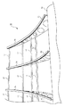
図6は、隣接する2つのアーム部14a,14bにより、1枚の反射板15が支持されている様子を示す。図6に示すように、一方のアーム部14aの反射板支持部50aが有する1つの溝部54aと、隣接する他方のアーム部14bの反射板支持部50bが有する1つの溝部54bとが対向しており、それら2つの溝部54a,54bに反射板15の両端を挿入することで、反射板15が曲面形状に撓んだ状態でアーム部14a,14bにより支持される。
FIG. 6 shows a state in which one reflecting
ここで、本実施形態では、反射板15の反射面44の両端部を反射面形成面である第1面57a,57bに確実に密着させるために、断面がくさび状に形成された板状部材60a,60bが反射板15の裏面45の両端部と第2面58a,58bとの間に圧入されている。本実施形態では、反射面44の両端部を溝部54a,54bに挿入しやすいように、第1面57a,57bと第2面58a,58bとの間隔を反射板15の厚みよりも大きくしている。従って、くさび状の板状部材60a、60bを圧入しない場合、反射板15の反射面44の両端部が反射面形成面である第1面57a,57bに密着せず、反射面44を所望の放物柱面に形成できないおそれがある。反射面44が設計通りの放物柱面になっていない場合、期待する集光効率を達成できず、発電効率が低下するおそれがある。
Here, in the present embodiment, a plate-like member whose cross section is formed in a wedge shape in order to ensure that both end portions of the
そこで、本実施形態のように、くさび状の板状部材60a,60bを用いて反射板15の両端部を第1面57a,57bに密着させることで、反射板15の反射面44を確実に所望の放物柱面に形成することができる。反射板15の反射面44を設計通りの曲面に形成することで、太陽光の集光効率が高くなり、発電効率を向上できる。くさび状の板状部材は、アーム部の長さ方向に分割されていてもよいし、アーム部の全長にわたって存在していてもよい。また、くさび状の板状部材を反射板の裏面と第2面との間に圧入後、ボルトを用いて板状部材および反射板を反射板支持部に固定してもよい。
Therefore, as in the present embodiment, the
図6に示す実施形態に代えて、第2面58a,58bを反射面形成面とし、第1面57a,57bと反射面44の両端部との間にくさび状の板状部材60a,60bを打ち込む構成としてもよい。しかしながら、この場合は、くさび状の板状部材60a,60bにより反射面44の面積が小さくなり、またくさび状の板状部材60a,60bを打ち込む際に反射面44を傷つけてしまうおそれがある。従って、図6に示す実施形態のように、反射面44が第1面57a,57b(反射面形成面)側に向き、裏面45が第2面58a,58b側に向くように反射板15を配置し、第2面58a,58bと反射板15の裏面45の両端部との間にくさび状の板状部材60a,60bを打ち込む構成とするのが望ましい。
Instead of the embodiment shown in FIG. 6, the
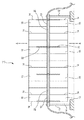
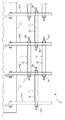
図7は、太陽熱発電用集光装置10から反射板を外した状態を示す。図7に示すように、本実施形態に係る太陽熱発電用集光装置10においては、軸部13の長さ方向に隣接する2つのアーム部14の間に、スペーサ17が設けられている。スペーサ17は、中空のパイプ状の部材であり、熱膨張を考慮して軸部13およびアーム部14と同じ材料(例えばスチール)で形成されることが好ましい。本実施形態では、一組の隣接するアーム部14間に4本のスペーサ17が設けられているが、スペーサ17の数は特に限定されず、アーム部14の長さ等に応じて適宜変更されてよい。図7に示すように、一組の隣接するアーム部14間に設けられる複数のスペーサ17は、アーム部14の剛性を向上するために、アーム部14の内側と外側とに交互に設けられることが好ましい。
FIG. 7 shows a state where the reflector is removed from the solar power
本実施形態では、上述したように、軸部13に板状のアーム部14を固定しただけの単純な構成を採用しているため、安価な太陽熱発電用集光装置を実現できる。しかしながら、単に軸部13に板状のアーム部14を固定しただけであると、アーム部14の剛性が十分に確保されないおそれがある。アーム部14の剛性が十分でない場合、軸部13の近傍では隣接するアーム部14の間隔を所望の設計値に制御できるかもしれないが、軸部13から離れるにつれてアーム部14の撓み等に起因して隣接する2つのアーム部14の間隔に設計値からのズレが生じるおそれがある。この場合、隣接する2つのアーム部14の反射板支持部50の溝部に反射板を挿入することが難しくなる。また、アーム部14の剛性が十分でない場合、例えば強風時にアーム部14が大きく撓み、2つの隣接するアーム部14間に設けた反射板に歪み等の異常が生じるおそれもある。
In the present embodiment, as described above, since a simple configuration in which the plate-
そこで、本実施形態に係る太陽熱発電用集光装置10のように、軸部13の長さ方向に隣接する2つのアーム部14の間にスペーサ17を設けることにより、アーム部14の間隔を所定の間隔に規定するとともに、アーム部14の剛性を確保することができる。
Therefore, as in the solar power
図8は、スペーサ17の固定方法を説明するための図である。図8では、図示を簡略化するために、一列のスペーサ17のみを図示している。図8に示すように、軸部13にはその長さ方向に第1アーム部14(1)、第2アーム部14(2)・・・第13アーム部14(13)が設けられており、隣接するアーム部間にはそれぞれ、第1スペーサ17(1)、第2スペーサ17(2)・・・第12スペーサ17(12)が設けられている。各スペーサ17は、隣接する2つのアーム部によって挟まれており、その長さはアーム部の間隔が所定値になるように設計されている。本実施形態では、第1スペーサ17(1)、第2スペーサ17(2)・・・第12スペーサ17(12)は、一方の最外側の第1アーム部14(1)から他方の最外側の第13アーム部14(13)まで一直線に設けられている。
FIG. 8 is a diagram for explaining a method of fixing the
上述したように、各スペーサ17は中空のパイプ状に形成されている。また、各アーム部14のスペーサ設置位置には、孔25が形成されている。孔25の孔径は、スペーサ17の外径よりも小さい。本実施形態において、スペーサ17は、該スペーサの内部と隣接する2つのアーム部14の孔25とに挿通されたロッド23により保持される。ロッド23は、第1アーム部14(1)、第2アーム部14(2)・・・第13アーム部14(13)の孔と、第1スペーサ17(1)、第2スペーサ17(2)・・・第12スペーサ17(12)の内部とを貫通するように設けられている。このロッド23は、一方の最外側の第1アーム部14(1)の外側から他方の最外側の第13アーム部14(13)の外側まで一直線に延びている。ロッド23の両端部23a,23bにはねじが切られている。ロッド23の一端部23aのねじにナット19aを嵌合させ回転させることで、ナット19aが第1アーム部14(1)に締め付けられ、ロッド23の一端部が第1アーム部14(1)に固定される。また、ロッド23の他端部23bのねじにナット19bを嵌合させ回転させることで、ナット19bが第13アーム部14(13)に締め付けられ、ロッド23の他端部が第13アーム部14(13)に固定される。ロッド23の両端部23a,23bをナット19a,19bで締め付けると、スペーサ17によりアーム部14の間隔が所定値に規定され、また第1アーム部14(1)、第2アーム部14(2)・・・第13アーム部14(13)の剛性が向上する。
As described above, each
図9は、アーム部14間にスペーサ17を設ける様子を示す。平板状のアーム部14は、軸部13から取り外された状態で設置場所に搬送される。太陽熱発電用集光装置10を設置する際には、まず地盤上に架台11,12(図1参照)を設置し、該架台11,12に軸部13を支持する。次に、軸部13にアーム部14を固定する。次に、図9に示すように、ロッド23をアーム部14の孔25とスペーサ17の内部とに交互に挿通しながら、一方の最外側のアーム部14から他方の最外側のアーム部14までロッド23を貫通させる。次に、ロッド23の両端部23a,23bをナット19a,19bで締め付ける。全てのスペーサを取り付けると、図7に示すような状態となる。
FIG. 9 shows how the
図10は、アーム部14間に反射板15を設ける様子を示す。本実施形態では、工場で製造された反射板15が平板の状態で設置場所に搬送される。そして、図10に示すように、隣接する2つのアーム部14の反射板支持部50の溝部に、アーム部14の延設先端部分から反射板15の両端を挿入する。反射板15の挿入完了後、反射板支持部50の第2面と反射板15の裏面の両端部との間にくさび状板状部材(図示せず)を打ち込む。これにより、反射板15の反射面の両端部が反射板支持部50の反射面形成面(第1面)に密着し、反射板15の反射面を所望の放物柱面に形成できる。
FIG. 10 shows a state in which the reflecting
以上説明したように、本実施形態に係る太陽熱発電用集光装置10によれば、平板状のアーム部14、スペーサ17およびロッド23を用いた単純な構成により反射板15の支持体を形成した。本実施形態においては、従来のパイプトラス構造よりも構造が簡素化されているため、反射板15の支持体を安価に形成できる。また、板状のアーム部14を用いているので、従来のパイプトラス構造のように搬送時に嵩張らず、搬送効率を高めることができる。一方、本実施形態では、スペーサ17およびロッド23を用いることにより、アーム部14の剛性を高めている。従って、本実施形態によれば、十分な剛性を確保しつつ、安価な太陽熱発電用集光装置を提供できる。
As described above, according to the solar power
さらに、本実施形態に係る太陽熱発電用集光装置10によれば、反射板15を平板の状態で設置場所に搬送することができるので、搬送時に嵩張ることがなく、搬送効率を向上することができる。また、工場においては単なる平板状の反射板15を製造し、設置現場において上記のように簡単な方法で精度の高い放物柱面状の反射面を形成できるので、工場において放物柱面状のガラス製反射鏡を製造する場合に比べて、製造コストを低減できる。
Furthermore, according to the solar power
なお、上述の実施形態では、ロッド23を用いて2つのアーム部14の間にスペーサ17を保持する構成としたが、スペーサ17の保持構造はこれて限定されない。例えば、ロッドを用いずに、スペーサ17の端部をアーム部14に例えば溶接やネジ止め等により固定することで、2つのアーム部14の間にスペーサ17を保持する構成を採用してもよい。
In the above-described embodiment, the
図11は、本発明の別の実施形態に係る太陽熱発電用集光装置10の構造を説明するための図である。図11は、図8と同様に、太陽熱発電用集光装置10から反射板を外した状態を示す。上述の実施形態では、図8に示すように、複数のスペーサ17が一方の最外側のアーム部14から他方の最外側の第アーム部14まで一直線に設けられており、それら複数のスペーサ17を一本のロッド23が一直線に貫通していた。一方、図11に示す実施形態では、複数のスペーサ17は、隣接する2つのアーム部14の組ごとに段違いに設けられている。本実施形態では、ロッド23は隣接する2つのアーム部14の間に設けられた1つのスペーサ17のみを貫通している。そして、ロッド23の両端をナット19a,19bで締め付けることでロッド23の両端が隣接する2つのアーム部14に固定され、スペーサ17により隣接する2つのアーム部14の間隔が所定値に規定される。すべての隣接する2つのアーム部14間に同じようにスペーサ17を設けることで、すべてのアーム部14の剛性が向上する。図11に示す実施形態のように、一直線に複数のスペーサ17を設けるのではなく、各スペーサ17を段違いに設けた場合、個々のロッド23の長さを短くできるので、搬送が容易になるという利点がある。
FIG. 11 is a view for explaining the structure of a solar
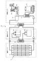
図12は、本実施形態に係る太陽熱発電用集光装置10を用いた太陽熱発電システム100を説明するための図である。図12に示すように、太陽熱発電システム100は、大きく分けて、集熱エリアと、蓄熱エリアと、発電エリアの3つのエリアから成る。
FIG. 12 is a diagram for explaining a solar thermal
集熱エリアは、主に上述した太陽熱発電用集光装置10と、集熱管20と、集熱管内の液体を循環させるポンプ(図示せず)とから構成される。集熱エリアにおいては、太陽熱発電用集光装置10により集熱管20に太陽光が集光され、集熱管20内を流れる液体が加熱される。加熱された液体は、蓄熱エリアに送られる。
The heat collection area is mainly composed of the solar power
蓄熱エリアは、主にホットタンク102と、コールドタンク103と、第1熱交換器109とから構成されている。必要発電量を上回る蓄熱があった際には、第1熱交換器109を通してコールドタンク103内の低温液体を温め、ホットタンク102へ移動させ、蓄熱させる。加熱された液体の熱をホットタンク102を用いて蓄えておくことにより、集熱が不足した際や太陽光が得られない夜間の発電が可能となる。
The heat storage area mainly includes a
発電エリアは、主に蒸気タービン104と、発電機106と、第2熱交換器111と、第3熱交換器112と、冷却タワー113とから構成される。第2熱交換器111は、加熱された液体を用いて蒸気を発生させ、蒸気タービン104は該蒸気によりタービンを回転させる。発電機106は、蒸気タービン104の回転により発電し、送電線108を介して送電する。第3熱交換器112は蒸気を液体に戻し、冷却タワー113は、該液体を冷却する。
The power generation area mainly includes a
上述した安価な太陽熱発電用集光装置10を用いることにより、太陽熱発電システム100の施工コストを低減することができる。
The construction cost of the solar thermal
以上、本発明を実施の形態をもとに説明した。この実施の形態は例示であり、それらの各構成要素や各処理プロセスの組合せにいろいろな変形例が可能なこと、またそうした変形例も本発明の範囲にあることは当業者に理解されるところである。 The present invention has been described based on the embodiments. This embodiment is an exemplification, and it will be understood by those skilled in the art that various modifications can be made to combinations of the respective constituent elements and processing processes, and such modifications are also within the scope of the present invention. is there.
10 太陽熱発電用集光装置、 13 軸部、 14 アーム部、 15 反射板、 17 スペーサ、 20 集熱管、 23 ロッド、 25 孔、 31 ブラケット部、 40 可撓性平板、 41 フィルムミラー、 42 フィルム基材、 43 反射層、 44 反射面、 50 反射板支持部、 53 アーム本体部、 54 溝部、 57 第1面、 58 第2面、 100 太陽熱発電システム、 104 蒸気タービン、 106 発電機。
DESCRIPTION OF
Claims (7)
前記軸部にその長さ方向に間隔を置いて固定された複数のアーム部と、
隣接する2つのアーム部により支持された太陽光を反射集光する反射板と、
隣接する2つのアーム部の間に設けられた、該2つのアーム部の間隔を規定するためのスペーサと、
を備えることを特徴とする太陽熱発電用集光装置。 A shaft portion supported by the gantry,
A plurality of arm portions fixed to the shaft portion at intervals in the length direction;
A reflector that reflects and collects sunlight supported by two adjacent arm parts;
A spacer provided between two adjacent arm portions for defining an interval between the two arm portions;
Concentrating device for solar thermal power generation characterized by comprising.
前記アーム部には孔が形成されており、
前記スペーサの内部と隣接する2つのアーム部の孔とに挿通された、前記スペーサを隣接する2つのアーム部の間に保持するためのロッドをさらに備えることを特徴とする請求項1または2に記載の太陽熱発電用集光装置。 The spacer is formed hollow,
A hole is formed in the arm part,
3. The rod according to claim 1, further comprising a rod inserted through the inside of the spacer and a hole of two adjacent arm portions to hold the spacer between the two adjacent arm portions. The concentrating device for solar power generation as described.
前記ロッドの一端部が一方の最外側のアーム部に固定され、前記ロッドの他端部が他方の最外側のアーム部に固定されることを特徴とする請求項3に記載の太陽熱発電用集光装置。 The rod is provided so as to penetrate the holes of the plurality of arm portions and the inside of the plurality of spacers,
4. The solar power collector according to claim 3, wherein one end portion of the rod is fixed to one outermost arm portion, and the other end portion of the rod is fixed to the other outermost arm portion. Optical device.
前記太陽熱発電用集光装置により集光された光を受ける集熱管と、
前記集熱管内の加熱された液体を用いて発生した蒸気により回転する蒸気タービンと、
前記蒸気タービンの回転により発電する発電機と、
を備えることを特徴とする太陽熱発電システム。 Concentrator for solar power generation according to any one of claims 1 to 4,
A heat collecting tube for receiving the light collected by the solar power collector;
A steam turbine rotating by steam generated using the heated liquid in the heat collecting tube;
A generator for generating electricity by rotation of the steam turbine;
A solar thermal power generation system comprising:
軸部にその長さ方向に間隔を置いて複数のアーム部を固定するステップと、
隣接する2つのアーム部の間に、該2つのアーム部の間隔を規定するためのスペーサを設けるステップと、
を備えることを特徴とする支持体の製造方法。 A method for manufacturing a support for a reflector that reflects and collects sunlight,
Fixing a plurality of arm portions at intervals in the length direction of the shaft portion;
Providing a spacer between two adjacent arm portions to define a distance between the two arm portions;
A process for producing a support, comprising:
前記アーム部には孔が形成されており、
前記スペーサを設けるステップは、前記スペーサの内部と隣接する2つのアーム部の孔とにロッドを挿通して、前記スペーサを隣接する2つのアーム部の間に保持するステップを備えることを特徴とする請求項6に記載の支持体の製造方法。 The spacer is formed hollow,
A hole is formed in the arm part,
The step of providing the spacer includes a step of inserting a rod through the inside of the spacer and a hole of two adjacent arm portions to hold the spacer between the two adjacent arm portions. The manufacturing method of the support body of Claim 6.
Priority Applications (5)
| Application Number | Priority Date | Filing Date | Title |
|---|---|---|---|
| JP2012252557A JP2014102013A (en) | 2012-11-16 | 2012-11-16 | Light condensing device for solar power generation |
| CN201380070640.3A CN104919255A (en) | 2012-11-16 | 2013-09-17 | Light collection device for solar power generation |
| PCT/JP2013/005480 WO2014076859A1 (en) | 2012-11-16 | 2013-09-17 | Light collection device for solar power generation |
| EP13855823.4A EP2921798A4 (en) | 2012-11-16 | 2013-09-17 | Light collection device for solar power generation |
| US14/713,066 US20150252792A1 (en) | 2012-11-16 | 2015-05-15 | Solar-thermal collector |
Applications Claiming Priority (1)
| Application Number | Priority Date | Filing Date | Title |
|---|---|---|---|
| JP2012252557A JP2014102013A (en) | 2012-11-16 | 2012-11-16 | Light condensing device for solar power generation |
Publications (1)
| Publication Number | Publication Date |
|---|---|
| JP2014102013A true JP2014102013A (en) | 2014-06-05 |
Family
ID=50730797
Family Applications (1)
| Application Number | Title | Priority Date | Filing Date |
|---|---|---|---|
| JP2012252557A Pending JP2014102013A (en) | 2012-11-16 | 2012-11-16 | Light condensing device for solar power generation |
Country Status (5)
| Country | Link |
|---|---|
| US (1) | US20150252792A1 (en) |
| EP (1) | EP2921798A4 (en) |
| JP (1) | JP2014102013A (en) |
| CN (1) | CN104919255A (en) |
| WO (1) | WO2014076859A1 (en) |
Cited By (2)
| Publication number | Priority date | Publication date | Assignee | Title |
|---|---|---|---|---|
| JPWO2017002259A1 (en) * | 2015-07-02 | 2018-03-29 | 千代田化工建設株式会社 | Grounding structure of solar heat collector, solar heat collector and solar power generation system |
| KR20210067431A (en) * | 2019-11-29 | 2021-06-08 | 송정만 | Accumulating apparatus for solar energy with reduction of rotating unbalance |
Families Citing this family (4)
| Publication number | Priority date | Publication date | Assignee | Title |
|---|---|---|---|---|
| US10583933B2 (en) | 2016-10-03 | 2020-03-10 | General Electric Company | Method and apparatus for undercowl flow diversion cooling |
| JP2018084365A (en) * | 2016-11-24 | 2018-05-31 | 荒川電工株式会社 | Solar heat collector |
| SE541607C2 (en) * | 2017-12-01 | 2019-11-12 | Absolicon Solar Collector Ab | Method and arrangement for manufacturing a parabolic trough solar collector |
| US20230417455A1 (en) * | 2020-11-17 | 2023-12-28 | Greenetica Distribution S.R.L. | Modular solar concentrator |
Citations (6)
| Publication number | Priority date | Publication date | Assignee | Title |
|---|---|---|---|---|
| FR2483064A1 (en) * | 1980-05-23 | 1981-11-27 | Carbonaro Henri | Parabolic solar heat collector - has thin reflecting surfaces mounted on parabolic support rotatable about axis |
| JPS57185402A (en) * | 1981-05-01 | 1982-11-15 | Rca Corp | Curvature reflector structural body |
| US4611575A (en) * | 1984-03-07 | 1986-09-16 | Powell Roger A | Parabolic trough solar reflector |
| JP2008168020A (en) * | 2007-01-15 | 2008-07-24 | Misawa Homes Co Ltd | Plate-like member and assembly |
| WO2010006056A1 (en) * | 2008-07-09 | 2010-01-14 | Skyfuel, Inc. | Solar collectors having slidably removable reflective panels for use in solar thermal applications |
| WO2012057120A1 (en) * | 2010-10-25 | 2012-05-03 | イビデン株式会社 | Thermal collector tube, thermal collector and concentrated solar power system |
Family Cites Families (6)
| Publication number | Priority date | Publication date | Assignee | Title |
|---|---|---|---|---|
| US4135493A (en) * | 1977-01-17 | 1979-01-23 | Acurex Corporation | Parabolic trough solar energy collector assembly |
| US4678292A (en) * | 1981-05-01 | 1987-07-07 | Rca Corporation | Curved structure and method for making same |
| US8904774B2 (en) | 2008-08-22 | 2014-12-09 | Skyfuel, Inc. | Hydraulic-based rotational system for solar concentrators that resists high wind loads without a mechanical lock |
| US8322333B2 (en) * | 2009-04-01 | 2012-12-04 | Abengoa Solar Inc. | Torque transfer between trough collector modules |
| ES2337332B1 (en) * | 2009-07-17 | 2011-06-08 | Ct Ingenieros A.A.I., S.L. | SUPPORT STRUCTURE FOR SOLAR CYLINDRICAL - PARABOLIC COLLECTOR. |
| US20120204863A1 (en) * | 2010-02-17 | 2012-08-16 | Invention House, Llc | Solar Collector |
-
2012
- 2012-11-16 JP JP2012252557A patent/JP2014102013A/en active Pending
-
2013
- 2013-09-17 EP EP13855823.4A patent/EP2921798A4/en not_active Withdrawn
- 2013-09-17 CN CN201380070640.3A patent/CN104919255A/en active Pending
- 2013-09-17 WO PCT/JP2013/005480 patent/WO2014076859A1/en active Application Filing
-
2015
- 2015-05-15 US US14/713,066 patent/US20150252792A1/en not_active Abandoned
Patent Citations (6)
| Publication number | Priority date | Publication date | Assignee | Title |
|---|---|---|---|---|
| FR2483064A1 (en) * | 1980-05-23 | 1981-11-27 | Carbonaro Henri | Parabolic solar heat collector - has thin reflecting surfaces mounted on parabolic support rotatable about axis |
| JPS57185402A (en) * | 1981-05-01 | 1982-11-15 | Rca Corp | Curvature reflector structural body |
| US4611575A (en) * | 1984-03-07 | 1986-09-16 | Powell Roger A | Parabolic trough solar reflector |
| JP2008168020A (en) * | 2007-01-15 | 2008-07-24 | Misawa Homes Co Ltd | Plate-like member and assembly |
| WO2010006056A1 (en) * | 2008-07-09 | 2010-01-14 | Skyfuel, Inc. | Solar collectors having slidably removable reflective panels for use in solar thermal applications |
| WO2012057120A1 (en) * | 2010-10-25 | 2012-05-03 | イビデン株式会社 | Thermal collector tube, thermal collector and concentrated solar power system |
Cited By (4)
| Publication number | Priority date | Publication date | Assignee | Title |
|---|---|---|---|---|
| JPWO2017002259A1 (en) * | 2015-07-02 | 2018-03-29 | 千代田化工建設株式会社 | Grounding structure of solar heat collector, solar heat collector and solar power generation system |
| EP3318815A4 (en) * | 2015-07-02 | 2018-11-14 | Chiyoda Corporation | Solar thermal collector grounding structure, solar thermal collector and solar thermal generator system |
| KR20210067431A (en) * | 2019-11-29 | 2021-06-08 | 송정만 | Accumulating apparatus for solar energy with reduction of rotating unbalance |
| KR102335901B1 (en) * | 2019-11-29 | 2021-12-03 | 송정만 | Accumulating apparatus for solar energy with reduction of rotating unbalance |
Also Published As
| Publication number | Publication date |
|---|---|
| EP2921798A1 (en) | 2015-09-23 |
| EP2921798A4 (en) | 2016-04-27 |
| US20150252792A1 (en) | 2015-09-10 |
| CN104919255A (en) | 2015-09-16 |
| WO2014076859A1 (en) | 2014-05-22 |
Similar Documents
| Publication | Publication Date | Title |
|---|---|---|
| WO2014076859A1 (en) | Light collection device for solar power generation | |
| JP5695894B2 (en) | Solar collector | |
| US9057543B2 (en) | Solar collector module | |
| US8132391B2 (en) | Thin mirror with truss backing and mounting arrangement therefor | |
| US9765991B2 (en) | Trough solar collector module | |
| US20160003496A1 (en) | Modular solar field | |
| WO2015130808A1 (en) | Mirror collector for parabolic solar trough | |
| WO2011157795A1 (en) | Solar collector assembly with parabolic reflector and reflector holder, method for manufacturing the solar collector assembly and use of the solar collector assembly | |
| EP2962047B1 (en) | Solar unit assembly and a method for constructing such an assembly | |
| US8490620B1 (en) | In-ground solar trough | |
| WO2017184893A1 (en) | Mirror collector for parabolic solar trough | |
| US20150247490A1 (en) | Solar-thermal collector | |
| WO2013084016A1 (en) | Supporting structure for a parabolic trough of solar collectors | |
| AU2012354665B2 (en) | Solar heat receiver, method for assembling same, and solar heat power generation system with solar heat receiver | |
| CN103697612A (en) | Stretching and slot type photo-thermal power generating heat collector torque tube structure | |
| CN203518271U (en) | Collecting lens with heat collecting pipe as rotation shaft | |
| CA2748635A1 (en) | Parabolic solar concentrating units, corresponding systems and method for their manufacturing, uses thereof | |
| WO2012111008A9 (en) | Support structure for solar concentrator | |
| JP2012007420A (en) | Solar heat absorption panel and roof structure for building | |
| WO2019166672A1 (en) | Arm for supporting a solar collector | |
| CN103335420B (en) | Collecting lens with heat collecting pipe as axis of rotation | |
| EP3121529A1 (en) | Support structure for supporting a mirror, solar collector assembly with the support structure, method for manufacturing the solar collector assembly and use of the solar collector assembly for a solar field | |
| EP3121530A1 (en) | Torque tube of a support structure for supporting a mirror; solar collector assembly with the support structure and use of the solar collector assembly for solar field |
Legal Events
| Date | Code | Title | Description |
|---|---|---|---|
| A621 | Written request for application examination |
Free format text: JAPANESE INTERMEDIATE CODE: A621 Effective date: 20151029 |
|
| A131 | Notification of reasons for refusal |
Free format text: JAPANESE INTERMEDIATE CODE: A131 Effective date: 20160705 |
|
| A02 | Decision of refusal |
Free format text: JAPANESE INTERMEDIATE CODE: A02 Effective date: 20170110 |