JP2014101877A - Heat storage device - Google Patents
Heat storage device Download PDFInfo
- Publication number
- JP2014101877A JP2014101877A JP2013139738A JP2013139738A JP2014101877A JP 2014101877 A JP2014101877 A JP 2014101877A JP 2013139738 A JP2013139738 A JP 2013139738A JP 2013139738 A JP2013139738 A JP 2013139738A JP 2014101877 A JP2014101877 A JP 2014101877A
- Authority
- JP
- Japan
- Prior art keywords
- adsorber
- reducing agent
- temperature
- storage device
- urea
- Prior art date
- Legal status (The legal status is an assumption and is not a legal conclusion. Google has not performed a legal analysis and makes no representation as to the accuracy of the status listed.)
- Granted
Links
Images

Classifications
-
- Y—GENERAL TAGGING OF NEW TECHNOLOGICAL DEVELOPMENTS; GENERAL TAGGING OF CROSS-SECTIONAL TECHNOLOGIES SPANNING OVER SEVERAL SECTIONS OF THE IPC; TECHNICAL SUBJECTS COVERED BY FORMER USPC CROSS-REFERENCE ART COLLECTIONS [XRACs] AND DIGESTS
- Y02—TECHNOLOGIES OR APPLICATIONS FOR MITIGATION OR ADAPTATION AGAINST CLIMATE CHANGE
- Y02A—TECHNOLOGIES FOR ADAPTATION TO CLIMATE CHANGE
- Y02A50/00—TECHNOLOGIES FOR ADAPTATION TO CLIMATE CHANGE in human health protection, e.g. against extreme weather
- Y02A50/20—Air quality improvement or preservation, e.g. vehicle emission control or emission reduction by using catalytic converters
-
- Y—GENERAL TAGGING OF NEW TECHNOLOGICAL DEVELOPMENTS; GENERAL TAGGING OF CROSS-SECTIONAL TECHNOLOGIES SPANNING OVER SEVERAL SECTIONS OF THE IPC; TECHNICAL SUBJECTS COVERED BY FORMER USPC CROSS-REFERENCE ART COLLECTIONS [XRACs] AND DIGESTS
- Y02—TECHNOLOGIES OR APPLICATIONS FOR MITIGATION OR ADAPTATION AGAINST CLIMATE CHANGE
- Y02T—CLIMATE CHANGE MITIGATION TECHNOLOGIES RELATED TO TRANSPORTATION
- Y02T10/00—Road transport of goods or passengers
- Y02T10/10—Internal combustion engine [ICE] based vehicles
- Y02T10/12—Improving ICE efficiencies
Landscapes
- Exhaust Gas After Treatment (AREA)
Abstract
Description
本発明は、車両の内燃機関の排気系に設けられた触媒を暖機する蓄熱装置に関する。 The present invention relates to a heat storage device for warming up a catalyst provided in an exhaust system of an internal combustion engine of a vehicle.
車両の排気系には、エンジンから排出される排気ガスに含まれる環境汚染物質(HC、CO、NOx等)を浄化するために、触媒等が設けられている。触媒には、浄化能力を活性化するための最適温度(活性温度)が存在する。エンジン始動時は、排気ガスの温度が低く、触媒の活性温度に達するまでに時間を要する。そこで、エンジン始動時等の排気ガスの温度が低いときに触媒の活性温度まで短時間で温度上昇させるために、触媒を暖機するための装置が必要である。この装置としては、エネルギロス(燃費ロス)を低減して暖機を行うために、化学反応の反応熱を利用した蓄熱装置がある。特許文献1には、化学反応の反応熱を利用した蓄熱装置として、化学反応の反応媒体としてアンモニアを使ったものが開示されている。 The exhaust system of the vehicle is provided with a catalyst or the like in order to purify environmental pollutants (HC, CO, NOx, etc.) contained in the exhaust gas discharged from the engine. The catalyst has an optimum temperature (activation temperature) for activating the purification capacity. When starting the engine, the temperature of the exhaust gas is low, and it takes time to reach the activation temperature of the catalyst. Therefore, a device for warming up the catalyst is required in order to raise the temperature in a short time to the activation temperature of the catalyst when the temperature of the exhaust gas is low, such as when the engine is started. As this device, there is a heat storage device using reaction heat of a chemical reaction in order to reduce energy loss (fuel consumption loss) and warm up. Patent Document 1 discloses a heat storage device using reaction heat of a chemical reaction that uses ammonia as a reaction medium for the chemical reaction.
蓄熱装置の化学反応で反応媒体としてアンモニアを使用する場合、アンモニアを吸着して貯蔵する吸着器とアンモニアと反応材とが反応して熱を発生する反応器との間でアンモニアを移動させる。アンモニアが吸着器の吸着材から分離すると、吸着器の温度が下がるため、吸着器から反応器にアンモニアが供給され難くなる。そのため、吸着器の温度を所望温度に保持しておく必要がある。しかし、従来の蓄熱装置の場合、ヒータ等の温調装置を別途設け、温調装置で温度調節している。このような温調装置を設けた場合、温調装置を作動させるための動力が必要となるので、エネルギロスとなる。また、このような蓄熱装置ではエンジン暖機後において、反応器に移動したアンモニアを排気ガスの熱で反応器から分離させ、吸着器へ回収することで連続的に使用可能としている。しかし、アンモニアの回収時には、高温となったアンモニアが吸着器へ流入するため、吸着器の温度が過度に高くならないように吸着器の温度を所望温度に保持しておく必要がある。そのため、吸着器の温度調節に部品を追加する必要がある。また、反応器と吸着器との間はパイプ(接続ライン)で繋がっており、このパイプを通ってアンモニアが移動する。このパイプ内に高温となったアンモニアが流れているときに、パイプを温度調節してアンモニアを冷却することも考えられる。しかし、この場合も、パイプを温度調節するための部品を追加する必要がある。 When ammonia is used as a reaction medium in a chemical reaction of a heat storage device, ammonia is moved between an adsorber that adsorbs and stores ammonia and a reactor that reacts with ammonia and a reaction material to generate heat. When ammonia is separated from the adsorbent of the adsorber, the temperature of the adsorber is lowered, so that it is difficult to supply ammonia from the adsorber to the reactor. Therefore, it is necessary to keep the temperature of the adsorber at a desired temperature. However, in the case of a conventional heat storage device, a temperature control device such as a heater is provided separately, and the temperature is adjusted by the temperature control device. When such a temperature control device is provided, power for operating the temperature control device is required, resulting in energy loss. Further, in such a heat storage device, after the engine is warmed up, ammonia that has moved to the reactor is separated from the reactor by the heat of the exhaust gas, and can be continuously used by collecting it in the adsorber. However, when ammonia is recovered, since the ammonia that has reached a high temperature flows into the adsorber, it is necessary to keep the temperature of the adsorber at a desired temperature so that the temperature of the adsorber does not become excessively high. Therefore, it is necessary to add parts to the temperature control of the adsorber. The reactor and the adsorber are connected by a pipe (connection line), and ammonia moves through this pipe. It is also conceivable to cool the ammonia by adjusting the temperature of the pipe when high temperature ammonia flows in the pipe. In this case, however, it is necessary to add a part for adjusting the temperature of the pipe.
そこで、本発明は、温調装置を別途設ける必要がない蓄熱装置を提供することを課題とする。 Then, this invention makes it a subject to provide the thermal storage apparatus which does not need to provide a temperature control apparatus separately.
本発明に係る蓄熱装置は、車両の内燃機関の排気系の少なくとも一部を暖機する蓄熱装置であって、排気系に配置され、アンモニアと化学反応して熱を発生させる反応材を有する反応器と、吸着材でアンモニアを吸着して貯蔵する吸着器と、反応器と吸着器とを接続する接続ラインとを備え、排気系には選択還元触媒と選択還元触媒に還元剤を供給する還元剤供給装置が少なくとも設けられ、吸着器又は接続ラインと還元剤供給装置の一部とが熱交換構造を有することを特徴とする。 A heat storage device according to the present invention is a heat storage device that warms up at least a part of an exhaust system of an internal combustion engine of a vehicle, and is a reaction that is disposed in the exhaust system and has a reaction material that chemically reacts with ammonia to generate heat. And a reduction line for supplying a reducing agent to the selective reduction catalyst and the selective reduction catalyst in the exhaust system, and a connection line connecting the reactor and the adsorber. An agent supply device is provided at least, and the adsorber or the connection line and a part of the reducing agent supply device have a heat exchange structure.
車両の内燃機関の排気系には、内燃機関の始動時などの排気系が低温時に早期に昇温させるための蓄熱装置がある。この蓄熱装置は、アンモニアと反応材とが化学反応して熱を発生させる反応器と、吸着材でアンモニアを吸着して貯蔵する吸着器と、反応器と吸着器との間でアンモニアを移動させるための接続ラインを備えている。特に、排気系には、選択還元触媒が設けられ、その選択還元触媒に還元剤を供給するための還元剤供給装置がある。還元剤供給装置は、一般的に、常温で貯蔵されている還元剤を供給する。この還元剤供給装置の一部(例えば、還元剤供給ライン、還元剤タンク)と吸着器又は接続ラインとが熱交換する構造を有している。このような熱交換構造を有することにより、吸着器又は接続ラインでは、還元剤供給装置の一部との熱交換によって温度調整される。この温調によって、吸着器を直接温めたり冷やしたりすることができ、又は、接続ラインで吸着器に流入する高温のアンモニアを冷やすことで吸着器の温度を所望温度に保持することができる。このように、この蓄熱装置では、排気系に備えられる選択還元触媒に還元剤を供給する還元剤供給装置を利用し、還元剤供給装置の一部と吸着器又は接続ラインとを熱交換構造とすることにより、温調装置を別途設けることなく、吸着器や接続ラインを温調できる。その結果、温調装置を作動させるための動力を必要とせず、エネルギロスを低減でき、温調装置を別途設けるコストも必要ない。また、触媒等の暖機を短時間で行うことができる。なお、吸着器と接続ラインを還元剤供給装置の各部で共に温調する場合も含むものとする。 2. Description of the Related Art An exhaust system for an internal combustion engine of a vehicle includes a heat storage device that quickly raises the temperature of the exhaust system such as when starting the internal combustion engine when the temperature is low. This heat storage device moves ammonia between a reactor in which ammonia and a reaction material chemically generate heat, an adsorber that adsorbs and stores ammonia with an adsorbent, and the reactor and the adsorber. A connection line is provided. In particular, the exhaust system is provided with a selective reduction catalyst, and there is a reducing agent supply device for supplying a reducing agent to the selective reduction catalyst. A reducing agent supply device generally supplies a reducing agent stored at room temperature. A part of the reducing agent supply device (for example, a reducing agent supply line, a reducing agent tank) and an adsorber or a connection line exchange heat. By having such a heat exchange structure, the temperature of the adsorber or the connection line is adjusted by heat exchange with a part of the reducing agent supply device. By this temperature control, the adsorber can be directly heated or cooled, or the temperature of the adsorber can be maintained at a desired temperature by cooling high-temperature ammonia flowing into the adsorber through the connection line. Thus, in this heat storage device, a reducing agent supply device that supplies a reducing agent to the selective reduction catalyst provided in the exhaust system is used, and a part of the reducing agent supply device and the adsorber or the connection line are combined with a heat exchange structure. By doing so, it is possible to adjust the temperature of the adsorber and the connection line without separately providing a temperature control device. As a result, power for operating the temperature control device is not required, energy loss can be reduced, and the cost of separately providing the temperature control device is not required. Moreover, warming up of a catalyst etc. can be performed in a short time. It should be noted that the case where the temperature of the adsorber and the connecting line are controlled together in each part of the reducing agent supply device is also included.
本発明の上記蓄熱装置では、吸着器と還元剤供給装置の一部とが熱交換構造を有すると好適である。 In the heat storage device of the present invention, it is preferable that the adsorber and a part of the reducing agent supply device have a heat exchange structure.
このような熱交換構造を有することにより、吸着器では、還元剤供給装置の一部との熱交換によって温度調整される。この温調によって、吸着器が直接温められて吸着器の温度が所望温度に保持されることにより、吸着材からのアンモニアの分離が促進される。その結果、吸着器から反応器にアンモニアがスムーズに供給され、反応器でアンモニアと反応材が化学反応して熱を発生させる。このように、この蓄熱装置では、排気系に備えられる選択還元触媒に還元剤を供給する還元剤供給装置を利用し、還元剤供給装置の一部と吸着器とを熱交換構造とすることにより、温調装置を別途設けることなく、吸着器を温調できる。 By having such a heat exchange structure, in the adsorber, the temperature is adjusted by heat exchange with a part of the reducing agent supply device. By this temperature control, the adsorber is directly warmed and the temperature of the adsorber is maintained at a desired temperature, thereby promoting the separation of ammonia from the adsorbent. As a result, ammonia is smoothly supplied from the adsorber to the reactor, and ammonia reacts with the reactant in the reactor to generate heat. Thus, in this heat storage device, by using a reducing agent supply device that supplies a reducing agent to the selective reduction catalyst provided in the exhaust system, a part of the reducing agent supply device and the adsorber have a heat exchange structure. The adsorber can be temperature controlled without providing a separate temperature control device.
本発明の上記蓄熱装置では、接続ラインと還元剤供給装置の一部とが熱交換構造を有すると好適である。 In the heat storage device of the present invention, it is preferable that the connection line and a part of the reducing agent supply device have a heat exchange structure.
このような熱交換構造を有することにより、接続ラインでは、還元剤供給装置との熱交換によって温度調整される。この温調によって、反応器で高温になったアンモニアが接続ラインを介して吸着器に戻ってくるときに、接続ライン内で高温のアンモニアを冷却して吸着器に戻すことができる。このように、この蓄熱装置では、排気系に設けられる還元剤供給装置を利用し、還元剤供給装置と接続ラインとを熱交換構造とすることにより、温調装置を別途設けることなく、反応器からの高温のアンモニアを冷却でき、吸着器が高温になるのを防止できる。 By having such a heat exchange structure, the temperature of the connection line is adjusted by heat exchange with the reducing agent supply device. By this temperature control, when the ammonia having a high temperature in the reactor returns to the adsorber via the connection line, the high-temperature ammonia can be cooled and returned to the adsorber in the connection line. Thus, in this heat storage device, the reducing agent supply device provided in the exhaust system is used, and the reducing agent supply device and the connection line have a heat exchange structure, so that the reactor is not provided separately. It is possible to cool the high-temperature ammonia from the furnace and prevent the adsorber from becoming hot.
本発明の上記蓄熱装置では、還元剤は、尿素であり、吸着器と還元剤供給装置の一部との熱交換構造は、還元剤供給装置の還元剤供給ラインの一部を吸着器の外周面に巻く構造又は吸着器内に配設する構造としてもよい。 In the above heat storage device of the present invention, the reducing agent is urea, and the heat exchange structure between the adsorber and a part of the reducing agent supply device is configured such that a part of the reducing agent supply line of the reducing agent supply device is connected to the outer periphery of the adsorber. A structure wound around a surface or a structure disposed in an adsorber may be used.
還元剤供給装置は、還元剤として尿素を供給し、還元剤(尿素)を移動させて供給するための還元剤供給ラインを備えている。蓄熱装置では、その還元剤供給ラインの一部を吸着器の外周面に巻く構造とすることによって、その還元剤供給ラインの一部と吸着器とで熱交換できる。また、蓄熱装置では、還元剤供給ラインの一部を吸着器内に配設する構造とすることによって、その還元剤供給ラインの一部と吸着器とで熱交換できる。このように、この蓄熱装置は、還元剤供給ラインの一部を利用して吸着器と熱交換できる構造にすることにより、吸着器を温調できるとともに、還元剤供給ライン(特に、ライン内を流れる尿素)も温調できる。温調されて尿素の温度が上昇すると、尿素が加水分解してアンモニアになり易くなる。 The reducing agent supply device includes a reducing agent supply line for supplying urea as a reducing agent and moving and supplying the reducing agent (urea). In the heat storage device, a part of the reducing agent supply line is wound around the outer peripheral surface of the adsorber, whereby heat can be exchanged between the reducing agent supply line and the adsorber. Further, in the heat storage device, a part of the reducing agent supply line is arranged in the adsorber, so that heat can be exchanged between the part of the reducing agent supply line and the adsorber. Thus, this heat storage device can adjust the temperature of the adsorber by using a part of the reducing agent supply line so that heat can be exchanged with the adsorber, and the reducing agent supply line (in particular, the inside of the line). Flowing urea) can also be temperature controlled. When the temperature is adjusted to increase the temperature of urea, urea is easily hydrolyzed to become ammonia.
本発明の上記蓄熱装置では、還元剤は、尿素であり、吸着器と還元剤供給装置の一部との熱交換構造は、吸着器を還元剤供給装置の還元剤タンク内に配置する構造としてもよい。 In the heat storage device of the present invention, the reducing agent is urea, and the heat exchange structure between the adsorber and a part of the reducing agent supply device is a structure in which the adsorber is disposed in the reducing agent tank of the reducing agent supply device. Also good.
還元剤供給装置は、還元剤として尿素を供給し、還元剤(尿素)を貯めておくための還元剤タンクを備えている。この蓄熱装置では、還元剤供給装置の還元剤タンク内に吸着器を配置する構造とすることによって、その還元剤タンクと吸着器とで熱交換できる。このように、この蓄熱装置は、還元剤タンクを利用して吸着器と熱交換できる構造にすることにより、吸着器を温調できるとともに、車両衝突時に吸着器が損傷しても還元剤タンク内にアンモニアが放出され、大気中へのアンモニア放出を防止できる。 The reducing agent supply device includes a reducing agent tank for supplying urea as a reducing agent and storing the reducing agent (urea). In this heat storage device, the adsorber is arranged in the reducing agent tank of the reducing agent supply device, so that heat can be exchanged between the reducing agent tank and the adsorber. In this way, this heat storage device can control the temperature of the adsorber by adopting a structure that can exchange heat with the adsorber using the reducing agent tank, and even if the adsorber is damaged during a vehicle collision, Ammonia is released into the atmosphere, and ammonia release into the atmosphere can be prevented.
本発明の上記蓄熱装置では、還元剤は、尿素であり、接続ラインと還元剤供給装置の一部との熱交換構造は、接続ラインの一部を還元剤供給装置の還元剤タンク内に配置する構造としてもよい。このように、この蓄熱装置は、還元剤タンク内に接続ラインの一部を配置して熱交換できる構造にすることにより、反応器からの高温のアンモニアを還元剤タンク内で効果的に冷却できる。 In the above heat storage device of the present invention, the reducing agent is urea, and the heat exchange structure between the connection line and a part of the reducing agent supply device is such that a part of the connection line is disposed in the reducing agent tank of the reducing agent supply device. It is good also as a structure to do. Thus, this heat storage device can effectively cool the high-temperature ammonia from the reactor in the reducing agent tank by arranging a part of the connection line in the reducing agent tank so that heat can be exchanged. .
本発明の上記蓄熱装置では、還元剤タンク内に配置される接続ラインの一部は、車両が衝突したときに発生する衝撃力によって破壊され易い構造を有すると好適である。このように、この蓄熱装置では、還元剤タンク内に配設される接続ラインの一部が車両衝突の衝撃力によって破壊され易い構造とすることにより、車両衝突時にその部分が他の箇所より優先して破壊されるので、その破壊された箇所からアンモニアが還元剤タンク内に放出され、大気中へのアンモニア放出を防止できる。 In the heat storage device of the present invention, it is preferable that a part of the connection line arranged in the reducing agent tank has a structure that is easily broken by an impact force generated when the vehicle collides. As described above, in this heat storage device, a part of the connection line arranged in the reducing agent tank is easily broken by the impact force of the vehicle collision, so that the part has priority over other parts at the time of the vehicle collision. As a result, the ammonia is released into the reducing agent tank from the destroyed part, and the release of ammonia into the atmosphere can be prevented.
本発明によれば、排気系に備えられる選択還元触媒に還元剤を供給する還元剤供給装置を利用し、還元剤供給装置の一部と吸着器又は接続ラインとを熱交換構造とすることにより、温調装置を別途設けることなく、吸着器や接続ラインを温調できる。 According to the present invention, by using a reducing agent supply device that supplies a reducing agent to a selective reduction catalyst provided in an exhaust system, a part of the reducing agent supply device and an adsorber or a connection line have a heat exchange structure. The adsorber and the connection line can be temperature-controlled without separately providing a temperature control device.
以下、図面を参照して、本発明に係る蓄熱装置の実施の形態を説明する。なお、各図において同一又は相当する要素については同一の符号を付し、重複する説明を省略する。 Hereinafter, an embodiment of a heat storage device according to the present invention will be described with reference to the drawings. In addition, the same code | symbol is attached | subjected about the element which is the same or it corresponds in each figure, and the overlapping description is abbreviate | omitted.
本実施の形態では、本発明に係る蓄熱装置を、車両のエンジンの排気系に設けられる排気浄化システムに備えられる蓄熱装置に適用する。本実施の形態に係る排気浄化システムは、エンジン(特に、ディーゼルエンジン)から排出される排気ガス中に含まれる有害物質(環境汚染物質)を浄化するシステムである。本実施の形態に係る排気浄化システムは、触媒のDOC[Diesel Oxidation Catalyst]とSCR[SelectiveCatalytic Reduction]及びフィルタのDPF[Diesel ParticulateFilter]を備えており、触媒を暖機するための化学蓄熱装置も備えている。また、本実施の形態に係る排気浄化システムは、SCRが尿素SCRシステムであり、還元剤として尿素水を噴霧する尿素噴霧システムも備えている。 In the present embodiment, the heat storage device according to the present invention is applied to a heat storage device provided in an exhaust purification system provided in an exhaust system of a vehicle engine. The exhaust purification system according to the present embodiment is a system that purifies harmful substances (environmental pollutants) contained in exhaust gas discharged from an engine (particularly a diesel engine). The exhaust purification system according to the present embodiment includes a catalyst DOC [Diesel Oxidation Catalyst] and an SCR [Selective Catalytic Reduction] and a filter DPF [Diesel Particulate Filter], and also includes a chemical heat storage device for warming up the catalyst. ing. The exhaust purification system according to the present embodiment also includes a urea spray system in which the SCR is a urea SCR system and sprays urea water as a reducing agent.
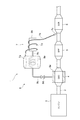
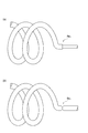
図1及び図2を参照、本実施の形態に係る排気浄化システム1について説明する。図1は、本実施の形態に係る蓄熱装置を備えた排気浄化システムの概略構成図である。図2は、図1の尿素タンク内に配設される接続ラインのパイプ構造の例であり、(a)が段差を有する構造であり、(b)が切欠きを有する構造である。 With reference to FIG.1 and FIG.2, the exhaust gas purification system 1 which concerns on this Embodiment is demonstrated. FIG. 1 is a schematic configuration diagram of an exhaust purification system including a heat storage device according to the present embodiment. FIG. 2 is an example of a pipe structure of a connection line disposed in the urea tank of FIG. 1, (a) is a structure having a step, and (b) is a structure having a notch.
排気浄化システム1は、エンジン2の排気側に接続された排気通路3の上流側から下流側に向けて、ディーゼル酸化触媒(DOC)4、ディーゼル排気微粒子除去フィルタ(DPF)5及び選択還元触媒(SCR)6を有しており、そのSCR6用の尿素噴霧システム7を有している。本実施の形態では、エンジン2が特許請求の範囲に記載する内燃機関に相当し、DOC4及びSCR6が特許請求の範囲に記載する触媒に相当し、SCR6が特許請求の範囲に記載する選択還元触媒に相当し、尿素噴霧システム7が特許請求の範囲に記載する還元剤供給装置に相当する。
The exhaust purification system 1 includes a diesel oxidation catalyst (DOC) 4, a diesel exhaust particulate removal filter (DPF) 5, and a selective reduction catalyst (from the upstream side to the downstream side of the
DOC4は、排気ガス中に含まれるHCやCO等を酸化する触媒である。DPF5は、排気ガス中に含まれるPMを捕集して取り除くフィルタである。SCR6は、還元剤である尿素水から加水分解されたアンモニア(NH3)と排気ガス中に含まれるNOxとを化学反応させることによって、NOxを還元して浄化する触媒である。 DOC4 is a catalyst that oxidizes HC, CO, etc. contained in the exhaust gas. The DPF 5 is a filter that collects and removes PM contained in the exhaust gas. The SCR 6 is a catalyst that reduces and purifies NOx by chemically reacting ammonia (NH 3 ) hydrolyzed from urea water as a reducing agent and NOx contained in the exhaust gas.
尿素噴霧システム7は、排気通路3におけるSCR6の上流に尿素水(還元剤)を噴霧するためのシステムである。具体的には、尿素噴霧システム7は、ポンプ(図示せず)、尿素タンク7a、尿素噴霧ライン7b、インジェクタ7c等を備えている。尿素タンク7aは、尿素水を貯蔵するタンクである。ポンプが作動すると、尿素タンク7aから尿素水が尿素噴霧ライン7bに送り出される。尿素噴霧ライン7bは、尿素タンク7aとインジェクタ7cとを接続し、尿素タンク7aからインジェクタ7cまで尿素水を移動させる管路である。インジェクタ7cは、排気通路3におけるDPF5とSCR6との間に配設され、排気通路3内に尿素水を噴霧する。噴霧された尿素水は、排気ガス中に噴霧されることにより高温下で加水分解し、アンモニアになる。なお、本実施の形態では、尿素タンク7aが特許請求の範囲に記載する還元剤タンクに相当し、尿素噴霧ライン7bが特許請求の範囲に記載する還元剤供給ラインに相当する。
The
なお、尿素タンク7aは、車両における常温(例えば、25℃)となる箇所に設置され、例えば、トランクルーム内に設置される。したがって、尿素タンク7a(タンク内の尿素水)や尿素水が流れる尿素噴霧ライン7bは、通常、常温付近の温度となっている。この常温付近の尿素タンク7aや尿素噴霧ライン7bを利用して、蓄熱装置8(特に、吸着器8b)の温調を行う。この蓄熱装置8を温調するための構造については、後で詳細に説明する。
In addition, the
DOC4及びSCR6には、環境汚染物質の浄化能力を発揮できる温度領域、すなわち、活性温度が存在する。例えば、DOC4の活性温度の下限は150℃程度であり、SCR6の活性温度の下限は180℃程度である。一方、エンジン2の始動直後などは、エンジン2からの排出された直後の排気ガスの温度は100℃程度と比較的低温である。そこで、エンジン2の始動直後などでも、DOC4及びSCR6で浄化能力を発揮させるために、DOC4及びSCR6での温度を活性温度にする必要がある。そこで、排気浄化システム1は、触媒の暖機を行う蓄熱装置8も有している。なお、排気浄化システム1には、エンジン2から排出された排気ガスの温度(あるいは、触媒の温度)を検出する温度センサが設けられている。
The DOC 4 and the SCR 6 have a temperature range that can exhibit the ability to purify environmental pollutants, that is, an activation temperature. For example, the lower limit of the activation temperature of DOC4 is about 150 ° C, and the lower limit of the activation temperature of SCR6 is about 180 ° C. On the other hand, immediately after the
蓄熱装置8は、エネルギレスで触媒を暖機する化学蓄熱装置である。つまり、蓄熱装置8は、通常は排気ガスの熱(排熱)を蓄えておき、必要なときにその熱を使用して触媒を暖機する。蓄熱装置8は、排気通路3上で上流に位置する触媒であるDOC4において暖機を行う。蓄熱装置8は、反応器8a、吸着器8b、接続ライン8c、開閉弁8d等を備えている。
The
反応器8aは、DOC4の外周面に沿って設けられる。反応器8aは、アンモニアと化学反応する固体状又は粉末状の反応材が含有された成形体を有している。反応材としては、例えば、MgCl2、CaCl2、NiCl2、ZnCl2、SrCl2がある。
The
吸着器8bは、尿素噴霧ライン7bが配設される箇所において設置可能な箇所に設置される。吸着器8bは、アンモニアと物理吸着する吸着材としての活性炭が内蔵されている。したがって、吸着器8bでは、アンモニアが活性炭と物理吸着した状態で貯蔵されている。吸着器8bにおいてアンモニアを活性炭と物理吸着させたり、アンモニアを活性炭から分離させるためには、吸着器8bの温度を所望温度(例えば、常温付近)に維持する必要がある。この所望温度に維持するために、吸着器8bには温調が必要となる。
The
なお、吸着器8bには、内部の温度を検出する温度センサ(図示せず)と圧力を検出する圧力センサ(図示せず)が設けられている。この各センサで検出される温度と圧力が所定の条件を満たした場合に、反応器8aから吸着器8bにアンモニアが戻って、全てのアンモニアが活性炭と物理吸着した状態であると判断できる。この所定の条件については、従来から知られている周知の条件を適用する。
The
接続ライン8cは、反応器8aと吸着器8bとを接続し、反応器8aと吸着器8bとの間でアンモニアを移動させる管路である。接続ライン8cは、その一部が尿素タンク7a内を通るように配設される。開閉弁8dは、接続ライン8cの途中に配設される。開閉弁8dが開弁されると、接続ライン8cを介して反応器8aと吸着器8bとの間でアンモニアの移動が可能となる。なお、この開閉弁8dの開閉制御は、エンジン2を制御するECU[Electronic Control Unit](図示せず)等で行われる。
The
尿素噴霧システム7(特に、尿素タンク7a、尿素噴霧ライン7b)を利用した蓄熱装置8(特に、吸着器8b)を温調するための構造について説明する。この温調するための構造としては、尿素噴霧ライン7bの一部と吸着器8bとが熱交換する構造と、尿素タンク7aと接続ライン8cの一部とが熱交換する構造がある。
A structure for controlling the temperature of the heat storage device 8 (particularly the
尿素噴霧ライン7bの一部と吸着器8bとの熱交換構造について説明する。吸着器8bは、上記したように、尿素噴霧ライン7bが配設される箇所において設置可能な箇所に設置される。そして、尿素噴霧ライン7bにおける一部のパイプ7dが吸着器8bの外周面に沿って巻き付けられることによって、巻き付けられているパイプ7dと吸着器8bとの間で熱交換を行う構造である。この構造により、常温付近の尿素水が流れるパイプ7dによって吸着器8bを温めることができ、吸着器8bの温度を所望温度(例えば、常温付近)に維持して、吸着器8bにおいて活性炭からアンモニアの分離を促進できる。また、この構造により、吸着器8bによってパイプ7dを温めることができ、パイプ7d内を流れる尿素水の加水分解を促進できる。
A heat exchange structure between a part of the
なお、図1ではパイプ7dが吸着器8bに2〜3回程度巻き付けられている状態を描いているが、実際には、パイプ7dは吸着器8bに出来る限り多く巻き付けられている。また、パイプ7dは、吸着器8bに密着して巻き付けられる。吸着器8bに巻き付けられるパイプ7dの長さが長いほど、パイプ7dと吸着器8bとの熱交換が多く行われ、温調効果が高くなる。
Although FIG. 1 depicts a state in which the
尿素タンク7aと接続ライン8cの一部との熱交換構造について説明する。接続ライン8cは、上記したように、その一部が尿素タンク7a内を通るように配設される。そして、接続ライン8cにおける一部のパイプ8eが尿素タンク7a内に挿入されてループ状に配設されることによって、尿素タンク7a内のパイプ8eと尿素タンク7a内(特に、タンク内の尿素水)との間で熱交換を行う構造である。この構造により、パイプ8e内を流れる高温のアンモニア(反応器8aで再生され、吸着器8bに戻るアンモニア)を冷却でき、吸着器8bが高温になるのを防止できる。
A heat exchange structure between the
なお、図1ではパイプ8eが尿素タンク7a内で2〜3回程度ループしている状態を描いているが、実際には、パイプ8eは尿素タンク7a内で出来る限り多くループされている。尿素タンク7a内のパイプ8eの長さが長いほど、パイプ8eと尿素タンク7a内(タンク内の尿素水)との間で熱交換が多く行われ、温調効果が高くなる。
Although FIG. 1 depicts a state where the
さらに、尿素タンク7a内に挿入されているパイプ8eの所定の箇所が破壊され易い構造とするとよい。破壊され易い構造とは、車両が衝突したときに、衝突の衝撃力が接続ライン8cに作用し、それに応じて尿素タンク7a内のパイプ8eに応力がかかったときに、接続ライン8cにおける他の箇所より破壊し易いような構造である。破壊され易い構造は、例えば、その箇所が折れ易い構造、外れ易い構造、穴のあき易い構造である。
Furthermore, it is preferable that a predetermined portion of the
この破壊され易い構造としては、例えば、図2(a)に示すパイプ8e1のようにパイプ8e1の所定の箇所の段差を大きくしたり、図2(b)に示すパイプ8e2のようにパイプ8e2の所定の箇所に切欠きを設けた構造とする。このような段差や切欠きを、1本のパイプの途中に形成しもよいし、あるいは、径の異なる2本のパイプを接合したりあるいは端部を切欠いた2本のパイプを接合してもよい。
As the disrupted structure easy, for example, to increase the level difference of a predetermined portion of the
以上のように構成した排気浄化システム1における蓄熱装置8及びその温調機能についての動作を説明する。車両停止中(エンジン2が停止中)は、開閉弁8dは閉じられている。したがって、吸着器8bにおいて活性炭からアンモニアが分離していても、接続ライン8cを介してアンモニアが反応器8aに供給されない。
The operation of the
エンジン2が始動後、エンジン2から排出された排気ガスの温度が所定温度(DOC4やSCR6の活性温度より低い温度)より低いときには(エンジン2の始動直後など)、ECUによる制御によって開閉弁8dが開けられ、接続ライン8cを介してアンモニアが反応器8aに供給される。このとき、吸着器8bの圧力が反応器8aの圧力よりも高く、アンモニアが反応器8a側に移動する。反応器8aでは、供給されたアンモニアと成形体に含有される反応材(例えば、MgCl2)とが化学反応して化学吸着(配位結合)し、その成形体から熱を発生する。つまり、下記の反応式における左辺から右辺への反応が起こる。そして、反応器8aの成形体から発生した熱によってDOC4やSOC6の各温度が上昇し、排気ガス中の環境汚染物質の浄化に適した活性温度まで上昇する。
MgCl2+6NH3⇔MgCl2・6(NH3)+熱
When the temperature of the exhaust gas discharged from the
MgCl 2 + 6NH 3 ⇔MgCl 2 · 6 (NH 3 ) + heat
この際、尿素タンク7a内の尿素水が尿素噴霧ライン7bを通ってインジェクタ7cから噴射されていると、吸着器8bに巻き付けられている尿素噴霧ライン7bのパイプ7dと吸着器8bとの間で熱交換が行われる。これによって、吸着器8b内の活性炭よりアンモニアが分離されるに従って吸着器8bの温度が低下しようとするが、パイプ7dと吸着器8bとの熱交換によって吸着器8bが温められ、吸着器8bの温度低下が抑制され、吸着器8bの温度が所望温度に維持される。そのため、吸着器8b内の活性炭からのアンモニアの分離が促進され、吸着器8bから接続ライン8cを介して反応器8aにアンモニアがスムーズに供給される。その結果、反応器8aにおいてアンモニアと成形体に含有される反応材との化学反応がスムーズに行われ、熱の発生に時間がかかることが防止される。その結果、短時間で、DOC4やSOC6の各温度が活性温度まで上昇する。
At this time, if the urea water in the
エンジン2から排出された排気ガスの温度が所定温度(DOC4やSCR6の活性温度より高い温度)より高くなると、排気ガスの排熱が反応器8aの成形体に与えられることにより、アンモニアと反応材(MgCl2)とが分離し、高温のアンモニアが発生する。つまり、上記の反応式における右辺から左辺への反応が起こる。そして、分離したアンモニアは、反応器8aから接続ライン8cを介して吸着器8bに戻る。このとき、反応器8aの圧力が吸着器8bの圧力よりも高く、アンモニアが吸着器8b側に移動する。吸着器8bでは、活性炭がアンモニアを物理吸着して貯蔵する。
When the temperature of the exhaust gas discharged from the
この際、尿素タンク7a内(特に、タンク内の尿素水)と尿素タンク7aに挿入されている接続ライン8cのパイプ8eとの間で熱交換が行われる。これによって、反応器8aから出たアンモニアは高温であるが、尿素タンク7a内でのパイプ8eとの熱交換によって高温のアンモニアが冷却され、吸着器8bに戻ったアンモニアによって吸着器8bが高温になるのが抑制される。それに伴って、吸着器8bに巻き付けられている尿素噴霧ライン7bのパイプ7dが高温になるのも抑制される。
At this time, heat exchange is performed between the
上記したように、各センサで吸着器8bの温度と圧力が検出されており、この検出された温度と圧力が所定の条件を満たした場合、吸着器8bにおいて全てのアンモニアが活性炭と物理吸着した状態と判断される。このように判断された場合、ECUの制御によって、開閉弁8dが閉じられる。
As described above, the temperature and pressure of the
また、車両が衝突したときに、その衝突の衝撃力が接続ライン8cに作用した場合、尿素タンク7a内のパイプ8eにおける破壊され易い構造の箇所が破壊する。この破壊箇所からアンモニアが尿素タンク7a内に漏れ出すが、尿素タンク7a内の尿素水にアンモニアが溶け込む。その結果、アンモニアが大気中に放出されない。
Further, when the impact force of the collision acts on the
この排気浄化システム1(特に、蓄熱装置8の温調構造)によれば、排気浄化システム1に備えられる尿素噴霧システム7を利用し、尿素噴霧ライン7bのパイプ7dと吸着器8bとが熱交換する構造とすることにより、温調装置を別途設けることなく、吸着器8bを温調でき、吸着器8bでの活性炭からアンモニアの分離を促進できる。温調装置を別途設けないので、温調装置を作動させるための動力が必要とせず、エネルギロスを低減でき、温調装置を別途設けるコストも必要ない。また、DOC4やSCR6に対する暖機を短時間で行うことができる。さらに、尿素噴霧ライン7bのパイプ7dを吸着器8bの外周面に沿って巻き付ける構造とすることにより、尿素噴霧ライン7bで供給される尿素水の温度も温調できる。温調されて尿素水の温度が上昇すると、尿素水の加水分解も促進できる。
According to this exhaust purification system 1 (particularly, the temperature control structure of the heat storage device 8), the
また、排気浄化システム1によれば、排気浄化システム1に備えられる尿素噴霧システム7を利用し、尿素タンク7aと接続ライン8cのパイプ8eとが熱交換する構造とすることにより、温調装置を別途設けることなく、反応器8aから出た高温のアンモニアを冷却でき、吸着器8bが高温になるのを防止できる。特に、尿素タンク7a内にパイプ8eをループ状に配設して熱交換する構造にすることにより、パイプ8e内の高温のアンモニアを尿素タンク7a内で効果的に冷却できる。
Moreover, according to the exhaust gas purification system 1, the temperature control apparatus is configured by using the
また、排気浄化システム1によれば、尿素タンク7a内に配設される接続ライン8cのパイプ8eが車両衝突の衝撃力によって破壊され易い構造とすることにより、車両衝突時にその構造の箇所が他の箇所より優先して破壊されるので、その破壊された箇所からアンモニアが尿素タンク7a内に漏れ出し、大気中へのアンモニア放出を防止できる。
Further, according to the exhaust gas purification system 1, the
以上、本発明に係る実施の形態について説明したが、本発明は上記実施の形態に限定されることなく様々な形態で実施される。 As mentioned above, although embodiment which concerns on this invention was described, this invention is implemented in various forms, without being limited to the said embodiment.
例えば、本実施の形態では触媒としてDOCとSCR、フィルタとしてDPFを備える排気浄化システムに適用したが、触媒に還元剤を供給することで排気ガスを浄化するシステムであれば、他の様々な構成の排気浄化システムに適用できる。例えば、SCRに還元剤として軽油を供給することでNOxを還元するシステムに適用できる。 For example, in the present embodiment, the present invention is applied to an exhaust purification system including DOC and SCR as catalysts and DPF as a filter. However, various other configurations are possible as long as the system purifies exhaust gas by supplying a reducing agent to the catalyst. Applicable to exhaust gas purification systems. For example, the present invention can be applied to a system that reduces NOx by supplying light oil as a reducing agent to the SCR.
また、本実施の形態では触媒を暖機するためにDOCの外周面に蓄熱装置の反応器を配設する構成としたが、暖機対象の触媒に応じて他の箇所に配設してもよく、例えば、暖機対象の触媒をSCRとした場合にはSCRの上流側の排気通路の所定箇所やSCRの外周面に配設してもよいし、DOCの場合でもDOCの上流側の排気通路の所定箇所に配設してもよい。また、本実施の形態では蓄熱装置で触媒(DOC)を暖機する構成としたが、蓄熱装置によって直接暖機する対象は触媒に限られず、触媒上流に配置される分散板や排気管自体を温めることで排気ガスの温度を上昇させるようにしてもよい。 Further, in this embodiment, the reactor of the heat storage device is arranged on the outer peripheral surface of the DOC in order to warm up the catalyst. However, it may be arranged in other places depending on the catalyst to be warmed up. For example, if the catalyst to be warmed up is an SCR, it may be disposed at a predetermined location in the exhaust passage upstream of the SCR or the outer peripheral surface of the SCR, or even in the case of a DOC, the exhaust upstream of the DOC. You may arrange | position in the predetermined location of a channel | path. Further, in this embodiment, the catalyst (DOC) is warmed up by the heat storage device, but the target to be directly warmed up by the heat storage device is not limited to the catalyst, and the dispersion plate and the exhaust pipe itself arranged upstream of the catalyst are used. You may make it raise the temperature of exhaust gas by warming.
また、本実施の形態では吸着器と尿素噴霧システムの一部との熱交換構造として吸着器の外周面に尿素噴霧ラインのパイプを巻き付ける構成としたが、尿素噴霧ラインのパイプを吸着器内に挿入して配設したり、尿素タンクと吸着器とを接触させるように配置したり、図3に示すように尿素タンク7a内に吸着器8bを内蔵など、他の構成としてもよい。尿素タンク内に吸着器を内蔵した場合、車両衝突したときに、吸着器が破壊してアンモニアが漏れ出して、そのアンモニアが尿素タンクの尿素水に溶け込み、アンモニアが大気中に放出されない。
Further, in this embodiment, as a heat exchange structure between the adsorber and a part of the urea spray system, the urea spray line pipe is wound around the outer peripheral surface of the adsorber, but the urea spray line pipe is placed in the adsorber. Other arrangements may be employed, such as insertion and arrangement such that the urea tank and the adsorber are brought into contact with each other, or an
また、本実施の形態では接続ラインの一部と尿素タンクとの熱交換構造として尿素タンク内に接続ラインのパイプをループ状に配設する構成としたが、接続ラインのパイプを尿素タンクの外周面に巻きつける、尿素タンク内のパイプをループ以外の状態で配設するなど、他の構成としてもよい。 In the present embodiment, the pipe of the connection line is arranged in a loop shape in the urea tank as a heat exchange structure between a part of the connection line and the urea tank. Other configurations such as winding around the surface or arranging the pipe in the urea tank in a state other than the loop may be adopted.
1…排気浄化システム、2…エンジン、3…排気通路、4…ディーゼル酸化触媒(DOC)、5…ディーゼル排気微粒子除去フィルタ(DPF)、6…選択還元触媒(SCR)、7…尿素噴霧システム、7a…尿素タンク、7b…尿素噴霧ライン、7c…インジェクタ、7d…パイプ、8…蓄熱装置、8a…反応器、8b…吸着器、8c…接続ライン、8d…開閉弁、8e,8e1,8e2…パイプ。
DESCRIPTION OF SYMBOLS 1 ... Exhaust purification system, 2 ... Engine, 3 ... Exhaust passage, 4 ... Diesel oxidation catalyst (DOC), 5 ... Diesel exhaust particulate removal filter (DPF), 6 ... Selective reduction catalyst (SCR), 7 ... Urea spray system, 7a ... urea tank, 7b ... urea spray line, 7c ... injector, 7d ... pipe, 8 ... heat storage device, 8a ... reactor, 8b ... adsorber, 8c ... connection line, 8d ... off valve, 8e,
Claims (7)
前記排気系に配置され、アンモニアと化学反応して熱を発生させる反応材を有する反応器と、
吸着材でアンモニアを吸着して貯蔵する吸着器と、
前記反応器と前記吸着器とを接続する接続ラインと、
を備え、
前記排気系には選択還元触媒と前記選択還元触媒に還元剤を供給する還元剤供給装置が少なくとも設けられ、
前記吸着器又は前記接続ラインと前記還元剤供給装置の一部とが熱交換構造を有することを特徴とする蓄熱装置。 A heat storage device for warming up at least a part of an exhaust system of an internal combustion engine of a vehicle,
A reactor disposed in the exhaust system and having a reactant that chemically reacts with ammonia to generate heat;
An adsorber for adsorbing and storing ammonia with an adsorbent;
A connection line connecting the reactor and the adsorber;
With
The exhaust system is provided with at least a selective reduction catalyst and a reducing agent supply device for supplying a reducing agent to the selective reduction catalyst,
The heat storage device, wherein the adsorber or the connection line and a part of the reducing agent supply device have a heat exchange structure.
前記吸着器と前記還元剤供給装置の一部との熱交換構造は、前記還元剤供給装置の還元剤供給ラインの一部を前記吸着器の外周面に巻く構造又は前記吸着器内に配設する構造とすることを特徴とする請求項2に記載の蓄熱装置。 The reducing agent is urea;
The heat exchange structure between the adsorber and a part of the reducing agent supply device is a structure in which a part of the reducing agent supply line of the reducing agent supply device is wound around the outer peripheral surface of the adsorber or disposed in the adsorber. The heat storage device according to claim 2, wherein the heat storage device has a structure.
前記吸着器と前記還元剤供給装置の一部との熱交換構造は、前記吸着器を前記還元剤供給装置の還元剤タンク内に配置する構造とすることを特徴とする請求項2に記載の蓄熱装置。 The reducing agent is urea;
The heat exchange structure between the adsorber and a part of the reducing agent supply device is a structure in which the adsorber is arranged in a reducing agent tank of the reducing agent supply device. Thermal storage device.
前記接続ラインと前記還元剤供給装置の一部との熱交換構造は、前記接続ラインの一部を前記還元剤供給装置の還元剤タンク内に配置する構造とすることを特徴とする請求項3に記載の蓄熱装置。 The reducing agent is urea;
The heat exchange structure between the connection line and a part of the reducing agent supply device is a structure in which a part of the connection line is arranged in a reducing agent tank of the reducing agent supply device. The heat storage device described in 1.
Priority Applications (1)
| Application Number | Priority Date | Filing Date | Title |
|---|---|---|---|
| JP2013139738A JP6015579B2 (en) | 2012-10-25 | 2013-07-03 | Heat storage device |
Applications Claiming Priority (3)
| Application Number | Priority Date | Filing Date | Title |
|---|---|---|---|
| JP2012235889 | 2012-10-25 | ||
| JP2012235889 | 2012-10-25 | ||
| JP2013139738A JP6015579B2 (en) | 2012-10-25 | 2013-07-03 | Heat storage device |
Publications (2)
| Publication Number | Publication Date |
|---|---|
| JP2014101877A true JP2014101877A (en) | 2014-06-05 |
| JP6015579B2 JP6015579B2 (en) | 2016-10-26 |
Family
ID=51024579
Family Applications (1)
| Application Number | Title | Priority Date | Filing Date |
|---|---|---|---|
| JP2013139738A Expired - Fee Related JP6015579B2 (en) | 2012-10-25 | 2013-07-03 | Heat storage device |
Country Status (1)
| Country | Link |
|---|---|
| JP (1) | JP6015579B2 (en) |
Cited By (2)
| Publication number | Priority date | Publication date | Assignee | Title |
|---|---|---|---|---|
| WO2016072331A1 (en) * | 2014-11-07 | 2016-05-12 | 株式会社豊田自動織機 | Chemical heat storage apparatus |
| WO2016163167A1 (en) * | 2015-04-06 | 2016-10-13 | 株式会社豊田自動織機 | Chemical heat-storage device |
Citations (5)
| Publication number | Priority date | Publication date | Assignee | Title |
|---|---|---|---|---|
| JP2008272617A (en) * | 2007-04-26 | 2008-11-13 | Babcock Hitachi Kk | Exhaust gas cleaning device |
| JP2010106671A (en) * | 2008-10-28 | 2010-05-13 | Mazda Motor Corp | Exhaust emission control device for engine |
| JP2012237291A (en) * | 2011-05-13 | 2012-12-06 | Denso Corp | Reducing agent supply device |
| JP2014051972A (en) * | 2012-08-09 | 2014-03-20 | Toyota Central R&D Labs Inc | Catalytic reaction device and vehicle |
| JP2014066164A (en) * | 2012-09-25 | 2014-04-17 | Toyota Industries Corp | Exhaust emission control device |
-
2013
- 2013-07-03 JP JP2013139738A patent/JP6015579B2/en not_active Expired - Fee Related
Patent Citations (5)
| Publication number | Priority date | Publication date | Assignee | Title |
|---|---|---|---|---|
| JP2008272617A (en) * | 2007-04-26 | 2008-11-13 | Babcock Hitachi Kk | Exhaust gas cleaning device |
| JP2010106671A (en) * | 2008-10-28 | 2010-05-13 | Mazda Motor Corp | Exhaust emission control device for engine |
| JP2012237291A (en) * | 2011-05-13 | 2012-12-06 | Denso Corp | Reducing agent supply device |
| JP2014051972A (en) * | 2012-08-09 | 2014-03-20 | Toyota Central R&D Labs Inc | Catalytic reaction device and vehicle |
| JP2014066164A (en) * | 2012-09-25 | 2014-04-17 | Toyota Industries Corp | Exhaust emission control device |
Cited By (2)
| Publication number | Priority date | Publication date | Assignee | Title |
|---|---|---|---|---|
| WO2016072331A1 (en) * | 2014-11-07 | 2016-05-12 | 株式会社豊田自動織機 | Chemical heat storage apparatus |
| WO2016163167A1 (en) * | 2015-04-06 | 2016-10-13 | 株式会社豊田自動織機 | Chemical heat-storage device |
Also Published As
| Publication number | Publication date |
|---|---|
| JP6015579B2 (en) | 2016-10-26 |
Similar Documents
| Publication | Publication Date | Title |
|---|---|---|
| JP5775503B2 (en) | Heat storage device | |
| US7966811B2 (en) | Exhaust treatment system having a diverter valve | |
| JP5494722B2 (en) | Heat storage device | |
| JP5954123B2 (en) | Exhaust gas purification system | |
| JP5316266B2 (en) | Reducing agent supply device for urea SCR catalyst | |
| JP5141479B2 (en) | Exhaust gas purification system and exhaust gas purification method | |
| JP2010270624A (en) | Exhaust device for internal combustion engine | |
| JP6015579B2 (en) | Heat storage device | |
| JP6107563B2 (en) | Chemical heat storage device | |
| JP6070402B2 (en) | Chemical heat storage device | |
| JP2015121382A (en) | Chemical heat storage device | |
| EP3217133A1 (en) | Chemical heat storage apparatus | |
| JP6007859B2 (en) | Chemical heat storage device | |
| WO2016084564A1 (en) | Engine exhaust purification control method | |
| JP6111905B2 (en) | Chemical heat storage device | |
| JP2015081519A (en) | Exhaust gas purification system | |
| JP2014101869A (en) | Exhaust emission control system | |
| JP2017120130A (en) | Chemical heat storage device | |
| JP2014152997A (en) | Chemical heat storage device | |
| JP2014088816A (en) | Exhaust gas cleaning system | |
| JP2015052442A (en) | Chemical heat storage device | |
| JP6167684B2 (en) | Chemical heat storage device | |
| JP2015108471A (en) | Chemical heat storage device | |
| JP2013238118A (en) | Exhaust emission control system | |
| JP2016148482A (en) | Chemical heat storage device |
Legal Events
| Date | Code | Title | Description |
|---|---|---|---|
| A621 | Written request for application examination |
Free format text: JAPANESE INTERMEDIATE CODE: A621 Effective date: 20151209 |
|
| A977 | Report on retrieval |
Free format text: JAPANESE INTERMEDIATE CODE: A971007 Effective date: 20160818 |
|
| TRDD | Decision of grant or rejection written | ||
| A01 | Written decision to grant a patent or to grant a registration (utility model) |
Free format text: JAPANESE INTERMEDIATE CODE: A01 Effective date: 20160830 |
|
| A61 | First payment of annual fees (during grant procedure) |
Free format text: JAPANESE INTERMEDIATE CODE: A61 Effective date: 20160912 |
|
| R151 | Written notification of patent or utility model registration |
Ref document number: 6015579 Country of ref document: JP Free format text: JAPANESE INTERMEDIATE CODE: R151 |
|
| LAPS | Cancellation because of no payment of annual fees |