JP2014100558A - Intraocular lens injector - Google Patents
Intraocular lens injector Download PDFInfo
- Publication number
- JP2014100558A JP2014100558A JP2013223267A JP2013223267A JP2014100558A JP 2014100558 A JP2014100558 A JP 2014100558A JP 2013223267 A JP2013223267 A JP 2013223267A JP 2013223267 A JP2013223267 A JP 2013223267A JP 2014100558 A JP2014100558 A JP 2014100558A
- Authority
- JP
- Japan
- Prior art keywords
- lens
- plunger
- intraocular lens
- intraocular
- lens holder
- Prior art date
- Legal status (The legal status is an assumption and is not a legal conclusion. Google has not performed a legal analysis and makes no representation as to the accuracy of the status listed.)
- Granted
Links
Images


Classifications
-
- A—HUMAN NECESSITIES
- A61—MEDICAL OR VETERINARY SCIENCE; HYGIENE
- A61F—FILTERS IMPLANTABLE INTO BLOOD VESSELS; PROSTHESES; DEVICES PROVIDING PATENCY TO, OR PREVENTING COLLAPSING OF, TUBULAR STRUCTURES OF THE BODY, e.g. STENTS; ORTHOPAEDIC, NURSING OR CONTRACEPTIVE DEVICES; FOMENTATION; TREATMENT OR PROTECTION OF EYES OR EARS; BANDAGES, DRESSINGS OR ABSORBENT PADS; FIRST-AID KITS
- A61F9/00—Methods or devices for treatment of the eyes; Devices for putting-in contact lenses; Devices to correct squinting; Apparatus to guide the blind; Protective devices for the eyes, carried on the body or in the hand
- A61F9/0008—Introducing ophthalmic products into the ocular cavity or retaining products therein
- A61F9/0017—Introducing ophthalmic products into the ocular cavity or retaining products therein implantable in, or in contact with, the eye, e.g. ocular inserts
-
- A—HUMAN NECESSITIES
- A61—MEDICAL OR VETERINARY SCIENCE; HYGIENE
- A61F—FILTERS IMPLANTABLE INTO BLOOD VESSELS; PROSTHESES; DEVICES PROVIDING PATENCY TO, OR PREVENTING COLLAPSING OF, TUBULAR STRUCTURES OF THE BODY, e.g. STENTS; ORTHOPAEDIC, NURSING OR CONTRACEPTIVE DEVICES; FOMENTATION; TREATMENT OR PROTECTION OF EYES OR EARS; BANDAGES, DRESSINGS OR ABSORBENT PADS; FIRST-AID KITS
- A61F2/00—Filters implantable into blood vessels; Prostheses, i.e. artificial substitutes or replacements for parts of the body; Appliances for connecting them with the body; Devices providing patency to, or preventing collapsing of, tubular structures of the body, e.g. stents
- A61F2/02—Prostheses implantable into the body
- A61F2/14—Eye parts, e.g. lenses, corneal implants; Implanting instruments specially adapted therefor; Artificial eyes
- A61F2/16—Intraocular lenses
- A61F2/1662—Instruments for inserting intraocular lenses into the eye
- A61F2/167—Instruments for inserting intraocular lenses into the eye with pushable plungers
-
- F—MECHANICAL ENGINEERING; LIGHTING; HEATING; WEAPONS; BLASTING
- F04—POSITIVE - DISPLACEMENT MACHINES FOR LIQUIDS; PUMPS FOR LIQUIDS OR ELASTIC FLUIDS
- F04C—ROTARY-PISTON, OR OSCILLATING-PISTON, POSITIVE-DISPLACEMENT MACHINES FOR LIQUIDS; ROTARY-PISTON, OR OSCILLATING-PISTON, POSITIVE-DISPLACEMENT PUMPS
- F04C2270/00—Control; Monitoring or safety arrangements
- F04C2270/04—Force
- F04C2270/042—Force radial
- F04C2270/0421—Controlled or regulated
Abstract
Description
本発明は、レンズ部および当該レンズ部から曲線状に延出した支持部を有する眼内レンズを保持するレンズホルダと、眼内レンズに当接して眼内レンズを押し出すプランジャと、プランジャを出退可能に内挿すると共に、レンズホルダをプランジャの軸芯方向に対して交差する方向から取付可能な装置本体と、を備えた眼内レンズ用インジェクタに関する。 The present invention includes a lens holder that holds an intraocular lens having a lens portion and a support portion that extends in a curved shape from the lens portion, a plunger that contacts the intraocular lens and pushes the intraocular lens, The present invention relates to an intraocular lens injector that includes an apparatus main body that can be inserted from a direction that intersects the axial center direction of a plunger and that can be inserted.
従来、白内障手術方法の一つとして、眼内の白濁した水晶体を摘出した後、人工の眼内レンズを眼内に挿入して治療する方法が一般的に用いられている。眼内に眼内レンズを挿入するには、インジェクタという挿入器具が用いられる。このインジェクタは、眼内レンズを載置する載置部と眼内レンズを眼内に案内する挿入部とを有する器具本体と、眼内レンズを先端で当接して外部に押出す押出部材とで構成される(例えば、特許文献1)。 2. Description of the Related Art Conventionally, as one of the cataract surgery methods, a method is generally used in which an artificial intraocular lens is inserted into the eye after removing the clouded lens in the eye. In order to insert an intraocular lens into the eye, an insertion tool called an injector is used. This injector includes an instrument body having a placement portion for placing an intraocular lens and an insertion portion for guiding the intraocular lens into the eye, and an extrusion member that abuts the intraocular lens at the tip and pushes it out. It is comprised (for example, patent document 1).
眼内レンズは、押出部材に押込まれ、挿入部の内部で折り畳まれながら眼内に放出される。このため、切開創を小さくすることができ、患者の手術負担が軽減される。 The intraocular lens is pushed into the pushing member and released into the eye while being folded inside the insertion portion. For this reason, an incision can be made small and a patient's surgical burden is reduced.
特許文献1には、円形の光学部と、光学部から曲線形状に延出した支持部とを有する眼内レンズが開示されている。この眼内レンズは器具本体で保持される。その際、眼内レンズの載置部の下部から保持部材を挿入して、眼内レンズを押出軸より上方に位置させ、押出部材の先端部を眼内レンズの下に潜り込ませた状態で工場から出荷される。次いで、インジェクタ使用時に術者が保持部材を引抜くと、眼内レンズの支持部は押出部材の先端部に乗った状態となる。これにより、押出部材の押込み時に、押出部材の先端部が支持部を押圧することなく、支持部の変形や破損を防止するものとなっている。
また、押出部材は、押出作業の後半時点において、押出部材の先端部が挿入部の先端から十分出る長さに設定されている。これにより、眼内レンズを挿入部の先端から確実に放出させ、眼内に挿入するものとなっている。
Further, the pushing member is set to a length that the tip of the pushing member sufficiently protrudes from the tip of the insertion portion at the latter half of the pushing operation. As a result, the intraocular lens is reliably released from the distal end of the insertion portion and inserted into the eye.
しかしながら、従来のインジェクタには以下のような問題点があった。従来のインジェクタは、眼内レンズを器具本体にセットした状態で工場から出荷されるプリロードタイプである。このため、運搬時や保持具を引抜く際に押出部材の先端部や眼内レンズの位置がずれてしまうおそれがある。また、器具本体が密封状態であるため、術者が押出部材などの位置がずれた状態を目視することが困難である。さらに、押出部材などを正しい位置にセットしなおすためには、術者が器具本体を分解しなければならず、利便性が悪い。 However, the conventional injector has the following problems. A conventional injector is a preload type that is shipped from a factory with an intraocular lens set on the instrument body. For this reason, there is a possibility that the position of the tip of the push member or the intraocular lens may be shifted during transportation or when the holder is pulled out. Moreover, since the instrument main body is in a sealed state, it is difficult for an operator to visually observe the state in which the position of the pushing member or the like is shifted. Furthermore, in order to reset the pushing member or the like to the correct position, the operator must disassemble the instrument body, which is inconvenient.
一方、支持部が押出部材に乗っていない状態でプランジャの押込みを開始して、プランジャの先端部が支持部に当接してしまうと、支持部を思わぬ方向に変形させ、曲線形状が崩れたり破損したりして、眼内の適正な位置に眼内レンズを挿入できないおそれがある。
また、プリロードタイプのインジェクタは、眼内レンズが予め器具に設置されている。このため、術者の元に届くまで眼内レンズを滅菌水で保存するには、インジェクタ全体を液体に浸しておく必要があり、保存容器が大型化してしまうと共に、使用時には術者に不快感を与えてしまう。
On the other hand, if the plunger starts to be pushed when the support part is not on the extrusion member and the tip of the plunger comes into contact with the support part, the support part is deformed in an unexpected direction, and the curved shape may collapse. It may be damaged or the intraocular lens may not be inserted at an appropriate position in the eye.
Further, in the preload type injector, an intraocular lens is previously installed in the instrument. For this reason, in order to store the intraocular lens with sterile water until it reaches the surgeon, the entire injector must be immersed in the liquid, which increases the size of the storage container and makes the operator uncomfortable during use. Will be given.
さらに、押出部材の先端部が挿入部の先端から十分出るような長さに設定されているので、術者は、押出作業の後半時点において、押出部材の先端部が眼内組織に接触しないよう常に注視しながら作業をする。一般的に、押出作業の後半時点は、眼内レンズを徐々に変形させながら眼内へ挿入するので、眼内レンズと挿入部の内面との当接力が高まる。このため、眼内レンズを押出すプランジャの押圧力が大きなものとなる。このように、プランジャを押込み作業する際の術者の負担が大きい。 Furthermore, since the length of the push-out member is set so that the tip of the push-out member sufficiently protrudes from the tip of the insertion portion, the surgeon does not touch the intraocular tissue at the latter half of the push-out operation. Work while always watching. Generally, in the latter half of the extrusion operation, the intraocular lens is inserted into the eye while being gradually deformed, so that the contact force between the intraocular lens and the inner surface of the insertion portion is increased. For this reason, the pressing force of the plunger that pushes out the intraocular lens becomes large. Thus, the burden on the operator when pushing the plunger is large.
本発明は上述した背景に鑑みてなされたものであり、術者の熟練度に拘らず確実に操作可能で利便性の高い眼内レンズ用インジェクタを提供することにある。 The present invention has been made in view of the above-described background, and an object thereof is to provide an intraocular lens injector that can be reliably operated regardless of the skill level of an operator and is highly convenient.
本発明に係る眼内レンズ用インジェクタは、レンズ部および当該レンズ部から曲線状に延出した支持部を有する眼内レンズを保持するレンズホルダと、
当該眼内レンズに当接して前記眼内レンズを押し出すプランジャと、
当該プランジャを出退可能に内挿すると共に、前記レンズホルダを前記プランジャの軸芯方向に対して交差する方向から取付可能な装置本体と、を備え、
前記レンズホルダは、押込み前の初期位置にある前記プランジャの先端部と前記レンズ部とが同一平面上の配置で、前記支持部の一部が前記プランジャに乗った状態となるよう、前記支持部の設置位置を規制する位置規制部を備えている。
An injector for an intraocular lens according to the present invention includes a lens holder for holding an intraocular lens having a lens part and a support part extending in a curved shape from the lens part,
A plunger that contacts the intraocular lens and pushes out the intraocular lens;
An apparatus main body capable of inserting the plunger so as to be retractable and attaching the lens holder from a direction intersecting the axial center direction of the plunger,
The lens holder is configured so that the distal end portion of the plunger and the lens portion at the initial position before being pushed are arranged on the same plane, and the support portion is in a state of being on the plunger. The position control part which controls the installation position of is provided.
本構成によれば、レンズホルダを装置本体に対してプランジャの軸芯方向に交差する方向から取付けることとし、レンズホルダは、押込み前の初期位置にあるプランジャの先端部とレンズ部とが同一平面上の配置で、支持部の一部がプランジャに乗った状態となるよう、支持部の設置位置を規制する位置規制部を設けている。このため、レンズホルダを装置本体に組付ける操作をするだけで、支持部はプランジャの先端部に乗ることとなる。したがって、プランジャを押込んだ際、先端部が支持部を破損させることがなくなる。
さらに、眼内レンズを滅菌水で保存する際、レンズホルダのみを容器で保管すれば済むので、インジェクタ全体が液体で濡れた状態に比べ術者の不快感を軽減し利便性が高まる。
また、レンズホルダに予め眼内レンズを設置した状態で、レンズホルダを装置本体に組付ける操作ではなく、装置本体に組み付けられたレンズホルダに、鑷子などを用いて眼内レンズを設置しても良い。この場合、レンズホルダの位置規制部を目印として支持部の配置が決定されるので、支持部をプランジャの先端部に確実に乗せることができる。
このように、支持部をプランジャの先端部に確実に乗せることで、プランジャの押込み操作による支持部の破損がなくなるので、術者の熟練度に拘らず確実に操作可能で利便性の高い眼内レンズ用インジェクタを提供できる。
According to this configuration, the lens holder is attached to the apparatus main body from a direction intersecting the axial center direction of the plunger, and the lens holder has a front end portion of the plunger at the initial position before being pushed and the lens portion on the same plane. In the above arrangement, a position restricting portion for restricting the installation position of the support portion is provided so that a part of the support portion is on the plunger. For this reason, a support part will get on the front-end | tip part of a plunger only by assembling the lens holder to an apparatus main body. Therefore, when the plunger is pushed in, the tip portion does not damage the support portion.
Further, when the intraocular lens is stored with sterilized water, only the lens holder needs to be stored in the container, so that the operator's discomfort is reduced and the convenience is increased compared to a state where the entire injector is wet with liquid.
In addition, when the intraocular lens is installed in the lens holder in advance, the intraocular lens may be installed using a lever or the like on the lens holder assembled in the apparatus main body instead of the operation of assembling the lens holder in the apparatus main body. good. In this case, since the arrangement of the support portion is determined using the position restricting portion of the lens holder as a mark, the support portion can be reliably placed on the distal end portion of the plunger.
In this way, since the support portion is securely put on the tip of the plunger, the support portion is not damaged by the pushing operation of the plunger, so that it can be operated reliably regardless of the skill level of the operator and is highly convenient. A lens injector can be provided.
上述の構成において、前記レンズホルダの底部には、押込み前の初期位置にある前記プランジャの先端部を、前記レンズ部と同一平面上の位置まで受け入れ可能な切欠部を形成していると好適である。 In the above-described configuration, it is preferable that a notch portion is formed on the bottom portion of the lens holder so that the distal end portion of the plunger at the initial position before being pushed can be received up to a position on the same plane as the lens portion. is there.
本構成のようにプランジャの先端部をレンズ部と同一平面状に配置するため、プランジャが位置する部位について切欠部を設けるとは、すなわち切欠部を設けていない部位についてはレンズ部や支持部の保持に利用できる。例えば、切欠部以外の部位によって眼内レンズの支持部を支持することが可能となり、レンズホルダを装置本体に組付けたとき、支持部を確実にプランジャの先端部に乗せることができる。このように、レンズホルダの底部に切欠部を設けることで、支持部を安定的に支持することができるので、術者の熟練度に拘らず確実に操作可能で利便性の高い眼内レンズ用インジェクタを提供できる。 Since the tip of the plunger is arranged in the same plane as the lens portion as in this configuration, providing a notch for the part where the plunger is located, that is, for the part where the notch is not provided, Can be used for holding. For example, the support part of the intraocular lens can be supported by a part other than the notch part, and when the lens holder is assembled to the apparatus main body, the support part can be reliably placed on the distal end part of the plunger. Thus, by providing the notch at the bottom of the lens holder, the support can be stably supported, so it can be operated reliably regardless of the skill level of the operator and is highly convenient for intraocular lenses. Injector can be provided.
上述の構成において、前記位置規制部は、前記レンズホルダの底部から前記レンズ部と前記支持部との間に突出する状態に設けられた突起部で構成されると好適である。 In the above-described configuration, it is preferable that the position restricting portion is constituted by a protrusion provided in a state protruding from the bottom portion of the lens holder between the lens portion and the support portion.
本構成のように、レンズ部と支持部との間に位置規制部である突起部を設けることで、支持部をレンズ部から離間させて、支持部がプランジャの上に確実に載置するよう構成することができる。 As in this configuration, by providing a protrusion that is a position restricting portion between the lens portion and the support portion, the support portion is separated from the lens portion so that the support portion is reliably placed on the plunger. Can be configured.
上述の構成において、前記プランジャは、後端で押圧力を付与する押圧部を備え、当該押圧部とは異なる位置に、前記装置本体の前記レンズホルダとは反対側の端面に当接して前記プランジャの押込み方向の移動を阻止するストッパを設けていると好適である。 In the above-described configuration, the plunger includes a pressing portion that applies a pressing force at the rear end, and contacts the end surface of the apparatus main body opposite to the lens holder at a position different from the pressing portion. It is preferable to provide a stopper for preventing movement in the pushing direction.
本構成によれば、ストッパによって、プランジャが必要とされる操作量以上に移動してしまうことを阻止することができる。
さらに、ストッパを目視してプランジャの押切り位置を確認することができるので、プランジャの先端部の位置を確認しながら操作する必要がない。
このため、プランジャの先端部が眼内組織に衝突しないように操作することができるので、術者の熟練度に拘らず確実に操作可能で利便性の高い眼内レンズ用インジェクタを提供できる。
According to this configuration, the stopper can prevent the plunger from moving beyond the required operation amount.
Furthermore, since it is possible to check the push-off position of the plunger by visually observing the stopper, there is no need to operate while checking the position of the tip of the plunger.
For this reason, since it can operate so that the front-end | tip part of a plunger may not collide with an intraocular tissue, it can operate reliably regardless of an operator's skill level, and the injector for intraocular lenses with high convenience can be provided.
上述の構成において、前記装置本体は、前記レンズホルダとは反対側の端部の外面に、外側に突出した保持部を備え、前記ストッパは、前記保持部と前記押圧部との間隔を所定の間隔に設定すると好適である。 In the above configuration, the apparatus main body includes a holding portion protruding outward on an outer surface of the end opposite to the lens holder, and the stopper has a predetermined interval between the holding portion and the pressing portion. It is preferable to set the interval.
一般的に、眼内レンズを徐々に変形させながら眼内に挿入する際、眼内レンズと先端チップ内面との当接力が高まることによってプランジャの押圧力が大きなものとなる。これにより、術者の押圧負担が大きくなる。
術者は、例えば、装置本体の保持部に人差し指と中指とを掛け、プランジャの押圧部を親指で押さえることによって眼内レンズを放出する。
本構成では、ストッパと押圧部との距離が押込み作業の後半時点で最も押圧力を発揮できる間隔に設定することで、術者の押圧負担を軽減できる。なお、所定の間隔は、通常の手の大きさの人間が、人差し指と中指との第2関節を支点としてプランジャを押込み操作できる10〜50mmの範囲とするのが好ましい。
In general, when the intraocular lens is inserted into the eye while being gradually deformed, the contact force between the intraocular lens and the inner surface of the tip is increased, and the pressing force of the plunger is increased. Thereby, the operator's pressing burden increases.
The surgeon, for example, releases the intraocular lens by placing an index finger and a middle finger on the holding part of the apparatus main body and pressing the pressing part of the plunger with the thumb.
In this configuration, the operator's pressing burden can be reduced by setting the distance between the stopper and the pressing portion to an interval at which the pressing force can be exerted most at the latter half of the pressing operation. The predetermined interval is preferably in the range of 10 to 50 mm in which a person with a normal hand size can push the plunger with the second joint of the index and middle fingers as a fulcrum.
以下に、本発明に係る眼内レンズ用インジェクタ1の実施形態について、図面に基づいて説明する。ただし、以下の実施形態に限定されることなく、その要旨を逸脱しない範囲内で種々の変形が可能である。
Embodiments of an
1.全体構成
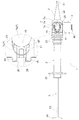
図1に、本実施形態の眼内レンズ用インジェクタ1(以下、インジェクタ1と表記する。)の全体図を示す。このインジェクタ1は、筒状の装置本体2と、装置本体2に接続される先端チップ3と、装置本体2に取付可能なレンズホルダ4と、装置本体2に内挿される棒状のプランジャ5とを有する。眼内レンズ7は、水晶体の代わりとなるレンズ部7aと、レンズ部7aから曲線状に延出した一対の前方支持部7b及び後方支持部7cとからなり、レンズホルダ4に保持される。なお、本実施形態では、レンズ部7aと一対の支持部7b、7cを有する3ピース型の眼内レンズ7を一例として示す。
プランジャ5の軸芯方向を前後方向、軸芯に垂直な方向を上下、左右方向として、適宜説明する。
1. Overall Configuration FIG. 1 shows an overall view of an intraocular lens injector 1 (hereinafter referred to as an injector 1) according to this embodiment. The
The axial center direction of the
2.装置本体
装置本体2は、前方に先端チップ3及びレンズホルダ4が係合される受部21と、前端の外面に術者が把持可能な複数の環状突起部22と、後端の外面に術者が指を掛けて保持する鍔状の保持部23とを有する。装置本体2は、耐衝撃性のあるポリカーボネートなどの樹脂を用いて形成される。
なお、環状突起部22と保持部23とは、必要とされる機能を発揮できるものであればどのような形状であっても良い。例えば、保持部23を鍔状ではなく指を掛けることができる突起などで構成しても良い。
2. Device Main Body The device
The
術者は、片方の手でプランジャ5を押込みながら、もう片方の手で環状突起部22を回動操作し、眼内レンズ7を前方支持部7b、レンズ部7a、後方支持部7cの順番で、患者の眼内に放出する。環状突起部22を設けることで、術者がインジェクタ1を把持し易くなり、インジェクタ1の操作性を高めることができる。
The surgeon rotates the
3.先端チップ
図2及び図3には、先端チップ3の平面図及び斜視図が示される。先端チップ3は、眼内レンズ7が放出される放出部31と、後方に行くに従い内径が徐々に大きくなるテーパー部32と、中央が開口された矩形の外周を有する矩形部33とを有している。矩形部33を装置本体2の受部21に係合させることで、先端チップ3は装置本体2に接続される。なお、先端チップ3と装置本体2との係合は、例えば、係止爪と係止穴とによるものなど、どのような構成であっても良い。先端チップ3は、耐薬品性や柔軟性のあるポリアミドなどの樹脂を用いて形成される。
3. Tip Tip FIGS. 2 and 3 show a plan view and a perspective view of the
眼内レンズ7は、プランジャ5に押込まれてテーパー部32の内部を通過しながら折り畳まれる。次いで、レンズ部7aの両端が折り畳まれた状態で、眼内レンズ7が放出部31に到達する。放出部31に到達した眼内レンズ7は、まず前方支持部7bが眼内に入り、次いでレンズ部7aが放出部31のカットされている側から眼内に入る。最後に、後方支持部7cが曲線形状を保ったまま眼内に入り、レンズ部7aが支持される。
The
矩形部33は、レンズホルダ4の後方突起45と係合する後方凹部35と、レンズホルダ4の係止爪49と係合する係合穴部39と、前方にはヒアルロン酸ナトリウムなどの弾粘性物質を注射器で注入可能な注入穴部36及びその周囲に注入凹部37と、を有する。
The
インジェクタ1の使用時には、レンズホルダ4が矩形部33の開口に挿入される。この時、先端チップ3の矩形部33の前後は非対称形状となっているので、術者は、レンズホルダ4の設置方向を間違えることなく、挿入することができる。また、注射器の注射針を注入穴部36へ挿入する際、注射針の先端が注入凹部37によって誘導されるので、確実に粘弾性物質の注入ができる。
When the
4.プランジャ
図4には、プランジャ5の斜視図が示される。プランジャ5は、眼内レンズ7のレンズ部7aと当接する面が平坦形状の先端部51と、装置本体2の後端で係止される係止部52と、後方に外側に突出したストッパ53と、ストッパ53の後方に鍔状の押圧部54とを有する。プランジャ5は、耐衝撃性のあるポリカーボネートなどの樹脂を用いて形成される。
なお、先端部51とストッパ53と押圧部54とは、必要とされる機能を発揮できるものであればどのような形状であっても良い。例えば、先端部51のレンズ部7aと当接する面に、レンズ部7aを挟持する突起などを設けても良い。
4). Plunger FIG. 4 shows a perspective view of the
The
プランジャ5は、装置本体2の後方から挿入され、係止部52が装置本体2の後端で係止されることによって、レンズホルダ4の切欠部46に先端部51が入る位置となるよう押込み前の初期位置が設定される。
The
また、プランジャ5の押込み時、眼内レンズ7が先端チップ3のテーパー部32の内部を前進するにつれて、先端チップ3の内面とレンズ部7aとの当接力が高まるよう構成されている。このため、プランジャ5の前進スピードが緩まるので、眼内レンズ7が勢いよく外部に放出されるのが防止される。なお、係止部52より先端部51側のプランジャ5の外周面と装置本体2の内周面との間に沿ってバネなどの弾性部材(不図示)を設けても良い。これにより、プランジャ5の押込み時に弾性部材から反力を受け、眼内レンズ7がプランジャ5の先端部51から勢いよく飛び出すことを防止できる。この弾性部材の位置は特に限定されず、例えばプランジャ5の押圧部54と装置本体2の後端との間に配置しても良く、プランジャ5の押込み時に弾性部材から反力を受ける構成であれば良い。
Further, when the
一方、眼内レンズ7が外部に放出されれば、眼内レンズ7の弾性力が開放されるので、プランジャ5が前方に急激に進み易くなる。しかしながら、本実施形態では、ストッパ53を装置本体2の後端で停止させるよう大きく突出させ、図10に示すように、押切り完了位置でプランジャ5の移動を阻止する構成としている。このため、術者の押圧力調整を必要とせず、眼内レンズ7の弾性力が開放された後にプランジャ5が一気に前進して、眼内組織に先端部51が接触することを確実に防止することができる。さらに、ストッパ53を目視してプランジャ5の押切り位置を確認することができるので、プランジャ5の先端部51の位置を確認しながら操作する必要がない。
On the other hand, if the
ストッパ53は、装置本体2の保持部23とプランジャ5の押圧部54とを、以下に示すように所定の間隔に設定する。眼内に眼内レンズ7を挿入する際、先端チップ3の内面とレンズ部7aとの当接力が高まるので、押込み操作の後半では比較的大きな押圧力を必要とする。また、眼内レンズ7は、前方支持部7b、レンズ部7a、後方支持部7cの順番で徐々に変性させながら眼内へ挿入されていくので、プランジャ5の押圧力が高まる。すなわち、眼内レンズ7を放出する時が、最も術者の押圧負担が大きいものとなる。
The
術者は、例えば、装置本体2の保持部23に人差し指と中指とを掛け、プランジャ5の押圧部54を親指で押さえることによって眼内レンズ7を放出させる。この時、装置本体2の保持部23とプランジャ5の押圧部54との間隔を、術者が最も押圧力を発揮できる所定の間隔に設定することで、術者の押圧負担を軽減できる。
通常の手の大きさの人間が、人差し指と中指との第2関節を支点としてプランジャ5を押込み操作できる距離は、0〜100mmの範囲である。このため、プランジャ5を押切った時の保持部23と押圧部54との間隔は、押込み負担を軽減できる10〜50mmの範囲が好ましい。また、プランジャ5を押切った時の保持部23と押圧部54との間隔を10mm〜30mmの範囲とすれば、慎重なプランジャ5の操作が求められる眼内レンズ7の放出時に、最も良好に押圧力を発揮することができる。
For example, the surgeon puts the index finger and the middle finger on the holding
The distance that a human with a normal hand size can push the
5.レンズホルダ
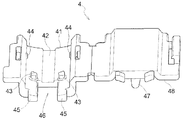
図5及び図6には、レンズホルダ4の斜視図及び側面図が示される。レンズホルダ4は、眼内レンズ7を載置する底部41と、底部41と接続され開閉自在な蓋部48とで構成される。底部41に眼内レンズ7を設置した後、蓋部48を閉めることで、眼内レンズ7を保持する。レンズホルダ4は、耐薬品性のあるポリプロピレンなどの樹脂を用いて形成される。
5. Lens Holder FIGS. 5 and 6 are a perspective view and a side view of the
レンズホルダ4の底部41は、中央の前後に亘って溝部42と、溝部42の後方の左右に突起部43(位置規制部の一例)と、側方から突出した側方突起44と、先端チップ3の後方凹部35と係合する後方突起45と、後端の中央を切欠いた切欠部46とを有する。さらに、底部41と対向するレンズホルダ4の外面には、先端チップ3の係合穴部39に係合される係止爪49を有する。なお、先端チップ3に係合穴部39を設けず、レンズホルダ4の係止爪49を装置本体2の受部21に係合させる構成としても良い。
また、突起部43や切欠部46などは、必要とされる機能を発揮できるものであればどのような形状であっても良い。例えば、突起部43から後方が全て開口した切欠部46を有する形状としても良い。
The bottom 41 of the
Further, the
眼内レンズ7のレンズ部7aと後方支持部7cとの間には突起部43が配置され、後方支持部7cをレンズ部7aから離間させた状態で眼内レンズ7はレンズホルダ4に保持される。この時、図1に示すように後方支持部7cが後端の中央を切欠いた切欠部46を横断した状態となる。また、前方支持部7bが側方突起44と当接することで、眼内レンズ7の回転が規制される。このように、突起部43と側方突起44とによって、眼内レンズ7はレンズホルダ4の一定位置に保持される。このため、インジェクタ1の運搬時や予期せぬ外力によって、眼内レンズ7の位置がずれ難い構成となっている。
なお、突起部43におけるレンズ部7aとの当接面は、レンズ部7aの周縁部の曲率と同じ曲率を持たせると好適である。これにより、レンズ部7aと突起部43とが、レンズ部7aの周方向に沿って所定の距離だけ当接することが可能となり、より安定した保持が可能となる。
A
It is preferable that the contact surface of the
後方支持部7cが切欠部46を横断して保持されているので、レンズホルダ4を装置本体2に上方から組み付ける際、後方支持部7cはプランジャ5の先端部51の上に乗った状態となる。すなわち、切欠部46によって、押込み前の初期位置にあるプランジャ5の先端部51が、眼内レンズ7と同一平面状の位置まで受け入られた状態となる。
また、切欠部46以外の部位によって後方支持部7cを支持することが可能となり、レンズホルダ4を装置本体2に組付ける際に、後方支持部7cを確実にプランジャ5の先端部51に載置することができる。このように、レンズホルダ4の底部41に切欠部46を設けることで、後方支持部7cを安定的に支持することができる。
さらに、レンズホルダ4を装置本体2に上方から組み付ける際、突起部43によって後方支持部7cをレンズ部7aから離間させているので、後方支持部7cがプランジャ5の上に確実に載置される。
このため、プランジャ5の押込みを開始した時、プランジャ5の先端部51が当接して、後方支持部7cが思わぬ方向に変形したり破損したりしてしまうことを防止できる。
Since the
Further, it becomes possible to support the
Furthermore, when the
For this reason, when pushing-in of the
インジェクタ1の初期設定が完了した後、プランジャ5の先端部51をレンズ部7aに当接させつつ溝部42に沿って押込むと、プランジャ5の上に乗った後方支持部7cは突起部43を乗越え、曲線形状を維持したまま円滑に前進する。この時、プランジャ5は、溝部42に沿って前進方向が一定に保たれる。
また、蓋部48の外面の外側に突出して把持部47が形成されている。眼内レンズ7を設置するためにレンズホルダ4の蓋部48を開閉する際、把持部47を掴んで操作することができるので、操作性に優れる。
なお、レンズホルダ4が装置本体2に予め設置されたインジェクタ1に、眼内レンズ7を設置してもよいし、把持部47を設けてなくてもよい。装置本体2に設置されたレンズホルダ4に眼内レンズ7を設置する場合、図7に示すように突起部43がレンズ部7aと後方支持部7cとの間に配置するように、鑷子などを用いて眼内レンズ7をレンズホルダ4に設置すればよいので、利便性が高い。
After the initial setting of the
Further, a
In addition, the
6.組立て手順
図7〜図9を用いてインジェクタ1の組立て手順を説明する。
6). Assembling Procedure The assembling procedure of the
まず、先端チップ3を装置本体2の上から挿入して係合させる。次いで、プランジャ5を装置本体2の後端から挿入する。この時、図8に示すようにプランジャ5の係止部52が装置本体2の後端で係止されることによって、レンズホルダ4の切欠部46にプランジャ5の先端部51が入るよう位置決めされる。このため、プランジャ5と先端チップ3とは、搬送時に装置本体2から位置ずれするおそれが少ない。
First, the
続いて、図7を用いて、レンズホルダ4について説明する。まず、眼内レンズ7をレンズホルダ4の底部41に設置する。この時、レンズ部7aの患者の眼に向けられる裏側の面を下にして、レンズ部7aの周縁部が突起部43と当接するように載置する。これにより、後方支持部7cは突起部43を跨いで後方に位置し、切欠部46の上に横断した状態となる。同時に、前方支持部7bは側方突起44と当接して、眼内レンズ7がレンズホルダ4の所定位置に保持される。この状態で、蓋部48を被せて、滅菌水で満たされた図示しないホルダ収容容器に入れ、密閉状態とされる。この時、眼内レンズ7は突起部43と側方突起44とで移動が規制されているので、搬送時に位置ずれするおそれが少ない。
また、レンズホルダ4のみを滅菌水の入った容器に保管すれば済むので、インジェクタ1の内部に眼内レンズ7を予めセットして保管する場合に比べ、術者は液体で濡れた容器を触る抵抗感が小さい。
Subsequently, the
Further, since only the
続いて、図8を用いて、術者によるインジェクタ1の設定方法について説明する。まず、工場で組付けられた装置本体2などを図示しない容器から取り出す。この時、術者はプランジャ5の先端部51が装置本体2の前端から出ていることを目視で確認する。装置本体2の前方は上方に開放されているので、術者は、押込み前の初期位置にあるプランジャ5の先端部51の位置を容易に確認することができる。
次いで、レンズホルダ4を図示しないホルダ収容容器から取り出して、装置本体2の上から、すなわち、プランジャ5の軸芯方向に対して交差する方向からレンズホルダ4を装置本体2に組み付ける。これによって、図1に示すように眼内レンズ7の後方支持部7cは、確実にプランジャ5の先端部51の上に乗った状態となる。このため、術者の熟練度に拘らず、簡単に組立てが可能となる。次いで、先端チップ3の注入穴部36から弾粘性物質を注入すると、図9に示すようにプランジャ5は押込み操作可能な初期状態に設定される。
Then, the setting method of the
Next, the
装置本体2に設置されたレンズホルダ4に眼内レンズ7を設置する場合は、まず、装置本体2の上から、すなわち、プランジャ5の軸芯方向に対して交差する方向からレンズホルダ4を装置本体2に組み付ける。この組み付けは、工場組立段階でも良いし、使用時でも良い。使用時において、術者はプランジャ5の先端部51が装置本体2の前端から出ていることを目視で確認する。次いで、眼内レンズ7を図示しないレンズ収容容器から取り出して、突起部43がレンズ部7aと後方支持部7cとの間に配置するように、鑷子などを用いてレンズホルダ4に設置する。これによって、図1に示すように眼内レンズ7の後方支持部7cは、確実にプランジャ5の先端部51の上に乗った状態となるので利便性が高い。次いで、先端チップ3の注入穴部36から弾粘性物質を注入すると、図9に示すようにプランジャ5は押込み操作可能な初期状態に設定される。
When the
7.操作手順
図10は、押切り完了位置を示す模式図である。
図9に示すようにインジェクタ1を初期状態に設定した後、術者はプランジャ5の押込み作業を開始する。この時、術者は、先端チップ3の放出部31が眼内組織に接触しないように、患者から離れた位置でプランジャ5を押込み操作する。次いで、術者は、プランジャ5のストッパ53を目視しつつプランジャ5の押込み状況を確認してから、ある程度押込み操作が進んだ時点で放出部31を患者の眼に挿入する。次いで、図10に示すプランジャ5の先端部51が放出部31から出る直前の状態において、インジェクタ1をゆっくりと回動させながら放出部31のカットしている側を眼の奥側に向け、眼内レンズ7を眼内に放出する。
7). Operation Procedure FIG. 10 is a schematic diagram showing a press-cut completion position.
After setting the
[別実施形態]
(1)図11に示すように、プランジャ5のストッパ55は、押圧部54まで連なった円柱形状としてもよい。これにより、当該円柱形状に係る部位のプランジャ5の剛性が高まり、押込み方向の強い押圧に際して変形が抑制されるので、眼内レンズ7の押込み操作が安定したものとなる。
(2)その他、プランジャ5のストッパ55を、例えば鍔形状や扁平形状にするなど、プランジャ5の前進を阻止できるものであれば、種々の変形が可能である。
(3)レンズホルダ4の位置規制部は、例えば、突起部43の上面に眼内レンズ7の後方支持部7cを収容可能な凹部を設けてもよい。これにより、後方支持部7cの安定性を高めることができるので、インジェクタ1の搬送時において眼内レンズ7の移動をより抑制することができる。
(4)その他、レンズホルダ4の位置規制部は、後方支持部7cがレンズホルダ4の切欠部46を横断する状態となり、かつ、眼内レンズ7の保管に適した構造であれば、種々の変形が可能である。
(5)レンズホルダ4に設けた側方突起44と眼内レンズ7の前方支持部7bとが当接することで、搬送時などの位置ずれを防止すべく眼内レンズ7の移動を規制する構成にしたが、側方突起44を設けなくても良い。この場合でも、突起部43が後方支持部7cとレンズ部7aとの間に位置しているので、眼内レンズ7の移動が規制される。
(6)図12に示すように、レンズホルダ4の蓋部48の前方に穴を設け、この穴に規制ピン60を挿入しても良い。その結果、規制ピン60は、レンズホルダ4に保持された眼内レンズ7の前方支持部7bとレンズ部7aとの間に位置することとなり、眼内レンズ7の移動が規制される。この場合、プランジャ5の押込み操作は、規制ピン60を取り除いてから実行されるので、プランジャ5の押込み操作によって眼内レンズ7を円滑に進めることができる。
[Another embodiment]
(1) As shown in FIG. 11, the
(2) In addition, various modifications are possible as long as the
(3) The position restricting portion of the
(4) In addition, the position restricting portion of the
(5) A configuration in which the movement of the
(6) As shown in FIG. 12, a hole may be provided in front of the
本発明は、眼内レンズを眼内に挿入するための眼内レンズ用インジェクタに利用可能である。 The present invention is applicable to an intraocular lens injector for inserting an intraocular lens into the eye.
1 眼内レンズ用インジェクタ
2 装置本体
23 保持部
4 レンズホルダ
41 底部
43 突起部(位置規制部)
46 切欠部
5 プランジャ
51 先端部
53 ストッパ
54 押圧部
7 眼内レンズ
7a レンズ部
7b 前方支持部(支持部)
7c 後方支持部(支持部)
DESCRIPTION OF
46
7c Rear support part (support part)
Claims (5)
当該眼内レンズに当接して前記眼内レンズを押し出すプランジャと、
当該プランジャを出退可能に内挿すると共に、前記レンズホルダを前記プランジャの軸芯方向に対して交差する方向から取付可能な装置本体と、を備え、
前記レンズホルダは、押込み前の初期位置にある前記プランジャの先端部と前記レンズ部とが同一平面上の配置で、前記支持部の一部が前記プランジャに乗った状態となるよう、前記支持部の設置位置を規制する位置規制部を備えている眼内レンズ用インジェクタ。 A lens holder for holding an intraocular lens having a lens part and a support part extending in a curved shape from the lens part;
A plunger that contacts the intraocular lens and pushes out the intraocular lens;
An apparatus main body capable of inserting the plunger so as to be retractable and attaching the lens holder from a direction intersecting the axial center direction of the plunger,
The lens holder is configured so that the distal end portion of the plunger and the lens portion at the initial position before being pushed are arranged on the same plane, and the support portion is in a state of being on the plunger. An intraocular lens injector comprising a position restricting portion for restricting the installation position of the lens.
当該押圧部とは異なる位置に、前記装置本体の前記レンズホルダとは反対側の端面に当接して前記プランジャの押込み方向の移動を阻止するストッパを設けた請求項1〜3のいずれか一項に記載の眼内レンズ用インジェクタ。 The plunger includes a pressing portion that applies a pressing force at the rear end,
The stopper which contacts the end surface on the opposite side to the said lens holder of the said apparatus main body at the position different from the said press part, and prevents the movement of the said plunger in the pushing direction is provided. An injector for an intraocular lens as described in 1.
前記ストッパは、前記保持部と前記押圧部との間隔を所定の間隔に設定する請求項4に記載の眼内レンズ用インジェクタ。 The apparatus main body includes a holding portion protruding outward on the outer surface of the end opposite to the lens holder,
The intraocular lens injector according to claim 4, wherein the stopper sets an interval between the holding portion and the pressing portion to a predetermined interval.
Priority Applications (1)
| Application Number | Priority Date | Filing Date | Title |
|---|---|---|---|
| JP2013223267A JP6379421B2 (en) | 2012-10-26 | 2013-10-28 | Intraocular lens injector |
Applications Claiming Priority (3)
| Application Number | Priority Date | Filing Date | Title |
|---|---|---|---|
| JP2012237001 | 2012-10-26 | ||
| JP2012237001 | 2012-10-26 | ||
| JP2013223267A JP6379421B2 (en) | 2012-10-26 | 2013-10-28 | Intraocular lens injector |
Publications (2)
| Publication Number | Publication Date |
|---|---|
| JP2014100558A true JP2014100558A (en) | 2014-06-05 |
| JP6379421B2 JP6379421B2 (en) | 2018-08-29 |
Family
ID=50544796
Family Applications (1)
| Application Number | Title | Priority Date | Filing Date |
|---|---|---|---|
| JP2013223267A Active JP6379421B2 (en) | 2012-10-26 | 2013-10-28 | Intraocular lens injector |
Country Status (7)
| Country | Link |
|---|---|
| US (1) | US9827139B2 (en) |
| EP (1) | EP2913029A4 (en) |
| JP (1) | JP6379421B2 (en) |
| KR (1) | KR102212198B1 (en) |
| CN (1) | CN104755045B (en) |
| TW (1) | TWI608852B (en) |
| WO (1) | WO2014065426A1 (en) |
Cited By (3)
| Publication number | Priority date | Publication date | Assignee | Title |
|---|---|---|---|---|
| WO2016017772A1 (en) * | 2014-07-30 | 2016-02-04 | 興和株式会社 | Intraocular lens insertion instrument |
| US9757536B2 (en) | 2012-07-17 | 2017-09-12 | Novartis Ag | Soft tip cannula |
| WO2018116992A1 (en) | 2016-12-19 | 2018-06-28 | 参天製薬株式会社 | Intraocular lens injector |
Families Citing this family (12)
| Publication number | Priority date | Publication date | Assignee | Title |
|---|---|---|---|---|
| US9463089B2 (en) | 2012-05-21 | 2016-10-11 | Novartis Ag | Plunger system for intraocular lens surgery |
| JP6511065B2 (en) * | 2013-11-15 | 2019-05-15 | メディセル・アーゲー | Device for receiving an intraocular lens and method of folding an intraocular lens |
| KR20170072224A (en) * | 2014-10-22 | 2017-06-26 | 산텐 세이야꾸 가부시키가이샤 | Intraocular lens injector |
| US10588780B2 (en) | 2015-03-04 | 2020-03-17 | Alcon Inc. | Intraocular lens injector |
| AU2016354549B2 (en) * | 2015-11-13 | 2020-11-26 | Johnson & Johnson Surgical Vision, Inc. | Intraocular lens insertion device |
| BE1024131B1 (en) * | 2016-04-21 | 2017-11-20 | Physiol S.A. | Soft intraocular lens injection device and storage shuttle for its implementation |
| CN107595434A (en) * | 2016-07-11 | 2018-01-19 | 上海中医药大学附属龙华医院 | Integral type artificial lens injector |
| US10568735B2 (en) | 2017-01-13 | 2020-02-25 | Alcon Inc. | Intraocular lens injector |
| US11000367B2 (en) | 2017-01-13 | 2021-05-11 | Alcon Inc. | Intraocular lens injector |
| CN108852558B (en) * | 2018-05-10 | 2021-01-15 | 辽宁美滋林药业有限公司 | Intraocular lens injection device |
| BR112021009184A2 (en) * | 2018-12-13 | 2021-08-17 | Alcon Inc. | haptic optical management system using rotating cams |
| CN112515815B (en) * | 2019-09-17 | 2023-12-26 | 富螺(上海)医疗器械有限公司 | Intraocular lens injector and intraocular lens implantation method |
Citations (12)
| Publication number | Priority date | Publication date | Assignee | Title |
|---|---|---|---|---|
| JP2004351196A (en) * | 2003-05-28 | 2004-12-16 | Alcon Inc | Lens delivery system |
| JP2005515807A (en) * | 2001-12-12 | 2005-06-02 | イオルテクノロジー−プロダクション | Cassette and injector for flexible intraocular lens and lens insertion method |
| WO2005070341A1 (en) * | 2004-01-27 | 2005-08-04 | Hoya Corporation | Intraocular lens inserting device and cartridge thereof |
| US20060200167A1 (en) * | 2005-03-02 | 2006-09-07 | Peterson Rod T | Devices and methods for storing, loading, and delivering an intraocular lens |
| WO2007080869A1 (en) * | 2006-01-13 | 2007-07-19 | Hoya Corporation | Instrument for inserting intraocular lens |
| JP2007307082A (en) * | 2006-05-17 | 2007-11-29 | Canon Star Kk | Intraocular lens insertion apparatus |
| JP2008012016A (en) * | 2006-07-05 | 2008-01-24 | Hoya Corp | Intraocular lens insertion appliance |
| JP2008061677A (en) * | 2006-09-05 | 2008-03-21 | Kowa Co | Inserting device for intraocular lens |
| JP2009160138A (en) * | 2007-12-28 | 2009-07-23 | Menicon Co Ltd | Intraocular lens insertion tool |
| JP2010273986A (en) * | 2009-05-29 | 2010-12-09 | Nidek Co Ltd | Intraocular lens inserter |
| JP2011004979A (en) * | 2009-06-25 | 2011-01-13 | Staar Japan Kk | Intraocular lens insertion instrument, built-in type intraocular lens insertion instrument, and method for manufacturing built-in type intraocular lens insertion instrument |
| JP2011045712A (en) * | 2009-08-18 | 2011-03-10 | Carl Zeiss Meditec Sas | Cassette for receiving intraocular lens, lens injector device and method for advancing intraocular lens out of cassette |
Family Cites Families (3)
| Publication number | Priority date | Publication date | Assignee | Title |
|---|---|---|---|---|
| JP2004041271A (en) * | 2002-07-09 | 2004-02-12 | Menicon Co Ltd | Intraocular lens inserting instrument |
| JP4648859B2 (en) * | 2006-03-15 | 2011-03-09 | スター・ジャパン株式会社 | Intraocular lens insertion device and intraocular lens insertion system |
| JP5627861B2 (en) | 2009-05-29 | 2014-11-19 | 株式会社ニデック | Intraocular lens insertion device |
-
2013
- 2013-10-28 US US14/437,577 patent/US9827139B2/en not_active Expired - Fee Related
- 2013-10-28 KR KR1020157010949A patent/KR102212198B1/en active IP Right Grant
- 2013-10-28 EP EP13849553.6A patent/EP2913029A4/en not_active Withdrawn
- 2013-10-28 CN CN201380055741.3A patent/CN104755045B/en not_active Expired - Fee Related
- 2013-10-28 JP JP2013223267A patent/JP6379421B2/en active Active
- 2013-10-28 WO PCT/JP2013/079079 patent/WO2014065426A1/en active Application Filing
- 2013-10-28 TW TW102138904A patent/TWI608852B/en active
Patent Citations (12)
| Publication number | Priority date | Publication date | Assignee | Title |
|---|---|---|---|---|
| JP2005515807A (en) * | 2001-12-12 | 2005-06-02 | イオルテクノロジー−プロダクション | Cassette and injector for flexible intraocular lens and lens insertion method |
| JP2004351196A (en) * | 2003-05-28 | 2004-12-16 | Alcon Inc | Lens delivery system |
| WO2005070341A1 (en) * | 2004-01-27 | 2005-08-04 | Hoya Corporation | Intraocular lens inserting device and cartridge thereof |
| US20060200167A1 (en) * | 2005-03-02 | 2006-09-07 | Peterson Rod T | Devices and methods for storing, loading, and delivering an intraocular lens |
| WO2007080869A1 (en) * | 2006-01-13 | 2007-07-19 | Hoya Corporation | Instrument for inserting intraocular lens |
| JP2007307082A (en) * | 2006-05-17 | 2007-11-29 | Canon Star Kk | Intraocular lens insertion apparatus |
| JP2008012016A (en) * | 2006-07-05 | 2008-01-24 | Hoya Corp | Intraocular lens insertion appliance |
| JP2008061677A (en) * | 2006-09-05 | 2008-03-21 | Kowa Co | Inserting device for intraocular lens |
| JP2009160138A (en) * | 2007-12-28 | 2009-07-23 | Menicon Co Ltd | Intraocular lens insertion tool |
| JP2010273986A (en) * | 2009-05-29 | 2010-12-09 | Nidek Co Ltd | Intraocular lens inserter |
| JP2011004979A (en) * | 2009-06-25 | 2011-01-13 | Staar Japan Kk | Intraocular lens insertion instrument, built-in type intraocular lens insertion instrument, and method for manufacturing built-in type intraocular lens insertion instrument |
| JP2011045712A (en) * | 2009-08-18 | 2011-03-10 | Carl Zeiss Meditec Sas | Cassette for receiving intraocular lens, lens injector device and method for advancing intraocular lens out of cassette |
Cited By (7)
| Publication number | Priority date | Publication date | Assignee | Title |
|---|---|---|---|---|
| US9757536B2 (en) | 2012-07-17 | 2017-09-12 | Novartis Ag | Soft tip cannula |
| WO2016017772A1 (en) * | 2014-07-30 | 2016-02-04 | 興和株式会社 | Intraocular lens insertion instrument |
| JPWO2016017772A1 (en) * | 2014-07-30 | 2017-05-18 | 興和株式会社 | Intraocular lens insertion device |
| JP7066320B2 (en) | 2014-07-30 | 2022-05-13 | 興和株式会社 | Intraocular lens insertion device |
| WO2018116992A1 (en) | 2016-12-19 | 2018-06-28 | 参天製薬株式会社 | Intraocular lens injector |
| JP2022111289A (en) * | 2016-12-19 | 2022-07-29 | 参天製薬株式会社 | Injector for intraocular lens |
| JP7339397B2 (en) | 2016-12-19 | 2023-09-05 | 参天製薬株式会社 | intraocular lens injector |
Also Published As
| Publication number | Publication date |
|---|---|
| US9827139B2 (en) | 2017-11-28 |
| KR20150080500A (en) | 2015-07-09 |
| JP6379421B2 (en) | 2018-08-29 |
| TW201431576A (en) | 2014-08-16 |
| US20150272779A1 (en) | 2015-10-01 |
| EP2913029A4 (en) | 2016-06-15 |
| KR102212198B1 (en) | 2021-02-03 |
| WO2014065426A1 (en) | 2014-05-01 |
| CN104755045A (en) | 2015-07-01 |
| TWI608852B (en) | 2017-12-21 |
| CN104755045B (en) | 2017-11-24 |
| EP2913029A1 (en) | 2015-09-02 |
Similar Documents
| Publication | Publication Date | Title |
|---|---|---|
| JP6379421B2 (en) | Intraocular lens injector | |
| JP6278701B2 (en) | Intraocular lens injector | |
| US10039668B2 (en) | Ocular implant insertion apparatus and methods | |
| EP2298242B1 (en) | Assembly for use with a intraocular lens | |
| US8470032B2 (en) | Intraocular lens insertion device | |
| JP5470753B2 (en) | Intraocular lens insertion device | |
| WO2015012312A1 (en) | Intraocular lens-inserting instrument | |
| WO2006070561A1 (en) | Instrument for inserting intraocular lens | |
| WO2016195095A1 (en) | Intraocular lens insertion tool | |
| US20110144654A1 (en) | System and Method for Storing, Shipping and Injecting Ocular Devices | |
| KR20150035982A (en) | Intraocular lens insertion tool, and positioning member provided in intraocular lens insertion tool | |
| JP6057749B2 (en) | Intraocular lens insertion device | |
| JP6027536B2 (en) | Intraocular lens insertion device | |
| JP6524588B2 (en) | Intraocular lens insertion device | |
| JP6669346B2 (en) | Intraocular lens insertion device | |
| JP6601945B2 (en) | Intraocular lens insertion device |
Legal Events
| Date | Code | Title | Description |
|---|---|---|---|
| A621 | Written request for application examination |
Free format text: JAPANESE INTERMEDIATE CODE: A621 Effective date: 20160823 |
|
| A977 | Report on retrieval |
Free format text: JAPANESE INTERMEDIATE CODE: A971007 Effective date: 20170614 |
|
| A131 | Notification of reasons for refusal |
Free format text: JAPANESE INTERMEDIATE CODE: A131 Effective date: 20170620 |
|
| A521 | Request for written amendment filed |
Free format text: JAPANESE INTERMEDIATE CODE: A523 Effective date: 20170818 |
|
| A131 | Notification of reasons for refusal |
Free format text: JAPANESE INTERMEDIATE CODE: A131 Effective date: 20171219 |
|
| A521 | Request for written amendment filed |
Free format text: JAPANESE INTERMEDIATE CODE: A523 Effective date: 20180202 |
|
| TRDD | Decision of grant or rejection written | ||
| A01 | Written decision to grant a patent or to grant a registration (utility model) |
Free format text: JAPANESE INTERMEDIATE CODE: A01 Effective date: 20180703 |
|
| A61 | First payment of annual fees (during grant procedure) |
Free format text: JAPANESE INTERMEDIATE CODE: A61 Effective date: 20180712 |
|
| R150 | Certificate of patent or registration of utility model |
Ref document number: 6379421 Country of ref document: JP Free format text: JAPANESE INTERMEDIATE CODE: R150 |
|
| R250 | Receipt of annual fees |
Free format text: JAPANESE INTERMEDIATE CODE: R250 |
|
| R250 | Receipt of annual fees |
Free format text: JAPANESE INTERMEDIATE CODE: R250 |
|
| R250 | Receipt of annual fees |
Free format text: JAPANESE INTERMEDIATE CODE: R250 |