JP2014064893A - Dental suction tube - Google Patents
Dental suction tube Download PDFInfo
- Publication number
- JP2014064893A JP2014064893A JP2013163803A JP2013163803A JP2014064893A JP 2014064893 A JP2014064893 A JP 2014064893A JP 2013163803 A JP2013163803 A JP 2013163803A JP 2013163803 A JP2013163803 A JP 2013163803A JP 2014064893 A JP2014064893 A JP 2014064893A
- Authority
- JP
- Japan
- Prior art keywords
- distal portion
- dental suction
- holes
- distal
- longitudinal axis
- Prior art date
- Legal status (The legal status is an assumption and is not a legal conclusion. Google has not performed a legal analysis and makes no representation as to the accuracy of the status listed.)
- Pending
Links
Images


Classifications
-
- A—HUMAN NECESSITIES
- A61—MEDICAL OR VETERINARY SCIENCE; HYGIENE
- A61C—DENTISTRY; APPARATUS OR METHODS FOR ORAL OR DENTAL HYGIENE
- A61C17/00—Devices for cleaning, polishing, rinsing or drying teeth, teeth cavities or prostheses; Saliva removers; Dental appliances for receiving spittle
- A61C17/06—Saliva removers; Accessories therefor
- A61C17/08—Aspiration nozzles
-
- F—MECHANICAL ENGINEERING; LIGHTING; HEATING; WEAPONS; BLASTING
- F04—POSITIVE - DISPLACEMENT MACHINES FOR LIQUIDS; PUMPS FOR LIQUIDS OR ELASTIC FLUIDS
- F04C—ROTARY-PISTON, OR OSCILLATING-PISTON, POSITIVE-DISPLACEMENT MACHINES FOR LIQUIDS; ROTARY-PISTON, OR OSCILLATING-PISTON, POSITIVE-DISPLACEMENT PUMPS
- F04C2270/00—Control; Monitoring or safety arrangements
- F04C2270/04—Force
- F04C2270/042—Force radial
- F04C2270/0421—Controlled or regulated
Abstract
Description
本発明は、概して、歯科吸引管に関し、より具体的には、治療中に歯科患者の口腔から流体及び固体を吸引するための装置に関する。 The present invention relates generally to dental aspiration tubes, and more specifically to an apparatus for aspirating fluids and solids from a dental patient's oral cavity during treatment.
歯科においては、口腔の視野を確保し、口腔の作業エリアを水、唾液その他の物質から乾いた状態に維持することが、非常に重要である。また、患者の舌や頬を作業エリアをから遠ざけておくことも、重要である。 In dentistry, it is very important to ensure the visual field of the oral cavity and keep the oral work area dry from water, saliva and other substances. It is also important to keep the patient's tongue and cheeks away from the work area.
これらの目的は、従来、種々の事項の組み合わせによって達成されている。歯鏡は、舌、頬その他の組織を邪魔にならない所に固定するために使用され得る。また、エアウォーターシリンジは、空気及び水を口腔内及び歯鏡上に吹き付け、口腔及び歯鏡を清潔に維持するために使用され得る。エアウォーターシリンジは、コントローラに固定された小さな金属管であり、少なくとも一時的に、舌、頬その他の組織を邪魔にならない所に固定するのに十分な剛性を有する。さらに、歯科吸引管が、使用されることもある。歯科吸引管は、口腔から流体及び固体の物質を除去し、治療中に口腔を清潔、かつ障害物が無い状態に維持する。 These objects have been achieved by a combination of various items. The dental mirror can be used to secure the tongue, cheeks and other tissues in an unobstructed place. Air water syringes can also be used to spray air and water into the oral cavity and on the dental mirror to keep the oral cavity and dental mirror clean. An air water syringe is a small metal tube that is secured to a controller and is sufficiently rigid to at least temporarily secure the tongue, cheeks, and other tissues out of the way. In addition, a dental suction tube may be used. The dental suction tube removes fluids and solid substances from the oral cavity and keeps the oral cavity clean and free of obstructions during treatment.
しかしながら、これら3つの器具全てを同時に使用することは通常、現実的ではなく、仮に実施可能な場合であっても、3つの器具の使用は、非常に煩わしい。また、現在市販されている高速な歯科管を使用する場合、そのような歯科管は、正面にのみ通気口を備えており、それが舌や頬によって覆われると、吸引は停止し、非効率なものとなる。また、現在の吸引装置は、患者がその中に唾液を吐き出すことができないほど非常に強い吸引を行うため、余分な唾液を除去するために、高速吸引管を口腔から取り除き、低速な唾液排除器を挿入しなければならないような場合がある。この処置は、非効率なだけでなく、低速な唾液排除器は、患者の舌又は頬の動きを許容しないものでもある。なぜなら、それは、高い柔軟性を有するからである。したがって、現在市販されている器具を使用する場合、歯科医及び歯科助手は通常、3つ又は4つの器具を使用し、それらを交代で使用しながら、治療を遂行する。 However, using all three instruments at the same time is usually not practical and even if feasible, the use of the three instruments is very cumbersome. Also, when using high-speed dental tubes that are currently on the market, such dental tubes only have a vent on the front, and if it is covered by the tongue or cheek, suction stops and is inefficient It will be something. In addition, the current suction device performs suction that is so strong that the patient cannot spit saliva into it. May have to be inserted. Not only is this procedure inefficient, but a slow saliva evacuator does not allow movement of the patient's tongue or cheek. Because it has high flexibility. Thus, when using instruments that are currently on the market, dentists and dental assistants typically use three or four instruments and perform treatment while using them alternately.
本発明の一実施形態は、外側表面、内側表面、近位部、及び遠位部を有する細長い実質的に管状の部材を含む、歯科吸引装置である。近位部は、第1の長手方向軸を規定する。遠位部は、近位部から延び、第2の長手方向軸を規定する。第1の長手方向軸は、第2の長手方向軸に対して、150度から180度までの角度にある。複数の孔が、遠位部の少なくとも一部に螺旋状に設けられ、各孔は、実質的に管状の部材の外側表面から内側表面まで延びる。 One embodiment of the present invention is a dental suction device that includes an elongated substantially tubular member having an outer surface, an inner surface, a proximal portion, and a distal portion. The proximal portion defines a first longitudinal axis. The distal portion extends from the proximal portion and defines a second longitudinal axis. The first longitudinal axis is at an angle from 150 degrees to 180 degrees with respect to the second longitudinal axis. A plurality of holes are helically provided in at least a portion of the distal portion, each hole extending from the outer surface to the inner surface of the substantially tubular member.
本発明の他の実施形態は、吸引によるその中を通した物質の移動を可能とするための実質的に中空の内部を有する近位部と、前記近位部に結合され、前記近位部から遠くへ延びる遠位部とを備えた歯科吸引管である。遠位部は、吸引によるその中を通した物質の移動を可能とするための実質的に中空の内部を備えている。遠位部は、開口部を有する遠位端を規定する。複数の孔が遠位部に配置され、遠位端開口部の断面積に対する孔の合計断面積の比率は、約40%から約70%までの範囲内にある。 Another embodiment of the present invention includes a proximal portion having a substantially hollow interior for allowing movement of material therethrough by suction, coupled to the proximal portion, and the proximal portion And a distal portion extending far from the dental suction tube. The distal portion has a substantially hollow interior to allow movement of the substance therethrough by suction. The distal portion defines a distal end having an opening. A plurality of holes are disposed in the distal portion, and the ratio of the total cross-sectional area of the holes to the cross-sectional area of the distal end opening is in the range of about 40% to about 70%.
本発明のさらに別の実施形態は、実質的に管状の近位部であって、その中を通した物質の輸送のための実質的に中空の内部を規定する外装壁を有する近位部を含む、歯科吸引管である。この管は、近位部と連通する遠位部であって、その中を通した物質の輸送のための実質的に中空の内部を有する遠位部をさらに含む。遠位部は、長手全長と、開口部を備えた遠位端と、少なくとも10個の孔を備えた少なくとも1つの外装壁とを有する。孔はそれぞれ、他の孔から、遠位部の全長の約5%から約15%までの距離だけ、間隔を空けて設けられる。 Yet another embodiment of the present invention comprises a proximal portion having a substantially tubular proximal portion having an exterior wall defining a substantially hollow interior for transport of material therethrough. Including a dental suction tube. The tube further includes a distal portion in communication with the proximal portion and having a substantially hollow interior for transport of material therethrough. The distal portion has a longitudinal length, a distal end with an opening, and at least one exterior wall with at least 10 holes. Each hole is spaced from the other hole by a distance of about 5% to about 15% of the total length of the distal portion.
本発明の他の利点、課題、及び/又は目的は、下記の明細書を読み、添付の図面を検討したとき、この一般型の構成に精通する者には、明らかとなるであろう。 Other advantages, problems and / or objects of the present invention will become apparent to those familiar with this general type of construction upon reading the following specification and studying the accompanying drawings.
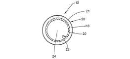
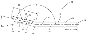
本発明の歯科吸引管10の一実施形態が、図1〜図4に示されている。図1及び図2を具体的に参照すると、歯科吸引管10は、近位部12、遠位部14、及び止め具16を含む。近位部12は、好ましくは、円筒形の形を有し、実質的に管状である。近位部12は、開口部を備えた近位端18と、外側表面21及び内側表面22を有する外壁20とを含む(図2参照)。近位部12、及び歯科吸引管全体は、実質的に中空の内部24を有し、それによって、管10に吸引が加えられたときに、その中を通した流体及び固体の輸送が可能となる。
One embodiment of a
止め具16は、近位部12の外側表面21から半径方向外向きに延びている。止め具16は、その近位側と遠位側の両方に概ね平坦な表面を有する。止め具16は、好ましくは、丸みを帯びた又は面取りされた外縁26を有する。止め具16は、好ましくは、近位端18から、管10を吸引装置に取り付けるために十分な距離だけ、遠くに設けられる。この距離は、近位端18から約25.4ミリメートル(約1インチ)である場合がある(図1及び図3参照)。止め具16が配置される近位端18からの距離は、図3にAで示されている。止め具16は、好ましくは環状であるが、近位部12の外側表面21から半径方向に延びる1以上の部材を備えた非環状の止め具を使用することも可能であると考えられる。
The
図1及び図3に示されているように、管10は、近位部12と遠位部14の接合部に、屈曲部28を有する。屈曲部28は、流体及び固体が、遠位部14の中を容易に通過し、近位部12に入り、近位部12を通過して、治療エリアから除去されることが可能となるくらいの十分な緩やかさを有する。近位部12は、第1の長手方向軸30を有し、遠位部は、第2の長手方向軸32を有する(図3参照)。第1の長手方向軸と第2の長手方向軸32の角度は、図3に文字Xで示されている。Xは、好ましくは、約150度から約180度までの間であり、より好ましくは、約160度から約170度までの間であり、最も好ましくは、約165度である。そのような角度は、発生し得る障害物を移動又は固定する際にも、作業エリアから物質の吸引をする際にも、ユーザの助けとなる。
As shown in FIGS. 1 and 3, the
管10の遠位部14は、少なくとも1つの壁34から形成され、壁34は、近位部12の壁20に結合される。したがって、遠位部14は、近位部12と連通している。遠位部14は、好ましくは、遠位開口部35を有し、及び図3にBで示すような全長を有する。
The
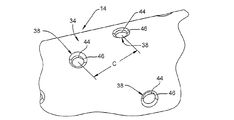
壁34は、複数の孔38を備えた外側表面36を有し、各孔38は、外側表面36から壁34を通して遠位部14の内部40まで延びる。孔38は、屈曲部38から管10の遠位部42まで概ね長手方向に延びている。好ましくは、遠位端14は、少なくとも10個の孔を有し、より好ましくは、20個より多くの孔を有し、さらにもっと好ましくは25個より多くの孔を有し、最も好ましくは、約30個の孔を有する。しかしながら、10個よりも少ない孔を使用することも可能であると考えられる。孔38は、好ましくは、遠位部の全長Bの少なくとも約5%から約15%までの距離だけ、互いに間隔を空けて設けられる。
The
また、好ましくは、孔は、円周方向、及び(長手方向軸32に関して)長手方向に、間隔を空けて設けられ、孔が遠位部14にわたって実質的に均一に間隔を空けて設けられるようになっている。より好ましくは、孔38は、長手方向軸32を中心として遠位部14に沿って螺旋状に延びる(図1及び図3参照)。孔38の螺旋は、図3に符号43で示されている仮想的な螺旋ラインに沿って延びる。ライン43と長手方向軸32の間の角度は、図3に文字Yで示されている。Yは、好ましくは、約20度から約35度までの間であり、より好ましくは、約25度から約30度までの間であり、最も好ましくは、約27.5度である。
Also preferably, the holes are spaced circumferentially and longitudinally (with respect to the longitudinal axis 32) such that the holes are spaced substantially uniformly across the
各孔38は、他の孔と同じサイズを有することが好ましいが、この態様は重要ではない。孔38は、好ましくは、概ね円筒の形を有し、すなわち、孔38は、環状の内周を有している(図4参照)。より好ましくは、各孔38は、内部40から半径方向外向きに延びる円筒部44と、遠位部14の外側表面36から半径方向内向きに延びる勾配の付いた又は面取りされた部分46とを含む。各穴の面取りされた部分46は、滑らかな表面となるように丸みを帯び、円筒部44に接することが好ましい。また、好ましくは、長手方向軸32の方向における面取りされた部分のサイズは、孔38の直径方向の距離の15%から25%までの間にあり、より好ましくは20%である。全ての孔の合計断面積は、好ましくは、遠位開口部35の断面積の約40%から約70%までの範囲内にあり、より好ましくは約50%から約60%までの範囲内にあり、最も好ましくは約55%である。
Each
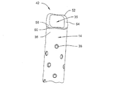
図5及び図6に示されているように、管10の遠位端42は、遠位開口部35を取り囲むリップ部50を有する。リップ部50は、好ましくは、口腔の内側を傷つけないように滑らかな丸みを帯び、遠位部14の外側表面36から半径方向外向きに延びる。リップ部50は、好ましくは、遠位開口部35の外側周縁部全体の周りに延びる。
As shown in FIGS. 5 and 6, the
遠位開口部35の大部分は、長手方向軸32に対してある角度を成し、その角度は90度ではない(すなわち、長手方向軸23に対して垂直ではない)。リップ部50の遠位端は、長手方向軸32に対して80度から90度までの角度で配置された第1の部分52と、長手方向軸32に対して30度から50度までの角度で配置された第2の部分54と、長手方向軸32に対して80度から90度までの角度で配置された第3の部分56とを有している。
Most of the
歯科管10は、好ましくは一部品として作成され、高密度ポリエチレンのような加工可能な剛性の熱可塑性物質から作成される。非熱可塑性物質を含む他の材料を使用することも可能であるものと考えられる。
The
歯科管10によれば、管の一部が口腔の一部又は他の物体によって遮られているときであっても、歯の治療中に十分な吸引能力が得られるという利点が得られる。歯科管10は、使用されたときに、孔の形のおかげで、人間工学的に心地よく、静かである。
The
例示のために、本発明の特定の好ましい実施形態を詳細に開示したが、部品の配置変更のような、開示した装置の変更又は修正は、本発明の範囲内にあるものと考えられる。 For the purpose of illustration, certain preferred embodiments of the invention have been disclosed in detail, but changes or modifications to the disclosed apparatus, such as changes in the arrangement of parts, are considered to be within the scope of the invention.
10 歯科吸引管
12 近位部
14 遠位部
21 外側表面
22 内側表面
30 第1の長手方向軸
32 第2の長手方向軸
35 遠位開口部
38 孔
50 リップ部
10
Claims (15)
外側表面、内側表面、近位部、及び遠位部を有する細長い実質的に管状の部材を含み、前記近位部は、第1の長手方向軸を規定し、前記遠位部は、前記近位部から延び、第2の長手方向軸を規定し、前記第1の長手方向軸は、前記第2の長手方向軸に対して150度から180度までの角度であり、複数の孔が、前記遠位部の少なくとも一部に螺旋状に配置され、各孔は、前記実質的に管状の部材の前記外側表面から前記内側表面まで延びる、歯科吸引装置。 A dental suction device,
An elongated substantially tubular member having an outer surface, an inner surface, a proximal portion, and a distal portion, wherein the proximal portion defines a first longitudinal axis and the distal portion is the proximal portion Extending from the position and defining a second longitudinal axis, wherein the first longitudinal axis is an angle from 150 degrees to 180 degrees with respect to the second longitudinal axis, and the plurality of holes are A dental suction device disposed in a spiral on at least a portion of the distal portion, each hole extending from the outer surface to the inner surface of the substantially tubular member.
前記近位部に結合され、前記近位部から遠くへ延びる遠位部であって、吸引によるその中を通した物質の移動を可能とするための実質的に中空の内部を有し、開口部を有する遠位部を規定する遠位部と、
前記遠位部に配置された複数の孔であって、前記遠位端開口部の断面積に対する前記孔の合計断面積の比率が約40%から約70%までの範囲内にある、複数の孔と
からなる歯科吸引装置。 A proximal portion having a substantially hollow interior to allow movement of the substance therethrough by suction;
A distal portion coupled to the proximal portion and extending away from the proximal portion having a substantially hollow interior to allow movement of the substance therethrough by suction; A distal portion defining a distal portion having a portion;
A plurality of holes disposed in the distal portion, wherein a ratio of a total cross-sectional area of the holes to a cross-sectional area of the distal end opening is in a range of about 40% to about 70%; Dental suction device consisting of holes.
外装壁を有する、実質的に管状の近位部であって、前記外壁が、その中を通した物質の輸送のための実質的に中空の内部を規定する、近位部と、
前記近位部に連通し、その中を通した物質の輸送のための実質的に中空の内部を有する遠位部であって、前記遠位部が、長手全長、開口部を備えた遠位端、及び少なくとも10個の孔を備えた少なくとも1つの外装壁を有し、前記孔がそれぞれ、前記遠位部の前記全長の約5%から約15%までの距離だけ、他の孔から間隔を空けて配置される、遠位部と
からなる歯科吸引管。 A dental suction tube,
A substantially tubular proximal portion having an exterior wall, wherein the outer wall defines a substantially hollow interior for transport of material therethrough;
A distal portion in communication with the proximal portion and having a substantially hollow interior for transport of material therethrough, the distal portion having a longitudinal length and a distal end with an opening And at least one exterior wall with at least 10 holes, each of which is spaced from another hole by a distance of about 5% to about 15% of the total length of the distal portion. A dental suction tube consisting of a distal part and a distal part.
Applications Claiming Priority (2)
| Application Number | Priority Date | Filing Date | Title |
|---|---|---|---|
| US13/627,521 US9532857B2 (en) | 2012-09-26 | 2012-09-26 | Dental suction tubing |
| US13/627,521 | 2012-09-26 |
Related Child Applications (1)
| Application Number | Title | Priority Date | Filing Date |
|---|---|---|---|
| JP2018072222A Division JP2018103005A (en) | 2012-09-26 | 2018-04-04 | Dental suction tube |
Publications (2)
| Publication Number | Publication Date |
|---|---|
| JP2014064893A true JP2014064893A (en) | 2014-04-17 |
| JP2014064893A5 JP2014064893A5 (en) | 2016-07-21 |
Family
ID=48874861
Family Applications (2)
| Application Number | Title | Priority Date | Filing Date |
|---|---|---|---|
| JP2013163803A Pending JP2014064893A (en) | 2012-09-26 | 2013-08-07 | Dental suction tube |
| JP2018072222A Pending JP2018103005A (en) | 2012-09-26 | 2018-04-04 | Dental suction tube |
Family Applications After (1)
| Application Number | Title | Priority Date | Filing Date |
|---|---|---|---|
| JP2018072222A Pending JP2018103005A (en) | 2012-09-26 | 2018-04-04 | Dental suction tube |
Country Status (4)
| Country | Link |
|---|---|
| US (1) | US9532857B2 (en) |
| EP (1) | EP2712576B1 (en) |
| JP (2) | JP2014064893A (en) |
| CA (1) | CA2820948C (en) |
Cited By (1)
| Publication number | Priority date | Publication date | Assignee | Title |
|---|---|---|---|---|
| JP2022512070A (en) * | 2018-12-11 | 2022-02-02 | キム、チェヨン | Suction tip |
Families Citing this family (13)
| Publication number | Priority date | Publication date | Assignee | Title |
|---|---|---|---|---|
| AU362765S (en) * | 2015-01-09 | 2015-07-20 | Unistraw Holdings Pte Ltd | A Straw |
| CN106264431A (en) * | 2015-06-01 | 2017-01-04 | 陈俊龙 | Dental mouth mirror |
| TWI581751B (en) * | 2015-06-01 | 2017-05-11 | 陳俊龍 | Dental mirror |
| GB201617529D0 (en) * | 2016-10-14 | 2016-11-30 | Wakefield Simon J | Device |
| US11141250B2 (en) * | 2018-03-07 | 2021-10-12 | SafeVac, LLC | Suction tool |
| USD870897S1 (en) * | 2018-06-21 | 2019-12-24 | Oral Diagnostix LLC | Medical probe |
| US10709532B2 (en) | 2018-07-01 | 2020-07-14 | Igor Roshkovan | Atraumatic high-volume dental evacuation tip |
| USD886984S1 (en) * | 2018-11-29 | 2020-06-09 | PTW Design & Development, Inc. | Pneumatic oral interface |
| US11278383B2 (en) | 2020-05-04 | 2022-03-22 | Stoma Ventures, LLC | Disposable dental aerosol device |
| US11896453B2 (en) * | 2020-05-08 | 2024-02-13 | Mark G. PALUMBO | Extra oral dental ventilator |
| WO2022016182A1 (en) * | 2020-07-15 | 2022-01-20 | Stoma Ventures, LLC | Disposable dental aerosol device |
| US20220160462A1 (en) * | 2020-11-20 | 2022-05-26 | Michael Allan Wickheim | Connection adaptor for use with dental tools |
| CA3148852A1 (en) * | 2021-02-12 | 2022-08-12 | M.N. Parchewsky Professional Corporation | Evacuation apparatus and method |
Citations (5)
| Publication number | Priority date | Publication date | Assignee | Title |
|---|---|---|---|---|
| US3225444A (en) * | 1963-10-14 | 1965-12-28 | Instro Dynamics Corp | Chin-secured dental aspirator |
| JPH08117257A (en) * | 1994-10-26 | 1996-05-14 | Toppan Printing Co Ltd | Aspirator for dental examination |
| JP2002534222A (en) * | 1999-01-12 | 2002-10-15 | バルトローメ,フランシス | Drainage cannula for medical surgery |
| US20100203470A1 (en) * | 2009-02-06 | 2010-08-12 | Jessy S. Sidhu, Professional Corporation | Dental evacuation tool |
| US20120237894A1 (en) * | 2009-08-04 | 2012-09-20 | University Of Manitoba | Dental apparatus |
Family Cites Families (25)
| Publication number | Priority date | Publication date | Assignee | Title |
|---|---|---|---|---|
| US3460255A (en) * | 1967-10-03 | 1969-08-12 | Clifford L Hutson | Oral evacuator |
| FR2240026A1 (en) | 1973-08-06 | 1975-03-07 | Rhone Poulenc Sa | Drain for medical use - has external lengthwise groove communicating with interior passage |
| US4068664A (en) | 1976-02-25 | 1978-01-17 | Texas Medical Products, Inc. | Surgical suction wand assembly and method |
| JPS57501463A (en) | 1980-09-04 | 1982-08-19 | ||
| US4487600A (en) | 1981-11-09 | 1984-12-11 | Brownlie Alan W | Adjustable suction device for medical use |
| US4695253A (en) | 1985-03-08 | 1987-09-22 | Tysse Thomas M | Oral evacuation device and method |
| US4767404A (en) * | 1986-07-14 | 1988-08-30 | R & S Associates Co. | Surgical suction device having a perforated sleeve |
| US4867747A (en) | 1987-03-23 | 1989-09-19 | Yarger Richard J | Surgical aspirator sleeve |
| US4950232A (en) * | 1987-08-11 | 1990-08-21 | Surelab Superior Research Laboratories | Cerebrospinal fluid shunt system |
| SE9101387L (en) * | 1991-05-06 | 1992-11-07 | Ernst Orsing | PROCEDURES FOR MANUFACTURE OF SALIVATORS |
| US5195952A (en) * | 1992-02-25 | 1993-03-23 | Albert Solnit | Noise reducing aspirator |
| US5441410A (en) | 1992-04-13 | 1995-08-15 | Segerdal; Michael J. | Disposable saliva ejector |
| US5464397A (en) | 1994-01-11 | 1995-11-07 | Powers Jr.; Carleton A. | Bacteria valve |
| US5425637A (en) | 1994-03-31 | 1995-06-20 | 601976 Alebrta Ltd. | Method and apparatus for preventing a back flow of oral contaminants in a low volume suction line of a dental saliva ejector |
| US5489276A (en) | 1994-10-07 | 1996-02-06 | Kormed, Inc. | Vacuum tube tip construction |
| CA2173558C (en) | 1995-04-07 | 2006-06-13 | Ronald L. S. Whitehouse | Disposable oral suction tip |
| US5741134A (en) * | 1995-06-07 | 1998-04-21 | Filtertek Inc. | Filter and universal adapter for use with dental aspirator tips |
| US6969373B2 (en) * | 2001-04-13 | 2005-11-29 | Tricardia, Llc | Syringe system |
| US20030220611A1 (en) | 2002-05-22 | 2003-11-27 | Surgimark, Inc. | Aspirator sleeve and tip |
| DE10347829A1 (en) * | 2003-10-10 | 2005-05-25 | Coltène/Whaledent GmbH + Co. KG | Two component suction |
| US7335023B2 (en) | 2003-10-27 | 2008-02-26 | Mahlmann Lee A | Aspirator having a cushioned and aspiration controlling tip |
| JP4446182B2 (en) * | 2005-03-08 | 2010-04-07 | 美奈子 長谷川 | Dental care suction tip |
| US7625207B2 (en) * | 2006-12-15 | 2009-12-01 | Kimberly-Clark Worldwide, Inc. | Yankauer suction device with sleeve and wiper |
| JP2008278968A (en) * | 2007-05-08 | 2008-11-20 | Fujinon Corp | Insertion assisting tool for endoscope |
| EP2163274B1 (en) * | 2007-05-25 | 2012-05-23 | Senko Medical Instrument Manufacturing Co., Ltd. | Endotracheal tube insertion assist instrument |
-
2012
- 2012-09-26 US US13/627,521 patent/US9532857B2/en active Active
-
2013
- 2013-07-12 CA CA2820948A patent/CA2820948C/en active Active
- 2013-07-24 EP EP13177867.2A patent/EP2712576B1/en active Active
- 2013-08-07 JP JP2013163803A patent/JP2014064893A/en active Pending
-
2018
- 2018-04-04 JP JP2018072222A patent/JP2018103005A/en active Pending
Patent Citations (5)
| Publication number | Priority date | Publication date | Assignee | Title |
|---|---|---|---|---|
| US3225444A (en) * | 1963-10-14 | 1965-12-28 | Instro Dynamics Corp | Chin-secured dental aspirator |
| JPH08117257A (en) * | 1994-10-26 | 1996-05-14 | Toppan Printing Co Ltd | Aspirator for dental examination |
| JP2002534222A (en) * | 1999-01-12 | 2002-10-15 | バルトローメ,フランシス | Drainage cannula for medical surgery |
| US20100203470A1 (en) * | 2009-02-06 | 2010-08-12 | Jessy S. Sidhu, Professional Corporation | Dental evacuation tool |
| US20120237894A1 (en) * | 2009-08-04 | 2012-09-20 | University Of Manitoba | Dental apparatus |
Cited By (2)
| Publication number | Priority date | Publication date | Assignee | Title |
|---|---|---|---|---|
| JP2022512070A (en) * | 2018-12-11 | 2022-02-02 | キム、チェヨン | Suction tip |
| JP7215773B2 (en) | 2018-12-11 | 2023-01-31 | ディーマックス インターナショナル カンパニー、リミテッド | suction tip |
Also Published As
| Publication number | Publication date |
|---|---|
| JP2018103005A (en) | 2018-07-05 |
| EP2712576A2 (en) | 2014-04-02 |
| CA2820948C (en) | 2019-12-03 |
| CA2820948A1 (en) | 2014-03-26 |
| US9532857B2 (en) | 2017-01-03 |
| EP2712576A3 (en) | 2014-07-09 |
| EP2712576B1 (en) | 2018-09-12 |
| US20140087328A1 (en) | 2014-03-27 |
Similar Documents
| Publication | Publication Date | Title |
|---|---|---|
| JP2018103005A (en) | Dental suction tube | |
| US3768477A (en) | Tongue depressing aspirating tip | |
| ES2904484T3 (en) | Self-cleaning surgical suction device | |
| JP2017518859A (en) | Intraoral device and method of use thereof | |
| US20160100747A1 (en) | Rigid head for a body passage device | |
| US11826217B2 (en) | Dental mouthpiece | |
| US20070060793A1 (en) | Suction retraction instrument for surgery | |
| JP2014515644A5 (en) | ||
| CN112020341A (en) | Suction head | |
| US20130245613A1 (en) | Self-cleaning surgical suction device with interchangeable tips | |
| JP7158950B2 (en) | Endoscope aids, endoscopes, endoscope aids and endoscopes | |
| JP2006150052A (en) | Suction aid for catheter | |
| US10286125B2 (en) | Suction device for normal and viscous materials | |
| KR101522314B1 (en) | Mouth prop for suction | |
| JP2024508940A (en) | Medical opening suction device that is easy to put on and take off | |
| US8512038B2 (en) | Dental high volume suction tube with protective cap | |
| JP4853076B2 (en) | Oral suction device | |
| US20090136895A1 (en) | Evacuation Tips having Lateral Vents | |
| JP6139933B2 (en) | Attachment member, suction device, tubular member, and medical device | |
| JP6485908B2 (en) | Medical suction tool | |
| US8360773B2 (en) | Dental high volume suction tube with protective cap | |
| JP6320043B2 (en) | Suction device, suction tube for suction device, and cap for suction device | |
| JP6294598B2 (en) | Tubular member, suction device and medical device | |
| JP2007289243A (en) | Suction tip | |
| JP2004049637A (en) | Suction tool |
Legal Events
| Date | Code | Title | Description |
|---|---|---|---|
| A521 | Request for written amendment filed |
Free format text: JAPANESE INTERMEDIATE CODE: A523 Effective date: 20160602 |
|
| A621 | Written request for application examination |
Free format text: JAPANESE INTERMEDIATE CODE: A621 Effective date: 20160602 |
|
| A131 | Notification of reasons for refusal |
Free format text: JAPANESE INTERMEDIATE CODE: A131 Effective date: 20170516 |
|
| A521 | Request for written amendment filed |
Free format text: JAPANESE INTERMEDIATE CODE: A523 Effective date: 20170726 |
|
| A02 | Decision of refusal |
Free format text: JAPANESE INTERMEDIATE CODE: A02 Effective date: 20171205 |