JP2014063161A - Display device and method of driving the same - Google Patents
Display device and method of driving the same Download PDFInfo
- Publication number
- JP2014063161A JP2014063161A JP2013192114A JP2013192114A JP2014063161A JP 2014063161 A JP2014063161 A JP 2014063161A JP 2013192114 A JP2013192114 A JP 2013192114A JP 2013192114 A JP2013192114 A JP 2013192114A JP 2014063161 A JP2014063161 A JP 2014063161A
- Authority
- JP
- Japan
- Prior art keywords
- color data
- pixel
- white
- blue
- red
- Prior art date
- Legal status (The legal status is an assumption and is not a legal conclusion. Google has not performed a legal analysis and makes no representation as to the accuracy of the status listed.)
- Pending
Links
- 238000000034 method Methods 0.000 title claims abstract description 19
- 239000000284 extract Substances 0.000 claims description 6
- 238000009877 rendering Methods 0.000 description 30
- 238000010586 diagram Methods 0.000 description 21
- 101100355949 Caenorhabditis elegans spr-1 gene Proteins 0.000 description 4
- 239000010410 layer Substances 0.000 description 3
- 239000000463 material Substances 0.000 description 3
- 238000012986 modification Methods 0.000 description 2
- 230000004048 modification Effects 0.000 description 2
- 239000003990 capacitor Substances 0.000 description 1
- 239000003086 colorant Substances 0.000 description 1
- 230000003287 optical effect Effects 0.000 description 1
- 239000002356 single layer Substances 0.000 description 1
Images


Classifications
-
- G—PHYSICS
- G09—EDUCATION; CRYPTOGRAPHY; DISPLAY; ADVERTISING; SEALS
- G09G—ARRANGEMENTS OR CIRCUITS FOR CONTROL OF INDICATING DEVICES USING STATIC MEANS TO PRESENT VARIABLE INFORMATION
- G09G3/00—Control arrangements or circuits, of interest only in connection with visual indicators other than cathode-ray tubes
- G09G3/20—Control arrangements or circuits, of interest only in connection with visual indicators other than cathode-ray tubes for presentation of an assembly of a number of characters, e.g. a page, by composing the assembly by combination of individual elements arranged in a matrix no fixed position being assigned to or needed to be assigned to the individual characters or partial characters
- G09G3/22—Control arrangements or circuits, of interest only in connection with visual indicators other than cathode-ray tubes for presentation of an assembly of a number of characters, e.g. a page, by composing the assembly by combination of individual elements arranged in a matrix no fixed position being assigned to or needed to be assigned to the individual characters or partial characters using controlled light sources
- G09G3/30—Control arrangements or circuits, of interest only in connection with visual indicators other than cathode-ray tubes for presentation of an assembly of a number of characters, e.g. a page, by composing the assembly by combination of individual elements arranged in a matrix no fixed position being assigned to or needed to be assigned to the individual characters or partial characters using controlled light sources using electroluminescent panels
- G09G3/32—Control arrangements or circuits, of interest only in connection with visual indicators other than cathode-ray tubes for presentation of an assembly of a number of characters, e.g. a page, by composing the assembly by combination of individual elements arranged in a matrix no fixed position being assigned to or needed to be assigned to the individual characters or partial characters using controlled light sources using electroluminescent panels semiconductive, e.g. using light-emitting diodes [LED]
- G09G3/3208—Control arrangements or circuits, of interest only in connection with visual indicators other than cathode-ray tubes for presentation of an assembly of a number of characters, e.g. a page, by composing the assembly by combination of individual elements arranged in a matrix no fixed position being assigned to or needed to be assigned to the individual characters or partial characters using controlled light sources using electroluminescent panels semiconductive, e.g. using light-emitting diodes [LED] organic, e.g. using organic light-emitting diodes [OLED]
- G09G3/3275—Details of drivers for data electrodes
- G09G3/3291—Details of drivers for data electrodes in which the data driver supplies a variable data voltage for setting the current through, or the voltage across, the light-emitting elements
-
- G—PHYSICS
- G09—EDUCATION; CRYPTOGRAPHY; DISPLAY; ADVERTISING; SEALS
- G09G—ARRANGEMENTS OR CIRCUITS FOR CONTROL OF INDICATING DEVICES USING STATIC MEANS TO PRESENT VARIABLE INFORMATION
- G09G3/00—Control arrangements or circuits, of interest only in connection with visual indicators other than cathode-ray tubes
- G09G3/20—Control arrangements or circuits, of interest only in connection with visual indicators other than cathode-ray tubes for presentation of an assembly of a number of characters, e.g. a page, by composing the assembly by combination of individual elements arranged in a matrix no fixed position being assigned to or needed to be assigned to the individual characters or partial characters
- G09G3/2003—Display of colours
-
- G—PHYSICS
- G09—EDUCATION; CRYPTOGRAPHY; DISPLAY; ADVERTISING; SEALS
- G09G—ARRANGEMENTS OR CIRCUITS FOR CONTROL OF INDICATING DEVICES USING STATIC MEANS TO PRESENT VARIABLE INFORMATION
- G09G3/00—Control arrangements or circuits, of interest only in connection with visual indicators other than cathode-ray tubes
- G09G3/20—Control arrangements or circuits, of interest only in connection with visual indicators other than cathode-ray tubes for presentation of an assembly of a number of characters, e.g. a page, by composing the assembly by combination of individual elements arranged in a matrix no fixed position being assigned to or needed to be assigned to the individual characters or partial characters
- G09G3/22—Control arrangements or circuits, of interest only in connection with visual indicators other than cathode-ray tubes for presentation of an assembly of a number of characters, e.g. a page, by composing the assembly by combination of individual elements arranged in a matrix no fixed position being assigned to or needed to be assigned to the individual characters or partial characters using controlled light sources
- G09G3/30—Control arrangements or circuits, of interest only in connection with visual indicators other than cathode-ray tubes for presentation of an assembly of a number of characters, e.g. a page, by composing the assembly by combination of individual elements arranged in a matrix no fixed position being assigned to or needed to be assigned to the individual characters or partial characters using controlled light sources using electroluminescent panels
- G09G3/32—Control arrangements or circuits, of interest only in connection with visual indicators other than cathode-ray tubes for presentation of an assembly of a number of characters, e.g. a page, by composing the assembly by combination of individual elements arranged in a matrix no fixed position being assigned to or needed to be assigned to the individual characters or partial characters using controlled light sources using electroluminescent panels semiconductive, e.g. using light-emitting diodes [LED]
- G09G3/3208—Control arrangements or circuits, of interest only in connection with visual indicators other than cathode-ray tubes for presentation of an assembly of a number of characters, e.g. a page, by composing the assembly by combination of individual elements arranged in a matrix no fixed position being assigned to or needed to be assigned to the individual characters or partial characters using controlled light sources using electroluminescent panels semiconductive, e.g. using light-emitting diodes [LED] organic, e.g. using organic light-emitting diodes [OLED]
- G09G3/3225—Control arrangements or circuits, of interest only in connection with visual indicators other than cathode-ray tubes for presentation of an assembly of a number of characters, e.g. a page, by composing the assembly by combination of individual elements arranged in a matrix no fixed position being assigned to or needed to be assigned to the individual characters or partial characters using controlled light sources using electroluminescent panels semiconductive, e.g. using light-emitting diodes [LED] organic, e.g. using organic light-emitting diodes [OLED] using an active matrix
- G09G3/3233—Control arrangements or circuits, of interest only in connection with visual indicators other than cathode-ray tubes for presentation of an assembly of a number of characters, e.g. a page, by composing the assembly by combination of individual elements arranged in a matrix no fixed position being assigned to or needed to be assigned to the individual characters or partial characters using controlled light sources using electroluminescent panels semiconductive, e.g. using light-emitting diodes [LED] organic, e.g. using organic light-emitting diodes [OLED] using an active matrix with pixel circuitry controlling the current through the light-emitting element
-
- H—ELECTRICITY
- H10—SEMICONDUCTOR DEVICES; ELECTRIC SOLID-STATE DEVICES NOT OTHERWISE PROVIDED FOR
- H10K—ORGANIC ELECTRIC SOLID-STATE DEVICES
- H10K50/00—Organic light-emitting devices
- H10K50/80—Constructional details
- H10K50/805—Electrodes
-
- H—ELECTRICITY
- H10—SEMICONDUCTOR DEVICES; ELECTRIC SOLID-STATE DEVICES NOT OTHERWISE PROVIDED FOR
- H10K—ORGANIC ELECTRIC SOLID-STATE DEVICES
- H10K59/00—Integrated devices, or assemblies of multiple devices, comprising at least one organic light-emitting element covered by group H10K50/00
- H10K59/10—OLED displays
- H10K59/12—Active-matrix OLED [AMOLED] displays
- H10K59/131—Interconnections, e.g. wiring lines or terminals
-
- H—ELECTRICITY
- H10—SEMICONDUCTOR DEVICES; ELECTRIC SOLID-STATE DEVICES NOT OTHERWISE PROVIDED FOR
- H10K—ORGANIC ELECTRIC SOLID-STATE DEVICES
- H10K59/00—Integrated devices, or assemblies of multiple devices, comprising at least one organic light-emitting element covered by group H10K50/00
- H10K59/30—Devices specially adapted for multicolour light emission
- H10K59/35—Devices specially adapted for multicolour light emission comprising red-green-blue [RGB] subpixels
- H10K59/352—Devices specially adapted for multicolour light emission comprising red-green-blue [RGB] subpixels the areas of the RGB subpixels being different
-
- G—PHYSICS
- G09—EDUCATION; CRYPTOGRAPHY; DISPLAY; ADVERTISING; SEALS
- G09G—ARRANGEMENTS OR CIRCUITS FOR CONTROL OF INDICATING DEVICES USING STATIC MEANS TO PRESENT VARIABLE INFORMATION
- G09G2300/00—Aspects of the constitution of display devices
- G09G2300/04—Structural and physical details of display devices
- G09G2300/0439—Pixel structures
- G09G2300/0452—Details of colour pixel setup, e.g. pixel composed of a red, a blue and two green components
-
- G—PHYSICS
- G09—EDUCATION; CRYPTOGRAPHY; DISPLAY; ADVERTISING; SEALS
- G09G—ARRANGEMENTS OR CIRCUITS FOR CONTROL OF INDICATING DEVICES USING STATIC MEANS TO PRESENT VARIABLE INFORMATION
- G09G2300/00—Aspects of the constitution of display devices
- G09G2300/04—Structural and physical details of display devices
- G09G2300/0439—Pixel structures
- G09G2300/0465—Improved aperture ratio, e.g. by size reduction of the pixel circuit, e.g. for improving the pixel density or the maximum displayable luminance or brightness
-
- G—PHYSICS
- G09—EDUCATION; CRYPTOGRAPHY; DISPLAY; ADVERTISING; SEALS
- G09G—ARRANGEMENTS OR CIRCUITS FOR CONTROL OF INDICATING DEVICES USING STATIC MEANS TO PRESENT VARIABLE INFORMATION
- G09G2340/00—Aspects of display data processing
- G09G2340/04—Changes in size, position or resolution of an image
- G09G2340/0457—Improvement of perceived resolution by subpixel rendering
-
- G—PHYSICS
- G09—EDUCATION; CRYPTOGRAPHY; DISPLAY; ADVERTISING; SEALS
- G09G—ARRANGEMENTS OR CIRCUITS FOR CONTROL OF INDICATING DEVICES USING STATIC MEANS TO PRESENT VARIABLE INFORMATION
- G09G2340/00—Aspects of display data processing
- G09G2340/06—Colour space transformation
Abstract
Description
本発明の技術的思想は、表示装置に係り、特に、ホワイトサブピクセルを含む表示装置のピクセルアレイに関する。 The technical idea of the present invention relates to a display device, and more particularly to a pixel array of a display device including white subpixels.
本発明の技術的思想は、表示装置の駆動方法に係り、特に、ホワイトサブピクセルを含む表示装置のピクセルアレイの駆動方法に関する。 The technical idea of the present invention relates to a driving method of a display device, and more particularly, to a driving method of a pixel array of a display device including white subpixels.
最近OLED(Organic Light Emitting Diode) TV分野では、既存のRGB OLED以外に、高解像度の大面積OLED製作に有利なWOLED技術が活発に論議されている。WOLEDは、白色のサブピクセルをさらに含み、RGB信号で白色に具現できるカラーデータ部分を、カラーフィルタを使わずに具現できる。また、カラーフィルタを使わずに具現できるため、カラーフィルタによる光度減少も発生しない。 Recently, in the OLED (Organic Light Emitting Diode) TV field, in addition to the existing RGB OLED, WOLED technology advantageous for producing a high-resolution large-area OLED has been actively discussed. The WOLED further includes a white sub-pixel, and can implement a color data portion that can be realized in white by an RGB signal without using a color filter. Moreover, since it can be implemented without using a color filter, the light intensity does not decrease due to the color filter.
WOLED表示装置のディスプレイパネルで使うRGBWサブピクセルの配列は、RGBWチェッカー(Checker)及びRGBWストライプなどがある。これらのRGBWサブピクセルの配列は、既存のRGB OLEDで使われたサブピクセルの配列とは異なって、これを駆動する回路が変更されねばならない。例えば、RGBWチェッカー構造の場合、スキャンチャネルの数が2倍に増加し、駆動回路のチャージタイム(Charge)及び駆動周波数が変わる。また、RGBWストライプは、データチャネルの数が増加し、ソースドライバのパッドの数が増加し、ソースドライバ回路のサイズが増大する。 The RGBW subpixel array used in the display panel of the WOLED display device includes an RGBW checker and an RGBW stripe. The array of these RGBW sub-pixels is different from the array of sub-pixels used in the existing RGB OLED, and a circuit for driving the same must be changed. For example, in the case of the RGBW checker structure, the number of scan channels is doubled, and the charge time (Charge) and drive frequency of the drive circuit are changed. In addition, the RGBW stripe increases the number of data channels, increases the number of source driver pads, and increases the size of the source driver circuit.
本発明の技術的思想が解決しようとする課題は、RGB OLEDに用いられた駆動回路を使ってスキャンチャネルまたはデータチャネルの増加を回避し、駆動回路の面積の増加、チャージタイム変動、駆動周波数変動などを防止するところにある。 The problem to be solved by the technical idea of the present invention is to avoid an increase in scan channel or data channel by using a drive circuit used in RGB OLED, and to increase the area of the drive circuit, charge time fluctuation, drive frequency fluctuation. It is a place to prevent.
本発明の一実施形態による表示装置は、赤色(R)、緑色(G)、白色(W)をそれぞれ具現する3個のサブピクセルを含む第1ピクセルと、前記第1ピクセルに隣接し、青色(B)、緑色(G)、白色(W)をそれぞれ具現する3個のサブピクセルを含む第2ピクセルと、を含む。 According to an exemplary embodiment of the present invention, a display device includes a first pixel including three sub-pixels that implement red (R), green (G), and white (W), and a blue pixel adjacent to the first pixel. (B), green (G), and white (W), and a second pixel including three subpixels.
望ましくは、前記第1ピクセルに対応する第1入力カラーデータ及び前記第2ピクセルに対応する第2入力カラーデータを受信し、前記第1ピクセルに含まれた赤色、緑色、白色サブピクセルそれぞれに対応する第1出力カラーデータ、及び前記第2ピクセルに含まれた青色、緑色、白色サブピクセルそれぞれに対応する第2出力カラーデータを生成するカラーデータ変換器をさらに備えることを特徴とする。 Preferably, the first input color data corresponding to the first pixel and the second input color data corresponding to the second pixel are received and correspond to each of the red, green, and white subpixels included in the first pixel. And a color data converter for generating second output color data corresponding to each of the blue, green, and white sub-pixels included in the second pixel.
望ましくは、前記第1入力カラーデータ及び前記第2入力カラーデータは、それぞれ赤色、緑色、青色入力カラーデータであることを特徴とする。 Preferably, the first input color data and the second input color data are red, green, and blue input color data, respectively.
望ましくは、前記カラーデータ変換器では、前記第2入力カラーデータのうち赤色カラーデータ部分が、前記第1ピクセルの赤色サブピクセルで具現され、前記第1入力カラーデータのうち青色カラーデータ部分が、前記第2ピクセルの青色サブピクセルで具現されるように、前記第1出力カラーデータ及び第2出力カラーデータを生成することを特徴とする。 Preferably, in the color data converter, a red color data portion of the second input color data is implemented by a red subpixel of the first pixel, and a blue color data portion of the first input color data is The first output color data and the second output color data may be generated as implemented by a blue sub-pixel of the second pixel.
望ましくは、前記カラーデータ変換器では、前記第1入力カラーデータ及び前記第2入力カラーデータのうち赤色カラーデータ部分が、前記第1ピクセルの赤色サブピクセル及び白色サブピクセル、前記第2ピクセルの白色サブピクセルのうち少なくとも一つで具現され、前記第1入力カラーデータ及び前記第2入力カラーデータのうち青色カラーデータ部分が、前記第2ピクセルの青色サブピクセル及び白色サブピクセル、前記第1ピクセルの白色サブピクセルのうち少なくとも一つで具現されるように、前記第1出力カラーデータ及び第2出力カラーデータを生成することを特徴とする。 Preferably, in the color data converter, a red color data portion of the first input color data and the second input color data includes a red subpixel and a white subpixel of the first pixel, and a white color of the second pixel. The blue color data portion of the first input color data and the second input color data may be a blue subpixel and a white subpixel of the second pixel, and the first pixel. The first output color data and the second output color data are generated as implemented by at least one of white subpixels.
望ましくは、前記カラーデータ変換器は、前記第1入力カラーデータから白色カラーに具現される最大値を抽出し、抽出された値と第1ゲイン比率gain ratio_1とを乗算して第1白色出力カラーデータを定めることを特徴とする。 Preferably, the color data converter extracts a maximum value embodied in white color from the first input color data, and multiplies the extracted value by a first gain ratio gain_1 to obtain a first white output color. It is characterized by defining data.
望ましくは、前記カラーデータ変換器は、前記第1入力カラーデータのうち青色カラーデータから前記第1白色出力カラーデータを減算した値に基づいて、第2出力カラーデータのうち青色出力カラーデータを定めることを特徴とする。 Preferably, the color data converter determines blue output color data of the second output color data based on a value obtained by subtracting the first white output color data from the blue color data of the first input color data. It is characterized by that.
望ましくは、前記カラーデータ変換器は、前記第2入力カラーデータから白色カラーに具現される最大値を抽出し、抽出された値と第2ゲイン比率gain ratio_2とを乗算して第2白色出力カラーデータを定めることを特徴とする。 Preferably, the color data converter extracts a maximum value embodied in white color from the second input color data, and multiplies the extracted value by a second gain ratio gain_2 to generate a second white output color. It is characterized by defining data.
望ましくは、前記カラーデータ変換器は、前記第2入力カラーデータのうち赤色カラーデータから前記第2白色出力カラーデータを減算した値に基づいて、第1出力カラーデータのうち赤色出力カラーデータを定めることを特徴とする。 Preferably, the color data converter determines red output color data of the first output color data based on a value obtained by subtracting the second white output color data from the red color data of the second input color data. It is characterized by that.
望ましくは、前記第1ピクセル及び前記第2ピクセルが複数であることを特徴とするディスプレイパネルを備える。 Preferably, the display panel includes a plurality of the first pixels and the second pixels.
望ましくは、前記複数の第1ピクセルに対応する複数の第1入力カラーデータ、及び前記複数の第2ピクセルに対応する複数の第2入力カラーデータを受信し、前記複数の第1ピクセルに含まれた赤色、緑色、白色サブピクセルそれぞれに対応する複数の第1出力カラーデータ、及び前記複数の第2ピクセルに含まれた青色、緑色、白色サブピクセルそれぞれに対応する複数の第2出力カラーデータを生成するカラーデータ変換器をさらに備えることを特徴とする。 Preferably, the plurality of first input color data corresponding to the plurality of first pixels and the plurality of second input color data corresponding to the plurality of second pixels are received and included in the plurality of first pixels. A plurality of first output color data corresponding to each of the red, green and white subpixels, and a plurality of second output color data corresponding to each of the blue, green and white subpixels included in the plurality of second pixels. It further comprises a color data converter to be generated.
望ましくは、前記カラーデータ変換器では、前記複数の第2入力カラーデータのうち赤色カラーデータ部分が、前記複数の第1ピクセルの赤色サブピクセルで具現され、前記複数の第1入力カラーデータのうち青色カラーデータ部分が、前記複数の第2ピクセルの青色サブピクセルで具現されるように、前記第1出力カラーデータ及び第2出力カラーデータを生成することを特徴とする。 Preferably, in the color data converter, a red color data portion of the plurality of second input color data is implemented by red sub-pixels of the plurality of first pixels, and among the plurality of first input color data. The first output color data and the second output color data are generated so that a blue color data portion is implemented by blue subpixels of the plurality of second pixels.
望ましくは、前記カラーデータ変換器では、前記複数の第1入力カラーデータ及び前記複数の第2入力カラーデータのうち赤色カラーデータが、前記複数の第1ピクセルの赤色サブピクセル及び白色サブピクセル、前記複数の第2ピクセルの白色サブピクセルのうち少なくとも一つで具現され、前記複数の第1入力カラーデータ及び前記複数の第2入力カラーデータのうち青色カラーデータが、前記複数の第2ピクセルの青色サブピクセル及び白色サブピクセル、前記複数の第1ピクセルの白色サブピクセルのうち少なくとも一つで具現されるように、前記複数の第1出力カラーデータ及び複数の第2出力カラーデータを生成することを特徴とする。 Preferably, in the color data converter, red color data among the plurality of first input color data and the plurality of second input color data are red subpixels and white subpixels of the plurality of first pixels, A plurality of second sub-pixel white sub-pixels may be implemented, and blue color data of the plurality of first input color data and the plurality of second input color data may be blue of the plurality of second pixels. Generating the plurality of first output color data and the plurality of second output color data so as to be implemented by at least one of a subpixel, a white subpixel, and a white subpixel of the plurality of first pixels. Features.
本発明の他の実施形態による表示装置は、一つ以上の単位ピクセルを含むディスプレイパネルと、前記一つ以上の単位ピクセルそれぞれに3色データ信号を供給するデータドライバと、前記一つ以上の単位ピクセルにゲートオン電圧を供給するゲートドライバと、前記データドライバ及び前記ゲートドライバの駆動を制御するタイミングコントローラと、を備え、前記ディスプレイパネルは、赤色、緑色、白色をそれぞれ具現する3個のサブピクセルを含む第1ピクセルと、前記第1ピクセルに隣接し、青色、緑色、白色をそれぞれ具現する3個のサブピクセルを含む第2ピクセルと、を含むことを特徴とする。 According to another exemplary embodiment of the present invention, a display device includes a display panel including one or more unit pixels, a data driver supplying a three color data signal to each of the one or more unit pixels, and the one or more units. A gate driver that supplies a gate-on voltage to the pixel; and a timing controller that controls driving of the data driver and the gate driver. The display panel includes three sub-pixels that implement red, green, and white, respectively. And a second pixel including three sub-pixels adjacent to the first pixel and embodying blue, green, and white, respectively.
望ましくは、前記タイミングコントローラは、前記第1ピクセルに対応する赤色、緑色、青色の第1入力カラーデータ、及び前記第2ピクセルに対応する赤色、緑色、青色の第2入力カラーデータを受信することを特徴とする。 Preferably, the timing controller receives first input color data of red, green, and blue corresponding to the first pixel, and second input color data of red, green, and blue corresponding to the second pixel. It is characterized by.
望ましくは、前記タイミングコントローラは、前記第1入力カラーデータ及び前記第2入力カラーデータのうち赤色カラーデータ部分は、前記第1ピクセルの赤色サブピクセル及び白色サブピクセル、前記第2ピクセルの白色サブピクセルのうち少なくとも一つで具現され、前記第1入力カラーデータ及び前記第2入力カラーデータのうち青色カラーデータ部分は、前記第2ピクセルの青色サブピクセル及び白色サブピクセル、前記第1ピクセルの白色サブピクセルのうち少なくとも一つで具現されるように、前記第1出力カラーデータ及び第2出力カラーデータを生成することを特徴とする。 The timing controller may include a red color pixel portion of the first pixel and a white color subpixel of the second pixel, the red color data portion of the first input color data and the second input color data. The blue color data portion of the first input color data and the second input color data includes a blue sub-pixel and a white sub-pixel of the second pixel, and a white sub-pixel of the first pixel. The first output color data and the second output color data are generated as implemented by at least one of the pixels.
望ましくは、前記タイミングコントローラは、前記第1入力カラーデータから白色カラーに具現される最大値を抽出し、抽出された値と第1ゲイン比率ga1とを乗算して第1白色出力カラーデータを定めることを特徴とする。 Preferably, the timing controller extracts a maximum value embodied in white color from the first input color data, and multiplies the extracted value by a first gain ratio ga1 to determine first white output color data. It is characterized by that.
望ましくは、前記タイミングコントローラは、前記第1入力カラーデータのうち青色カラーデータから前記第1白色出力カラーデータを減算した値に基づいて、第2出力カラーデータのうち青色出力カラーデータを定めることを特徴とする。 Preferably, the timing controller determines blue output color data of the second output color data based on a value obtained by subtracting the first white output color data from the blue color data of the first input color data. Features.
望ましくは、前記第1ピクセル及び前記第2ピクセルが複数であることを特徴とするディスプレイパネルを備える。 Preferably, the display panel includes a plurality of the first pixels and the second pixels.
望ましくは、前記タイミングコントローラは、前記データドライバに、赤色、緑色及び白色サブピクセルそれぞれに対応する第1出力カラーデータ、または青色、緑色及び白色サブピクセルそれぞれに対応する第2出力カラーデータを供給することを特徴とする。 Preferably, the timing controller supplies the data driver with first output color data corresponding to red, green and white subpixels or second output color data corresponding to blue, green and white subpixels, respectively. It is characterized by that.
望ましくは、前記データドライバが供給する前記3色データ信号は、赤色、緑色及び白色出力カラーデータに対応する3色データ信号、または青色、緑色、白色出力カラーデータに対応する3色データ信号であることを特徴とする。 Preferably, the three-color data signal supplied by the data driver is a three-color data signal corresponding to red, green and white output color data, or a three-color data signal corresponding to blue, green and white output color data. It is characterized by that.
本発明のさらに他の実施形態による表示装置の駆動方法は、カラーデータ変換器が、第1ピクセルに対応する第1入力カラーデータ及び第2ピクセルに対応する第2入力カラーデータを受信する段階と、前記カラーデータ変換器が、前記第1ピクセルに含まれた赤色、緑色、白色サブピクセルそれぞれに対応する第1出力カラーデータ、及び前記第2ピクセルに含まれた青色、緑色、白色サブピクセルそれぞれに対応する第2出力カラーデータを生成する段階と、を含み、前記第1入力カラーデータ及び前記第2入力カラーデータは、それぞれ赤色、緑色、青色入力カラーデータであることを特徴とする。 According to another aspect of the present invention, there is provided a method of driving a display device, wherein a color data converter receives first input color data corresponding to a first pixel and second input color data corresponding to a second pixel. The color data converter includes first output color data corresponding to red, green, and white subpixels included in the first pixel, and blue, green, and white subpixels included in the second pixel, respectively. Generating second output color data corresponding to the first input color data and the second input color data are red, green, and blue input color data, respectively.
望ましくは、前記カラーデータ変換器では、前記第2入力カラーデータのうち赤色カラーデータ部分が、前記第1ピクセルの赤色サブピクセルで具現され、前記第1入力カラーデータのうち青色カラーデータ部分が、前記第2ピクセルの青色サブピクセルで具現されるように、前記第1出力カラーデータ及び第2出力カラーデータを生成する段階をさらに含むことを特徴とする。 Preferably, in the color data converter, a red color data portion of the second input color data is implemented by a red subpixel of the first pixel, and a blue color data portion of the first input color data is The method may further include generating the first output color data and the second output color data as embodied in the blue subpixel of the second pixel.
望ましくは、前記カラーデータ変換器では、前記第1入力カラーデータ及び前記第2入力カラーデータのうち赤色カラーデータ部分が、前記第1ピクセルの赤色サブピクセル及び白色サブピクセル、前記第2ピクセルの白色サブピクセルのうち少なくとも一つで具現され、前記第1入力カラーデータ及び前記第2入力カラーデータのうち青色カラーデータ部分が、前記第2ピクセルの青色サブピクセル及び白色サブピクセル、前記第1ピクセルの白色サブピクセルのうち少なくとも一つで具現されるように、前記第1出力カラーデータ及び第2出力カラーデータを生成する段階をさらに含むことを特徴とする。 Preferably, in the color data converter, a red color data portion of the first input color data and the second input color data includes a red subpixel and a white subpixel of the first pixel, and a white color of the second pixel. The blue color data portion of the first input color data and the second input color data may be a blue subpixel and a white subpixel of the second pixel, and the first pixel. The method may further include generating the first output color data and the second output color data as embodied by at least one of the white subpixels.
望ましくは、データドライバが前記第1出力カラーデータ及び前記第2出力カラーデータを受信する段階と、ゲートドライバが前記複数の単位ピクセルにゲートオン電圧を供給する段階と、データドライバが前記第1出力カラーデータ及び前記第2出力カラーデータに対応して、それぞれのピクセルにデータ信号を供給する段階と、を含む。 Preferably, a data driver receives the first output color data and the second output color data, a gate driver supplies a gate-on voltage to the plurality of unit pixels, and a data driver receives the first output color data. Supplying a data signal to each pixel corresponding to the data and the second output color data.
前述したような本発明による表示装置は、RGB OLEDに用いられた駆動回路を使って、スキャンチャネル及びデータチャネルの増加を回避し、駆動回路の面積の増加、チャージタイム変動、駆動周波数変動などを防止する。 The display device according to the present invention as described above avoids an increase in scan channel and data channel by using a drive circuit used for RGB OLED, and increases an area of the drive circuit, charge time fluctuation, drive frequency fluctuation, and the like. To prevent.
以下、添付した図面を参照して本発明の実施形態について詳細に説明する。本発明の実施形態は当業者に本発明をさらに完全に説明するために提供されるものである。本発明は多様な変更を加えることができ、かついろいろな形態を持つことができるが、ここでは特定実施形態を図面に例示して詳細に説明する。しかし、これは本発明を特定の開示形態に限定しようとするものではなく、本発明の思想及び技術範囲に含まれるあらゆる変更、均等物ないし代替物を含むと理解されねばならない。各図面を説明するに際して、類似した参照符号を類似した構成要素に付ける。添付した図面において、構造物の寸法は、本発明の明確性を期するために実際より拡大または縮小して図示したものである。 Hereinafter, embodiments of the present invention will be described in detail with reference to the accompanying drawings. Rather, these embodiments are provided so that this disclosure will be thorough and complete, and will fully convey the concept of the invention to those skilled in the art. While the present invention can be modified in various ways and can have various forms, specific embodiments will be described in detail with reference to the drawings. However, this should not be construed as limiting the invention to the particular forms disclosed, but should be understood to include any modifications, equivalents or alternatives that fall within the spirit and scope of the invention. In describing the drawings, like reference numerals will be used to refer to like elements. In the attached drawings, the dimensions of the structures are shown enlarged or reduced from the actual size for the sake of clarity of the present invention.
本願で使われた用語は、単に特定の実施形態を説明するために使われたものであり、本発明を限定しようとする意図ではない。単数の表現は、文脈上明らかに異なる意味として使用しない限り、複数の表現を含む。本願で、“含む”または“持つ”などの用語は、明細書上に記載の特徴、数字、段階、動作、構成要素、部分品またはこれらを組み合わせたものが存在することを指そうとするものであり、一つまたはそれ以上の他の特徴や数字、段階、動作、構成要素、部分品またはこれらを組み合わせたものなどの存在または付加可能性を予め排除しないと理解されねばならない。 The terminology used herein is for the purpose of describing particular embodiments only and is not intended to be limiting of the invention. The singular form includes the plural form unless the context clearly indicates otherwise. In this application, a term such as “including” or “having” is intended to indicate that a feature, number, step, operation, component, component, or combination thereof described in the specification exists. It should be understood that the existence or additional possibilities of one or more other features or numbers, steps, actions, components, components or combinations thereof are not excluded in advance.
また、第1、第2などの用語は、多様な構成要素の説明に使われるが、前記構成要素は前記用語によって限定されてはならない。前記用語は、一つの構成要素を他の構成要素から区別する目的で使われる。例えば、本発明の権利範囲から逸脱せずに、第1構成要素は第2構成要素と称され、類似して第2構成要素も第1構成要素と称される。 Further, the terms such as “first” and “second” are used to describe various components, but the components should not be limited by the terms. The terms are used for the purpose of distinguishing one component from other components. For example, without departing from the scope of the present invention, the first component is referred to as the second component, and similarly, the second component is also referred to as the first component.
特に定義されない限り、技術的や科学的な用語を含めて、ここで使われるすべての用語は、当業者によって一般的に理解されるところと同じ意味を持つ。一般的に使われる辞書に定義されているような用語は、関連技術の文脈上持つ意味と一致する意味を持つと解釈されねばならず、本願で明らかに定義しない限り、理想的または過度に形式的な意味で解釈されない。 Unless defined otherwise, all terms used herein, including technical and scientific terms, have the same meaning as commonly understood by one of ordinary skill in the art. Terms such as those defined in commonly used dictionaries should be construed to have meanings that are consistent with those in the context of the related art, and are ideally or overly formal unless clearly defined herein. It is not interpreted in a sense.
図1は、本発明の一実施形態による表示装置10のブロック図である。図1を参照すれば、表示装置10は、ディスプレイパネル100、タイミングコントローラ110、データドライバ120、ゲートドライバ130を備える。
FIG. 1 is a block diagram of a
ディスプレイパネル100には、複数のデータラインDLと複数のゲートラインGLとが互いに交差し、交差するディスプレイ領域に、3個のサブピクセルをそれぞれ含む複数のピクセルP1、P2が配される。
In the
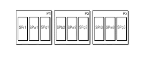
ピクセルP1は、R(赤色)光を発生させるためのRサブピクセルSPr1、G(緑色)光を発生させるためのGサブピクセルSPg1、及びW(白色)光を発生させるためのWサブピクセルSPw1を含む。一方、B(青色)光はピクセルP1で発生せず、周辺のピクセルのレンダリングによりB(青色)光を具現する。例えば、ピクセルP2のレンダリングによりB(青色)光を具現する。 The pixel P1 includes an R subpixel SPr1 for generating R (red) light, a G subpixel SPg1 for generating G (green) light, and a W subpixel SPw1 for generating W (white) light. Including. On the other hand, the B (blue) light is not generated in the pixel P1, and the B (blue) light is realized by rendering the surrounding pixels. For example, B (blue) light is implemented by rendering the pixel P2.
ピクセルP1と隣接するピクセルP2は、カラー具現のためにB(青色)光を発生させるためのBサブピクセルSPb2、G(緑色)光を発生させるためのGサブピクセルSPg2、及びW(白色)光を発生させるためのWサブピクセルSPw2を含む。一方、R(赤色)光はピクセルP2で発生せず、周辺のピクセルのレンダリングによりR(赤色)光を具現する。例えば、ピクセルP1のレンダリングによりR(赤色)光を具現する。 The pixel P2 adjacent to the pixel P1 includes a B sub-pixel SPb2 for generating B (blue) light for realizing color, a G sub-pixel SPg2 for generating G (green) light, and W (white) light. W sub-pixel SPw2 for generating. On the other hand, the R (red) light is not generated in the pixel P2, and the R (red) light is realized by rendering the surrounding pixels. For example, R (red) light is implemented by rendering the pixel P1.
本発明の一実施形態による、ディスプレイパネルに含まれる複数のピクセルは、それぞれ3個のサブピクセルを含む。それぞれのピクセルは、RサブピクセルまたはBサブピクセルを含まず、隣接するピクセルのレンダリングにより、含まれていないサブピクセルに対する光データを具現する。 According to an embodiment of the present invention, the plurality of pixels included in the display panel each include three subpixels. Each pixel does not include an R subpixel or a B subpixel, and realizes optical data for subpixels that are not included by rendering adjacent pixels.
図1で、2つのピクセルについて示したが、これは説明上の便宜のためのものであり、ディスプレイパネル100に含まれたピクセルの数は、適用アプリケーションによって変わる。
Although two pixels are shown in FIG. 1, this is for convenience of explanation, and the number of pixels included in the
図2Aないし図2Hは、ディスプレイパネル内で多様なサブピクセルの配列を示す図面である。図2Aないし図2Hは、それぞれ4個のピクセルを示し、それぞれのピクセルは3個のサブピクセルを含む。図2Aのように、第1ピクセルは、RWG順にサブピクセルを含み、第2ピクセルは、BWG順にサブピクセルを含む。それぞれのサブピクセルは、3個のデータラインと1個のゲートラインとの交差によってストライプ式の配列をなす。 2A to 2H are views illustrating various sub pixel arrangements in a display panel. 2A through 2H each show four pixels, each pixel including three sub-pixels. As shown in FIG. 2A, the first pixel includes sub-pixels in RWG order, and the second pixel includes sub-pixels in BWG order. Each sub-pixel forms a stripe arrangement by the intersection of three data lines and one gate line.
図2Bないし図2Hは、他のサブピクセルの配列を示す。それぞれの図2Bないし図2Hを参照すれば、それぞれのピクセルは、白色サブピクセル及び緑サブピクセルを含み、赤色または青色サブピクセルを交互に含む。同じピクセル内でサブピクセルの配置は、図2Aないし図2Hに示したように、多様に変更される。 2B to 2H show other subpixel arrangements. Referring to FIGS. 2B to 2H, each pixel includes a white sub-pixel and a green sub-pixel, and alternately includes red or blue sub-pixels. The arrangement of the sub-pixels in the same pixel can be variously changed as shown in FIGS. 2A to 2H.
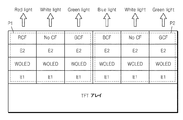
図3は、図1のピクセルP1及びピクセルP2内でサブピクセルの積層構成を示す図面である。図3を参照すれば、ピクセルP1は、サブピクセルSPr1、SPw1、SPg1を含む。ピクセルP2は、サブピクセルSPb2、SPw2、SPg2を含む。サブピクセルSPr1、SPw1、SPg1、SPb2、SPw2、SPg2は、ホワイトOLED(WOLED)をそれぞれ含む。ホワイトOLEDは、カソード電極とアノード電極との間に白色光を放出するように、赤色発光層、緑発光層及び青色発光層が積層された多層構造を持つか、または赤色発光物質、緑発光物質及び青色発光物質を含む単一層構造を持つ。 FIG. 3 is a diagram illustrating a stacked configuration of sub-pixels in the pixel P1 and the pixel P2 of FIG. Referring to FIG. 3, the pixel P1 includes subpixels SPr1, SPw1, and SPg1. The pixel P2 includes subpixels SPb2, SPw2, and SPg2. The subpixels SPr1, SPw1, SPg1, SPb2, SPw2, and SPg2 each include a white OLED (WOLED). The white OLED has a multilayer structure in which a red light emitting layer, a green light emitting layer, and a blue light emitting layer are laminated so as to emit white light between a cathode electrode and an anode electrode, or a red light emitting material and a green light emitting material. And a single layer structure including a blue light emitting material.
図3のように、RサブピクセルSPr1は、ホワイトOLEDから入射される白色光のうち赤色光のみを透過させるRカラーフィルタRCFを備え、GサブピクセルSPg1、SPg2は、ホワイトOLEDから入射される白色光のうち緑光のみを透過させるGカラーフィルタGCFを備え、BサブピクセルSPb2は、ホワイトOLEDから入射される白色光のうち青色光のみを透過させるBカラーフィルタBCFを備える。一方、WサブピクセルSPw1、SPw2は、カラーフィルタを備えず、ホワイトOLEDから入射される白色光をいずれも透過させることで、カラーフィルタRCF、GCF、BCFによる画像の輝度低下を補償する。 As shown in FIG. 3, the R subpixel SPr1 includes an R color filter RCF that transmits only red light out of white light incident from the white OLED, and the G subpixels SPg1 and SPg2 are white light incident from the white OLED. The G color filter GCF that transmits only green light out of the light is provided, and the B subpixel SPb2 includes a B color filter BCF that transmits only blue light out of the white light incident from the white OLED. On the other hand, the W sub-pixels SPw1 and SPw2 do not include a color filter, and pass white light incident from the white OLED, thereby compensating for a decrease in image luminance due to the color filters RCF, GCF, and BCF.
図3で、‘E1’は、アノード電極(または、カソード電極)であり、‘E2’は、カソード電極(または、アノード電極)でありうる。‘E1’は、サブピクセル単位であり、下部TFTアレイに形成された駆動TFTに電気的に接続される。TFTアレイは、サブピクセル別に駆動TFT、少なくともスイッチTFT、ストレージキャパシタなどを備え、サブピクセル単位でデータラインDL及びゲートラインGLに連結される。 In FIG. 3, 'E1' may be an anode electrode (or cathode electrode) and 'E2' may be a cathode electrode (or anode electrode). 'E1' is a sub-pixel unit and is electrically connected to the driving TFT formed in the lower TFT array. The TFT array includes a driving TFT, at least a switch TFT, and a storage capacitor for each subpixel, and is connected to the data line DL and the gate line GL in units of subpixels.
再び図1を参照すれば、データドライバ120は、タイミングコントローラ110の制御下で色座標が変換された出力カラーデータRo1、Go1、Wo1、Bo2、Go2、Wo2をアナログデータ電圧に変換し、データラインDLに供給する。
Referring back to FIG. 1, the
ゲートドライバ130は、タイミングコントローラ110の制御下でスキャンパルスを発生させてゲートラインGLに順次に供給することで、データ電圧が印加される水平ラインを選択する。
The
タイミングコントローラ110は、垂直同期信号Vsync、水平同期信号Hsync、クロック信号CLK及びデータイネーブル信号DEなどのタイミング信号に基づいて、データドライバ120の動作タイミングを制御するためのデータ制御信号DDCと、ゲートドライバ130の動作タイミングを制御するためのゲート制御信号GDCと、を発生させる。
The
タイミングコントローラ110は、カラーデータ変換器111を備える。カラーデータ変換器111は、外部から入力される3色の入力カラーデータRi1、Gi1、Bi1、Ri2、Gi2、Bi2を受信し、色座標が変換された出力カラーデータRo1、Go1、Wo1、Bo2、Go2、Wo2をデータドライバ120に供給する。但し、カラーデータ変換器111は、データドライバ120または別途のチップで具現され、アプリケーションによって変更可能である。
The
本発明の一実施形態による表示装置は、赤色、緑色、白色をそれぞれ具現するサブピクセルを含むピクセルP1及びピクセルP1に隣接し、青色、緑色、白色をそれぞれ具現するサブピクセルを含むピクセルP2を含むディスプレイパネルを備える。したがって、RGB OLEDの具現に使う駆動回路を使って、スキャンチャネル及びデータチャネルの増加をなくす。動作についての具体的な説明は後述する。 The display device according to an exemplary embodiment of the present invention includes a pixel P1 including sub-pixels that implement red, green, and white, and a pixel P2 that is adjacent to the pixel P1 and includes sub-pixels that implement blue, green, and white, respectively. A display panel is provided. Accordingly, an increase in scan channels and data channels is eliminated by using a driving circuit used to implement RGB OLED. A specific description of the operation will be described later.
図4Aは、本発明の一実施形態によって、2つのピクセルの間で具現されるレンダリングを説明するために、例示的にピクセルP1、ピクセルP2及びピクセルP3を示す図面である。 FIG. 4A is a diagram illustrating a pixel P1, a pixel P2, and a pixel P3 to illustrate rendering implemented between two pixels according to an embodiment of the present invention.
図4Aを参照すれば、ピクセルP1、P3は、赤色、白色、緑サブピクセルを含み、ピクセルP2は、青色、白色、緑サブピクセルを含む。ピクセルP1には、青色光を具現するサブピクセルがなく、ピクセルP2には、赤色光を具現するサブピクセルがない。よって、ピクセルP1に対応する青色入力カラーデータは、ピクセルP2のレンダリングにより具現され、ピクセルP2に対応する赤色入力カラーデータは、ピクセルP3のレンダリングにより具現される。 Referring to FIG. 4A, pixels P1 and P3 include red, white, and green subpixels, and pixel P2 includes blue, white, and green subpixels. The pixel P1 has no subpixel that implements blue light, and the pixel P2 has no subpixel that implements red light. Accordingly, the blue input color data corresponding to the pixel P1 is implemented by rendering the pixel P2, and the red input color data corresponding to the pixel P2 is implemented by rendering the pixel P3.
図4Bは、本発明の一実施形態による2つのピクセルの間で具現されるレンダリングを説明するためのカラーデータ変換器111を具体的に示す図面である。
FIG. 4B is a diagram illustrating a
図4B参照すれば、カラーデータ変換器111は、3色の入力カラーデータRi1、Gi1、Bi1;Ri2、Gi2、Bi2;Ri3、Gi3、Bi3を受信し、色座標が変換された出力カラーデータRo1、Go1、Wo1;Bo2、Go2、Wo2;Bo3、Go3、Wo3を生成する。カラーデータ変換器111は、ゲイン比率ga1、ga2、ga3を受信し、出力カラーデータRo1、Go1、Wo1;Bo2、Go2、Wo2;Ro3、Go3、Wo3の生成に用いる。
Referring to FIG. 4B, the
具体的に、カラーデータ変換器111は、ピクセルP1、ピクセルP2及びピクセルP3に対応する入力カラーデータRi1、Gi1、Bi1;Ri2、Gi2、Bi2;Ri3、Gi3、Bi3から、それぞれのピクセルで具現される白色出力カラーデータWo1、Wo2、Wo3を算出する。例えば、カラーデータ変換器111は、入力カラーデータRi1、Gi1、Bi1の最小値に第1ゲイン比率ga1を乗算し、ピクセルP1で具現される白色出力カラーデータWo1を算出する。例えば、カラーデータ変換器111は、入力カラーデータRi2、Gi2、Bi2の最小値に第2ゲイン比率ga2を乗算し、ピクセルP2で具現される白色出力カラーデータWo2を算出する。同様に、例えば入力カラーデータRi3、Gi3、Bi3の最小値に第3ゲイン比率ga3を乗算し、ピクセルP3で具現される白色出力カラーデータWo3を算出する。これを数式で表現すれば、次の通りである。
[数1]
Wo1=min(Ri1,Gi1,Bi1)×ga1
Wo2=min(Ri2,Gi2,Bi2)×ga2
Wo3=min(Ri3,Gi3,Bi3)×ga2
Specifically, the
[Equation 1]
Wo1 = min (Ri1, Gi1, Bi1) × ga1
Wo2 = min (Ri2, Gi2, Bi2) × ga2
Wo3 = min (Ri3, Gi3, Bi3) × ga2
ここで、第1ゲイン比率ga1、第2ゲイン比率ga2及び第3ゲイン比率ga3は、0と1との間の数字である。第1ゲイン比率ga1、第2ゲイン比率ga2及び第3ゲイン比率ga3は、カラーデータ変換器111の外部から入力される。
Here, the first gain ratio ga1, the second gain ratio ga2, and the third gain ratio ga3 are numbers between 0 and 1. The first gain ratio ga1, the second gain ratio ga2, and the third gain ratio ga3 are input from the outside of the
ディスプレイパネルに含まれたそれぞれのサブピクセルを駆動する時、白色を具現するために2つの方法が使われる。すなわち、白色を、カラーフィルタを経ない白色サブピクセルで具現できる一方、白色を、RGBカラーフィルタを通じて具現する赤色、緑色、青色カラーを組み合わせて具現できる。ゲイン比率は、白色を具現する時、ゲイン比率の高低に応じて2つの方法での白色の具現の仕方を変えさせる。すなわち、ゲイン比率が高い場合、白色を白色サブピクセルで具現する割合が高くなり、ゲイン比率が低い場合、白色を赤色、緑色、青色サブピクセルで具現する割合が高くなる。 When driving each sub-pixel included in the display panel, two methods are used to implement white color. That is, white can be implemented with white sub-pixels that do not pass through a color filter, while white can be implemented with a combination of red, green, and blue colors that are implemented through an RGB color filter. The gain ratio, when embodying white, changes the manner of embodying white in two ways depending on the gain ratio. That is, when the gain ratio is high, the ratio of realizing white with white subpixels is high, and when the gain ratio is low, the ratio of realizing white with red, green, and blue subpixels is high.
カラーデータ変換器111は、算出された白色出力カラーデータWo1、Wo2を通じて、ピクセルP1で具現される赤色及び緑色出力カラーデータRo1、Go1、及びピクセルP2で具現される青色及び緑色出力カラーデータBo2、Go2を算出する。同様に、カラーデータ変換器111では、算出された白色出力カラーデータWo3を通じて、ピクセルP3で具現される赤色及び緑色出力カラーデータRo3、Go3を算出する。
The
カラーデータ変換器111は、ピクセルP1に対応する赤色出力カラーデータRo1を算出する場合、ピクセルP2に対応する入力カラーデータRi2、Gi2、Bi2に基づいて定める。例えば、ピクセルP1で具現される赤色出力カラーデータRo1は、赤色入力カラーデータRi1、Ri2の和から算出された白色出力カラーデータWo1、Wo2の和を2で除算して得られた値をに定める。すなわち、ピクセルP2で具現される赤色光は、ピクセルP1のレンダリングにより具現される。
The
カラーデータ変換器111は、ピクセルP2に対応する青色出力カラーデータBo1を算出する場合、ピクセルP3に対応する入力カラーデータRi3、Gi3、Bi3に基づいて定める。例えば、ピクセルP2で具現される青色出力カラーデータBo2は、青色入力カラーデータBi2、Bi3の和から算出された白色出力カラーデータ(Wo2、Wo3)の和を2で除算して得られた値に定める。すなわち、ピクセルP3で具現される青色光は、ピクセルP2のレンダリングにより具現される。
The
また、ピクセルP1で具現される緑色出力カラーデータGo1は、緑色入力カラーデータGi1から白色出力カラーデータWo1を減算して定める。また、ピクセルP2で具現される緑色出力カラーデータGo2は、緑色入力カラーデータGi2から白色出力カラーデータWo2を減算して定める。 The green output color data Go1 embodied by the pixel P1 is determined by subtracting the white output color data Wo1 from the green input color data Gi1. The green output color data Go2 embodied by the pixel P2 is determined by subtracting the white output color data Wo2 from the green input color data Gi2.
これを数式で表現すれば、次の通りである。
[数2]
Ro1=(Ri1+Ri2−Wo1−Wo2)/2
Bo2=(Bi3+Bi2−Wo3−Wo2)/2
Go1=Gi1−Wo1
Go2=Gi2−Wo2
This can be expressed in mathematical formulas as follows.
[Equation 2]
Ro1 = (Ri1 + Ri2-Wo1-Wo2) / 2
Bo2 = (Bi3 + Bi2-Wo3-Wo2) / 2
Go1 = Gi1-Wo1
Go2 = Gi2-Wo2
したがって、本発明の一実施形態によるディスプレイパネルでは、隣接する第1ピクセル及び第2ピクセルのうち第1ピクセルは青色サブピクセルを含まないが、第2ピクセルのレンダリングにより青色を具現でき、第2ピクセルは赤色サブピクセルを含まないが、第3ピクセルのレンダリングにより赤色を具現する。よって、一つのピクセルには3個のサブピクセルを含み、これによって、RGBサブピクセルを使う駆動回路と同じ駆動回路を使える。よって、スキャンチャネルまたはデータチャネルの増加を回避して、駆動回路の面積の増加、チャージタイム変動、駆動周波数変動などを防止できる。 Accordingly, in the display panel according to an exemplary embodiment of the present invention, the first pixel of the adjacent first and second pixels does not include the blue sub-pixel, but the second pixel can be realized by rendering the second pixel. Does not include a red sub-pixel, but implements red by rendering the third pixel. Therefore, one pixel includes three subpixels, and thus the same driving circuit as that using RGB subpixels can be used. Therefore, an increase in the scan channel or data channel can be avoided, and an increase in the area of the drive circuit, charge time fluctuation, drive frequency fluctuation, and the like can be prevented.
図5Aは、本発明の一実施形態によって3つのピクセルの間で具現されるレンダリングを説明するために、ピクセルP1、ピクセルP2、ピクセルP3及びピクセルP4を示す図面である。 FIG. 5A is a diagram illustrating a pixel P1, a pixel P2, a pixel P3, and a pixel P4 to illustrate rendering implemented between three pixels according to an embodiment of the present invention.
図5Aを参照すれば、ピクセルP1、P4は、赤色、白色、緑サブピクセルを含むことができ、ピクセルP2、P3は、青色、白色、緑サブピクセルを含む。ピクセルP1、P4には、青色光を具現するサブピクセルがなく、ピクセルP2、P3には、赤色光を具現するサブピクセルがない。よって、ピクセルP1に対応する青色入力カラーデータは、ピクセルP2、P3のレンダリングにより具現され、ピクセルP3に対応する赤色入力カラーデータは、ピクセルP1、P4のレンダリングにより具現される。 Referring to FIG. 5A, the pixels P1 and P4 may include red, white, and green subpixels, and the pixels P2 and P3 include blue, white, and green subpixels. Pixels P1 and P4 have no subpixels that implement blue light, and pixels P2 and P3 have no subpixels that implement red light. Accordingly, the blue input color data corresponding to the pixel P1 is realized by rendering of the pixels P2 and P3, and the red input color data corresponding to the pixel P3 is realized by rendering of the pixels P1 and P4.
図5Bは、本発明の一実施形態による3つのピクセルの間で具現されるレンダリングを説明するためのカラーデータ変換器111を具体的に示す図面である。
FIG. 5B is a diagram illustrating a
図5Bを参照すれば、カラーデータ変換器111は、3色の入力カラーデータRi1、Gi1、Bi1;Ri2、Gi2、Bi2;Ri3、Gi3、Bi3;Ri4、Gi4、Bi4を受信し、色座標が変換された出力カラーデータRo1、Go1、Wo1;Bo2、Go2、Wo2;Bo3、Go3、Wo3;Ro4、Go4、Wo4を生成する。カラーデータ変換器111は、ゲイン比率ga1、ga2、ga3、ga4を受信し、出力カラーデータRo1、Go1、Wo1;Bo2、Go2、Wo2;Bo3、Go3、Wo3;Ro4、Go4、Wo4の生成に用いる。
Referring to FIG. 5B, the
具体的に、カラーデータ変換器111は、ピクセルP1ないしピクセルP4に対応する入力カラーデータRi1、Gi1、Bi1;Ri2、Gi2、Bi2;Ri3、Gi3、Bi3;Ri4、Gi4、Bi4から、それぞれのピクセルで具現される白色出力カラーデータWo1、Wo2、Wo3、Wo4を算出する。例えば、カラーデータ変換器111は、入力カラーデータRi1、Gi1、Bi1の最小値に第1ゲイン比率ga1を乗算し、ピクセルP1で具現される白色出力カラーデータWo1を算出する。また類似した方法で白色出力カラーデータWo2、Wo3、Wo4を算出できる。これを数式で表現すれば、次の通りである。
[数3]
Wo1=min(Ri1,Gi1,Bi1)×ga1
Wo2=min(Ri2,Gi2,Bi2)×ga2
Wo3=min(Ri3,Gi3,Bi3)×ga3
Wo4=min(Ri4,Gi4,Bi4)×ga4
Specifically, the
[Equation 3]
Wo1 = min (Ri1, Gi1, Bi1) × ga1
Wo2 = min (Ri2, Gi2, Bi2) × ga2
Wo3 = min (Ri3, Gi3, Bi3) × ga3
Wo4 = min (Ri4, Gi4, Bi4) × ga4
ここで、第1ゲイン比率ga1ないし第4ゲイン比率ga4は、0と1との間の数字に該当し、ゲイン比率についての具体的な説明は、図4についての説明を参照する。 Here, the first gain ratio ga1 to the fourth gain ratio ga4 correspond to numbers between 0 and 1, and the description of FIG. 4 is referred to for a specific description of the gain ratio.
カラーデータ変換器111は、ピクセルP1に対応する赤色出力カラーデータRo1を算出する場合、ピクセルP2に対応する入力カラーデータRi2、Gi2、Bi2及びピクセルP3に対応する入力カラーデータRi3、Gi3、Bi3に基づいて定める。例えば、カラーデータ変換器111は、ピクセルP1で具現される赤色出力カラーデータRo1を、赤色入力カラーデータRi1から白色出力カラーデータWo1を減算した値、赤色入力カラーデータRi2から白色出力カラーデータWo2を減算した値を2で割った値、及び赤色入力カラーデータRi3から白色出力カラーデータWo3を減算した値を2で割った値をいずれも合わせた値を2で割った値に定める。すなわち、ピクセルP2、P3で具現される赤色光は、ピクセルP1のレンダリングにより具現される。
When the
カラーデータ変換器111は、ピクセルP1に対応する緑色出力カラーデータGo1を算出する場合、緑色入力カラーデータGi1から白色出力カラーデータWo1を減算した値に定める。
When calculating the green output color data Go1 corresponding to the pixel P1, the
これを数式で表現すれば、次の通りである。
[数4]
Ro1=[Ri1−Wo1+(Ri2−Wo2)/2+(Ri3−Wo3)/2]/2
Go1=Gi1−Wo1
This can be expressed in mathematical formulas as follows.
[Equation 4]
Ro1 = [Ri1-Wo1 + (Ri2-Wo2) / 2 + (Ri3-W03) / 2] / 2
Go1 = Gi1-Wo1
カラーデータ変換器111は、ピクセルP3に対応する青色出力カラーデータBo3を算出する場合、ピクセルP1に対応する入力カラーデータRi1、Gi1、Bi1及びピクセルP4に対応する入力カラーデータRi4、Gi4、Bi4に基づいて定める。例えば、カラーデータ変換器111は、ピクセルP3で具現される青色出力カラーデータBo3を、青色入力カラーデータBi3から白色出力カラーデータWo3を減算した値、青色入力カラーデータBi1から白色出力カラーデータWo1を減算した値を2で割った値、及び青色入力カラーデータBi4から白色出力カラーデータWo4を減算した値を2で割った値をいずれも合わせた値を2で割った値に定める。すなわち、ピクセルP1、P4で具現される青色光は、ピクセルP3のレンダリングにより具現される。
When the
カラーデータ変換器111は、ピクセルP3に対応する緑色出力カラーデータGo3を算出する場合、緑色入力カラーデータGi3から白色出力カラーデータWo1を減算した値に定める。
When calculating the green output color data Go3 corresponding to the pixel P3, the
これを数式で表現すれば、次の通りである。
[数5]
Bo2=[Bi3−Wo3+(Bi1−Wo1)/2+(Bi4−Wo4)/2]/2
Go3=Gi3−Wo3
This can be expressed in mathematical formulas as follows.
[Equation 5]
Bo2 = [Bi3-Wo3 + (Bi1-Wo1) / 2 + (Bi4-Wo4) / 2] / 2
Go3 = Gi3-Wo3
したがって、本発明の一実施形態によるディスプレイパネルでは、隣接する第1ピクセル及び第3ピクセルのうち第1ピクセルは、青色サブピクセルを含まないが、第2ピクセル及び第3ピクセルのレンダリングにより青色を具現でき、第3ピクセルは、赤色サブピクセルを含まないが、第1ピクセル及び第4ピクセルのレンダリングにより赤色を具現する。よって、一つのピクセルには3個のサブピクセルを含むことができ、これによって、RGBサブピクセルを使う駆動回路と同じ駆動回路を使える。よって、スキャンチャネルまたはデータチャネルの増加を回避して、駆動回路の面積の増加、チャージタイム変動、駆動周波数変動などを防止できる。 Accordingly, in the display panel according to an exemplary embodiment of the present invention, the first pixel of the adjacent first and third pixels does not include the blue subpixel, but the second pixel and the third pixel render blue. The third pixel does not include a red sub-pixel, but implements red color by rendering the first pixel and the fourth pixel. Therefore, one pixel can include three sub-pixels, so that the same driving circuit as that using RGB sub-pixels can be used. Therefore, an increase in the scan channel or data channel can be avoided, and an increase in the area of the drive circuit, charge time fluctuation, drive frequency fluctuation, and the like can be prevented.
図6Aは、本発明の一実施形態によって、5つのピクセルの間で具現されるレンダリングを説明するために、ピクセルP1、ピクセルP2、ピクセルP3、ピクセルP4及びピクセルP5を示す図面である。 FIG. 6A is a diagram illustrating a pixel P1, a pixel P2, a pixel P3, a pixel P4, and a pixel P5 to illustrate rendering implemented between five pixels according to an embodiment of the present invention.
図6Aを参照すれば、ピクセルP1は、青色、白色、緑サブピクセルを含むことができ、ピクセルP2、P3、P4、P5は、赤色、白色、緑サブピクセルを含むことができる。ピクセルP2、P3、P4、P5には、青色光を具現するサブピクセルがなく、ピクセルP1には赤色光を具現するサブピクセルがない。よって、ピクセルP2、P3、P4、P5に対応する青色入力カラーデータは、ピクセルP1のレンダリングにより具現される。 Referring to FIG. 6A, the pixel P1 may include blue, white, and green subpixels, and the pixels P2, P3, P4, and P5 may include red, white, and green subpixels. Pixels P2, P3, P4, and P5 have no subpixel that implements blue light, and pixel P1 has no subpixel that implements red light. Therefore, the blue input color data corresponding to the pixels P2, P3, P4, and P5 is implemented by rendering the pixel P1.
図6Bは、本発明の一実施形態による5つのピクセルの間で具現されるレンダリングを説明するためのカラーデータ変換器111を具体的に示す図面である。
FIG. 6B is a diagram illustrating a
図6Bを参照すれば、カラーデータ変換器111は、3色の入力カラーデータRi1、Gi1、Bi1;Ri2、Gi2、Bi2;Ri3、Gi3、Bi3;Ri4、Gi4、Bi4;Ri5、Gi5、Bi5を受信し、色座標が変換された出力カラーデータBo1、Go1、Wo1;Ro2、Go2、Wo2;Ro3、Go3、Wo3;Ro4、Go4、Wo4;Ro5、Go5、Wo5を生成する。カラーデータ変換器111は、ゲイン比率ga1、ga2、ga3、ga4、ga5を受信し、出力カラーデータBo1、Go1、Wo1;Ro2、Go2、Wo2;Ro3、Go3、Wo3;Ro4、Go4、Wo4;Ro5、Go5、Wo5の生成に用いる。
Referring to FIG. 6B, the
さらに具体的に、カラーデータ変換器111は、ピクセルP1及びピクセルP2に対応する入力カラーデータRi1、Gi1、Bi1;Ri2、Gi2、Bi2;Ri3、Gi3、Bi3;Ri4、Gi4、Bi4;Ri5、Gi5、Bi5から、それぞれのピクセルで具現される白色出力カラーデータWo1、Wo2、Wo3、Wo4、Wo5を算出する。例えば、カラーデータ変換器111は、入力カラーデータRi1、Gi1、Bi1の最小値に第1ゲイン比率ga1を乗算し、ピクセルP1で具現される白色出力カラーデータWo1を算出する。また類似した方法で白色出力カラーデータWo2、Wo3、Wo4、Wo5を算出する。これらを数式で表現すれば、次の通りである。
[数6]
Wo1=min(Ri1,Gi1,Bi1)×ga1
Wo2=min(Ri2,Gi2,Bi2)×ga2
Wo3=min(Ri3,Gi3,Bi3)×ga3
Wo4=min(Ri4,Gi4,Bi4)×ga4
Wo5=min(Ri5,Gi5,Bi5)×ga5
More specifically, the
[Equation 6]
Wo1 = min (Ri1, Gi1, Bi1) × ga1
Wo2 = min (Ri2, Gi2, Bi2) × ga2
Wo3 = min (Ri3, Gi3, Bi3) × ga3
Wo4 = min (Ri4, Gi4, Bi4) × ga4
Wo5 = min (Ri5, Gi5, Bi5) × ga5
ここで、第1ゲイン比率ga1ないし第5ゲイン比率ga5は、0と1との間の数字に該当し、ゲイン比率についての具体的な説明は、図4についての説明を参照する。 Here, the first gain ratio ga1 to the fifth gain ratio ga5 correspond to numbers between 0 and 1, and the description of FIG. 4 is referred to for a specific description of the gain ratio.
カラーデータ変換器111は、ピクセルP1に対応する青色出力カラーデータBo1を算出する場合、ピクセルP2、P3、P4、P5に対応する入力カラーデータRi1、Gi1、Bi1;Ri2、Gi2、Bi2;Ri3、Gi3、Bi3;Ri4、Gi4、Bi4;Ri5、Gi5、Bi5に基づいて定める。例えば、カラーデータ変換器111は、ピクセルP1で具現される青色出力カラーデータBo1を、青色入力カラーデータBi1から白色出力カラーデータWo1を減算した値、青色入力カラーデータBi2から白色出力カラーデータWo2を減算した値を4で割った値、青色入力カラーデータBi3から白色出力カラーデータWo3を減算した値を4で割った値、青色入力カラーデータBi4から白色出力カラーデータWo4を減算した値を4で割った値、青色入力カラーデータBi5から白色出力カラーデータWo5を減算した値を4で割った値をいずれも合わせた値を2で割った値に定める。すなわち、ピクセルP2、P3、P4、P5で具現される青色光は、ピクセルP1のレンダリングにより具現される。
When the
カラーデータ変換器111は、ピクセルP1に対応する緑色出力カラーデータGo1を算出する場合、緑色入力カラーデータGi1から白色出力カラーデータWo1を減算した値に定める。
When calculating the green output color data Go1 corresponding to the pixel P1, the
これらを数式で表現すれば、次の通りである。
[数7]
Bo1=[Bi1−Wo1+(Bi2−Wo2)/4+(Bi3−Wo3)/4+(Bi4−Wo4)/4+(Bi5−Wo5)/4]/2
Go1=Gi1−Wo1
These can be expressed by mathematical formulas as follows.
[Equation 7]
Bo1 = [Bi1-Wo1 + (Bi2-Wo2) / 4 + (Bi3-W03) / 4 + (Bi4-W04) / 4 + (Bi5-W05) / 4] / 2
Go1 = Gi1-Wo1
したがって、本発明の一実施形態によるディスプレイパネルは、隣接する第1ピクセルないし第5ピクセルのうち、第2ピクセルないし第5ピクセルは、青色サブピクセルを含まないが、第1ピクセルのレンダリングにより青色を具現する。よって、一つのピクセルには3個のサブピクセルを含むことができ、これによって、RGBサブピクセルを使う駆動回路と同じ駆動回路を使える。よって、スキャンチャネルまたはデータチャネルの増加を回避し、駆動回路の面積の増加、チャージタイム変動、駆動周波数変動などを防止できる。 Accordingly, in the display panel according to an exemplary embodiment of the present invention, among the first to fifth pixels adjacent to each other, the second to fifth pixels do not include the blue subpixel, but the first pixel is rendered blue. Implement. Therefore, one pixel can include three sub-pixels, so that the same driving circuit as that using RGB sub-pixels can be used. Therefore, an increase in scan channel or data channel can be avoided, and an increase in the area of the drive circuit, charge time fluctuation, drive frequency fluctuation, and the like can be prevented.
図7は、本発明の一実施形態によるディスプレイパネルの駆動方法を説明するフローチャートS200である。 FIG. 7 is a flowchart S200 illustrating a method for driving a display panel according to an embodiment of the present invention.
図1及び図7を参照すれば、カラーデータ変換器111は、複数のRGB入力カラーデータを受信する(S210)。例えば、カラーデータ変換器111は、第1ピクセルに対する入力カラーデータRi1、Gi1、Bi1、及び第2ピクセルに対する入力カラーデータRi2、Gi2、Bi2を受信する。カラーデータ変換器111は、ゲイン比率を受信する(S230)。例えば、カラーデータ変換器111は、第1ピクセルに対するゲイン比率ga1及び第2ピクセルに対するゲイン比率ga2を受信できる。このような場合、第1ピクセルに対するゲイン比率ga1と、第2ピクセルに対するゲイン比率ga2とは、適用例によって同一であってもよく、異なってもよい。カラーデータ変換器111は、入力カラーデータに基づいて出力カラーデータを生成する(S250)。カラーデータ変換器111は、適用例によって多様な方式で出力カラーデータを生成する。このような出力カラーデータの生成方法は、図4ないし図6を参照する。カラーデータ変換器111は、多様な適用例によって生成された出力カラーデータを出力してデータドライバ120に供給する。データドライバ120は、出力カラーデータに基づいてディスプレイパネルを駆動する(S270)。
Referring to FIGS. 1 and 7, the
図8は、本発明の一実施形態によるディスプレイパネル200を示す図面である。
FIG. 8 is a view illustrating a
図8を参照すれば、それぞれのピクセルP1ないしP12は、緑色及び白色サブピクセルをいずれも含み、赤色または青色サブピクセルを交互に含む。ピクセルP1、P3、P6、P8、P9、P11には、青色サブピクセルが含まれずに赤色サブピクセルが含まれる。また、ピクセルP2、P4、P5、P7、P10、P12には、赤色サブピクセルが含まれずに青色サブピクセルが含まれる。 Referring to FIG. 8, each of the pixels P1 to P12 includes both green and white subpixels, and alternately includes red or blue subpixels. Pixels P1, P3, P6, P8, P9, and P11 include red subpixels instead of blue subpixels. Further, the pixels P2, P4, P5, P7, P10, and P12 include a blue subpixel without including a red subpixel.
例えば、ピクセルP6の駆動時に、表示装置がピクセルP6に対応する青色入力カラーデータを受信すれば、ピクセルP6には青色サブピクセルがないので、ディスプレイパネル200は、隣接するピクセルP7の青色サブピクセル及び/またはピクセルP6の白色サブピクセルを通じて、ピクセルP6に対応する青色入力カラーデータを具現する。
For example, when driving the pixel P6, if the display device receives blue input color data corresponding to the pixel P6, the pixel P6 has no blue subpixel, and therefore the
また、ピクセルP7の駆動時に、表示装置がピクセルP7に対応する赤色入力カラーデータを受信すれば、ピクセルP7には赤色サブピクセルがないので、ディスプレイパネル200は、隣接するピクセルP8の赤色サブピクセル及び/またはピクセルP7の白色サブピクセルを通じて、ピクセルP7に対応する赤色入力カラーデータを具現する。
In addition, if the display device receives red input color data corresponding to the pixel P7 when driving the pixel P7, the pixel P7 does not have a red subpixel. Therefore, the
他の実施形態で、表示装置がピクセルP6に対応する青色入力カラーデータを受信すれば、ディスプレイパネル200は、隣接するピクセルP5及びピクセルP7の青色サブピクセル及び/またはピクセルP6の白色サブピクセルを通じて、ピクセルP6に対応する青色入力カラーデータを具現する。
In other embodiments, if the display device receives blue input color data corresponding to pixel P6, the
また、表示装置がピクセルP7に対応する赤色入力カラーデータを受信すれば、ディスプレイパネル200は、隣接するピクセルP6及びピクセルP8の赤色サブピクセル及び/またはピクセルP7の白色サブピクセルを通じて、ピクセルP7に対応する赤色入力カラーデータを具現する。
In addition, if the display device receives red input color data corresponding to the pixel P7, the
さらに他の実施形態で、表示装置がピクセルP6に対応する青色入力カラーデータを受信すれば、ディスプレイパネル200は、隣接するピクセルP2、ピクセルP5、ピクセルP7、ピクセルP10の青色サブピクセル及び/またはピクセルP6の白色サブピクセルを通じて、ピクセルP6に対応する青色入力カラーデータを具現する。
In yet another embodiment, if the display device receives blue input color data corresponding to pixel P6, the
また、表示装置がピクセルP7に対応する赤色入力カラーデータを受信すれば、ディスプレイパネル200は、隣接するピクセルP3、ピクセルP6、ピクセルP8、ピクセルP11の赤色サブピクセル及び/またはピクセルP7の白色サブピクセルを通じて、ピクセルP7に対応する赤色入力カラーデータを具現する。
Also, if the display device receives red input color data corresponding to the pixel P7, the
本発明は、図面に示した実施形態を参照までに説明されたが、これは例示的なものに過ぎず、当業者ならば、これより多様な変形及び均等な他の実施形態が可能であるという点を理解できるであろう。よって、本発明の真の技術的保護範囲は、特許請求の範囲の技術的思想によって定められねばならない。 Although the present invention has been described with reference to the embodiments shown in the drawings, this is only an example, and those skilled in the art can make various modifications and other equivalent embodiments. You will understand that. Therefore, the true technical protection scope of the present invention must be determined by the technical idea of the claims.
本発明は、表示装置関連の技術分野に好適に用いられる。 The present invention is suitably used in the technical field related to display devices.
10 表示装置
100 ディスプレイパネル
110 タイミングコントローラ
111 カラーデータ変換器
120 データドライバ
130 ゲートドライバ
DESCRIPTION OF
Claims (25)
前記第1ピクセルに隣接し、青色、緑色、白色をそれぞれ具現する3個のサブピクセルを含む第2ピクセルと、を含むディスプレイパネルを備える表示装置。 A first pixel including three sub-pixels each embodying red, green and white;
A display device comprising: a display panel including a second pixel adjacent to the first pixel and including three sub-pixels that respectively embody blue, green, and white.
前記第1ピクセルに含まれた赤色、緑色、白色サブピクセルそれぞれに対応する第1出力カラーデータ、及び前記第2ピクセルに含まれた青色、緑色、白色サブピクセルそれぞれに対応する第2出力カラーデータを生成するカラーデータ変換器をさらに備えることを特徴とする請求項1に記載の表示装置。 Receiving first input color data corresponding to the first pixel and second input color data corresponding to the second pixel;
First output color data corresponding to each of the red, green, and white subpixels included in the first pixel, and second output color data corresponding to each of the blue, green, and white subpixels included in the second pixel. The display device according to claim 1, further comprising a color data converter that generates the data.
前記第1入力カラーデータのうち青色カラーデータ部分が、前記第2ピクセルの青色サブピクセルで具現されるように、前記第1出力カラーデータ及び第2出力カラーデータを生成することを特徴とする請求項2に記載の表示装置。 In the color data converter, a red color data portion of the second input color data is implemented with a red sub-pixel of the first pixel,
The first output color data and the second output color data are generated so that a blue color data portion of the first input color data is implemented by a blue subpixel of the second pixel. Item 3. The display device according to Item 2.
前記複数の第1ピクセルに含まれた赤色、緑色、白色サブピクセルそれぞれに対応する複数の第1出力カラーデータ、及び前記複数の第2ピクセルに含まれた青色、緑色、白色サブピクセルそれぞれに対応する複数の第2出力カラーデータを生成するカラーデータ変換器をさらに備えることを特徴とする請求項10に記載の表示装置。 Receiving a plurality of first input color data corresponding to the plurality of first pixels and a plurality of second input color data corresponding to the plurality of second pixels;
A plurality of first output color data corresponding to each of red, green, and white subpixels included in the plurality of first pixels, and a plurality of blue, green, and white subpixels included in the plurality of second pixels. The display device according to claim 10, further comprising a color data converter that generates a plurality of second output color data.
前記複数の第1入力カラーデータのうち青色カラーデータ部分は、前記複数の第2ピクセルの青色サブピクセルで具現されるように、前記第1出力カラーデータ及び第2出力カラーデータを生成することを特徴とする請求項11に記載の表示装置。 In the color data converter, a red color data portion of the plurality of second input color data is implemented by red subpixels of the plurality of first pixels.
Generating a first output color data and a second output color data such that a blue color data portion of the plurality of first input color data is implemented by blue subpixels of the plurality of second pixels; The display device according to claim 11, wherein the display device is characterized.
前記複数の第1入力カラーデータ及び前記複数の第2入力カラーデータのうち青色カラーデータは、前記複数の第2ピクセルの青色サブピクセル及び白色サブピクセル、前記複数の第1ピクセルの白色サブピクセルのうち少なくとも一つで具現されるように、前記複数の第1出力カラーデータ及び複数の第2出力カラーデータを生成することを特徴とする請求項11に記載の表示装置。 The color data converter may include red color data of the plurality of first input color data and the plurality of second input color data, the red subpixels and white subpixels of the plurality of first pixels, and the plurality of first color data. Implemented with at least one of two white sub-pixels,
Among the plurality of first input color data and the plurality of second input color data, blue color data includes blue subpixels and white subpixels of the plurality of second pixels, and white subpixels of the plurality of first pixels. 12. The display device according to claim 11, wherein the plurality of first output color data and the plurality of second output color data are generated as embodied by at least one of them.
前記一つ以上の単位ピクセルそれぞれに3色データ信号を供給するデータドライバと、
前記一つ以上の単位ピクセルにゲートオン電圧を供給するゲートドライバと、
前記データドライバ及び前記ゲートドライバの駆動を制御するタイミングコントローラと、を備え、
前記ディスプレイパネルは、
赤色、緑色、白色をそれぞれ具現する3個のサブピクセルを含む第1ピクセルと、
前記第1ピクセルに隣接し、青色、緑色、白色をそれぞれ具現する3個のサブピクセルを含む第2ピクセルと、を含むことを特徴とする表示装置。 A display panel including one or more unit pixels;
A data driver for supplying a three-color data signal to each of the one or more unit pixels;
A gate driver for supplying a gate-on voltage to the one or more unit pixels;
A timing controller for controlling the driving of the data driver and the gate driver,
The display panel is
A first pixel including three sub-pixels each embodying red, green and white;
A display device comprising: a second pixel adjacent to the first pixel and including three sub-pixels that respectively embody blue, green, and white.
カラーデータ変換器が、第1ピクセルに対応する第1入力カラーデータ及び第2ピクセルに対応する第2入力カラーデータを受信する段階と、
前記カラーデータ変換器が、前記第1ピクセルに含まれた赤色、緑色、白色サブピクセルそれぞれに対応する第1出力カラーデータ、及び前記第2ピクセルに含まれた青色、緑色、白色サブピクセルそれぞれに対応する第2出力カラーデータを生成する段階と、を含み、
前記第1入力カラーデータ及び前記第2入力カラーデータは、それぞれ赤色、緑色、青色入力カラーデータであることを特徴とする表示装置の駆動方法。 In a method for driving a display device,
A color data converter receiving first input color data corresponding to the first pixel and second input color data corresponding to the second pixel;
The color data converter may output first output color data corresponding to red, green, and white subpixels included in the first pixel, and blue, green, and white subpixels included in the second pixel, respectively. Generating corresponding second output color data,
The display device driving method, wherein the first input color data and the second input color data are red, green, and blue input color data, respectively.
前記第1入力カラーデータのうち青色カラーデータ部分が、前記第2ピクセルの青色サブピクセルで具現されるように、前記第1出力カラーデータ及び第2出力カラーデータを生成する段階をさらに含むことを特徴とする請求項22に記載の表示装置の駆動方法。 In the color data converter, a red color data portion of the second input color data is implemented with a red sub-pixel of the first pixel,
The method further includes generating the first output color data and the second output color data such that a blue color data portion of the first input color data is implemented by a blue sub-pixel of the second pixel. 23. A method of driving a display device according to claim 22,
ゲートドライバが前記複数の単位ピクセルにゲートオン電圧を供給する段階と、
データドライバが前記第1出力カラーデータ及び前記第2出力カラーデータに対応して、それぞれのピクセルにデータ信号を供給する段階と、を含む請求項22に記載の表示装置の駆動方法。 A data driver receiving the first output color data and the second output color data;
A gate driver supplying a gate-on voltage to the plurality of unit pixels;
23. The method of driving a display device according to claim 22, further comprising: a data driver supplying a data signal to each pixel corresponding to the first output color data and the second output color data.
Applications Claiming Priority (2)
| Application Number | Priority Date | Filing Date | Title |
|---|---|---|---|
| KR10-2012-0104217 | 2012-09-19 | ||
| KR1020120104217A KR101996432B1 (en) | 2012-09-19 | 2012-09-19 | Display Device and Driving Method thereof |
Publications (2)
| Publication Number | Publication Date |
|---|---|
| JP2014063161A true JP2014063161A (en) | 2014-04-10 |
| JP2014063161A5 JP2014063161A5 (en) | 2016-11-04 |
Family
ID=48803449
Family Applications (1)
| Application Number | Title | Priority Date | Filing Date |
|---|---|---|---|
| JP2013192114A Pending JP2014063161A (en) | 2012-09-19 | 2013-09-17 | Display device and method of driving the same |
Country Status (6)
| Country | Link |
|---|---|
| US (1) | US9626915B2 (en) |
| EP (1) | EP2713362A3 (en) |
| JP (1) | JP2014063161A (en) |
| KR (1) | KR101996432B1 (en) |
| CN (2) | CN203588645U (en) |
| TW (1) | TWI582749B (en) |
Cited By (1)
| Publication number | Priority date | Publication date | Assignee | Title |
|---|---|---|---|---|
| JP2020197752A (en) * | 2014-09-30 | 2020-12-10 | 京東方科技集團股▲ふん▼有限公司Boe Technology Group Co.,Ltd. | Pixel structure and display method therefor, and display apparatus |
Families Citing this family (9)
| Publication number | Priority date | Publication date | Assignee | Title |
|---|---|---|---|---|
| KR101996432B1 (en) * | 2012-09-19 | 2019-07-05 | 삼성디스플레이 주식회사 | Display Device and Driving Method thereof |
| KR102090791B1 (en) | 2013-10-07 | 2020-03-19 | 삼성디스플레이 주식회사 | Rendering method, rendering device and display comprising the same |
| JP6389714B2 (en) * | 2014-09-16 | 2018-09-12 | 株式会社ジャパンディスプレイ | Image display device, electronic apparatus, and driving method of image display device |
| CN104269138B (en) * | 2014-10-24 | 2017-04-05 | 京东方科技集团股份有限公司 | White light OLED display device and its display control method, display control unit |
| KR102359349B1 (en) | 2015-02-03 | 2022-02-07 | 삼성디스플레이 주식회사 | Organic light emitting diode display |
| CN107316602B (en) * | 2017-08-28 | 2019-11-19 | 京东方科技集团股份有限公司 | Display control method, device and the display device of N primary colours display screen |
| CN107993608A (en) * | 2018-01-31 | 2018-05-04 | 芯颖科技有限公司 | SPR-based at least two-screen splicing display method and device and driving display system |
| US11302234B2 (en) | 2018-08-07 | 2022-04-12 | Facebook Technologies, Llc | Error correction for display device |
| US10847075B1 (en) | 2019-04-10 | 2020-11-24 | Facebook Technologies, Llc | Error correction for display device |
Citations (5)
| Publication number | Priority date | Publication date | Assignee | Title |
|---|---|---|---|---|
| JPH05241551A (en) * | 1991-11-07 | 1993-09-21 | Canon Inc | Image processor |
| US20070159492A1 (en) * | 2006-01-11 | 2007-07-12 | Wintek Corporation | Image processing method and pixel arrangement used in the same |
| JP2008502004A (en) * | 2004-06-02 | 2008-01-24 | イーストマン コダック カンパニー | Color display device with improved pixel pattern |
| JP2009157127A (en) * | 2007-12-27 | 2009-07-16 | Hitachi Displays Ltd | Color signal generating device |
| JP2011090118A (en) * | 2009-10-21 | 2011-05-06 | Global Oled Technology Llc | Display device |
Family Cites Families (16)
| Publication number | Priority date | Publication date | Assignee | Title |
|---|---|---|---|---|
| KR100493165B1 (en) * | 2002-12-17 | 2005-06-02 | 삼성전자주식회사 | Method and apparatus for rendering image signal |
| TWI253054B (en) * | 2004-10-29 | 2006-04-11 | Chi Mei Optoelectronics Corp | Color display |
| CN100397477C (en) | 2005-01-17 | 2008-06-25 | 胜华科技股份有限公司 | Image processing apparatus and method of improving brightness and image quality of display panel |
| TWI302286B (en) | 2005-05-19 | 2008-10-21 | Au Optronics Corp | Method of determining oled driving signal |
| KR101137872B1 (en) | 2005-07-21 | 2012-04-20 | 엘지디스플레이 주식회사 | Apparatus and method for driving liquid crystal display device |
| CN1949885A (en) * | 2005-10-13 | 2007-04-18 | 胜华科技股份有限公司 | Multi-colour data processing method and display pixel layout therefor |
| KR100760943B1 (en) * | 2006-01-25 | 2007-09-21 | 엘지.필립스 엘시디 주식회사 | Apparatus and method driving for mobile display device |
| KR20080023414A (en) * | 2006-09-11 | 2008-03-14 | 엘지.필립스 엘시디 주식회사 | Driving circuit for image display device and method for driving the same |
| US7982744B2 (en) * | 2007-02-02 | 2011-07-19 | Seiko Epson Corporation | Image processing device, image processing method, image processing program, recording medium storing image processing program, and image display device |
| JP4457137B2 (en) * | 2007-09-27 | 2010-04-28 | シャープ株式会社 | Transmission type liquid crystal display device |
| EP2180461A1 (en) | 2008-10-23 | 2010-04-28 | TPO Displays Corp. | Method of color gamut mapping of color input values of input image pixels of an input image to RGBW output values for an RGBW display, display module, display controller and apparatus using such method |
| KR20100054242A (en) | 2008-11-14 | 2010-05-25 | 엘지디스플레이 주식회사 | Liquid ctystal display device |
| KR101582488B1 (en) | 2009-09-16 | 2016-01-05 | 엘지디스플레이 주식회사 | Organic electro-luminescence device |
| JP5481323B2 (en) | 2010-09-01 | 2014-04-23 | 株式会社ジャパンディスプレイ | Driving method of image display device |
| KR101782054B1 (en) | 2011-02-14 | 2017-09-26 | 엘지디스플레이 주식회사 | Liquid crystal display device and driving method thereof |
| KR101996432B1 (en) * | 2012-09-19 | 2019-07-05 | 삼성디스플레이 주식회사 | Display Device and Driving Method thereof |
-
2012
- 2012-09-19 KR KR1020120104217A patent/KR101996432B1/en active IP Right Grant
-
2013
- 2013-06-03 US US13/908,206 patent/US9626915B2/en active Active
- 2013-07-19 TW TW102125849A patent/TWI582749B/en active
- 2013-07-22 EP EP13177335.0A patent/EP2713362A3/en not_active Withdrawn
- 2013-07-23 CN CN201320440405.8U patent/CN203588645U/en not_active Expired - Lifetime
- 2013-07-23 CN CN201310310967.5A patent/CN103680399B/en active Active
- 2013-09-17 JP JP2013192114A patent/JP2014063161A/en active Pending
Patent Citations (5)
| Publication number | Priority date | Publication date | Assignee | Title |
|---|---|---|---|---|
| JPH05241551A (en) * | 1991-11-07 | 1993-09-21 | Canon Inc | Image processor |
| JP2008502004A (en) * | 2004-06-02 | 2008-01-24 | イーストマン コダック カンパニー | Color display device with improved pixel pattern |
| US20070159492A1 (en) * | 2006-01-11 | 2007-07-12 | Wintek Corporation | Image processing method and pixel arrangement used in the same |
| JP2009157127A (en) * | 2007-12-27 | 2009-07-16 | Hitachi Displays Ltd | Color signal generating device |
| JP2011090118A (en) * | 2009-10-21 | 2011-05-06 | Global Oled Technology Llc | Display device |
Cited By (1)
| Publication number | Priority date | Publication date | Assignee | Title |
|---|---|---|---|---|
| JP2020197752A (en) * | 2014-09-30 | 2020-12-10 | 京東方科技集團股▲ふん▼有限公司Boe Technology Group Co.,Ltd. | Pixel structure and display method therefor, and display apparatus |
Also Published As
| Publication number | Publication date |
|---|---|
| CN103680399B (en) | 2018-03-20 |
| KR20140037717A (en) | 2014-03-27 |
| CN203588645U (en) | 2014-05-07 |
| TWI582749B (en) | 2017-05-11 |
| US20140078197A1 (en) | 2014-03-20 |
| KR101996432B1 (en) | 2019-07-05 |
| EP2713362A2 (en) | 2014-04-02 |
| CN103680399A (en) | 2014-03-26 |
| US9626915B2 (en) | 2017-04-18 |
| TW201413702A (en) | 2014-04-01 |
| EP2713362A3 (en) | 2014-11-26 |
Similar Documents
| Publication | Publication Date | Title |
|---|---|---|
| KR101996432B1 (en) | Display Device and Driving Method thereof | |
| KR101957310B1 (en) | How to switch from 3-color data to 4-color data and conversion system | |
| EP1531452B1 (en) | Pixel circuit for time-divisionally driven subpixels in an OLED display | |
| JP5124051B1 (en) | Display device | |
| US10043455B2 (en) | Data driver and display device including the same | |
| US9196193B2 (en) | Display device including RGBW sub-pixels and method of driving the same | |
| KR102016562B1 (en) | Organic Light Emitting Display | |
| US10068515B2 (en) | Display device | |
| WO2011132455A1 (en) | Display device | |
| KR102651861B1 (en) | Display device, data driving circuit and display panel | |
| KR102526145B1 (en) | Organic light emitting display device and method for driving thereof | |
| KR20190079962A (en) | Tiled display and optical compensation method thereof | |
| JP2018021963A (en) | Display device and display method | |
| KR102263258B1 (en) | Organic Light Emitting Display Device and Driving Method Thereof | |
| JP6551230B2 (en) | Signal generation device and image display device | |
| KR20160061474A (en) | Organic Light Emitting Display Device | |
| KR20170081107A (en) | Organic light emitting display device and method for driving the same | |
| KR102444313B1 (en) | Organic light emitting display device | |
| KR20170081108A (en) | Organic light emitting display device and method for driving the same | |
| KR101046678B1 (en) | Display and its driving method | |
| KR20190070770A (en) | Display Device | |
| KR102593460B1 (en) | Display Device Of Active Matrix Type | |
| KR20220131411A (en) | Display device | |
| KR20190017647A (en) | Organic light emitting display apparatus and driving method thereof | |
| KR20060028248A (en) | Display device and driving method thereof |
Legal Events
| Date | Code | Title | Description |
|---|---|---|---|
| A521 | Request for written amendment filed |
Free format text: JAPANESE INTERMEDIATE CODE: A523 Effective date: 20160914 |
|
| A621 | Written request for application examination |
Free format text: JAPANESE INTERMEDIATE CODE: A621 Effective date: 20160914 |
|
| RD02 | Notification of acceptance of power of attorney |
Free format text: JAPANESE INTERMEDIATE CODE: A7422 Effective date: 20170419 |
|
| A131 | Notification of reasons for refusal |
Free format text: JAPANESE INTERMEDIATE CODE: A131 Effective date: 20170613 |
|
| A977 | Report on retrieval |
Free format text: JAPANESE INTERMEDIATE CODE: A971007 Effective date: 20170614 |
|
| A02 | Decision of refusal |
Free format text: JAPANESE INTERMEDIATE CODE: A02 Effective date: 20180130 |