JP2014061981A - Passenger conveyor with illumination device, illumination device for the same and installation method for illumination device - Google Patents
Passenger conveyor with illumination device, illumination device for the same and installation method for illumination device Download PDFInfo
- Publication number
- JP2014061981A JP2014061981A JP2012208452A JP2012208452A JP2014061981A JP 2014061981 A JP2014061981 A JP 2014061981A JP 2012208452 A JP2012208452 A JP 2012208452A JP 2012208452 A JP2012208452 A JP 2012208452A JP 2014061981 A JP2014061981 A JP 2014061981A
- Authority
- JP
- Japan
- Prior art keywords
- handrail
- passenger conveyor
- handrail guide
- members
- illuminating lamp
- Prior art date
- Legal status (The legal status is an assumption and is not a legal conclusion. Google has not performed a legal analysis and makes no representation as to the accuracy of the status listed.)
- Granted
Links
Images


Abstract
Description
本発明は、エスカレーター、動く歩道等の乗客コンベアに係り、特に乗客コンベアの欄干パネルの周辺を照明する照明装置及びその取付け方法に関する。 The present invention relates to passenger conveyors such as escalators and moving walkways, and more particularly to an illuminating device that illuminates the periphery of a balustrade panel of a passenger conveyor and a method for attaching the same.
乗客コンベアの欄干パネルの周辺を照明する照明装置は、従来、種々のものが提案されている。 Various lighting devices for illuminating the periphery of a balustrade panel of a passenger conveyor have been proposed.
例えば、特許文献1(特表2009-537420号公報)では、無端の輸送バンド(可動搬送帯:エスカレーターの踏段、動く歩道の移動プレート等)の左右両側に配置されるガラス製の欄干パネルと、欄干パネルに嵌合する断面がU字型のチャネルを有するプロファイルと、このプロファイルに設けたスライディングガイド(ハンドレールガイド)と、スライディングガイドにより移動案内される移動手すり(ハンドレール)とを備える乗客コンベアにおいて、プロファイルのU字型チャネルの溝底と欄干パネルの上縁との間に照明キャビティとなるスペースを確保して、この照明キャビティにLEDを設けている。このLEDによって発生する光は、欄干の体積内に導かれて、欄干周辺を照明するように設定されている。 For example, in Patent Document 1 (Special Table 2009-537420), glass balustrade panels arranged on the left and right sides of an endless transport band (movable transport band: escalator step, moving sidewalk moving plate, etc.) Passenger conveyor comprising a profile having a U-shaped channel fitted to the balustrade panel, a sliding guide (handrail guide) provided in the profile, and a moving handrail (handrail) guided by the sliding guide. The space for the illumination cavity is secured between the groove bottom of the U-shaped channel of the profile and the upper edge of the balustrade panel, and the LED is provided in this illumination cavity. The light generated by the LED is set to illuminate the balustrade periphery by being guided into the balustrade volume.
特許文献2(特開平5-97370号公報)でも、特許文献1同様に、移動手摺(ハンドレール)を案内するガードレール(ハンドレールガイド)が断面U字型の溝を有し、この溝を介してガードレールが欄干パネルの上縁に嵌合する乗客コンベアにおいて、上記溝の溝底と欄干パネルの上縁との間に照明キャビティを確保している。この照明キャビティには、内部に複数の小形ランプを備える透明な角形チューブを設けられている。 In Patent Document 2 (Japanese Patent Laid-Open No. 5-97370), similarly to Patent Document 1, a guard rail (hand rail guide) for guiding a moving handrail (hand rail) has a groove having a U-shaped cross section. In the passenger conveyor in which the guard rail is fitted to the upper edge of the balustrade panel, an illumination cavity is secured between the groove bottom of the groove and the upper edge of the balustrade panel. The illumination cavity is provided with a transparent square tube having a plurality of small lamps therein.
特許文献3(実開昭60-19581号公報)、特許文献4(特開2005-212977号公報)、特許文献5(特開2008-239325号公報)では、乗客コンベアのハンドレールをガイドするハンドレールガイド(ハンドレールフレーム、ガイドレールベース)に、照明灯が欄干パネルの面に沿うように支持される構造が開示されている。 In Patent Document 3 (Japanese Utility Model Publication No. 60-19581), Patent Document 4 (Japanese Patent Laid-Open No. 2005-212977), and Patent Document 5 (Japanese Patent Laid-Open No. 2008-239325), a hand for guiding the handrail of a passenger conveyor A structure in which an illuminating lamp is supported on a rail guide (hand rail frame, guide rail base) so as to follow the surface of the balustrade panel is disclosed.
上記した種々の乗客コンベアの照明装置のうち、例えば、特許文献3〜5の照明装置では、照明装置のカバーを開閉式にしたり、或いはカバーを容易に取り外せるようにして、照明灯の点検、交換などの保守作業を容易に行い得るように配慮されている。
(1)しかし、乗客コンベアの新設時に照明装置を欄干パネルに取付ける場合には、ハンドレールフレームと照明装置とを組立体として、一体に結合した状態で欄干パネルに取付けるために、組立体の重量が増し、その分だけ欄干パネルへの取付け作業に負担がかかる。また、保守作業において、照明装置全体を欄干パネルから取り外し且つ再度取付ける場合にも、ハンドレールフレームと一体に行わなければならず、作業に負担がかかる。
(2)さらに、従来は、乗客コンベアを新設する場合には、照明装置付き仕様或いは照明装置無しの仕様のいずれかを選択するが、欄干装置を構成する欄干パネル、ハンドレールガイド、ハンドレールフレームなどの仕様は、照明装置付き仕様と照明装置無しの仕様とでは、異なる。したがって、照明装置無しの既設の乗客コンベアに、照明装置を後付けで取付ける場合には、欄干装置のハンドレールガイド、ハンドレールフレーム、ガラスパネルのすべてを交換しなければならず、作業が大掛かりとなり多大な費用、労力を費やすことになる。
Among the various illumination devices for passenger conveyors described above, for example, in the illumination devices disclosed in
(1) However, when the lighting device is attached to the balustrade panel when the passenger conveyor is newly installed, the weight of the assembly is required to attach the handrail frame and the lighting device to the balustrade panel as an assembly. This increases the load on the balustrade panel. Also, in the maintenance work, when the entire lighting device is removed from the balustrade panel and reattached, it must be integrated with the handrail frame, which places a burden on the work.
(2) Furthermore, conventionally, when newly installing a passenger conveyor, either a specification with a lighting device or a specification without a lighting device is selected, but a balustrade panel, a handrail guide, and a handrail frame constituting the balustrade device The specifications such as are different between the specification with the lighting device and the specification without the lighting device. Therefore, when retrofitting a lighting device to an existing passenger conveyor without a lighting device, all of the handrail guide, handrail frame, and glass panel of the balustrade device must be replaced. Cost and labor.
本発明は以上の点に鑑みてなされたものであり、その目的は、上記した(1)、(2)のいずれの課題も解決して、乗客コンベアにおける新設及び保守作業の重量的な軽減を図りつつ、容易に乗客コンベア用の照明装置を取付けることができ、且つ照明装置を後付けする場合であっても、欄干装置における構成部品の大がかりな交換を不要とし、費用及び労力の低減を図ることのできる乗客コンベア、それに用いる照明装置及びその取付け方法を提供することにある。 The present invention has been made in view of the above points, and the object thereof is to solve the above-mentioned problems (1) and (2), and to reduce the weight of new installation and maintenance work on the passenger conveyor. The lighting device for the passenger conveyor can be easily attached while planning, and even when the lighting device is retrofitted, a large-scale replacement of the components in the balustrade apparatus is unnecessary, and cost and labor are reduced. It is an object to provide a passenger conveyor that can be used, a lighting device used therefor, and a method for mounting the same.
本発明は、上記課題を解決するために、基本的には、
乗客コンベアの欄干パネルの上縁に固定配置されるハンドレールガイドが、複数のガイド部材と、各ガイド部材間の繋ぎとなるハンドレールガイド繋ぎ部材とで構成され、
且つ照明灯を保持する照明灯保持部材と照明灯をカバーする照明灯カバー部材とが、ハンドレールガイド繋ぎ部材に固定支持されて、このハンドレールガイド繋ぎ部材を介して、ハンドレールガイド繋ぎ部材と一体に及びハンドレールガイド繋ぎ部材と別々のいずれによっても欄干パネルに着脱し得るように構成されていることを特徴とする。
In order to solve the above problems, the present invention basically includes
The handrail guide fixedly arranged on the upper edge of the balustrade panel of the passenger conveyor is composed of a plurality of guide members and handrail guide connecting members that are connected between the guide members,
An illuminating lamp holding member that holds the illuminating lamp and an illuminating lamp cover member that covers the illuminating lamp are fixedly supported by the hand rail guide connecting member, and the hand rail guide connecting member is connected to the hand rail guide connecting member. It is configured to be detachable from the balustrade panel both integrally and separately from the handrail guide connecting member.
さらに、乗客コンベアの照明装置として、前記照明灯保持部材及び前記照明灯カバー部材は、前記ハンドレールガイド繋ぎ部材と共に一つの組立体としてユニット化されて、ハンドレールガイド繋ぎ部材を介して、ハンドレールガイド繋ぎ部材と一体に及び別々のいずれによっても、欄干パネルに着脱し得る構成をなしているユニット式の照明装置を提案する。 Furthermore, as a lighting device for a passenger conveyor, the illuminating lamp holding member and the illuminating lamp cover member are unitized as a single assembly together with the hand rail guide connecting member, and the hand rail is connected via the hand rail guide connecting member. A unit-type lighting device is proposed that can be attached to and detached from the balustrade panel either separately from the guide connecting member or separately.
さらに、乗客コンベアの照明装置を取付ける方法として、前記照明灯保持部材及び照明灯カバー部材を欄干パネルに装着する前に、前記ハンドレールガイド繋ぎ部材に取付けて照明灯保持部材と照明灯カバー部材とハンドレールガイド繋ぎ部材とをユニット化するユニット組立工程と、
前記ユニット組立工程後に、ハンドレールガイド繋ぎ部材をハンドレールガイドの各ガイド部材間に挿入して欄干パネルの上縁に嵌合することで、ハンドレールガイド繋ぎ部材と共に照明灯保持部材及び照明灯カバー部材を欄干パネルに装着するユニット装着工程と、を有する乗客コンベアの照明装置取付け方法を提案する。
Further, as a method of installing the illumination device of the passenger conveyor, before mounting the illumination lamp holding member and the illumination lamp cover member on the balustrade panel, the illumination lamp holding member and the illumination lamp cover member are attached to the handrail guide connecting member, A unit assembly process for unitizing the handrail guide connecting member;
After the unit assembling process, the handrail guide connecting member is inserted between the guide members of the handrail guide and is fitted to the upper edge of the balustrade panel, so that the lamp holder and the lamp cover together with the handrail guide connecting member. A method for attaching a lighting device to a passenger conveyor, comprising: a unit attaching step for attaching a member to a balustrade panel.
本発明によれば、照明装置となる照明灯保持部材及び照明灯カバー部材を、ハンドレールガイド全体ではなく、その一部でとなるハンドレールガイド繋ぎ部材と一体に欄干パネルに着脱でき、乗客コンベアにおける新設及び保守作業の重量的な軽減を図りつつ、容易に乗客コンベア用の照明装置を取付けることができる。また、照明装置を既設の乗客コンベアに後付けする場合であっても、ハンドレールガイド繋ぎ部材を交換するだけで後付けができるので、欄干装置における構成部品の大がかりな交換を不要とし、費用及び労力の低減を図ることができる。 According to the present invention, the illuminating lamp holding member and the illuminating lamp cover member that are the illuminating device can be attached to and detached from the balustrade panel integrally with the handrail guide connecting member that is a part of the handrail guide, and the passenger conveyor. It is possible to easily attach a lighting device for a passenger conveyor while reducing the weight of new construction and maintenance work. In addition, even when the lighting device is retrofitted to an existing passenger conveyor, it can be retrofitted simply by exchanging the handrail guide connecting member, eliminating the need for extensive replacement of components in the balustrade device, and reducing costs and labor. Reduction can be achieved.
以下、本発明の実施形態を図面に示した実施例を参照して説明する。 Hereinafter, embodiments of the present invention will be described with reference to examples shown in the drawings.
図1は、乗客コンベア1の一例であるエスカレーターの全体側面を示したものである。 FIG. 1 shows the entire side surface of an escalator which is an example of a passenger conveyor 1.
図1に示すように、乗客コンベア1は、無端状に連結されて移動する複数のステップからなる可動搬送帯2と、可動搬送帯2の左右両側に配置されて、可動搬送帯2と同期して移動するハンドレール4とを備える。可動搬送帯2の左右両側には、透明或いは半透明な材質の欄干パネル3が固定配置されている。
As shown in FIG. 1, a passenger conveyor 1 is disposed on both the left and right sides of a
欄干パネル3の周縁には、ハンドレール4の移動を案内するためのハンドレールガイド5´が固定配置されている。
A handrail guide 5 ′ for guiding the movement of the
ハンドレールガイド5´は、複数のガイド部材5と、各ガイド部材5,5間の繋ぎとなる複数のハンドレールガイド繋ぎ部材5aとからなる。これらのガイド部材5やハンドレールガイド繋ぎ部材5aは、欄干パネル3に、密着嵌め込んで固定するか、或いはそれに加えて、ねじ等の適宜固着手段を介して固定してもよい。
The handrail guide 5 ′ includes a plurality of guide members 5 and a plurality of handrail
欄干パネル3は、複数のパネル部材を継ぎ合わせてなる。ハンドレールガイド繋ぎ部材5aは、欄干パネル3の各パネル部材の継目30に位置するよう複数配置され、欄干パネル3の補強も兼ねている。
The
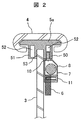
図2は、乗客コンベア1におけるハンドレール繋ぎ部材5a及びその周辺を、乗客コンベアの進行方向と直交するように縦断面して示す部分断面図である。図3は、照明装置を乗客コンベアの欄干パネル3に取付ける工程を示す一部省略斜視図である。図2及び図3に示すように、乗客コンベア1は、欄干パネル3の周辺を照らす照明灯8と、照明灯8を保持するための照明灯保持部材7と、照明灯8をカバーするための照明灯カバー部材6と、を備える。
FIG. 2 is a partial cross-sectional view showing the
ハンドレールガイド5´のガイド部材5及び各ガイド部材5,5間の繋ぎ部材(ハンドレールガイド繋ぎ部材)5aは、アルミニウム材等の加工容易な適宜な金属材料、或いは合成樹脂により加工成形され、図2に示すように、欄干パネル3の上縁に嵌合する断面U字型の嵌合溝53と、嵌合溝53を形成する左右の二重壁体50、51を有する。各二重壁体50、51は、空洞52を有する。
The guide member 5 of the handrail guide 5 ′ and the connecting member (handrail guide connecting member) 5 a between the guide members 5, 5 are processed and formed of an appropriate metal material that is easy to process such as an aluminum material, or a synthetic resin, As shown in FIG. 2, it has a
照明灯保持部材7及び照明灯カバー部材6は、ハンドレールガイド繋ぎ部材5aに固定支持されて、ハンドレールガイド繋ぎ部材5aと共に、一つの組立体としてユニット化され、このユニットにより照明装置が構成されている。
The illuminating
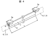
照明灯保持部材7は、図1、図3及び図4(図4は、照明灯保持部材7と照明灯カバー部材6とハンドレールガイド繋ぎ部材5aとを一つの組立体としてユニット化した状態の部分斜視図である)に示すように、欄干パネル3の継目30間のスパンLに合わせた長さのものが複数使用される。これらの照明灯保持部材7同士がハンドレールガイド繋ぎ部材5aを介して一続きに連結されている。
1, 3 and 4 (FIG. 4 shows a state in which the illumination
各照明灯保持部材7は、例えば透明或いは半透明の材質により筒状に形成され、図2に示すように長手方向の各端部側が、ハンドレールガイド繋ぎ部材5aの壁体50の下端に螺子10を介して支持されている。さらに、照明灯カバー部材6は、螺子11を介して、照明灯保持部材7の下端に支持されている。すなわち、壁体50の下端となる底壁には、螺子穴が設けられ、また、照明灯保持部材7の上壁にも螺子穴が設けられ、これらの螺子穴に螺子10を通すことで、照明灯保持部材7がハンドレールガイド繋ぎ部材5aの下端に吊り下がるようにして装着される。この螺子10を螺子穴に通す場合には、照明灯8及び照明灯カバー部材6を照明灯保持部材7に装着する前に行われる。すなわち、照明灯8及び照明灯カバー部材6を照明灯保持部材7に装着する前に、照明灯保持部材7の底部の一部が開放されるので、この開放された底部を介して、螺子10が照明灯保持部材7の上壁と壁体50の下端に設けた螺子穴に通される。
Each illumination
照明灯カバー部材6は、透明な帯板で構成され、照明灯保持部材7から下方に向けて突出するようにして、照明灯保持部材7に螺子11により取付けられる。例えば、照明灯保持部材7の一側面の下部と照明灯カバー部材6の上部とに横方向から螺子11を受け入れる螺子穴が設けられ、この螺子穴を通して螺子11を通すことで、照明灯カバー部材6が照明灯保持部材7に取付けられる。照明灯カバー部材6は、照明灯保持部材7の底部を塞ぎ且つ照明灯保持部材7の下端から下方に向けて吊り下がるようにして取付けられる。照明灯保持部材7と照明灯カバー部材6とは、欄干パネル3の内側、すなわち搬送帯側に臨むように、ハンドレールガイド継ぎ部材5aの壁体50に取付けられる。
The illuminating
照明灯カバー部材6は、照明灯保持部材7の数に合わせて複数配置される。照明灯保持部材7とそれに対応するそれぞれの照明灯カバー部材6とによって、ハンドレールガイド5´の長手方向に沿って配置される管状の照明灯8を受け入れる筒状のスペースが形成される。照明灯カバー部材6は、例えば透明なアクリル板よりなり、照明灯8の光は、この照明灯カバー部材6を介して欄干パネル3の周辺を照らす。
A plurality of illumination
本実施例における管状の照明灯8は、例えば可撓性を有する透明な長尺の樹脂チューブ内にLEDを配列してなるLEDチューブライト或いは蛍光管が用いられる。図3は、照明灯8としてLEDチューブライトを使用する場合における、乗客コンベアへの照明装置の取付け方法の一例を示す。
As the
図3の例では、欄干パネル3にハンドレールガイド繋ぎ部材5aを取付ける前に、各ガイド部材5が欄干パネル3に取付けられる。また、ハンドレールガイド繋ぎ部材5aを取付ける前に、照明灯保持部材7と照明灯カバー部材6とハンドレールガイド繋ぎ部材5aとを、上記した螺子10、11を介して一つの照明装置組立体としてユニット化する。このユニット化の工程において、照明灯(LEDチューブライト)8が照明灯保持部材7と照明灯カバー部材6とで形成される筒状スペース内に挿入する。この工程後に、ハンドレールガイド繋ぎ部材5aを各ガイド部材5,5間に挿入して欄干パネル3の上縁に嵌合することで、ハンドレールガイド繋ぎ部材5aと共に照明灯保持部材7及び照明灯カバー部材6が欄干パネル3に取付けられる(ユニット装着工程)。
In the example of FIG. 3, each guide member 5 is attached to the
かような照明装置取付け方法によれば、乗客コンベア1の欄干パネル3に照明装置を取付ける場合に、照明灯保持部材7と照明灯カバー部材6とハンドレールガイド繋ぎ部材5aとを予め一つの組立体としてユニット化しておくことで、ハンドレールガイド繋ぎ部材5aをハンドレールガイド5´の各ガイド部材5,5間に挿入して欄干パネル3の上縁に嵌合すれば、それに伴って、照明灯保持部材7と照明灯カバー部材6とが自ずと欄干パネル3に装着される。また、照明装置を欄干パネルから取り外す場合にも、ハンドレールガイドの大部分(ガイド部材5)を残した状態で、その一部であるハンドレールガイド繋ぎ部材5aを欄干パネル3から取り外せば、それに伴い照明灯保持部材7と照明灯カバー部材6とが欄干パネル3から外れることになる。
According to such an illuminating device mounting method, when the illuminating device is attached to the
したがって、本実施例によれば、照明装置を、新設及び保守のいずれの場合であっても、重量的な作業負担の軽減を図りつつ、容易に乗客コンベア1に着脱することができる。 Therefore, according to the present embodiment, the lighting device can be easily attached to and detached from the passenger conveyor 1 while reducing the heavy work load in both cases of new installation and maintenance.
また、必要に応じて、ハンドレールガイド繋ぎ部材5aを欄干パネル3に取付けた状態で、照明灯保持部材7をハンドレールガイド部材6に、照明灯カバー部材6を照明灯保持部材7に、それぞれ螺子等の適宜固着手段を介して着脱することも可能であり、照明装置部品の部分的な交換も可能となる。
If necessary, with the handrail
さらに、本実施例に係るハンドレールガイド繋ぎ部材5aは、図7に示すような照明装置の無い既設の乗客コンベアのハンドレールガイド繋ぎ部材5aに対して、互換性のある構造を有することで、ハンドレールガイド繋ぎ部材5aを既設のものから本実施例に係るものに交換するだけで、照明灯保持部材7と照明灯カバー部材6とが既設の乗客コンベアに後付けで装着することが可能となる。すなわち、既設の照明装置無しの乗客コンベアに照明装置を後付けする場合には、それぞれのガイド部材5を欄干パネル3に残した状態で、それらの間にある元のハンドレールガイド繋ぎ部材5aを、ユニット化された新たな照明装置付きハンドレールガイド繋ぎ部材5aと入れ替えて行う。
Furthermore, the handrail
なお、照明灯保持部材7と照明灯カバー部材6は、それぞれが個別にハンドレールガイド繋ぎ部材5aに着脱することも可能であり、これらの部材の部分的交換も可能である。
The illuminating
上記実施例において、照明灯8をLEDチューブライトで構成した場合には、各欄干パネル3における全体の照明灯8を一続きの長尺ライトで構成できるので、その電源供給端子の数や設置態様を複数の蛍光管よりも簡単な構造にすることができる。電源供給端子は、図示省略されているが、ユニット化された照明装置の組立体の両端に設けられる。
In the said Example, when the illuminating
図5は、本発明の他の実施例(第2実施例)の乗客コンベア(エスカレーター)に用いる照明装置を、乗客コンベアの欄干パネルに取付ける工程を示す一部省略斜視図である。
本実施例でも、乗客コンベアの一実施例としてエスカレーターを例示する。本実施例と第1実施例との相違点は、照明灯にあり、それ以外については、第1実施例と同様の構成をなす。本実施例では、照明灯8として、複数の蛍光管81を使用し、各蛍光管81は各ハンドレール繋ぎ部材5a,5a間の照明灯保持部材7に収まる長さを有している。また、各照明灯保持部材7には、蛍光管のソケット80が設けられている。
FIG. 5 is a partially omitted perspective view showing a step of attaching a lighting device used in a passenger conveyor (escalator) of another embodiment (second embodiment) of the present invention to a balustrade panel of the passenger conveyor.
Also in this embodiment, an escalator is illustrated as an example of a passenger conveyor. The difference between the present embodiment and the first embodiment lies in the illuminating lamp, and otherwise the configuration is the same as that of the first embodiment. In this embodiment, a plurality of
図6は、本発明の他の実施例(第3実施例)の乗客コンベア(エスカレーター)における欄干装置付近を示す縦断面図である。 FIG. 6 is a longitudinal sectional view showing the vicinity of a balustrade apparatus in a passenger conveyor (escalator) of another embodiment (third embodiment) of the present invention.
本実施例でも、乗客コンベアの一実施例としてエスカレーターを例示する。本実施例と第1実施例との相違点は、照明灯にあり、それ以外については、第1実施例と同様の構成をなす。本実施例では、照明灯8として、複数のLED9を使用し、これらのLED9が照明灯保持部材7と照明灯カバー部材6とで形成される筒状のスペースの長手方向に適宜の間隔で配置されている。LED9から発する光は、照明灯カバー6を通しハンドレールガイド5付近で連続体となって光り見える。
Also in this embodiment, an escalator is illustrated as an example of a passenger conveyor. The difference between the present embodiment and the first embodiment lies in the illuminating lamp, and otherwise the configuration is the same as that of the first embodiment. In this embodiment, a plurality of
なお、上記実施例に適用される照明装置は、エスカレーターに限らず、可動搬送帯が無端状に連結される複数のパレットにより構成される動く歩道などについても適用できる。 In addition, the illuminating device applied to the said Example is applicable not only to an escalator but the moving walk etc. which are comprised with several pallets to which a movable conveyance belt | band | zone is connected endlessly.
1…乗客コンベア 2…ステップ、3…欄干、4…ハンドレール、5…ハンドレールガイド、5a…ハンドレールガイド繋ぎ部材、6…照明灯カバー、7…照明灯保持部材、8…照明灯。
DESCRIPTION OF SYMBOLS 1 ...
Claims (13)
前記可動搬送帯と同期して移動するハンドレールと、
前記可動搬送帯の左右両側に配置される欄干パネルと、
前記ハンドレールの移動を案内するために前記欄干パネルの上縁に固定配置されるハンドレールガイドと、
前記ハンドレールガイドの要素となる複数のガイド部材の繋ぎとして、各ガイド部材間にあって前記欄干パネルの上縁に取付けられるハンドレールガイド繋ぎ部材と、
前記欄干パネルの周辺を照らす照明灯と、
前記照明灯を保持する照明灯保持部材と、
前記照明灯をカバーする照明灯カバー部材と、を備え、
前記照明灯保持部材及び前記照明灯カバー部材は、前記ハンドレールガイド繋ぎ部材に固定支持されて、前記ハンドレールガイド繋ぎ部材を介して、該ハンドレールガイド繋ぎ部材と一体に及び該ハンドレールガイド繋ぎ部材と別々のいずれによっても、前記欄干パネルに着脱し得る構成をなしていることを特徴とする照明装置付き乗客コンベア。 An endless movable transport belt that carries passengers and travels along the movement path;
A handrail that moves in synchronization with the movable transport zone;
Balustrade panels arranged on both the left and right sides of the movable transport belt;
A handrail guide fixedly disposed on the upper edge of the balustrade panel to guide the movement of the handrail;
As a connection of a plurality of guide members that are elements of the hand rail guide, a hand rail guide connection member that is attached to the upper edge of the balustrade panel between the guide members,
An illumination light illuminating the periphery of the balustrade panel;
An illumination lamp holding member that holds the illumination lamp;
An illumination light cover member that covers the illumination light, and
The illuminating lamp holding member and the illuminating lamp cover member are fixedly supported by the handrail guide connecting member, and are integrated with the handrail guide connecting member via the handrail guide connecting member and the handrail guide connecting member. A passenger conveyor with a lighting device characterized in that it can be attached to and detached from the balustrade panel by any of the members and separate members.
前記照明灯保持部材と前記照明灯カバー部材は、前記ハンドレールガイド繋ぎ部材の下端から吊り下がって前記欄干パネルのパネル面に沿って、前記嵌合溝を形成する壁体の下端に取付けられている請求項1又は2記載の照明装置付き乗客コンベア。 The handrail guide connecting member is provided with a fitting groove for fitting to the upper edge of the balustrade panel,
The illuminating lamp holding member and the illuminating lamp cover member are attached to the lower end of the wall body that hangs from the lower end of the handrail guide connecting member and forms the fitting groove along the panel surface of the balustrade panel. The passenger conveyor with a lighting device according to claim 1 or 2.
前記照明灯カバー部材は、螺子を介して、前記照明灯保持部材の下端に支持されている請求項3記載の照明装置付き乗客コンベア。 The illuminating lamp holding member is supported on the lower end of the wall body via a screw,
4. The passenger conveyor with illumination device according to claim 3, wherein the illumination light cover member is supported by a lower end of the illumination light holding member via a screw.
前記照明灯保持部材は、前記欄干パネルの継目間のスパンに合わせた長さを有して複数配置され、これらの照明灯保持部材同士が前記ハンドレールガイド繋ぎ部材を介して一連に接続され、
前記照明灯カバー部材は、前記照明灯保持部材の数に合わせて複数配置され、それぞれが透明な帯板で構成され、且つ前記照明灯保持部材から下方に向けて突出して前記照明灯保持部材に取付けられ、
これらの照明灯保持部材とそれに対応するそれぞれの照明灯カバー部材とによって、前記ハンドレールガイドの長手方向に沿って配置される管状の照明灯或いは複数のLED照明を受け入れる筒状のスペースが形成されている請求項1ないし4のいずれか1項記載の照明装置付き乗客コンベア。 The balustrade panel is configured by joining together a plurality of panel members, and the handrail guide connecting members are arranged in a plurality so as to be located at the joints between the balustrade panels,
A plurality of the lamp holders are arranged to have a length according to the span between the joints of the balustrade panel, and these lamp holders are connected in series via the handrail guide connecting member,
A plurality of the illuminating lamp cover members are arranged in accordance with the number of the illuminating lamp holding members, each is formed of a transparent strip, and protrudes downward from the illuminating lamp holding member to the illuminating lamp holding member. Installed and
The illuminating lamp holding members and the corresponding illuminating lamp cover members form a tubular illuminating lamp or a cylindrical space for receiving a plurality of LED lights arranged along the longitudinal direction of the handrail guide. The passenger conveyor with a lighting device according to any one of claims 1 to 4.
前記ハンドレールガイドの要素となる複数のガイド部材の繋ぎとして、各ガイド部材間をうめるように前記乗客コンベアの欄干パネルの上縁に取付けられる構造を有するハンドレールガイド繋ぎ部材と、
乗客コンベアの欄干パネルの周辺を照らす照明灯を保持するための照明灯保持部材と、
前記照明灯をカバーする照明灯カバー部材と、を含み、
前記照明灯保持部材と前記照明灯カバー部材は、前記ハンドレールガイド繋ぎ部材と共に一つの組立体としてユニット化されて、前記ハンドレールガイド繋ぎ部材を介して、該ハンドレールガイド繋ぎ部材と一体に及び該ハンドレールガイド繋ぎ部材と別々のいずれによっても、前記欄干パネルに着脱し得る構成をなしていることを特徴とする乗客コンベア用の照明装置。 An endless movable transport belt that travels on a moving path with passengers on it, a handrail that moves in synchronization with the movable transport belt, a balustrade panel that is disposed on the left and right sides of the movable transport belt, A handrail guide fixedly arranged on the upper edge of the balustrade panel to guide movement, and a lighting device applied to a passenger conveyor,
As a connection of a plurality of guide members serving as elements of the handrail guide, a handrail guide connection member having a structure attached to the upper edge of the balustrade panel of the passenger conveyor so as to fill between the guide members,
An illumination lamp holding member for holding an illumination lamp that illuminates the periphery of the balustrade panel of the passenger conveyor;
An illumination lamp cover member that covers the illumination lamp, and
The illuminating lamp holding member and the illuminating lamp cover member are unitized as an assembly together with the handrail guide connecting member, and are integrated with the handrail guide connecting member via the handrail guide connecting member. An illuminating device for a passenger conveyor, which is configured to be detachable from the balustrade panel by any of the handrail guide connecting members.
前記照明灯保持部材及び前記照明灯カバー部材は、前記ハンドレールガイド繋ぎ部材が前記欄干パネルへ取付けられると、前記欄干パネルのパネル面に沿って位置するよう構成されている請求項6又は7記載の乗客コンベア用の照明装置。 The handrail guide connecting member has a structure that is attached to the upper edge of the balustrade panel at a position between the guide members by fitting,
The said illumination light holding member and the said illumination light cover member are comprised so that it may be located along the panel surface of the said balustrade panel, when the said handrail guide connection member is attached to the said balustrade panel. Lighting equipment for passenger conveyors.
前記照明灯カバー部材は、螺子を介して、前記照明灯保持部材の下端に支持されている請求項9記載の乗客コンベア用の照明装置。 The illuminating lamp holding member is supported on the lower end of the wall body via a screw,
The illumination device for a passenger conveyor according to claim 9, wherein the illumination lamp cover member is supported by a lower end of the illumination lamp holding member via a screw.
前記照明灯カバー部材は、前記照明灯保持部材の数に合わせて複数配置され、それぞれが透明な帯板で構成され、且つ前記照明灯保持部材から下方に向けて突出するようにして、前記照明灯保持部材に取付けられ、
これらの照明灯保持部材とそれに対応するそれぞれの照明灯カバー部材とによって、管状の照明灯或いは複数のLED照明を受け入れる筒状のスペースが形成されている請求項6ないし10のいずれか1項記載の乗客コンベア用の照明装置。 The lighting lamp holding members are arranged in a plurality of lengths according to the span between seams of the balustrade panel, and these lighting lamp holding members are connected in series via the handrail guide connecting member,
A plurality of the illumination lamp cover members are arranged according to the number of the illumination lamp holding members, each of which is formed of a transparent strip, and protrudes downward from the illumination lamp holding member, so that the illumination Attached to the lamp holder,
11. A tubular space for receiving a tubular illuminating lamp or a plurality of LED lights is formed by these illuminating lamp holding members and the corresponding illuminating lamp cover members, respectively. Lighting equipment for passenger conveyors.
前記欄干パネルの周辺を照らすための照明灯を保持する照明灯保持部材と前記照明灯をカバーするための照明灯カバー部材とを、前記欄干パネルに装着する前に、前記ハンドレールガイド繋ぎ部材に取付けて前記照明灯保持部材と前記照明灯カバー部材と前記ハンドレールガイド繋ぎ部材とをユニット化するユニット組立工程と、
前記ユニット組立工程後に、前記ハンドレールガイド繋ぎ部材を前記各ガイド部材間に挿入して前記欄干パネルの上縁に嵌合することで、該ハンドレールガイド繋ぎ部材と共に前記照明灯保持部材及び前記照明灯カバー部材を前記欄干パネルに装着するユニット装着工程と、
を有することを特徴とする乗客コンベアの照明装置取付け方法。 An endless movable transport belt that travels on a moving path with passengers on it, a handrail that moves in synchronization with the movable transport belt, a balustrade panel that is disposed on the left and right sides of the movable transport belt, As a connection between a handrail guide fixedly arranged on the upper edge of the balustrade panel to guide the movement and a plurality of guide members which are elements of the handrail guide, between the guide members and on the upper edge of the balustrade panel In a method of attaching a lighting device to a passenger conveyor comprising:
An illuminating lamp holding member for holding an illuminating lamp for illuminating the periphery of the balustrade panel and an illuminating lamp cover member for covering the illuminating lamp are attached to the handrail guide connecting member before being attached to the balustrade panel. A unit assembly step of attaching and unitizing the illuminating lamp holding member, the illuminating lamp cover member, and the handrail guide connecting member;
After the unit assembling step, the handrail guide connecting member is inserted between the guide members and fitted to the upper edge of the balustrade panel, so that the illumination lamp holding member and the illumination are together with the handrail guide connecting member. A unit mounting step of mounting a lamp cover member on the balustrade panel;
A lighting device mounting method for a passenger conveyor.
前記ユニット装着工程は、前記ガイド部材を前記欄干パネルに残した状態で、それらの間にある元のハンドレールガイド繋ぎ部材を、ユニット化された前記照明装置のハンドレールガイド繋ぎ部材と入れ替えて行うことを特徴とする請求項12記載の乗客コンベアの照明装置取付け方法。 The passenger conveyor to which the lighting device is to be attached is an existing renewal target passenger conveyor that originally has no lighting device, and the unitized handrail guide connecting member of the lighting device is an element of the passenger conveyor. Make the structure compatible with the handrail guide connecting member of
The unit mounting step is performed by replacing the original handrail guide connecting member between them with the handrail guide connecting member of the unitized lighting device in a state where the guide member is left on the balustrade panel. The lighting device mounting method for a passenger conveyor according to claim 12.
Priority Applications (2)
| Application Number | Priority Date | Filing Date | Title |
|---|---|---|---|
| JP2012208452A JP5789579B2 (en) | 2012-09-21 | 2012-09-21 | Passenger conveyor with lighting device, lighting device and lighting device mounting method |
| CN201310341614.1A CN103663073B (en) | 2012-09-21 | 2013-08-07 | The subsidiary apparatus of passenger conveyor of lighting device, its lighting device and the installation method of lighting device |
Applications Claiming Priority (1)
| Application Number | Priority Date | Filing Date | Title |
|---|---|---|---|
| JP2012208452A JP5789579B2 (en) | 2012-09-21 | 2012-09-21 | Passenger conveyor with lighting device, lighting device and lighting device mounting method |
Publications (2)
| Publication Number | Publication Date |
|---|---|
| JP2014061981A true JP2014061981A (en) | 2014-04-10 |
| JP5789579B2 JP5789579B2 (en) | 2015-10-07 |
Family
ID=50302009
Family Applications (1)
| Application Number | Title | Priority Date | Filing Date |
|---|---|---|---|
| JP2012208452A Active JP5789579B2 (en) | 2012-09-21 | 2012-09-21 | Passenger conveyor with lighting device, lighting device and lighting device mounting method |
Country Status (2)
| Country | Link |
|---|---|
| JP (1) | JP5789579B2 (en) |
| CN (1) | CN103663073B (en) |
Cited By (4)
| Publication number | Priority date | Publication date | Assignee | Title |
|---|---|---|---|---|
| JP6370011B1 (en) * | 2017-06-08 | 2018-08-08 | 東芝エレベータ株式会社 | Passenger conveyor manufacturing method |
| CN109202396A (en) * | 2018-08-30 | 2019-01-15 | 安徽路明光电科技有限公司 | Material conveying device is locked out in a kind of automation LED lamp holder automatic feed of induction type |
| CN109317953A (en) * | 2018-08-30 | 2019-02-12 | 安徽路明光电科技有限公司 | A kind of LED lamp holder conveys discharging with fixed device automatically |
| JP2021011360A (en) * | 2019-07-08 | 2021-02-04 | 東芝エレベータ株式会社 | Passenger conveyor |
Families Citing this family (2)
| Publication number | Priority date | Publication date | Assignee | Title |
|---|---|---|---|---|
| CN108584658B (en) * | 2018-07-10 | 2020-03-20 | 湖州德玛吉电梯有限公司 | Escalator glass protective wall plate positioning device |
| CN109516357B (en) * | 2018-12-06 | 2023-08-18 | 金螳螂精装科技(苏州)有限公司 | Detachable aluminum plate overhauls device |
Citations (4)
| Publication number | Priority date | Publication date | Assignee | Title |
|---|---|---|---|---|
| JPS5875275U (en) * | 1981-11-16 | 1983-05-21 | 三菱電機株式会社 | passenger conveyor railing |
| JPS62161692A (en) * | 1986-01-10 | 1987-07-17 | 株式会社日立製作所 | Handrail for passenger conveyor |
| JPH0210380U (en) * | 1988-06-30 | 1990-01-23 | ||
| JP2003335490A (en) * | 2002-05-17 | 2003-11-25 | Toshiba Elevator Co Ltd | Man conveyor with handrail illuminating device |
Family Cites Families (4)
| Publication number | Priority date | Publication date | Assignee | Title |
|---|---|---|---|---|
| JP2005212977A (en) * | 2004-01-30 | 2005-08-11 | Hitachi Ltd | Passenger conveyer |
| CN2797312Y (en) * | 2005-05-25 | 2006-07-19 | 苏州江南嘉捷电梯有限公司 | Lighting device of handrail |
| CN101532616A (en) * | 2008-03-13 | 2009-09-16 | 上海爱登堡电梯有限公司 | Illuminating system of escalator |
| CN201473166U (en) * | 2009-08-20 | 2010-05-19 | 江南嘉捷电梯股份有限公司 | Handrail bracket device |
-
2012
- 2012-09-21 JP JP2012208452A patent/JP5789579B2/en active Active
-
2013
- 2013-08-07 CN CN201310341614.1A patent/CN103663073B/en active Active
Patent Citations (4)
| Publication number | Priority date | Publication date | Assignee | Title |
|---|---|---|---|---|
| JPS5875275U (en) * | 1981-11-16 | 1983-05-21 | 三菱電機株式会社 | passenger conveyor railing |
| JPS62161692A (en) * | 1986-01-10 | 1987-07-17 | 株式会社日立製作所 | Handrail for passenger conveyor |
| JPH0210380U (en) * | 1988-06-30 | 1990-01-23 | ||
| JP2003335490A (en) * | 2002-05-17 | 2003-11-25 | Toshiba Elevator Co Ltd | Man conveyor with handrail illuminating device |
Cited By (5)
| Publication number | Priority date | Publication date | Assignee | Title |
|---|---|---|---|---|
| JP6370011B1 (en) * | 2017-06-08 | 2018-08-08 | 東芝エレベータ株式会社 | Passenger conveyor manufacturing method |
| JP2018203507A (en) * | 2017-06-08 | 2018-12-27 | 東芝エレベータ株式会社 | Manufacturing method of passenger conveyor |
| CN109202396A (en) * | 2018-08-30 | 2019-01-15 | 安徽路明光电科技有限公司 | Material conveying device is locked out in a kind of automation LED lamp holder automatic feed of induction type |
| CN109317953A (en) * | 2018-08-30 | 2019-02-12 | 安徽路明光电科技有限公司 | A kind of LED lamp holder conveys discharging with fixed device automatically |
| JP2021011360A (en) * | 2019-07-08 | 2021-02-04 | 東芝エレベータ株式会社 | Passenger conveyor |
Also Published As
| Publication number | Publication date |
|---|---|
| JP5789579B2 (en) | 2015-10-07 |
| CN103663073A (en) | 2014-03-26 |
| CN103663073B (en) | 2016-08-24 |
Similar Documents
| Publication | Publication Date | Title |
|---|---|---|
| JP5789579B2 (en) | Passenger conveyor with lighting device, lighting device and lighting device mounting method | |
| JP5773862B2 (en) | Passenger conveyor | |
| JP5578895B2 (en) | Railing lighting device for passenger conveyor | |
| JP6125600B1 (en) | Passenger conveyor | |
| CN104724587B (en) | Passenger conveyer device | |
| JP6370011B1 (en) | Passenger conveyor manufacturing method | |
| JP5707620B2 (en) | Passenger conveyor | |
| JP6480855B2 (en) | Passenger conveyor | |
| WO2016020006A1 (en) | Truss construction for a passenger conveyor comprising a single wall profile | |
| JP5770003B2 (en) | Lighting equipment for passenger conveyors | |
| JP2013154998A (en) | Lighting device for passenger conveyor | |
| KR20100111830A (en) | Channel sign using extrusion bar having independent upper and lower parts | |
| JP2014012591A (en) | Luminaire for passenger conveyor | |
| JP2016055930A (en) | Passenger conveyor device | |
| JP2005212977A (en) | Passenger conveyer | |
| CN104276492A (en) | Illumination device in elevator car | |
| JP2014043305A (en) | Handrail device of passenger conveyor | |
| CN205716713U (en) | A kind of multiaspect light outlet lamp | |
| CN212559063U (en) | Passenger conveyor | |
| CN202321886U (en) | Suspended ceiling of elevator | |
| JP2014118226A (en) | Passenger conveyer handrail lighting device | |
| JP2001097659A (en) | Foot light device for passenger conveyor | |
| JP5174387B2 (en) | Passenger conveyor | |
| JPH05162965A (en) | Handrail of man conveyor | |
| WO2019244237A1 (en) | Lighting device for passenger conveyors |
Legal Events
| Date | Code | Title | Description |
|---|---|---|---|
| A621 | Written request for application examination |
Free format text: JAPANESE INTERMEDIATE CODE: A621 Effective date: 20140822 |
|
| A977 | Report on retrieval |
Free format text: JAPANESE INTERMEDIATE CODE: A971007 Effective date: 20141211 |
|
| A131 | Notification of reasons for refusal |
Free format text: JAPANESE INTERMEDIATE CODE: A131 Effective date: 20141216 |
|
| A521 | Written amendment |
Free format text: JAPANESE INTERMEDIATE CODE: A523 Effective date: 20150203 |
|
| TRDD | Decision of grant or rejection written | ||
| A01 | Written decision to grant a patent or to grant a registration (utility model) |
Free format text: JAPANESE INTERMEDIATE CODE: A01 Effective date: 20150728 |
|
| A61 | First payment of annual fees (during grant procedure) |
Free format text: JAPANESE INTERMEDIATE CODE: A61 Effective date: 20150803 |
|
| R150 | Certificate of patent or registration of utility model |
Ref document number: 5789579 Country of ref document: JP Free format text: JAPANESE INTERMEDIATE CODE: R150 |