JP2014040768A - Snow-melting solar battery panel, roof with snow-melting solar battery panel, method of manufacturing snow-melting solar battery panel, and snow-melting panel - Google Patents
Snow-melting solar battery panel, roof with snow-melting solar battery panel, method of manufacturing snow-melting solar battery panel, and snow-melting panel Download PDFInfo
- Publication number
- JP2014040768A JP2014040768A JP2013073951A JP2013073951A JP2014040768A JP 2014040768 A JP2014040768 A JP 2014040768A JP 2013073951 A JP2013073951 A JP 2013073951A JP 2013073951 A JP2013073951 A JP 2013073951A JP 2014040768 A JP2014040768 A JP 2014040768A
- Authority
- JP
- Japan
- Prior art keywords
- solar cell
- rubber sheet
- conductive rubber
- snow melting
- snow
- Prior art date
- Legal status (The legal status is an assumption and is not a legal conclusion. Google has not performed a legal analysis and makes no representation as to the accuracy of the status listed.)
- Pending
Links
- 238000002844 melting Methods 0.000 title claims abstract description 93
- 238000004519 manufacturing process Methods 0.000 title claims description 12
- 229920001971 elastomer Polymers 0.000 claims abstract description 222
- 239000005060 rubber Substances 0.000 claims abstract description 222
- 239000012857 radioactive material Substances 0.000 claims abstract description 15
- 230000008018 melting Effects 0.000 claims description 79
- 229910052751 metal Inorganic materials 0.000 claims description 29
- 239000002184 metal Substances 0.000 claims description 29
- 239000005341 toughened glass Substances 0.000 claims description 28
- 239000005413 snowmelt Substances 0.000 claims description 27
- 238000010438 heat treatment Methods 0.000 claims description 19
- 239000004711 α-olefin Substances 0.000 claims description 16
- 229920000089 Cyclic olefin copolymer Polymers 0.000 claims description 14
- 239000003431 cross linking reagent Substances 0.000 claims description 14
- 239000003566 sealing material Substances 0.000 claims description 14
- 239000000941 radioactive substance Substances 0.000 claims description 11
- 230000002093 peripheral effect Effects 0.000 claims description 9
- 150000001451 organic peroxides Chemical class 0.000 claims description 8
- 238000002156 mixing Methods 0.000 claims description 5
- 238000007789 sealing Methods 0.000 claims description 2
- 229920001967 Metal rubber Polymers 0.000 claims 1
- 238000010248 power generation Methods 0.000 abstract description 11
- 150000001993 dienes Chemical class 0.000 abstract description 7
- 238000005516 engineering process Methods 0.000 abstract description 3
- 229920001897 terpolymer Polymers 0.000 abstract description 3
- 239000010410 layer Substances 0.000 description 29
- 239000003795 chemical substances by application Substances 0.000 description 17
- 238000000034 method Methods 0.000 description 17
- 229920005989 resin Polymers 0.000 description 16
- 239000011347 resin Substances 0.000 description 16
- -1 methylene norbornene Chemical compound 0.000 description 12
- 238000009826 distribution Methods 0.000 description 10
- 229910052757 nitrogen Inorganic materials 0.000 description 10
- 229910021417 amorphous silicon Inorganic materials 0.000 description 9
- 239000011231 conductive filler Substances 0.000 description 9
- 230000000694 effects Effects 0.000 description 9
- 239000000203 mixture Substances 0.000 description 9
- 238000000465 moulding Methods 0.000 description 9
- 238000004073 vulcanization Methods 0.000 description 9
- XLYOFNOQVPJJNP-UHFFFAOYSA-N water Substances O XLYOFNOQVPJJNP-UHFFFAOYSA-N 0.000 description 9
- 229910052782 aluminium Inorganic materials 0.000 description 8
- XAGFODPZIPBFFR-UHFFFAOYSA-N aluminium Chemical compound [Al] XAGFODPZIPBFFR-UHFFFAOYSA-N 0.000 description 8
- 238000001723 curing Methods 0.000 description 8
- OKTJSMMVPCPJKN-UHFFFAOYSA-N Carbon Chemical compound [C] OKTJSMMVPCPJKN-UHFFFAOYSA-N 0.000 description 7
- NINIDFKCEFEMDL-UHFFFAOYSA-N Sulfur Chemical compound [S] NINIDFKCEFEMDL-UHFFFAOYSA-N 0.000 description 7
- AUZONCFQVSMFAP-UHFFFAOYSA-N disulfiram Chemical compound CCN(CC)C(=S)SSC(=S)N(CC)CC AUZONCFQVSMFAP-UHFFFAOYSA-N 0.000 description 7
- 239000000463 material Substances 0.000 description 7
- 229920003192 poly(bis maleimide) Polymers 0.000 description 7
- 230000002265 prevention Effects 0.000 description 7
- KUAZQDVKQLNFPE-UHFFFAOYSA-N thiram Chemical compound CN(C)C(=S)SSC(=S)N(C)C KUAZQDVKQLNFPE-UHFFFAOYSA-N 0.000 description 7
- XQUPVDVFXZDTLT-UHFFFAOYSA-N 1-[4-[[4-(2,5-dioxopyrrol-1-yl)phenyl]methyl]phenyl]pyrrole-2,5-dione Chemical class O=C1C=CC(=O)N1C(C=C1)=CC=C1CC1=CC=C(N2C(C=CC2=O)=O)C=C1 XQUPVDVFXZDTLT-UHFFFAOYSA-N 0.000 description 6
- XEEYBQQBJWHFJM-UHFFFAOYSA-N Iron Chemical compound [Fe] XEEYBQQBJWHFJM-UHFFFAOYSA-N 0.000 description 6
- 238000004132 cross linking Methods 0.000 description 6
- 238000010586 diagram Methods 0.000 description 6
- 239000011521 glass Substances 0.000 description 6
- 229910052717 sulfur Inorganic materials 0.000 description 6
- 239000011593 sulfur Substances 0.000 description 6
- 229960002447 thiram Drugs 0.000 description 6
- XLOMVQKBTHCTTD-UHFFFAOYSA-N Zinc monoxide Chemical compound [Zn]=O XLOMVQKBTHCTTD-UHFFFAOYSA-N 0.000 description 5
- 238000013329 compounding Methods 0.000 description 5
- 230000020169 heat generation Effects 0.000 description 5
- 229910044991 metal oxide Inorganic materials 0.000 description 5
- 150000004706 metal oxides Chemical class 0.000 description 5
- VNWKTOKETHGBQD-UHFFFAOYSA-N methane Chemical compound C VNWKTOKETHGBQD-UHFFFAOYSA-N 0.000 description 5
- 229920000139 polyethylene terephthalate Polymers 0.000 description 5
- 239000005020 polyethylene terephthalate Substances 0.000 description 5
- 229920000049 Carbon (fiber) Polymers 0.000 description 4
- CPLXHLVBOLITMK-UHFFFAOYSA-N Magnesium oxide Chemical compound [Mg]=O CPLXHLVBOLITMK-UHFFFAOYSA-N 0.000 description 4
- YNAVUWVOSKDBBP-UHFFFAOYSA-N Morpholine Chemical compound C1COCCN1 YNAVUWVOSKDBBP-UHFFFAOYSA-N 0.000 description 4
- PXHVJJICTQNCMI-UHFFFAOYSA-N Nickel Chemical compound [Ni] PXHVJJICTQNCMI-UHFFFAOYSA-N 0.000 description 4
- XUIMIQQOPSSXEZ-UHFFFAOYSA-N Silicon Chemical compound [Si] XUIMIQQOPSSXEZ-UHFFFAOYSA-N 0.000 description 4
- 230000003712 anti-aging effect Effects 0.000 description 4
- TZCXTZWJZNENPQ-UHFFFAOYSA-L barium sulfate Chemical compound [Ba+2].[O-]S([O-])(=O)=O TZCXTZWJZNENPQ-UHFFFAOYSA-L 0.000 description 4
- 239000004917 carbon fiber Substances 0.000 description 4
- 230000000052 comparative effect Effects 0.000 description 4
- 229920001577 copolymer Polymers 0.000 description 4
- 239000005038 ethylene vinyl acetate Substances 0.000 description 4
- 229910002804 graphite Inorganic materials 0.000 description 4
- 239000010439 graphite Substances 0.000 description 4
- 238000010030 laminating Methods 0.000 description 4
- 238000003475 lamination Methods 0.000 description 4
- 230000007774 longterm Effects 0.000 description 4
- 229910001120 nichrome Inorganic materials 0.000 description 4
- 239000003921 oil Substances 0.000 description 4
- 229920001200 poly(ethylene-vinyl acetate) Polymers 0.000 description 4
- 229910052710 silicon Inorganic materials 0.000 description 4
- 239000010703 silicon Substances 0.000 description 4
- 229920002379 silicone rubber Polymers 0.000 description 4
- 239000010454 slate Substances 0.000 description 4
- RYGMFSIKBFXOCR-UHFFFAOYSA-N Copper Chemical compound [Cu] RYGMFSIKBFXOCR-UHFFFAOYSA-N 0.000 description 3
- VGGSQFUCUMXWEO-UHFFFAOYSA-N Ethene Chemical compound C=C VGGSQFUCUMXWEO-UHFFFAOYSA-N 0.000 description 3
- 239000005977 Ethylene Substances 0.000 description 3
- VYPSYNLAJGMNEJ-UHFFFAOYSA-N Silicium dioxide Chemical compound O=[Si]=O VYPSYNLAJGMNEJ-UHFFFAOYSA-N 0.000 description 3
- 230000001133 acceleration Effects 0.000 description 3
- 239000012790 adhesive layer Substances 0.000 description 3
- 239000006229 carbon black Substances 0.000 description 3
- 235000019241 carbon black Nutrition 0.000 description 3
- 239000013078 crystal Substances 0.000 description 3
- 239000003273 ketjen black Substances 0.000 description 3
- 239000000395 magnesium oxide Substances 0.000 description 3
- 150000002978 peroxides Chemical class 0.000 description 3
- 239000000843 powder Substances 0.000 description 3
- 239000011787 zinc oxide Substances 0.000 description 3
- 235000014692 zinc oxide Nutrition 0.000 description 3
- OJOWICOBYCXEKR-APPZFPTMSA-N (1S,4R)-5-ethylidenebicyclo[2.2.1]hept-2-ene Chemical compound CC=C1C[C@@H]2C[C@@H]1C=C2 OJOWICOBYCXEKR-APPZFPTMSA-N 0.000 description 2
- VXNZUUAINFGPBY-UHFFFAOYSA-N 1-Butene Chemical compound CCC=C VXNZUUAINFGPBY-UHFFFAOYSA-N 0.000 description 2
- IPJGAEWUPXWFPL-UHFFFAOYSA-N 1-[3-(2,5-dioxopyrrol-1-yl)phenyl]pyrrole-2,5-dione Chemical compound O=C1C=CC(=O)N1C1=CC=CC(N2C(C=CC2=O)=O)=C1 IPJGAEWUPXWFPL-UHFFFAOYSA-N 0.000 description 2
- LIKMAJRDDDTEIG-UHFFFAOYSA-N 1-hexene Chemical compound CCCCC=C LIKMAJRDDDTEIG-UHFFFAOYSA-N 0.000 description 2
- HECLRDQVFMWTQS-RGOKHQFPSA-N 1755-01-7 Chemical compound C1[C@H]2[C@@H]3CC=C[C@@H]3[C@@H]1C=C2 HECLRDQVFMWTQS-RGOKHQFPSA-N 0.000 description 2
- SDJHPPZKZZWAKF-UHFFFAOYSA-N 2,3-dimethylbuta-1,3-diene Chemical compound CC(=C)C(C)=C SDJHPPZKZZWAKF-UHFFFAOYSA-N 0.000 description 2
- BUZICZZQJDLXJN-UHFFFAOYSA-N 3-azaniumyl-4-hydroxybutanoate Chemical compound OCC(N)CC(O)=O BUZICZZQJDLXJN-UHFFFAOYSA-N 0.000 description 2
- QGZKDVFQNNGYKY-UHFFFAOYSA-N Ammonia Chemical compound N QGZKDVFQNNGYKY-UHFFFAOYSA-N 0.000 description 2
- KAKZBPTYRLMSJV-UHFFFAOYSA-N Butadiene Chemical compound C=CC=C KAKZBPTYRLMSJV-UHFFFAOYSA-N 0.000 description 2
- VTYYLEPIZMXCLO-UHFFFAOYSA-L Calcium carbonate Chemical compound [Ca+2].[O-]C([O-])=O VTYYLEPIZMXCLO-UHFFFAOYSA-L 0.000 description 2
- ZRALSGWEFCBTJO-UHFFFAOYSA-N Guanidine Chemical compound NC(N)=N ZRALSGWEFCBTJO-UHFFFAOYSA-N 0.000 description 2
- 244000043261 Hevea brasiliensis Species 0.000 description 2
- RRHGJUQNOFWUDK-UHFFFAOYSA-N Isoprene Chemical compound CC(=C)C=C RRHGJUQNOFWUDK-UHFFFAOYSA-N 0.000 description 2
- BAPJBEWLBFYGME-UHFFFAOYSA-N Methyl acrylate Chemical compound COC(=O)C=C BAPJBEWLBFYGME-UHFFFAOYSA-N 0.000 description 2
- 229920000459 Nitrile rubber Polymers 0.000 description 2
- 239000005062 Polybutadiene Substances 0.000 description 2
- 239000004698 Polyethylene Substances 0.000 description 2
- 229910004298 SiO 2 Inorganic materials 0.000 description 2
- BQCADISMDOOEFD-UHFFFAOYSA-N Silver Chemical compound [Ag] BQCADISMDOOEFD-UHFFFAOYSA-N 0.000 description 2
- 229910006404 SnO 2 Inorganic materials 0.000 description 2
- PPBRXRYQALVLMV-UHFFFAOYSA-N Styrene Chemical compound C=CC1=CC=CC=C1 PPBRXRYQALVLMV-UHFFFAOYSA-N 0.000 description 2
- ATJFFYVFTNAWJD-UHFFFAOYSA-N Tin Chemical compound [Sn] ATJFFYVFTNAWJD-UHFFFAOYSA-N 0.000 description 2
- BZHJMEDXRYGGRV-UHFFFAOYSA-N Vinyl chloride Chemical compound ClC=C BZHJMEDXRYGGRV-UHFFFAOYSA-N 0.000 description 2
- 229910026551 ZrC Inorganic materials 0.000 description 2
- OTCHGXYCWNXDOA-UHFFFAOYSA-N [C].[Zr] Chemical compound [C].[Zr] OTCHGXYCWNXDOA-UHFFFAOYSA-N 0.000 description 2
- 239000000853 adhesive Substances 0.000 description 2
- 230000001070 adhesive effect Effects 0.000 description 2
- 229910045601 alloy Inorganic materials 0.000 description 2
- 239000000956 alloy Substances 0.000 description 2
- AYJRCSIUFZENHW-UHFFFAOYSA-L barium carbonate Chemical compound [Ba+2].[O-]C([O-])=O AYJRCSIUFZENHW-UHFFFAOYSA-L 0.000 description 2
- 239000002585 base Substances 0.000 description 2
- 229920005549 butyl rubber Polymers 0.000 description 2
- BRPQOXSCLDDYGP-UHFFFAOYSA-N calcium oxide Chemical compound [O-2].[Ca+2] BRPQOXSCLDDYGP-UHFFFAOYSA-N 0.000 description 2
- 239000000292 calcium oxide Substances 0.000 description 2
- ODINCKMPIJJUCX-UHFFFAOYSA-N calcium oxide Inorganic materials [Ca]=O ODINCKMPIJJUCX-UHFFFAOYSA-N 0.000 description 2
- OSGAYBCDTDRGGQ-UHFFFAOYSA-L calcium sulfate Chemical compound [Ca+2].[O-]S([O-])(=O)=O OSGAYBCDTDRGGQ-UHFFFAOYSA-L 0.000 description 2
- 239000003610 charcoal Substances 0.000 description 2
- 238000006243 chemical reaction Methods 0.000 description 2
- 150000001875 compounds Chemical class 0.000 description 2
- 229910052802 copper Inorganic materials 0.000 description 2
- 239000010949 copper Substances 0.000 description 2
- 230000007423 decrease Effects 0.000 description 2
- 239000012933 diacyl peroxide Substances 0.000 description 2
- PPQREHKVAOVYBT-UHFFFAOYSA-H dialuminum;tricarbonate Chemical compound [Al+3].[Al+3].[O-]C([O-])=O.[O-]C([O-])=O.[O-]C([O-])=O PPQREHKVAOVYBT-UHFFFAOYSA-H 0.000 description 2
- 229920005558 epichlorohydrin rubber Polymers 0.000 description 2
- 238000011156 evaluation Methods 0.000 description 2
- 239000000835 fiber Substances 0.000 description 2
- 239000010419 fine particle Substances 0.000 description 2
- 230000008014 freezing Effects 0.000 description 2
- 238000007710 freezing Methods 0.000 description 2
- 229910052742 iron Inorganic materials 0.000 description 2
- 229920003049 isoprene rubber Polymers 0.000 description 2
- 238000004898 kneading Methods 0.000 description 2
- AXZKOIWUVFPNLO-UHFFFAOYSA-N magnesium;oxygen(2-) Chemical compound [O-2].[Mg+2] AXZKOIWUVFPNLO-UHFFFAOYSA-N 0.000 description 2
- 229920003052 natural elastomer Polymers 0.000 description 2
- 229920001194 natural rubber Polymers 0.000 description 2
- 229910052759 nickel Inorganic materials 0.000 description 2
- 239000010690 paraffinic oil Substances 0.000 description 2
- YWAKXRMUMFPDSH-UHFFFAOYSA-N pentene Chemical compound CCCC=C YWAKXRMUMFPDSH-UHFFFAOYSA-N 0.000 description 2
- 229920001084 poly(chloroprene) Polymers 0.000 description 2
- 229920002857 polybutadiene Polymers 0.000 description 2
- 229920001225 polyester resin Polymers 0.000 description 2
- 239000004645 polyester resin Substances 0.000 description 2
- 229920000573 polyethylene Polymers 0.000 description 2
- 229920002620 polyvinyl fluoride Polymers 0.000 description 2
- 238000002360 preparation method Methods 0.000 description 2
- 239000012744 reinforcing agent Substances 0.000 description 2
- 238000010058 rubber compounding Methods 0.000 description 2
- 229920006395 saturated elastomer Polymers 0.000 description 2
- 239000004065 semiconductor Substances 0.000 description 2
- 239000004945 silicone rubber Substances 0.000 description 2
- 229910052709 silver Inorganic materials 0.000 description 2
- 239000004332 silver Substances 0.000 description 2
- 239000000126 substance Substances 0.000 description 2
- UMGDCJDMYOKAJW-UHFFFAOYSA-N thiourea Chemical compound NC(N)=S UMGDCJDMYOKAJW-UHFFFAOYSA-N 0.000 description 2
- 229910052718 tin Inorganic materials 0.000 description 2
- 229910052613 tourmaline Inorganic materials 0.000 description 2
- 229940070527 tourmaline Drugs 0.000 description 2
- 239000011032 tourmaline Substances 0.000 description 2
- 229910052723 transition metal Inorganic materials 0.000 description 2
- 229920002554 vinyl polymer Polymers 0.000 description 2
- RRKODOZNUZCUBN-CCAGOZQPSA-N (1z,3z)-cycloocta-1,3-diene Chemical compound C1CC\C=C/C=C\C1 RRKODOZNUZCUBN-CCAGOZQPSA-N 0.000 description 1
- KDGNCLDCOVTOCS-UHFFFAOYSA-N (2-methylpropan-2-yl)oxy propan-2-yl carbonate Chemical compound CC(C)OC(=O)OOC(C)(C)C KDGNCLDCOVTOCS-UHFFFAOYSA-N 0.000 description 1
- PRBHEGAFLDMLAL-GQCTYLIASA-N (4e)-hexa-1,4-diene Chemical compound C\C=C\CC=C PRBHEGAFLDMLAL-GQCTYLIASA-N 0.000 description 1
- RIPYNJLMMFGZSX-UHFFFAOYSA-N (5-benzoylperoxy-2,5-dimethylhexan-2-yl) benzenecarboperoxoate Chemical compound C=1C=CC=CC=1C(=O)OOC(C)(C)CCC(C)(C)OOC(=O)C1=CC=CC=C1 RIPYNJLMMFGZSX-UHFFFAOYSA-N 0.000 description 1
- PMJHHCWVYXUKFD-SNAWJCMRSA-N (E)-1,3-pentadiene Chemical compound C\C=C\C=C PMJHHCWVYXUKFD-SNAWJCMRSA-N 0.000 description 1
- UBRWPVTUQDJKCC-UHFFFAOYSA-N 1,3-bis(2-tert-butylperoxypropan-2-yl)benzene Chemical compound CC(C)(C)OOC(C)(C)C1=CC=CC(C(C)(C)OOC(C)(C)C)=C1 UBRWPVTUQDJKCC-UHFFFAOYSA-N 0.000 description 1
- UFFVWIGGYXLXPC-UHFFFAOYSA-N 1-[2-(2,5-dioxopyrrol-1-yl)phenyl]pyrrole-2,5-dione Chemical compound O=C1C=CC(=O)N1C1=CC=CC=C1N1C(=O)C=CC1=O UFFVWIGGYXLXPC-UHFFFAOYSA-N 0.000 description 1
- AQGZJQNZNONGKY-UHFFFAOYSA-N 1-[4-(2,5-dioxopyrrol-1-yl)phenyl]pyrrole-2,5-dione Chemical compound O=C1C=CC(=O)N1C1=CC=C(N2C(C=CC2=O)=O)C=C1 AQGZJQNZNONGKY-UHFFFAOYSA-N 0.000 description 1
- NOSXUFXBUISMPR-UHFFFAOYSA-N 1-tert-butylperoxyhexane Chemical compound CCCCCCOOC(C)(C)C NOSXUFXBUISMPR-UHFFFAOYSA-N 0.000 description 1
- HYZJCKYKOHLVJF-UHFFFAOYSA-N 1H-benzimidazole Chemical compound C1=CC=C2NC=NC2=C1 HYZJCKYKOHLVJF-UHFFFAOYSA-N 0.000 description 1
- ZNRLMGFXSPUZNR-UHFFFAOYSA-N 2,2,4-trimethyl-1h-quinoline Chemical compound C1=CC=C2C(C)=CC(C)(C)NC2=C1 ZNRLMGFXSPUZNR-UHFFFAOYSA-N 0.000 description 1
- BJELTSYBAHKXRW-UHFFFAOYSA-N 2,4,6-triallyloxy-1,3,5-triazine Chemical compound C=CCOC1=NC(OCC=C)=NC(OCC=C)=N1 BJELTSYBAHKXRW-UHFFFAOYSA-N 0.000 description 1
- ODBCKCWTWALFKM-UHFFFAOYSA-N 2,5-bis(tert-butylperoxy)-2,5-dimethylhex-3-yne Chemical compound CC(C)(C)OOC(C)(C)C#CC(C)(C)OOC(C)(C)C ODBCKCWTWALFKM-UHFFFAOYSA-N 0.000 description 1
- XMNIXWIUMCBBBL-UHFFFAOYSA-N 2-(2-phenylpropan-2-ylperoxy)propan-2-ylbenzene Chemical compound C=1C=CC=CC=1C(C)(C)OOC(C)(C)C1=CC=CC=C1 XMNIXWIUMCBBBL-UHFFFAOYSA-N 0.000 description 1
- RPBWMJBZQXCSFW-UHFFFAOYSA-N 2-methylpropanoyl 2-methylpropaneperoxoate Chemical compound CC(C)C(=O)OOC(=O)C(C)C RPBWMJBZQXCSFW-UHFFFAOYSA-N 0.000 description 1
- GPNYZBKIGXGYNU-UHFFFAOYSA-N 2-tert-butyl-6-[(3-tert-butyl-5-ethyl-2-hydroxyphenyl)methyl]-4-ethylphenol Chemical compound CC(C)(C)C1=CC(CC)=CC(CC=2C(=C(C=C(CC)C=2)C(C)(C)C)O)=C1O GPNYZBKIGXGYNU-UHFFFAOYSA-N 0.000 description 1
- HLBZWYXLQJQBKU-UHFFFAOYSA-N 4-(morpholin-4-yldisulfanyl)morpholine Chemical compound C1COCCN1SSN1CCOCC1 HLBZWYXLQJQBKU-UHFFFAOYSA-N 0.000 description 1
- HVCNXQOWACZAFN-UHFFFAOYSA-N 4-ethylmorpholine Chemical compound CCN1CCOCC1 HVCNXQOWACZAFN-UHFFFAOYSA-N 0.000 description 1
- ZCYVEMRRCGMTRW-UHFFFAOYSA-N 7553-56-2 Chemical compound [I] ZCYVEMRRCGMTRW-UHFFFAOYSA-N 0.000 description 1
- NLHHRLWOUZZQLW-UHFFFAOYSA-N Acrylonitrile Chemical compound C=CC#N NLHHRLWOUZZQLW-UHFFFAOYSA-N 0.000 description 1
- 229910018072 Al 2 O 3 Inorganic materials 0.000 description 1
- QYEXBYZXHDUPRC-UHFFFAOYSA-N B#[Ti]#B Chemical compound B#[Ti]#B QYEXBYZXHDUPRC-UHFFFAOYSA-N 0.000 description 1
- 239000004342 Benzoyl peroxide Substances 0.000 description 1
- OMPJBNCRMGITSC-UHFFFAOYSA-N Benzoylperoxide Chemical compound C=1C=CC=CC=1C(=O)OOC(=O)C1=CC=CC=C1 OMPJBNCRMGITSC-UHFFFAOYSA-N 0.000 description 1
- 241001474374 Blennius Species 0.000 description 1
- 229910001369 Brass Inorganic materials 0.000 description 1
- 229910000906 Bronze Inorganic materials 0.000 description 1
- VYZAMTAEIAYCRO-UHFFFAOYSA-N Chromium Chemical compound [Cr] VYZAMTAEIAYCRO-UHFFFAOYSA-N 0.000 description 1
- MQIUGAXCHLFZKX-UHFFFAOYSA-N Di-n-octyl phthalate Natural products CCCCCCCCOC(=O)C1=CC=CC=C1C(=O)OCCCCCCCC MQIUGAXCHLFZKX-UHFFFAOYSA-N 0.000 description 1
- JIGUQPWFLRLWPJ-UHFFFAOYSA-N Ethyl acrylate Chemical compound CCOC(=O)C=C JIGUQPWFLRLWPJ-UHFFFAOYSA-N 0.000 description 1
- 229910001218 Gallium arsenide Inorganic materials 0.000 description 1
- 101000581533 Homo sapiens Methylcrotonoyl-CoA carboxylase beta chain, mitochondrial Proteins 0.000 description 1
- 239000005909 Kieselgur Substances 0.000 description 1
- VVQNEPGJFQJSBK-UHFFFAOYSA-N Methyl methacrylate Chemical compound COC(=O)C(C)=C VVQNEPGJFQJSBK-UHFFFAOYSA-N 0.000 description 1
- 102100027320 Methylcrotonoyl-CoA carboxylase beta chain, mitochondrial Human genes 0.000 description 1
- OUBMGJOQLXMSNT-UHFFFAOYSA-N N-isopropyl-N'-phenyl-p-phenylenediamine Chemical compound C1=CC(NC(C)C)=CC=C1NC1=CC=CC=C1 OUBMGJOQLXMSNT-UHFFFAOYSA-N 0.000 description 1
- CHJJGSNFBQVOTG-UHFFFAOYSA-N N-methyl-guanidine Natural products CNC(N)=N CHJJGSNFBQVOTG-UHFFFAOYSA-N 0.000 description 1
- 229910052779 Neodymium Inorganic materials 0.000 description 1
- 239000002033 PVDF binder Substances 0.000 description 1
- ISWSIDIOOBJBQZ-UHFFFAOYSA-N Phenol Chemical compound OC1=CC=CC=C1 ISWSIDIOOBJBQZ-UHFFFAOYSA-N 0.000 description 1
- 239000004793 Polystyrene Substances 0.000 description 1
- 239000004115 Sodium Silicate Substances 0.000 description 1
- 229910000831 Steel Inorganic materials 0.000 description 1
- 239000004830 Super Glue Substances 0.000 description 1
- FZWLAAWBMGSTSO-UHFFFAOYSA-N Thiazole Chemical compound C1=CSC=N1 FZWLAAWBMGSTSO-UHFFFAOYSA-N 0.000 description 1
- 229910034327 TiC Inorganic materials 0.000 description 1
- 229910010413 TiO 2 Inorganic materials 0.000 description 1
- RTAQQCXQSZGOHL-UHFFFAOYSA-N Titanium Chemical compound [Ti] RTAQQCXQSZGOHL-UHFFFAOYSA-N 0.000 description 1
- NRTOMJZYCJJWKI-UHFFFAOYSA-N Titanium nitride Chemical compound [Ti]#N NRTOMJZYCJJWKI-UHFFFAOYSA-N 0.000 description 1
- OKKRPWIIYQTPQF-UHFFFAOYSA-N Trimethylolpropane trimethacrylate Chemical compound CC(=C)C(=O)OCC(CC)(COC(=O)C(C)=C)COC(=O)C(C)=C OKKRPWIIYQTPQF-UHFFFAOYSA-N 0.000 description 1
- XSQUKJJJFZCRTK-UHFFFAOYSA-N Urea Natural products NC(N)=O XSQUKJJJFZCRTK-UHFFFAOYSA-N 0.000 description 1
- 229920006311 Urethane elastomer Polymers 0.000 description 1
- HCHKCACWOHOZIP-UHFFFAOYSA-N Zinc Chemical compound [Zn] HCHKCACWOHOZIP-UHFFFAOYSA-N 0.000 description 1
- 239000005083 Zinc sulfide Substances 0.000 description 1
- QCWXUUIWCKQGHC-UHFFFAOYSA-N Zirconium Chemical compound [Zr] QCWXUUIWCKQGHC-UHFFFAOYSA-N 0.000 description 1
- GEIAQOFPUVMAGM-UHFFFAOYSA-N ZrO Inorganic materials [Zr]=O GEIAQOFPUVMAGM-UHFFFAOYSA-N 0.000 description 1
- 229910006501 ZrSiO Inorganic materials 0.000 description 1
- WMVSVUVZSYRWIY-UHFFFAOYSA-N [(4-benzoyloxyiminocyclohexa-2,5-dien-1-ylidene)amino] benzoate Chemical compound C=1C=CC=CC=1C(=O)ON=C(C=C1)C=CC1=NOC(=O)C1=CC=CC=C1 WMVSVUVZSYRWIY-UHFFFAOYSA-N 0.000 description 1
- MUBKMWFYVHYZAI-UHFFFAOYSA-N [Al].[Cu].[Zn] Chemical compound [Al].[Cu].[Zn] MUBKMWFYVHYZAI-UHFFFAOYSA-N 0.000 description 1
- YKTSYUJCYHOUJP-UHFFFAOYSA-N [O--].[Al+3].[Al+3].[O-][Si]([O-])([O-])[O-] Chemical compound [O--].[Al+3].[Al+3].[O-][Si]([O-])([O-])[O-] YKTSYUJCYHOUJP-UHFFFAOYSA-N 0.000 description 1
- 238000009825 accumulation Methods 0.000 description 1
- 239000006230 acetylene black Substances 0.000 description 1
- 125000005396 acrylic acid ester group Chemical group 0.000 description 1
- 239000002671 adjuvant Substances 0.000 description 1
- 150000001299 aldehydes Chemical class 0.000 description 1
- 229910000272 alkali metal oxide Inorganic materials 0.000 description 1
- 229910000287 alkaline earth metal oxide Inorganic materials 0.000 description 1
- XYLMUPLGERFSHI-UHFFFAOYSA-N alpha-Methylstyrene Chemical compound CC(=C)C1=CC=CC=C1 XYLMUPLGERFSHI-UHFFFAOYSA-N 0.000 description 1
- HSFWRNGVRCDJHI-UHFFFAOYSA-N alpha-acetylene Natural products C#C HSFWRNGVRCDJHI-UHFFFAOYSA-N 0.000 description 1
- WNROFYMDJYEPJX-UHFFFAOYSA-K aluminium hydroxide Chemical compound [OH-].[OH-].[OH-].[Al+3] WNROFYMDJYEPJX-UHFFFAOYSA-K 0.000 description 1
- 229940118662 aluminum carbonate Drugs 0.000 description 1
- 150000001412 amines Chemical class 0.000 description 1
- 229910021529 ammonia Inorganic materials 0.000 description 1
- 239000010692 aromatic oil Substances 0.000 description 1
- 239000010425 asbestos Substances 0.000 description 1
- CFJRGWXELQQLSA-UHFFFAOYSA-N azanylidyneniobium Chemical compound [Nb]#N CFJRGWXELQQLSA-UHFFFAOYSA-N 0.000 description 1
- 235000019400 benzoyl peroxide Nutrition 0.000 description 1
- 229910002056 binary alloy Inorganic materials 0.000 description 1
- BJQHLKABXJIVAM-UHFFFAOYSA-N bis(2-ethylhexyl) phthalate Chemical compound CCCCC(CC)COC(=O)C1=CC=CC=C1C(=O)OCC(CC)CCCC BJQHLKABXJIVAM-UHFFFAOYSA-N 0.000 description 1
- 239000010951 brass Substances 0.000 description 1
- 239000010974 bronze Substances 0.000 description 1
- 229910000019 calcium carbonate Inorganic materials 0.000 description 1
- WUKWITHWXAAZEY-UHFFFAOYSA-L calcium difluoride Chemical compound [F-].[F-].[Ca+2] WUKWITHWXAAZEY-UHFFFAOYSA-L 0.000 description 1
- 229910001634 calcium fluoride Inorganic materials 0.000 description 1
- 239000000378 calcium silicate Substances 0.000 description 1
- 229910052918 calcium silicate Inorganic materials 0.000 description 1
- OYACROKNLOSFPA-UHFFFAOYSA-N calcium;dioxido(oxo)silane Chemical compound [Ca+2].[O-][Si]([O-])=O OYACROKNLOSFPA-UHFFFAOYSA-N 0.000 description 1
- DKVNPHBNOWQYFE-UHFFFAOYSA-N carbamodithioic acid Chemical compound NC(S)=S DKVNPHBNOWQYFE-UHFFFAOYSA-N 0.000 description 1
- 229910052799 carbon Inorganic materials 0.000 description 1
- 125000004432 carbon atom Chemical group C* 0.000 description 1
- 239000002134 carbon nanofiber Substances 0.000 description 1
- 150000004649 carbonic acid derivatives Chemical class 0.000 description 1
- 239000004203 carnauba wax Substances 0.000 description 1
- 235000013869 carnauba wax Nutrition 0.000 description 1
- 239000000919 ceramic Substances 0.000 description 1
- 239000003086 colorant Substances 0.000 description 1
- 239000002131 composite material Substances 0.000 description 1
- 239000000470 constituent Substances 0.000 description 1
- 238000010276 construction Methods 0.000 description 1
- 239000011889 copper foil Substances 0.000 description 1
- KUNSUQLRTQLHQQ-UHFFFAOYSA-N copper tin Chemical compound [Cu].[Sn] KUNSUQLRTQLHQQ-UHFFFAOYSA-N 0.000 description 1
- 229910052878 cordierite Inorganic materials 0.000 description 1
- LSXWFXONGKSEMY-UHFFFAOYSA-N di-tert-butyl peroxide Chemical compound CC(C)(C)OOC(C)(C)C LSXWFXONGKSEMY-UHFFFAOYSA-N 0.000 description 1
- WITDFSFZHZYQHB-UHFFFAOYSA-N dibenzylcarbamothioylsulfanyl n,n-dibenzylcarbamodithioate Chemical compound C=1C=CC=CC=1CN(CC=1C=CC=CC=1)C(=S)SSC(=S)N(CC=1C=CC=CC=1)CC1=CC=CC=C1 WITDFSFZHZYQHB-UHFFFAOYSA-N 0.000 description 1
- PGAXJQVAHDTGBB-UHFFFAOYSA-N dibutylcarbamothioylsulfanyl n,n-dibutylcarbamodithioate Chemical compound CCCCN(CCCC)C(=S)SSC(=S)N(CCCC)CCCC PGAXJQVAHDTGBB-UHFFFAOYSA-N 0.000 description 1
- JSKIRARMQDRGJZ-UHFFFAOYSA-N dimagnesium dioxido-bis[(1-oxido-3-oxo-2,4,6,8,9-pentaoxa-1,3-disila-5,7-dialuminabicyclo[3.3.1]nonan-7-yl)oxy]silane Chemical compound [Mg++].[Mg++].[O-][Si]([O-])(O[Al]1O[Al]2O[Si](=O)O[Si]([O-])(O1)O2)O[Al]1O[Al]2O[Si](=O)O[Si]([O-])(O1)O2 JSKIRARMQDRGJZ-UHFFFAOYSA-N 0.000 description 1
- SWSQBOPZIKWTGO-UHFFFAOYSA-N dimethylaminoamidine Natural products CN(C)C(N)=N SWSQBOPZIKWTGO-UHFFFAOYSA-N 0.000 description 1
- 239000012990 dithiocarbamate Substances 0.000 description 1
- 230000005611 electricity Effects 0.000 description 1
- 239000008393 encapsulating agent Substances 0.000 description 1
- HQQADJVZYDDRJT-UHFFFAOYSA-N ethene;prop-1-ene Chemical group C=C.CC=C HQQADJVZYDDRJT-UHFFFAOYSA-N 0.000 description 1
- SUPCQIBBMFXVTL-UHFFFAOYSA-N ethyl 2-methylprop-2-enoate Chemical compound CCOC(=O)C(C)=C SUPCQIBBMFXVTL-UHFFFAOYSA-N 0.000 description 1
- FGBJXOREULPLGL-UHFFFAOYSA-N ethyl cyanoacrylate Chemical compound CCOC(=O)C(=C)C#N FGBJXOREULPLGL-UHFFFAOYSA-N 0.000 description 1
- 229920005677 ethylene-propylene-butene terpolymer Polymers 0.000 description 1
- 125000002534 ethynyl group Chemical group [H]C#C* 0.000 description 1
- 238000001125 extrusion Methods 0.000 description 1
- 238000011049 filling Methods 0.000 description 1
- 239000005357 flat glass Substances 0.000 description 1
- 239000006260 foam Substances 0.000 description 1
- 239000004088 foaming agent Substances 0.000 description 1
- 229910052736 halogen Inorganic materials 0.000 description 1
- 150000002367 halogens Chemical class 0.000 description 1
- 238000009434 installation Methods 0.000 description 1
- 239000011810 insulating material Substances 0.000 description 1
- 238000009413 insulation Methods 0.000 description 1
- 229910052740 iodine Inorganic materials 0.000 description 1
- 239000011630 iodine Substances 0.000 description 1
- 229910052746 lanthanum Inorganic materials 0.000 description 1
- FZLIPJUXYLNCLC-UHFFFAOYSA-N lanthanum atom Chemical compound [La] FZLIPJUXYLNCLC-UHFFFAOYSA-N 0.000 description 1
- 229910000464 lead oxide Inorganic materials 0.000 description 1
- 229910021514 lead(II) hydroxide Inorganic materials 0.000 description 1
- 229920001684 low density polyethylene Polymers 0.000 description 1
- 239000004702 low-density polyethylene Substances 0.000 description 1
- ZLNQQNXFFQJAID-UHFFFAOYSA-L magnesium carbonate Chemical compound [Mg+2].[O-]C([O-])=O ZLNQQNXFFQJAID-UHFFFAOYSA-L 0.000 description 1
- 239000001095 magnesium carbonate Substances 0.000 description 1
- 229910000021 magnesium carbonate Inorganic materials 0.000 description 1
- VTHJTEIRLNZDEV-UHFFFAOYSA-L magnesium dihydroxide Chemical compound [OH-].[OH-].[Mg+2] VTHJTEIRLNZDEV-UHFFFAOYSA-L 0.000 description 1
- 239000000347 magnesium hydroxide Substances 0.000 description 1
- 229910001862 magnesium hydroxide Inorganic materials 0.000 description 1
- HCWCAKKEBCNQJP-UHFFFAOYSA-N magnesium orthosilicate Chemical compound [Mg+2].[Mg+2].[O-][Si]([O-])([O-])[O-] HCWCAKKEBCNQJP-UHFFFAOYSA-N 0.000 description 1
- 239000000391 magnesium silicate Substances 0.000 description 1
- 229910052919 magnesium silicate Inorganic materials 0.000 description 1
- 235000019792 magnesium silicate Nutrition 0.000 description 1
- 239000000155 melt Substances 0.000 description 1
- 150000001247 metal acetylides Chemical class 0.000 description 1
- 229910000000 metal hydroxide Inorganic materials 0.000 description 1
- 150000004692 metal hydroxides Chemical class 0.000 description 1
- 125000005397 methacrylic acid ester group Chemical group 0.000 description 1
- OFHMODDLBXETIK-UHFFFAOYSA-N methyl 2,3-dichloropropanoate Chemical compound COC(=O)C(Cl)CCl OFHMODDLBXETIK-UHFFFAOYSA-N 0.000 description 1
- UNASZPQZIFZUSI-UHFFFAOYSA-N methylidyneniobium Chemical compound [Nb]#C UNASZPQZIFZUSI-UHFFFAOYSA-N 0.000 description 1
- 239000010445 mica Substances 0.000 description 1
- 229910052618 mica group Inorganic materials 0.000 description 1
- 229910000476 molybdenum oxide Inorganic materials 0.000 description 1
- 239000000178 monomer Substances 0.000 description 1
- 150000002780 morpholines Chemical class 0.000 description 1
- DZCCLNYLUGNUKQ-UHFFFAOYSA-N n-(4-nitrosophenyl)hydroxylamine Chemical compound ONC1=CC=C(N=O)C=C1 DZCCLNYLUGNUKQ-UHFFFAOYSA-N 0.000 description 1
- QEFYFXOXNSNQGX-UHFFFAOYSA-N neodymium atom Chemical compound [Nd] QEFYFXOXNSNQGX-UHFFFAOYSA-N 0.000 description 1
- 125000002560 nitrile group Chemical group 0.000 description 1
- 150000002898 organic sulfur compounds Chemical class 0.000 description 1
- 239000011224 oxide ceramic Substances 0.000 description 1
- 229910052574 oxide ceramic Inorganic materials 0.000 description 1
- 150000002923 oximes Chemical class 0.000 description 1
- TWNQGVIAIRXVLR-UHFFFAOYSA-N oxo(oxoalumanyloxy)alumane Chemical compound O=[Al]O[Al]=O TWNQGVIAIRXVLR-UHFFFAOYSA-N 0.000 description 1
- YEXPOXQUZXUXJW-UHFFFAOYSA-N oxolead Chemical compound [Pb]=O YEXPOXQUZXUXJW-UHFFFAOYSA-N 0.000 description 1
- PQQKPALAQIIWST-UHFFFAOYSA-N oxomolybdenum Chemical compound [Mo]=O PQQKPALAQIIWST-UHFFFAOYSA-N 0.000 description 1
- 239000012188 paraffin wax Substances 0.000 description 1
- PNJWIWWMYCMZRO-UHFFFAOYSA-N pent‐4‐en‐2‐one Natural products CC(=O)CC=C PNJWIWWMYCMZRO-UHFFFAOYSA-N 0.000 description 1
- 150000002989 phenols Chemical class 0.000 description 1
- 229910052698 phosphorus Inorganic materials 0.000 description 1
- 239000011574 phosphorus Substances 0.000 description 1
- PMJHHCWVYXUKFD-UHFFFAOYSA-N piperylene Natural products CC=CC=C PMJHHCWVYXUKFD-UHFFFAOYSA-N 0.000 description 1
- 239000004014 plasticizer Substances 0.000 description 1
- 229920003229 poly(methyl methacrylate) Polymers 0.000 description 1
- 229920005668 polycarbonate resin Polymers 0.000 description 1
- 239000004431 polycarbonate resin Substances 0.000 description 1
- 229920000642 polymer Polymers 0.000 description 1
- 239000004926 polymethyl methacrylate Substances 0.000 description 1
- 229920002223 polystyrene Polymers 0.000 description 1
- 229920001021 polysulfide Polymers 0.000 description 1
- 239000005077 polysulfide Substances 0.000 description 1
- 150000008117 polysulfides Polymers 0.000 description 1
- 229920002635 polyurethane Polymers 0.000 description 1
- 239000004814 polyurethane Substances 0.000 description 1
- 229920002981 polyvinylidene fluoride Polymers 0.000 description 1
- QQONPFPTGQHPMA-UHFFFAOYSA-N propylene Natural products CC=C QQONPFPTGQHPMA-UHFFFAOYSA-N 0.000 description 1
- 125000004805 propylene group Chemical group [H]C([H])([H])C([H])([*:1])C([H])([H])[*:2] 0.000 description 1
- 230000005855 radiation Effects 0.000 description 1
- 229910052761 rare earth metal Inorganic materials 0.000 description 1
- 150000002910 rare earth metals Chemical class 0.000 description 1
- 239000012779 reinforcing material Substances 0.000 description 1
- 229910052895 riebeckite Inorganic materials 0.000 description 1
- 150000004760 silicates Chemical class 0.000 description 1
- HBMJWWWQQXIZIP-UHFFFAOYSA-N silicon carbide Chemical compound [Si+]#[C-] HBMJWWWQQXIZIP-UHFFFAOYSA-N 0.000 description 1
- 229910010271 silicon carbide Inorganic materials 0.000 description 1
- 239000000377 silicon dioxide Substances 0.000 description 1
- CBXWGGFGZDVPNV-UHFFFAOYSA-N so4-so4 Chemical class OS(O)(=O)=O.OS(O)(=O)=O CBXWGGFGZDVPNV-UHFFFAOYSA-N 0.000 description 1
- NTHWMYGWWRZVTN-UHFFFAOYSA-N sodium silicate Chemical compound [Na+].[Na+].[O-][Si]([O-])=O NTHWMYGWWRZVTN-UHFFFAOYSA-N 0.000 description 1
- 229910052911 sodium silicate Inorganic materials 0.000 description 1
- 238000001228 spectrum Methods 0.000 description 1
- 239000003381 stabilizer Substances 0.000 description 1
- 239000010935 stainless steel Substances 0.000 description 1
- 229910001220 stainless steel Inorganic materials 0.000 description 1
- 239000010959 steel Substances 0.000 description 1
- 229920003048 styrene butadiene rubber Polymers 0.000 description 1
- 239000000758 substrate Substances 0.000 description 1
- QAZLUNIWYYOJPC-UHFFFAOYSA-M sulfenamide Chemical compound [Cl-].COC1=C(C)C=[N+]2C3=NC4=CC=C(OC)C=C4N3SCC2=C1C QAZLUNIWYYOJPC-UHFFFAOYSA-M 0.000 description 1
- 238000010059 sulfur vulcanization Methods 0.000 description 1
- 229920003051 synthetic elastomer Polymers 0.000 description 1
- 229920003002 synthetic resin Polymers 0.000 description 1
- 239000000057 synthetic resin Substances 0.000 description 1
- 239000005061 synthetic rubber Substances 0.000 description 1
- UGNWTBMOAKPKBL-UHFFFAOYSA-N tetrachloro-1,4-benzoquinone Chemical compound ClC1=C(Cl)C(=O)C(Cl)=C(Cl)C1=O UGNWTBMOAKPKBL-UHFFFAOYSA-N 0.000 description 1
- TXEYQDLBPFQVAA-UHFFFAOYSA-N tetrafluoromethane Chemical compound FC(F)(F)F TXEYQDLBPFQVAA-UHFFFAOYSA-N 0.000 description 1
- 238000005979 thermal decomposition reaction Methods 0.000 description 1
- 239000011135 tin Substances 0.000 description 1
- XOLBLPGZBRYERU-UHFFFAOYSA-N tin dioxide Chemical compound O=[Sn]=O XOLBLPGZBRYERU-UHFFFAOYSA-N 0.000 description 1
- 229910001887 tin oxide Inorganic materials 0.000 description 1
- 239000010936 titanium Substances 0.000 description 1
- 229910052719 titanium Inorganic materials 0.000 description 1
- OGIDPMRJRNCKJF-UHFFFAOYSA-N titanium oxide Inorganic materials [Ti]=O OGIDPMRJRNCKJF-UHFFFAOYSA-N 0.000 description 1
- MTPVUVINMAGMJL-UHFFFAOYSA-N trimethyl(1,1,2,2,2-pentafluoroethyl)silane Chemical compound C[Si](C)(C)C(F)(F)C(F)(F)F MTPVUVINMAGMJL-UHFFFAOYSA-N 0.000 description 1
- UONOETXJSWQNOL-UHFFFAOYSA-N tungsten carbide Chemical compound [W+]#[C-] UONOETXJSWQNOL-UHFFFAOYSA-N 0.000 description 1
- 239000001993 wax Substances 0.000 description 1
- 239000010456 wollastonite Substances 0.000 description 1
- 229910052882 wollastonite Inorganic materials 0.000 description 1
- 239000002023 wood Substances 0.000 description 1
- 229910052727 yttrium Inorganic materials 0.000 description 1
- VWQVUPCCIRVNHF-UHFFFAOYSA-N yttrium atom Chemical compound [Y] VWQVUPCCIRVNHF-UHFFFAOYSA-N 0.000 description 1
- 229910052725 zinc Inorganic materials 0.000 description 1
- 239000011701 zinc Substances 0.000 description 1
- UGZADUVQMDAIAO-UHFFFAOYSA-L zinc hydroxide Chemical compound [OH-].[OH-].[Zn+2] UGZADUVQMDAIAO-UHFFFAOYSA-L 0.000 description 1
- 229910021511 zinc hydroxide Inorganic materials 0.000 description 1
- 229940007718 zinc hydroxide Drugs 0.000 description 1
- 229910052984 zinc sulfide Inorganic materials 0.000 description 1
- DRDVZXDWVBGGMH-UHFFFAOYSA-N zinc;sulfide Chemical compound [S-2].[Zn+2] DRDVZXDWVBGGMH-UHFFFAOYSA-N 0.000 description 1
- 229910052726 zirconium Inorganic materials 0.000 description 1
Images
Classifications
-
- Y—GENERAL TAGGING OF NEW TECHNOLOGICAL DEVELOPMENTS; GENERAL TAGGING OF CROSS-SECTIONAL TECHNOLOGIES SPANNING OVER SEVERAL SECTIONS OF THE IPC; TECHNICAL SUBJECTS COVERED BY FORMER USPC CROSS-REFERENCE ART COLLECTIONS [XRACs] AND DIGESTS
- Y02—TECHNOLOGIES OR APPLICATIONS FOR MITIGATION OR ADAPTATION AGAINST CLIMATE CHANGE
- Y02B—CLIMATE CHANGE MITIGATION TECHNOLOGIES RELATED TO BUILDINGS, e.g. HOUSING, HOUSE APPLIANCES OR RELATED END-USER APPLICATIONS
- Y02B10/00—Integration of renewable energy sources in buildings
- Y02B10/10—Photovoltaic [PV]
-
- Y—GENERAL TAGGING OF NEW TECHNOLOGICAL DEVELOPMENTS; GENERAL TAGGING OF CROSS-SECTIONAL TECHNOLOGIES SPANNING OVER SEVERAL SECTIONS OF THE IPC; TECHNICAL SUBJECTS COVERED BY FORMER USPC CROSS-REFERENCE ART COLLECTIONS [XRACs] AND DIGESTS
- Y02—TECHNOLOGIES OR APPLICATIONS FOR MITIGATION OR ADAPTATION AGAINST CLIMATE CHANGE
- Y02B—CLIMATE CHANGE MITIGATION TECHNOLOGIES RELATED TO BUILDINGS, e.g. HOUSING, HOUSE APPLIANCES OR RELATED END-USER APPLICATIONS
- Y02B10/00—Integration of renewable energy sources in buildings
- Y02B10/20—Solar thermal
-
- Y—GENERAL TAGGING OF NEW TECHNOLOGICAL DEVELOPMENTS; GENERAL TAGGING OF CROSS-SECTIONAL TECHNOLOGIES SPANNING OVER SEVERAL SECTIONS OF THE IPC; TECHNICAL SUBJECTS COVERED BY FORMER USPC CROSS-REFERENCE ART COLLECTIONS [XRACs] AND DIGESTS
- Y02—TECHNOLOGIES OR APPLICATIONS FOR MITIGATION OR ADAPTATION AGAINST CLIMATE CHANGE
- Y02E—REDUCTION OF GREENHOUSE GAS [GHG] EMISSIONS, RELATED TO ENERGY GENERATION, TRANSMISSION OR DISTRIBUTION
- Y02E10/00—Energy generation through renewable energy sources
- Y02E10/50—Photovoltaic [PV] energy
Landscapes
- Roof Covering Using Slabs Or Stiff Sheets (AREA)
- Photovoltaic Devices (AREA)
Abstract
【課題】積雪地帯の家屋の屋根上に取り付けられた太陽電池パネルを使用して、冬季においても太陽光発電が可能な技術を提供する。
【解決手段】エチレン−プロピレン−非共役ジエン三元共重合体ゴム(EPDM)等のゴム成分に遠赤外線放射性物質を配合してなる導電性ゴムシート10と、導電性ゴムシート10の表面側に導電性ゴムシート10と一体になるように積層された太陽電池モジュール20と、を有することを特徴とする融雪太陽電池パネル100。
【選択図】図3The present invention provides a technology capable of photovoltaic power generation even in winter using a solar cell panel mounted on a roof of a house in a snowy area.
A conductive rubber sheet comprising a rubber component such as ethylene-propylene-nonconjugated diene terpolymer rubber (EPDM) blended with a far-infrared radioactive material, and a conductive rubber sheet on the surface side of the conductive rubber sheet. A snow-melting solar cell panel 100 comprising: a solar cell module 20 laminated so as to be integrated with the conductive rubber sheet 10.
[Selection] Figure 3
Description
本発明は、融雪太陽電池パネル、融雪太陽電池パネル付き屋根、融雪太陽電池パネルの製造方法および融雪パネルに関する。 The present invention relates to a snowmelt solar cell panel, a roof with a snowmelt solar cell panel, a method for producing a snowmelt solar cell panel, and a snowmelt panel.
従来、積雪地帯では、建物の屋根板の裏面に通電により発熱する発熱抵抗体を取り付け、この発熱抵抗体の発熱によって屋根上の積雪を融雪する技術が普及している。例えば、特許文献1には、パネルヒーター間に伝熱補助板を介在し、屋根仕上げ材を設けた構造でパネルヒーターに発生した熱をパネル間に設けられた板材及びシート材に伝熱し、屋根材全体を加熱することによって融雪する融雪システムが記載されている。
2. Description of the Related Art Conventionally, in a snowy area, a technology for attaching a heating resistor that generates heat by energization to the back surface of a roof plate of a building and melting snow on the roof by the heat generated by the heating resistor has become widespread. For example, in
ところで、近年、太陽電池による太陽光発電が普及しており、積雪地帯においても太陽光発電を有効に利用する要求が高まって来ている。しかし、一般に、太陽電池パネルは屋根上に取り付けられるため、発熱抵抗体等によって屋根上の積雪を融雪しても、太陽電池パネル上の積雪の融雪は困難である。
また、従来、融雪を目的として太陽電池パネルに貼り付ける発熱抵抗体としてラバーヒーターが使用されている。ラバーヒーターは、一般に、シリコーンゴム等の耐光性、耐熱性の高いゴム材料中にニクロム線やカーボン繊維が埋め込まれている。
しかし、ニクロム線は、長期間の屋外暴露では、湿気等によって断線するおそれがある。また、カーボン繊維による発熱は、電力を消費するためコストが増大する。さらに、太陽電池パネルの全体を覆うよう発熱抵抗体が得られない場合がある等の問題がある。
本発明の目的は、積雪地帯の家屋の屋根上に取り付けられた太陽電池パネルを使用して、冬季においても太陽光発電が可能な技術を提供することにある。
By the way, in recent years, solar power generation using solar cells has become widespread, and there is an increasing demand for effective use of solar power generation even in snowy areas. However, in general, since the solar cell panel is mounted on the roof, it is difficult to melt the snow on the solar cell panel even if the snow on the roof is melted by a heating resistor or the like.
Conventionally, a rubber heater has been used as a heating resistor to be attached to a solar cell panel for the purpose of melting snow. In general, a rubber heater has a nichrome wire or carbon fiber embedded in a light- and heat-resistant rubber material such as silicone rubber.
However, nichrome wire may break due to moisture or the like when exposed outdoors for a long time. Further, the heat generated by the carbon fiber consumes electric power, which increases the cost. Furthermore, there is a problem that a heating resistor may not be obtained so as to cover the entire solar cell panel.
An object of the present invention is to provide a technology capable of photovoltaic power generation even in winter using a solar cell panel mounted on a roof of a house in a snowy area.
本発明によれば、ゴム成分に遠赤外線放射性物質を配合してなる導電性ゴムシートと、前記導電性ゴムシートの表面側に当該導電性ゴムシートと一体になるように積層された太陽電池モジュールと、を有することを特徴とする融雪太陽電池パネルが提供される。
ここで、前記導電性ゴムシートの裏面側に遠赤外線反射膜を有することが好ましい。
積層された前記導電性ゴムシートおよび前記太陽電池モジュールの外周縁部に封止材を介して囲むように形成された金属製フレームをさらに具備することが好ましい。
前記導電性ゴムシートは、所定の外部電源と接続する一対の電極を備えることが好ましい。
前記導電性ゴムシートの前記ゴム成分は、エチレン−α−オレフィン系共重合体ゴムを含むことが好ましい。
前記導電性ゴムシートは、エチレン−α−オレフィン系共重合体ゴムと少なくとも遠赤外線放射性物質を含む未加硫ゴムシートを、有機過酸化物系架橋剤を用いて硬化させることにより成形したものであることが好ましい。
前記導電性ゴムシートの表面側と裏面側に、それぞれ防湿シートが配設されることが好ましい。
前記導電性ゴムシートの裏面側に、少なくとも2枚の防湿シートが配設されることが好ましい。
According to the present invention, a conductive rubber sheet obtained by blending a far-infrared radioactive substance with a rubber component, and a solar cell module laminated on the surface side of the conductive rubber sheet so as to be integrated with the conductive rubber sheet. A snowmelt solar cell panel is provided.
Here, it is preferable to have a far-infrared reflective film on the back side of the conductive rubber sheet.
It is preferable to further comprise a metal frame formed so as to surround the laminated conductive rubber sheet and the outer peripheral edge of the solar cell module via a sealing material.
The conductive rubber sheet preferably includes a pair of electrodes connected to a predetermined external power source.
The rubber component of the conductive rubber sheet preferably contains an ethylene-α-olefin copolymer rubber.
The conductive rubber sheet is formed by curing an unvulcanized rubber sheet containing an ethylene-α-olefin copolymer rubber and at least a far-infrared radioactive material using an organic peroxide crosslinking agent. Preferably there is.
It is preferable that a moisture-proof sheet is disposed on each of the front and back sides of the conductive rubber sheet.
It is preferable that at least two moisture-proof sheets are disposed on the back side of the conductive rubber sheet.
また、本発明によれば、ゴム成分に遠赤外線放射性物質を配合してなる導電性ゴムシートと、前記導電性ゴムシートに配設され所定の外部電源と接続する一対の電極と、を有することを特徴とする融雪パネルが提供される。 In addition, according to the present invention, there is provided a conductive rubber sheet obtained by blending a far-infrared radioactive substance with a rubber component, and a pair of electrodes disposed on the conductive rubber sheet and connected to a predetermined external power source. A snow melting panel is provided.
次に、本発明によれば、ゴム成分に遠赤外線放射性物質を配合してなる導電性ゴムシートと、当該導電性ゴムシートの表面側に当該導電性ゴムシートと一体になるように積層された太陽電池モジュールと、積層された当該導電性ゴムシートおよび当該太陽電池モジュールの外周縁部に封止材を介して囲むように形成された金属製フレームとを具備する融雪太陽電池パネルと、前記融雪太陽電池パネルが取り付けられる屋根板と、を有することを特徴とする融雪太陽電池パネル付き屋根が提供される。 Next, according to the present invention, a conductive rubber sheet obtained by blending a far-infrared radioactive substance with a rubber component, and laminated on the surface side of the conductive rubber sheet so as to be integrated with the conductive rubber sheet. A snow melting solar cell panel comprising: a solar cell module; a laminated conductive rubber sheet; and a metal frame formed so as to surround an outer peripheral edge of the solar cell module via a sealing material; and the snow melting There is provided a roof with a snow melting solar cell panel, characterized by comprising a roof plate to which the solar cell panel is attached.
さらに、本発明によれば、強化ガラス板上に配線した太陽電池モジュールに、少なくとも封止材、バックシートと共にエチレン−α−オレフィン系共重合体ゴム、遠赤外線放射性物質および有機過酸化物系架橋剤を含む未加硫ゴムシートを積層し、これらを真空中にて加熱し、圧着封止することにより、当該未加硫ゴムシートを硬化させた導電性ゴムシートを成形しつつ、当該導電性ゴムシートと当該太陽電池モジュールとを一体成型加工することを特徴とする融雪太陽電池パネルの製造方法が提供される。 Furthermore, according to the present invention, a solar cell module wired on a tempered glass plate, at least an encapsulant and a backsheet, together with an ethylene-α-olefin copolymer rubber, a far-infrared radioactive material, and an organic peroxide-based crosslink By laminating unvulcanized rubber sheets containing an agent, heating them in a vacuum, and sealing with pressure bonding, while forming a conductive rubber sheet cured from the unvulcanized rubber sheet, the conductive A method for producing a snowmelt solar cell panel is provided, in which a rubber sheet and the solar cell module are integrally molded.
本発明の融雪太陽電池パネルによれば、積雪地帯の家屋の屋根上に取り付けられた太陽電池パネルを使用して、冬季においても太陽光発電が可能となる。
本発明によれば、導電性ゴムシートから発生する遠赤外線を効率よく太陽電池パネル上の積雪に照射することができる。
本発明によれば、太陽電池パネルの強度が向上する。
本発明によれば、導電性ゴムシートに通電し、遠赤外線を発生させることができる。
本発明によれば、導電性ゴムシートの耐候性が向上する。
本発明によれば、太陽電池パネルの長期間の発熱効果をさらに高めることができる。
さらに、本発明の融雪太陽電池パネル付き屋根によれば、融雪を効率良く行え、さらに、積雪地帯における太陽光発電の機会を増加させる。
According to the snowmelt solar cell panel of the present invention, solar power generation is possible even in winter using a solar cell panel mounted on the roof of a house in a snowy area.
According to the present invention, far-infrared rays generated from a conductive rubber sheet can be efficiently radiated to snow on the solar cell panel.
According to the present invention, the strength of the solar cell panel is improved.
According to the present invention, the conductive rubber sheet can be energized to generate far infrared rays.
According to the present invention, the weather resistance of the conductive rubber sheet is improved.
According to the present invention, the long-term heat generation effect of the solar cell panel can be further enhanced.
Furthermore, according to the roof with a snow melting solar battery panel of the present invention, snow melting can be performed efficiently, and further, the chance of solar power generation in a snowy area is increased.
以下、本発明の実施の形態について詳細に説明する。尚、本発明は、以下の実施の形態に限定されるものではなく、その要旨の範囲内で種々変形して実施することができる。すなわち、実施の形態の例に記載されている構成部品の寸法、材質、形状、その相対的配置等は特に記載がない限り、本発明の範囲を限定する趣旨ではなく、単なる説明例に過ぎない。また、使用する図面は、本実施の形態を説明するための一例であり、実際の大きさを表すものではない。各図面が示す部材の大きさや位置関係等は、説明を明確にするため誇張していることがある。また、本明細書において、「層上」等の「上」は、必ずしも上面に接触して形成される場合に限定されず、離間して上方に形成される場合や、層と層の間に介在層が存在する場合も包含する意味で使用する。 Hereinafter, embodiments of the present invention will be described in detail. In addition, this invention is not limited to the following embodiment, It can implement by changing variously within the range of the summary. That is, the dimensions, materials, shapes, relative arrangements, and the like of the components described in the embodiments are not intended to limit the scope of the present invention, but are merely illustrative examples, unless otherwise specified. . The drawings used are examples for explaining the present embodiment and do not represent actual sizes. The size, positional relationship, and the like of the members shown in each drawing may be exaggerated for clarity of explanation. Further, in this specification, “on” such as “on the layer” is not necessarily limited to the case where it is formed in contact with the upper surface, and is formed on the upper side in a separated manner or between layers. It is used in a sense that includes an intervening layer.
<融雪太陽電池パネル付き屋根>
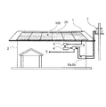
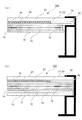
図1は、本実施の形態が適用される融雪太陽電池パネル付き屋根の一例を説明する図である。図1に示すように、融雪太陽電池パネル付き屋根1は、建物2の上部に施工され、複数の融雪太陽電池パネル100から構成された太陽電池アレイが設置されている。
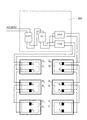
融雪太陽電池パネル100を構成する太陽電池モジュール20を備えた発電システムは、太陽電池モジュール20が発電した直流電圧を一つにまとめる接続箱3と、分電設備として、太陽電池モジュール20が発電した直流電圧を交流電圧に変換するパワーコンディショナ(直流交流変換器)4と、パワーコンディショナ4により変換された交流電圧を建物2内の家電製品E等に供給する分電盤5とを有している。パワーコンディショナ4を介して分電盤5に供給された電力は、建物2外の給電設備7にも供給される。ここで、給電設備7は、発電所にて発電した電力を供給する設備である。また、給電設備7から供給された電力は、分電盤5を含む分電設備に供給され、さらに、建物2内の家電製品E等に供給される。建物2外の給電設備7に供給される電力と、給電設備7から供給された電力は、それぞれ、売電メータ6aと買電メータ6bにより表示される。
<Roof with snow melting solar panel>
FIG. 1 is a diagram for explaining an example of a roof with a snow melting solar panel to which the present embodiment is applied. As shown in FIG. 1, a
In the power generation system including the
接続箱3は、太陽電池モジュール20と分電設備(パワーコンディショナ4,分電盤5)との間を接続するコネクタ等の接続部を収納し、太陽電池モジュール20からの電流は接続箱3を経由してパワーコンディショナ4へ流れている。また、パワーコンディショナ4には、太陽電池モジュール20から建物2外の給電設備7へ供給する電力を変調するいわゆるインバーター機能等を搭載することも可能である。
The
融雪太陽電池パネル100は、所定の屋根板に取り付けられる。屋根板としては、例えば金属板が挙げられる。具体的には、鉄、アルミニウム、銅、亜鉛、チタンあるいはそれらの基合金等が採用される。熱伝導性に優れる点では、銅、アルミニウムまたはそれらの基合金が好ましい。また、耐久性、価格等の面では、鋼板が適切である。
The snow melting
<融雪太陽電池パネル>
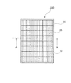
図2は、本実施の形態が適用される融雪太陽電池パネルの一例を説明する概略平面図である。図2に示す融雪太陽電池パネル100は、全体として長方形板状の形状を有し、表面側(受光面)には、複数の太陽電池セルから構成された太陽電池モジュール20と、太陽電池モジュール20の裏側(屋根側)に配設された導電性ゴムシート10を有している。太陽電池モジュール20と導電性ゴムシート10の外周縁部は、金属製フレーム30により固定されている。
融雪太陽電池パネル100の大きさは、例えば、縦130cm〜200cm程度、幅65cm〜100cm程度、厚さ4cm〜10cm程度の範囲である。尚、図示しないが、太陽電池モジュール20の表面側には強化ガラス板23(図3参照)が設けられている。
<Snow Melting Solar Panel>
FIG. 2 is a schematic plan view for explaining an example of a snowmelt solar cell panel to which the present embodiment is applied. The snow-melting
The size of the snow-melting
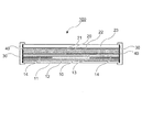
図3は、図2に示す融雪太陽電池パネル100のA−A断面図である。
図3に示すように、融雪太陽電池パネル100は、前述した建物2の屋根に取り付けられる側(図面の下側)から順に、断熱材からなる断熱シート11と、例えばアルミニウム等の金属膜からなる遠赤外線反射膜12と、ゴム成分に遠赤外線放射性物質を配合してなる導電性ゴムシート10と、例えばフッ素樹脂やポリエステル樹脂等からなるバックシート13と、例えばエチレン−酢酸ビニル共重合体(EVA)等からなる透明樹脂層21を介してバックシート13に接着された太陽電池モジュール20と、太陽電池モジュール20の表面側に透明樹脂層22を介して太陽電池モジュール20に接着された強化ガラス板23と、が積層されている。さらに、導電性ゴムシート10には、所定の配線により外部電源(図示せず)に結合した一対の電極14が配設されている。
FIG. 3 is a cross-sectional view of the snow melting
As shown in FIG. 3, the snow melting
これら断熱シート11、遠赤外線反射膜12、導電性ゴムシート10、バックシート13、太陽電池モジュール20および強化ガラス板23を含む融雪太陽電池パネル100の端部は、これら構成要素の外周縁部に封止材40を介して囲むように形成された、例えばアルミニウム等からなる金属製フレーム30により一体になるように固定されている。
また、導電性ゴムシート10と太陽電池モジュール20とを、所定の真空ラミネーターを用いることにより透明樹脂層21を介して積層し、一体化することができる。
The end portions of the snow-melting
Moreover, the
(導電性ゴムシート10)
導電性ゴムシート10は、ゴム成分と、ゴム成分に配合された遠赤外線放射性物質とを含み、さらに、ゴム成分に導電性を付与する導電性フィラーが、必要に応じて配合されている。
ゴム成分としては、例えば、天然ゴム(NR)、スチレン−ブタジエンゴム(SBR)、ブタジエンゴム(BR)、イソプレンゴム(IR)、エチレン−αオレフィン系共重合ゴム、ブチルゴム(IIR)、シリコーンゴム、アクリロニトリル−ブタジエンゴム(NBR)、エピクロルヒドリンゴム(ECO)、クロロプレンゴム(CR)、ウレタンゴム等が挙げられる。これらのゴム成分は、1種単独または2種以上併用してもよい。
(Conductive rubber sheet 10)
The
Examples of the rubber component include natural rubber (NR), styrene-butadiene rubber (SBR), butadiene rubber (BR), isoprene rubber (IR), ethylene-α olefin copolymer rubber, butyl rubber (IIR), silicone rubber, Examples include acrylonitrile-butadiene rubber (NBR), epichlorohydrin rubber (ECO), chloroprene rubber (CR), and urethane rubber. These rubber components may be used alone or in combination of two or more.
本実施の形態では、導電性ゴムシート10を構成するゴム成分としてエチレン−α−オレフィン系共重合ゴムを使用している。エチレン−α−オレフィン系共重合体ゴムは、エチレンとα−オレフィン又はこれらと非共役ジエンとの共重合体であって実質的に飽和型の共重合体ゴムである。α−オレフィンとしては、炭素数3〜6のα−モノオレフィンが好ましく、例えば、プロピレン、1−ブテン、1−ペンテン、1−ヘキセン等を挙げることができる。非共役ジエンとしては、例えば、ジシクロペンタジエン、1,4−ヘキサジエン、シクロオクタジエン、メチレンノルボルネン、5−エチリデン−2−ノルボルネン等が挙げられる。これらのうち、ジシクロペンタジエン、5−エチリデン−2−ノルボルネンが好ましい。
In the present embodiment, ethylene-α-olefin copolymer rubber is used as a rubber component constituting the
エチレン−α−オレフィン系共重合体ゴムの具体例としては、例えば、エチレン−プロピレン二元共重合体ゴム、エチレン−プロピレン−ブテン三元共重合体ゴム、エチレン−1−ブテン二元共重合体ゴム、エチレン−プロピレン−非共役ジエン三元共重合体ゴム、エチレン−プロピレン−1−ブテン−非共役ジエン共重合体ゴム、エチレン−1−ブテン−非共役ジエン多元重合体ゴム等が挙げられる。これらの中でも、エチレン−プロピレン−非共役ジエン三元共重合体ゴム(EPDM)が好ましい。 Specific examples of the ethylene-α-olefin copolymer rubber include, for example, ethylene-propylene binary copolymer rubber, ethylene-propylene-butene terpolymer rubber, and ethylene-1-butene binary copolymer. Examples thereof include rubber, ethylene-propylene-nonconjugated diene terpolymer rubber, ethylene-propylene-1-butene-nonconjugated diene copolymer rubber, and ethylene-1-butene-nonconjugated diene multipolymer rubber. Among these, ethylene-propylene-nonconjugated diene terpolymer rubber (EPDM) is preferable.
エチレンと共重合可能な他の共重合性モノマーとしては、例えば、メチルアクリレート、エチルアクリレート、メチルメタクリレート、エチルメタクリレート等のアクリル酸エステルまたはメタクリル酸エステル;スチレン、α−メチルスチレン等の芳香族ビニル化合物;アクリロニトリル等のニトリル基含有ビニル化合物;塩化ビニル等のハロゲン含有ビニル化合物等が挙げられる。共役ジエンとしては、例えば、1,3−ブタジエン、2,3−ジメチルブタジエン、イソプレン、1,3−ペンタジエン等が挙げられる。 Examples of other copolymerizable monomers copolymerizable with ethylene include acrylic acid esters or methacrylic acid esters such as methyl acrylate, ethyl acrylate, methyl methacrylate, and ethyl methacrylate; aromatic vinyl compounds such as styrene and α-methyl styrene. A nitrile group-containing vinyl compound such as acrylonitrile; a halogen-containing vinyl compound such as vinyl chloride; Examples of the conjugated diene include 1,3-butadiene, 2,3-dimethylbutadiene, isoprene, 1,3-pentadiene, and the like.
エチレン−α−オレフィン系共重合ゴムのムーニー粘度は、通常、10以上、好ましくは40以上である。但し、通常、180以下、好ましくは140以下である。また、ヨウ素価は、通常、80以下、好ましくは20以下である。エチレン−α−オレフィン系共重合ゴム中のエチレン単位は、通常、10モル%以上、好ましくは50モル%以上である。但し、通常、90モル%以下、好ましくは、70モル%以下である。 The Mooney viscosity of the ethylene-α-olefin copolymer rubber is usually 10 or more, preferably 40 or more. However, it is usually 180 or less, preferably 140 or less. The iodine value is usually 80 or less, preferably 20 or less. The ethylene unit in the ethylene-α-olefin copolymer rubber is usually 10 mol% or more, preferably 50 mol% or more. However, it is usually 90 mol% or less, preferably 70 mol% or less.
遠赤外線放射性物質とは、波長が4μm以上の遠赤外域の放射率が理想黒体に近く、且つ近赤外域の放射率が著しく低い放射スペクトルを有する物質である。本実施の形態では、導電性ゴムシート10に配合される遠赤外線放射性物質から放射される遠赤外線は、導電性ゴムシート10に積層された太陽電池モジュール20を透過し、冬季には強化ガラス板23上に積雪した雪の水分子に直接作用する波長を有することが好ましい。
遠赤外線放射性物質の具体例としては、例えば、遷移金属元素酸化物系のセラミック、天然鉱石および天然炭化物等が知られている。これらを1種単独または2種以上併用してもよい。
The far-infrared radioactive substance is a substance having a radiation spectrum in which the emissivity in the far-infrared region having a wavelength of 4 μm or more is close to an ideal black body and the emissivity in the near-infrared region is extremely low. In the present embodiment, the far infrared rays emitted from the far-infrared radioactive material blended in the
Specific examples of the far-infrared radioactive material include, for example, transition metal element oxide ceramics, natural ores, and natural carbides. These may be used alone or in combination of two or more.
遷移金属元素酸化物系のセラミックスとしては、例えば、TiO2、SiO2、ZrO2、Al2O3、MgO、BaSO4、MnO2、Fe2O3、ZrSiO2、CoO、CuO、CrO3、TiO、TiN、ZrC、TiC、SnO2等の金属酸化物の微粒子;2MgO・2Al2O3・5SiO2(コージライト)等のこれらの複合金属酸化物の微粒子;ネオジウム、ランタン、イットリウム等の希土類金属の酸化物が挙げられる。さらに、少量のシリカ、アルカリ金属酸化物、アルカリ土類金属酸化物、第8族金属酸化物、燐化合物等が含まれていてもよい。天然鉱石としては、例えば、雲母、トルマリン(電気石)、オーラストン等が挙げられる。天然炭化物としては、例えば、海藻を炭化し微粉末にしたもの、備長炭に代表される炭類、カーボンブラック、ケッチェンブラック、カーボンファイバー、カーボンナノファイバー等が挙げられる。
尚、これらの物質の中には、ゴム成分に導電性を付与する導電性フィラーとして作用するものもある。例えば、カーボンブラックの中でも、アセチレンの熱分解によって製造されるアセチレンブラック、さらに、オイルファーネスブラックの一種であるケッチェンブラック等が好ましい。
Examples of the transition metal element oxide-based ceramics include TiO 2 , SiO 2 , ZrO 2 , Al 2 O 3 , MgO, BaSO 4 , MnO 2 , Fe 2 O 3 , ZrSiO 2 , CoO, CuO, CrO 3 , Fine particles of metal oxides such as TiO, TiN, ZrC, TiC, SnO 2 ; Fine particles of composite metal oxides such as 2MgO · 2Al 2 O 3 · 5SiO 2 (cordierite); Rare earth such as neodymium, lanthanum, yttrium Examples thereof include metal oxides. Further, a small amount of silica, alkali metal oxide, alkaline earth metal oxide, Group 8 metal oxide, phosphorus compound, or the like may be contained. Examples of natural ores include mica, tourmaline (tourmaline), and aurastone. Examples of the natural carbide include carbonized seaweed into fine powder, charcoal represented by Bincho charcoal, carbon black, ketjen black, carbon fiber, carbon nanofiber, and the like.
Some of these substances act as conductive fillers that impart conductivity to the rubber component. For example, among carbon blacks, acetylene black produced by thermal decomposition of acetylene, ketjen black which is a kind of oil furnace black, and the like are preferable.
遠赤外線放射性物質の使用量は、通常、ゴム成分100重量部に対し、遠赤外線放射性物質1重量部以上、好ましくは5重量部以上の範囲である。但し、通常、ゴム成分100重量部に対し、遠赤外線放射性物質150重量部以下、好ましくは100重量部以下、さらに好ましくは80重量部以下の範囲である。 The amount of the far-infrared radioactive substance used is usually in the range of 1 part by weight or more, preferably 5 parts by weight or more with respect to 100 parts by weight of the rubber component. However, it is usually in the range of 150 parts by weight or less, preferably 100 parts by weight or less, and more preferably 80 parts by weight or less with respect to 100 parts by weight of the rubber component.
導電性フィラーとしては、例えば、黒鉛、球晶黒鉛、黒鉛ウイスカー、カーボンブラック、炭素短繊維、銀、銅、ニッケル、ステンレス、鉄、錫、アルミ、亜鉛、青銅、黄銅、炭化ニオブ、炭化ジルコニウム、炭化チタン、炭化タングステン、炭化硅素、硼化ジルコニウム、硼化チタン、窒化チタン、窒化ニオブ等が挙げられる。 Examples of the conductive filler include graphite, spherulite graphite, graphite whisker, carbon black, carbon short fiber, silver, copper, nickel, stainless steel, iron, tin, aluminum, zinc, bronze, brass, niobium carbide, zirconium carbide, Examples thereof include titanium carbide, tungsten carbide, silicon carbide, zirconium boride, titanium boride, titanium nitride, and niobium nitride.
導電性フィラーの使用量は、通常、ゴム成分100重量部に対し、導電性フィラー10重量部以上、好ましくは30重量部以上、さらに好ましくは50重量部以上である。但し、通常、導電性フィラー150重量部以下、好ましくは100重量部以下、さらに好ましくは80重量部以下である。導電性フィラーを過度に使用すると、導電性ゴムシート10の発熱量が飽和する傾向がある。
The amount of the conductive filler used is usually 10 parts by weight or more, preferably 30 parts by weight or more, and more preferably 50 parts by weight or more with respect to 100 parts by weight of the rubber component. However, the conductive filler is usually 150 parts by weight or less, preferably 100 parts by weight or less, and more preferably 80 parts by weight or less. If the conductive filler is excessively used, the calorific value of the
(導電性ゴムシート10の製造方法)
本実施の形態における導電性ゴムシート10は、上述したゴム成分に遠赤外線放射性物質、必要に応じて添加される導電性フィラー、ゴム用配合剤を配合したゴム組成物を調製し、これを加硫することにより成形される。また、導電性ゴムシート10を成形する際には、必要に応じて他の補強剤を混合することができる。このような補強剤としては、例えば、酸化スズ、酸化亜鉛、酸化アルミニウム、酸化モリブデン、酸化マグネシウム、酸化カルシウム、酸化亜鉛、酸化鉛等の絶縁性金属酸化物;水酸化マグネシウム、水酸化アルミニウム、水酸化カルシウム、水酸化亜鉛、水酸化鉛等の金属水酸化物;炭酸マグネシウム、炭酸アルミニウム、炭酸カルシウム、炭酸バリウム等の炭酸塩;珪酸マグネシウム、珪酸カルシウム、珪酸ナトリウム、珪酸アルミニウム等の珪酸塩;硫酸アルミニウム、硫酸カルシウム、硫酸バリウム等の硫酸塩;鉄粉等の金属粉;炭素繊維等の導電性繊維等;珪藻土、アスベスト、リトポン(硫化亜鉛/硫酸バリウム)、グラファイト、フッ化カーボン、フッ化カルシウム、ワラスナイト、ガラス粉末等が挙げられる。
(Method for producing conductive rubber sheet 10)
The
(ゴム用配合剤)
本実施の形態において、導電性ゴムシート10を成形する際には、通常、ゴム用配合剤として知られる配合剤が使用される。このような配合剤としては、例えば、架橋剤、架橋促進剤、オイル、老化防止剤、安定剤、着色剤等の種々の薬剤を必要に応じて適宜配合して使用することができる。
架橋剤としては、例えば、有機過酸化物系架橋剤、硫黄系加硫剤、ビスマレイミド化合物等が挙げられる。本実施の形態では、エチレン−α−オレフィン系共重合ゴムを有機過酸化物系架橋剤により架橋し、導電性ゴムシート10を成形することが好ましい。
(Rubber compounding agent)
In the present embodiment, when the
Examples of the crosslinking agent include organic peroxide crosslinking agents, sulfur vulcanizing agents, bismaleimide compounds, and the like. In the present embodiment, it is preferable to form the
有機過酸化物系架橋剤としては、例えば、ジアルキルパーオキサイド類、ジアシルパーオキサイド類、パーオキシエステル類等が挙げられる。ジアルキルパーオキサイドとしては、ジクミルパーオキサイド、ジ−t−ブチルパーオキサイド、2,5−ジメチル−2,5−ジ(t−ブチルパーオキシ)−3−ヘキシン、2,5−ジメチル−2,5−ジ(t−ブチルパーオキシ)ヘキサン、1,3−ビス(t−ブチルパーオキシイソプロピル)ベンゼン等が挙げられる。ジアシルパーオキサイドとして、ベンゾイルパーオキサイド、イソブチリルパーオキサイド等が挙げられる。パーオキシエステルとして、2,5−ジメチル−2,5−ビス(ベンゾイルパーオキシ)ヘキサン、t−ブチルパーオキシイソプロピルカーボネート等)等が挙げられる。 Examples of the organic peroxide crosslinking agent include dialkyl peroxides, diacyl peroxides, peroxyesters, and the like. Dialkyl peroxides include dicumyl peroxide, di-t-butyl peroxide, 2,5-dimethyl-2,5-di (t-butylperoxy) -3-hexyne, 2,5-dimethyl-2, Examples include 5-di (t-butylperoxy) hexane and 1,3-bis (t-butylperoxyisopropyl) benzene. Examples of the diacyl peroxide include benzoyl peroxide and isobutyryl peroxide. Examples of peroxyesters include 2,5-dimethyl-2,5-bis (benzoylperoxy) hexane, t-butylperoxyisopropyl carbonate, and the like.
有機過酸化物系架橋剤を用いる場合は、通常、架橋助剤を併用する。架橋助剤としては、トリアリルシアヌレート、トリメチロールプロパントリメタクリレート、N,N’−m−フェニレンビスマレイミド等が挙げられる。架橋助剤の使用量は特に限定されず、架橋剤の種類等に応じて適宜決められる。 When using an organic peroxide crosslinking agent, a crosslinking aid is usually used in combination. Examples of the crosslinking aid include triallyl cyanurate, trimethylolpropane trimethacrylate, N, N′-m-phenylenebismaleimide and the like. The amount of the crosslinking aid used is not particularly limited and can be appropriately determined according to the type of the crosslinking agent.
硫黄系加硫剤としては、例えば、粉末硫黄、沈降硫黄等の硫黄;4,4’−ジチオモルホリン、テトラメチルチウラムジスルフィド、テトラエチルチウラムジスルフィド、高分子多硫化物等有機硫黄化合物等が挙げられる。 Examples of the sulfur-based vulcanizing agent include sulfur such as powdered sulfur and precipitated sulfur; organic sulfur compounds such as 4,4'-dithiomorpholine, tetramethylthiuram disulfide, tetraethylthiuram disulfide, and polymer polysulfide.
硫黄系加硫剤を用いる場合は、通常、加硫促進剤及び加硫促進助剤を併用する。加硫促進剤としては、例えば、チウラム系、スルフェンアミド系、チアゾール系、ジチオカルバミン酸塩系、チオウレア系等の含硫黄促進剤;アルデヒド・アンモニア系、アルデヒド・アミン系、グアニジン系等の含窒素促進剤等が挙げられる。 When a sulfur vulcanizing agent is used, a vulcanization accelerator and a vulcanization acceleration aid are usually used in combination. Examples of the vulcanization accelerator include sulfur-containing accelerators such as thiuram, sulfenamide, thiazole, dithiocarbamate, and thiourea; nitrogen-containing aldehyde / ammonia, aldehyde / amine, and guanidine Examples include accelerators.
加硫促進剤の中でも、チウラム系促進剤が好ましい。チウラム系促進剤の具体例としては、例えば、テトラメチルチウラムジスルフィド(TT)(TMTD)、テトラメチルチウラムモノスルフィド(TS)(TMTM)、テトラエチルチウラムジスルフィド(TET)(TETD)、テトラブチルチウラムジスルフィド(TBT)(TBTD)、ジペンタメチレンチウラムヘキサスルフィド(TRA)(DPTT)、テトラベンジルチウラムジスルフィド等が挙げられる。また、加硫促進助剤としては、亜鉛華、酸化マグネシウム等が挙げられる。加硫促進剤及び加硫促進助剤の使用量は特に限定されず、硫黄加硫剤の種類等に応じて適宜決められる。 Of the vulcanization accelerators, thiuram accelerators are preferred. Specific examples of the thiuram accelerator include, for example, tetramethylthiuram disulfide (TT) (TMTD), tetramethylthiuram monosulfide (TS) (TMTM), tetraethylthiuram disulfide (TET) (TETD), tetrabutylthiuram disulfide ( TBT) (TBTD), dipentamethylene thiuram hexasulfide (TRA) (DPTT), tetrabenzyl thiuram disulfide and the like. Examples of the vulcanization acceleration aid include zinc white and magnesium oxide. The usage-amount of a vulcanization accelerator and a vulcanization acceleration adjuvant is not specifically limited, It determines suitably according to the kind etc. of sulfur vulcanization agent.
ビスマレイミド化合物としては、N,N’−(m−フェニレン)ビスマレイミド、N,N’−(p−フェニレン)ビスマレイミド、N,N’−(o−フェニレン)ビスマレイミド、N,N’−(1,3−ナフチレン)ビスマレイミド、N,N’−(1,4−ナフチレン)ビスマレイミド、N,N’−(1,5−ナフチレン)ビスマレイミド、N,N’−(3,3’−ジメチル−4,4’−ビフェニレン)ビスマレイミド、N,N’−(3,3’−ジクロロ−4,4’−ビフェニレン)ビスマレイミド等が挙げられる。 Examples of the bismaleimide compound include N, N ′-(m-phenylene) bismaleimide, N, N ′-(p-phenylene) bismaleimide, N, N ′-(o-phenylene) bismaleimide, N, N′-. (1,3-naphthylene) bismaleimide, N, N ′-(1,4-naphthylene) bismaleimide, N, N ′-(1,5-naphthylene) bismaleimide, N, N ′-(3,3 ′ -Dimethyl-4,4'-biphenylene) bismaleimide, N, N '-(3,3'-dichloro-4,4'-biphenylene) bismaleimide and the like.
ビスマレイミド化合物を用いる場合は、必要に応じて、例えば、p−キノンジオキシム、p,p’−ジベンゾイルキノンジオキシム、テトラクロロ−p−ベンゾキノン等のオキシム類;4,4’−ジチオジモルホリン、N−エチルモルホリン、モルホリン等のモルホリン化合物等を併用することができる。 When a bismaleimide compound is used, for example, oximes such as p-quinonedioxime, p, p'-dibenzoylquinonedioxime, tetrachloro-p-benzoquinone; Morpholine compounds such as morpholine, N-ethylmorpholine, morpholine and the like can be used in combination.
架橋剤の配合量は、特に限定されないが、通常、ゴム成分100重量部に対して、0.1重量部〜10重量部、好ましくは、0.3重量部〜7重量部、より好ましくは、0.5重量部〜5重量部である。 The amount of the crosslinking agent is not particularly limited, but is usually 0.1 to 10 parts by weight, preferably 0.3 to 7 parts by weight, more preferably 100 parts by weight of the rubber component. 0.5 parts by weight to 5 parts by weight.
オイルとしては、例えば、芳香族系オイル、ナフテン系オイル、パラフィン系オイル等のプロセスオイル等の伸展油;ジオクチルフタレート等の可塑剤;パラフィンワックス、カルナバワックス等のワックス等が挙げられる。 Examples of the oil include extension oils such as aromatic oils, naphthenic oils, and paraffinic oils; plasticizers such as dioctyl phthalate; waxes such as paraffin wax and carnauba wax.
また、本実施の形態において、導電性ゴムシート10には、老化防止剤を配合することが好ましい。老化防止剤としては、例えば、ポリ−(2,2,4−トリメチル−1,2−ジヒドロキノン)等のアミン−ケトン系;N−フェニル−N’−イソプロピル−p−フェニレンジアミン、N−フェニル−N’−(3−メタクリロイルオキシ−2−ヒドロキシプロピル)−p−フェニレンジアミン等のアミン系;2,2’−メチレンビス(4−エチル−6−t−ブチルフェノール)等のフェノール系;2−メルカプトベンズイミダゾール等が挙げられる。老化防止剤の配合量は、特に限定されないが、通常、ゴム成分100重量部に対して、0.1重量部〜10重量部、好ましくは、0.3重量部〜7重量部、より好ましくは、0.5重量部〜5重量部である。
Moreover, in this Embodiment, it is preferable to mix | blend anti-aging agent with the
本実施の形態では、導電性ゴムシート10の製造方法は特に限定されないが、通常、先ず、ロール、バンバリーミキサー等の混合機により、エチレン−α−オレフィン系共重合体ゴム等のゴム成分と遠赤外線放射性物質または導電性フィラー、必要に応じて他のゴム成分、各種補強材、架橋剤等の他の配合剤を添加し、加硫剤が分解しない温度で混練・混合することによって未加硫ゴム組成物を調製する。次に、調製した未加硫ゴム組成物を、ロール成形、押出成形等の従来公知の成形方法によって所定のシート形状(未加硫ゴムシート)に成形する。
In the present embodiment, the method for producing the
その後、シート形状に成形された未加硫ゴムシートをスチーム加硫等の方法により硬化させる。硬化反応の温度は、特に限定されないが、通常、100℃〜200℃、好ましくは、130℃〜190℃、より好ましくは、140℃〜180℃である。また、硬化反応の時間は、硬化方法、温度、形状などにより適宜変更され、特に限定されないが、通常、1分間以上、5時間以下である。尚、必要に応じて、二次硬化を行ってもよい。硬化方法としては、プレス加熱、蒸気加熱、オーブン加熱、熱風加熱等、通常、ゴムの硬化処理に用いられる方法から適宜選択することができる。 Thereafter, the unvulcanized rubber sheet formed into a sheet shape is cured by a method such as steam vulcanization. The temperature of the curing reaction is not particularly limited, but is usually 100 ° C to 200 ° C, preferably 130 ° C to 190 ° C, and more preferably 140 ° C to 180 ° C. The time for the curing reaction is appropriately changed depending on the curing method, temperature, shape and the like, and is not particularly limited, but is usually 1 minute or more and 5 hours or less. In addition, you may perform secondary hardening as needed. The curing method can be appropriately selected from methods usually used for rubber curing, such as press heating, steam heating, oven heating, and hot air heating.
本実施の形態では、導電性ゴムシート10に一対の電極14(図3参照)が取り付けられている。一対の電極14を取り付ける方法は特に限定されない。例えば、一対の電極14を2枚の未加硫ゴムシートで挟み、その状態で未加硫ゴムシートを硬化させることにより、一対の電極14を埋め込んだ導電性ゴムシート10を成形する方法、予め未加硫ゴムシートを硬化させ、その後、一対の電極14を接着剤等により貼り付ける方法等が挙げられる。また、一対の電極14は、導電性ゴムシート10の両端にそれぞれ設けても良いし、一対の電極14により導電性ゴムシート10を挟んでも良い。
尚、本実施の形態では、導電性ゴムシート10の硬化処理は、後述するように、強化ガラス板23、太陽電池モジュール20、バックシート13等と未加硫ゴムシートとを積層し、これらを、所定のラミネーターを用いて加熱し一体化する操作と同時に行うことができる。
In the present embodiment, a pair of electrodes 14 (see FIG. 3) is attached to the
In this embodiment, the
このように成形された導電性ゴムシート10の硬度は特に限定されないが、本実施の形態では、JIS−A硬度(JIS6301に準拠)として、少なくとも55である。但し、通常、85以下であることが好ましい。導電性ゴムシート10の硬度が過度に低いと、機械的強度が低下する傾向がある。また、導電性ゴムシート10の硬度が過度に高いと、太陽電池モジュール20の全体を覆うことが困難になる傾向がある。
また、導電性ゴムシート10の厚さは、通常、0.2mm以上、好ましくは、1mm以上である。但し、通常、厚さは、15mm以下、好ましくは、10mm以下である。導電性ゴムシート10が過度に薄いと、発熱量が減少し、融雪機能が低下する傾向がある。また、導電性ゴムシート10が過度に厚いと、導電性ゴムシート10の全体の重量が大きくなり、さらに、消費電力が大きくなる傾向がある。
The hardness of the
Further, the thickness of the
(太陽電池モジュール20)
本実施の形態で使用する太陽電池モジュール20の構造は特に限定されず、例えば、アモルファスシリコン(a−Si)型太陽電池が挙げられる。一般に、アモルファスシリコン(a−Si)型太陽電池は、標準青板ガラス基板上にSiO2とSnO2の2層からなる透明電極、p/i/n(又はn/i/p)型のアモルファスシリコンからなる発電膜及びAlからなる裏面電極を順次積層した構成となっている。このようなa−Si型太陽電池を複数個備えた太陽電池パネルの構造体としては、強化ガラス板23の裏面側から裏面電極の一部が銅箔電極との接触部で銀ペーストにより接着され、互いに電気的に接続されている。
(Solar cell module 20)
The structure of the
尚、バックシート13としては、前述したフッ素樹脂やポリエステル樹脂等以外に、例えば、ポリエチレン、ポリスチレン、塩化ビニル、フェノール、ポリウレタン等からなる硬質の発泡剤からなる樹脂フォーム、ポリカーボネート樹脂、SUS等の金属板、ガラス板等が使用できる。
As the
また、アモルファスシリコン(a−Si)型太陽電池に採用される太陽電池セルのアモルファスシリコン層の積層数としては、前述した2層構造以外、1層、3層、4層以上も可能である。また、太陽電池セルとしてシリコン結晶層を採用することも可能である。シリコン結晶層としては、シリコン単結晶、シリコン多結晶のいずれをも適用可能である。 さらに、太陽電池セルには化合物半導体層を備えることも可能である。化合物半導体の組成としては、例えば、2元系ではGaAsやCdS等、3元系ではCuInSe2等が挙げられる。 Further, the number of laminated amorphous silicon layers of the solar battery cell employed in the amorphous silicon (a-Si) type solar battery may be one layer, three layers, four layers or more other than the two-layer structure described above. It is also possible to employ a silicon crystal layer as the solar battery cell. As the silicon crystal layer, either silicon single crystal or silicon polycrystal can be applied. Furthermore, the solar battery cell can be provided with a compound semiconductor layer. Examples of the composition of the compound semiconductor include GaAs and CdS in the binary system, and CuInSe 2 in the ternary system.
(遠赤外線反射膜12)
本実施の形態が適用される融雪太陽電池パネル100では、導電性ゴムシート10の裏側(屋根側)に遠赤外線反射膜12を配置している。遠赤外線反射膜12を配置することにより、導電性ゴムシート10に配合した遠赤外線放射性物質から放射された遠赤外線が太陽電池モジュール20の受光面側に反射される。これにより、冬季の太陽電池モジュール20の受光面側の融雪が促進される。遠赤外線反射膜12の材料は、遠赤外線を反射することができるものであれば特に限定されず、本実施の形態では、前述したように例えばアルミニウム等の金属膜を使用している。
(Far-infrared reflective film 12)
In the snowmelt
本実施の形態では、導電性ゴムシート10に埋め込まれた一対の電極14に外部電源(図示せず)から所定の電圧を印加してゴム成分に通電することにより、導電性ゴムシート10は高温に発熱することなく、配合された遠赤外線放射性物質から遠赤外線が放射される。これにより、例えば、冬季には、放射された遠赤外線が太陽電池モジュール20の受光面側の積雪を融雪することができる。このような融雪太陽電池パネル100は、融雪完了時には太陽光発電も可能になり、積雪地帯であっても太陽光発電の効率が高まる。
In the present embodiment, the
本実施の形態が適用される融雪太陽電池パネル付き屋根1は、積雪の無い通常の使用では、太陽電池モジュール20が太陽光発電した電力が、分電設備である分電盤5にて建物2内の家電製品E等あるいは給電設備7へ供給される。一方、積雪時では、所定の切換スイッチ(図示せず)を操作してパワーコンディショナ4の機能を切り換え、給電設備7から融雪太陽電池パネル100へ給電する。これにより、導電性ゴムシート10に通電され、導電性ゴムシート10に配合された遠赤外線放射性物質から放射された遠赤外線により、太陽電池モジュール20の受光面の積雪を融雪することができる。尚、導電性ゴムシート10への通電は、パワーコンディショナ4の機能を切り換えを行うことなく、独立して外部電源から行うことも可能である。
また、図示しないが、パワーコンディショナ4の機能を切り換える場合は、例えば、所定の降雪センサを取り付け、水と温度により降雪を検知することにより作動させる。
In the
Although not shown, when the function of the
(融雪太陽電池パネルの取り付け方法)
本実施の形態では、融雪太陽電池パネル100は、所定の取り付け金具を用いて、通常、一定の傾斜(例えば、15°〜20°程度)をつけた屋根板に取り付けられる。ところで、傾斜を付けた融雪太陽電池パネル100の設置条件では、導電性ゴムシート10に配合した遠赤外線放射性物質から放射された遠赤外線により太陽電池モジュール20の受光面上で溶けた雪が傾斜により下方に流れ、金属製フレーム30の近辺で凍結する場合がある。このような傾向は外気温が低い場合に顕著となり、凍結部分では、氷の上にさらに積雪するため、太陽電池モジュール20の下部に土手が形成される場合がある。
このような場合、一定の傾斜をつけた屋根板に取り付けられた太陽電池モジュール20の下部に向かうほど導電性ゴムシート10に配合する遠赤外線放射性物質の量を増大させることにより、金属製フレーム30の近辺における氷の凍結を防止することができる。
(How to install a snow melting solar panel)
In the present embodiment, the snowmelt
In such a case, the
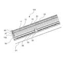
図4は、本実施の形態が適用される融雪太陽電池パネル101の屋根への取り付け状態の一例を説明する図である。図3と同様な構成については同じ符号を用い説明を省略する。図4に示すように、融雪太陽電池パネル101は、縦桟54に固定したスレート・板金金具55により、一定の傾斜をつけたスレート53に固定される。尚、スレート・板金金具55は、スレート53の下側に組み込まれた野路板52及び垂木51に達する所定の木ねじ(図示せず)により固定されている。
本実施の形態では、融雪太陽電池パネル101を構成する導電性ゴムシート10の端部10aは、封止材40を介して金属製フレーム30と接着される部分が、断熱シート11及び遠赤外線反射膜12の端部を回り込むように形成されている。
これにより、太陽電池モジュール20下部の金属製フレーム30の部分にも、遠赤外線が放射され、この部分での氷の凍結が防止される。
FIG. 4 is a diagram for explaining an example of a state in which the snow-melting
In the present embodiment, the
Thereby, far-infrared rays are also radiated to the portion of the
図5(a)及び図5(b)は、本実施の形態が適用される融雪太陽電池パネル102,103の金属製フレーム30への取り付け方法を説明する概略断面図である。尚、図3に示した融雪太陽電池パネル100と同様な構成については同じ符号を使用し、それらについての詳細な説明は省略する。
図5(a)に示す融雪太陽電池パネル102は、図面の下側から順に、防湿シート(バックシート)15と、導電性ゴムシート10と、防湿シート16と、透明樹脂層21を介して防湿シート16に接着された太陽電池モジュール20と、太陽電池モジュール20の表面側に透明樹脂層22を介して太陽電池モジュール20に接着された強化ガラス板23と、が積層されている。導電性ゴムシート10には、所定の配線により外部電源(図示せず)に結合した一対の電極14が配設されている。
FIG. 5A and FIG. 5B are schematic cross-sectional views for explaining a method of attaching the snow melting
A snow-melting
図5(a)に示す融雪太陽電池パネル102では、防湿シート16、太陽電池モジュール20および強化ガラス板23を含む積層体の端部の外側から、アルミニウム等からなる金属製フレーム30が嵌め込まれている。これにより、融雪太陽電池パネル102は、金属製フレーム30に固定されている。尚、防湿シート16、太陽電池モジュール20および強化ガラス板23を含む積層体の端部は、封止材40によりシールされている。
In the snowmelt
ここで、防湿シート15,16は、通常、耐候性、防湿性、絶縁性等の性質を有し、例えば、ポリビニルフルオライド(PVF)シートとポリエチレンテレフタレート(PET)シートとの積層シート、高密度ポリエチレンシートとPETシートとの積層シート、低密度ポリエチレンシートとポリフッ化ビニリデンとポリメチルメタクリレートを含有するシートとの積層シート等が挙げられる。
本実施の形態では、導電性ゴムシート10の表面側(図面の上側)と裏側(図面の下側、屋根側)に、それぞれ防湿シート15を設けることにより、導電性ゴムシート10を防湿することに加え、長期間の発熱効果を得ることができる。
Here, the moisture-
In the present embodiment, the
次に、図5(b)に示す融雪太陽電池パネル103は、図面の下側から順に、防湿シート15,17と、遠赤外線反射膜12と、導電性ゴムシート10と、防湿シート16と、透明樹脂層21を介して防湿シート16に接着された太陽電池モジュール20と、太陽電池モジュール20の表面側に透明樹脂層22を介して太陽電池モジュール20に接着された強化ガラス板23と、が積層されている。導電性ゴムシート10には、所定の配線により外部電源(図示せず)に結合した一対の電極14が配設されている。
Next, the snow-melting
図5(b)に示す融雪太陽電池パネル103では、最下層の防湿シート15から最上層の強化ガラス板23を含む全ての層を含む積層体の端部の外側から、アルミニウム等からなる金属製フレーム30が嵌め込まれている。これにより、融雪太陽電池パネル103は、金属製フレーム30に固定されている。尚、防湿シート16、太陽電池モジュール20および強化ガラス板23を含む積層体の端部は、封止材40によりシールされている。
本実施の形態では、全ての層を含む積層体の端部の外側から金属製フレーム30を嵌め込み、融雪太陽電池パネル103を金属製フレーム30に固定することにより、発熱した導電性ゴムシート10の熱が金属製フレーム30に伝導しやすくなる。これにより、融雪太陽電池パネル103の融雪効果が高められる。
In the snow melting
In the present embodiment, the
また、本実施の形態では、導電性ゴムシート10の裏側(図面の下側、屋根側)に2枚の防湿シート15,17を設けている。導電性ゴムシート10の裏側に複数枚の防湿シート15,17を設けることにより、導電性ゴムシート10を防湿する効果と、長期間の発熱効果をさらに高めることができる。導電性ゴムシート10の裏側に設ける防湿シート15,17の枚数は、少なくとも2枚、好ましくは3枚である。但し、通常、5枚以下である。
Moreover, in this Embodiment, the two moisture-
尚、本実施の形態では、強化ガラス板23として、ガラスに金網(ワイヤー)を封入した金網入りガラス板を使用することができる。金網(ワイヤー)の形状としては、例えば、クロスワイヤー、菱形ワイヤー等が挙げられる。さらに、ガラスに封入されたワイヤーの端部に一対の電極をそれぞれ取り付け、外部電源と接続して通電することにより、ワイヤーをヒータとして使用し、ガラス板の表面の融雪効果を高めることができる。
In the present embodiment, as the tempered
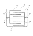
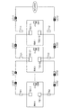
図6は、導電性ゴムシート10に配設されている一対の電極14を説明する図である。図6に示すように、一対の電極14は、全体として櫛状の形状を有し、それぞれ、所定の配線により外部電源(図示せず)と接続している電源接続部141と、第1枝電極部142と4本の第2枝電極部143とを有している。4本の第2枝電極部143は、電源接続部141と結合した第1枝電極部142に略等間隔で略直角に且つ略平行になるように取り付けられている。また、一対の電極14は、4本の第2枝電極部143がそれぞれ互いに平行に対向するように配置されている。このように一対の電極14を配設することにより、導電性ゴムシート10に通電した際に、発熱の均一化が得られる。
FIG. 6 is a diagram illustrating a pair of
(融雪太陽電池パネルの製造方法)
本実施の形態が適用される融雪太陽電池パネルの製造方法としては、例えば、強化ガラス板23上に配線した太陽電池モジュール20、透明樹脂層21,22、バックシート13等と導電性ゴムシート10を積層し、これらを真空中にて加熱し、圧着封止する一体成型加工(ラミネーション)が挙げられる。一体成型加工(ラミネーション)には、通常、太陽電池パネルの製造に使用される真空ラミネーター装置が用いられる。
一体成型加工の条件は、特に限定されないが、本実施の形態では、成型温度は、通常、150℃〜200℃の範囲であり、成型時間は、通常、15分間〜120分間の範囲から適宜選択される。
(Method for manufacturing a snow melting solar cell panel)
As a method for manufacturing a snowmelt solar cell panel to which the present embodiment is applied, for example, the
The conditions of the integral molding process are not particularly limited, but in the present embodiment, the molding temperature is usually in the range of 150 ° C. to 200 ° C., and the molding time is usually appropriately selected from the range of 15 minutes to 120 minutes. Is done.
また、本実施の形態では、真空ラミネーター装置を使用する一体成型加工(ラミネーション)により、導電性ゴムシート10の調製と融雪太陽電池パネルの製造を同時に行うことができる。この場合、前述した未加硫導電性ゴムシート(ゴム成分、遠赤外線放射性物質、導電性フィラーおよび架橋剤等を含むゴム組成物)を、強化ガラス板23、太陽電池モジュール20、透明樹脂層21,22、バックシート13等と積層し、これらを所定の真空ラミネーターを用いて加熱し一体成型加工することにより未加硫導電性ゴムシートを硬化する。これにより、太陽電池モジュール20と導電性ゴムシート10とが圧着封止された融雪太陽電池パネルが製造される。
Moreover, in this Embodiment, the preparation of the
図7(a)および図7(b)は、本実施の形態が適用される融雪太陽電池パネルの他の実施の形態を説明する断面図である。尚、図3に示した融雪太陽電池パネル100と同様な構成については同じ符号を使用し、それらについての詳細な説明は省略する。また、金属製フレーム30、封止材40等は省略している。
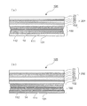
図7(a)に示す融雪太陽電池パネル104は、導電性ゴムシートユニット150上に太陽電池モジュールユニット201を積層した構造を有している。導電性ゴムシートユニット150は、2枚の導電性ゴムシート111,112に上下から挟まれた一対の電極14を有し、さらに、この電極を備えた導電性ゴムシート10は、2枚のバックシート131,132によって挟まれた構造を有している。
太陽電池モジュールユニット201は、導電性ゴムシートユニット150のバックシート132に透明樹脂層21を介して接着された太陽電池モジュール20と、太陽電池モジュール20の表面側に透明樹脂層22を介して太陽電池モジュール20に接着された強化ガラス板23と、が積層されている。
図7(a)に示すように、本実施の形態では、バックシート131と共に導電性ゴムシート111,112を挟んでいるバックシート132は、同時に太陽電池モジュールユニット200の下面に設けられたバックシートとして機能している。尚、これらの導電性ゴムシートユニット150と太陽電池モジュールユニット200とは、所定の真空ラミネーターを用いて封止され、一体構造とされている。
FIG. 7A and FIG. 7B are cross-sectional views for explaining another embodiment of a snow melting solar cell panel to which the present embodiment is applied. In addition, the same code | symbol is used about the structure similar to the snow melting
A snow melting
The solar
As shown in FIG. 7A, in the present embodiment, the
図7(b)に示す融雪太陽電池パネル105は、導電性ゴムシートユニット150上に太陽電池モジュールユニット200が積層された構造を有し、両者は接着剤層24により接着されている。導電性ゴムシートユニット150は、図7(a)に示したものと同様に、一対の電極14を組み込んだ導電性ゴムシート111,112が、2枚のバックシート131,132によって挟まれた構造を有している。
太陽電池モジュールユニット202は、バックシート133に透明樹脂層21を介して接着された太陽電池モジュール20と、太陽電池モジュール20の表面側に透明樹脂層22を介して太陽電池モジュール20に接着された強化ガラス板23とが積層されている。
本実施の形態が適用される融雪太陽電池パネル105の製造方法としては特に限定されない。例えば、導電性ゴムシートユニット150と太陽電池モジュールユニット200の各構成要素を積層し、これらを所定の真空ラミネーターを用いて一体構造とする方法(1回ラミネート);導電性ゴムシートユニット150と太陽電池モジュールユニット200とを、それぞれ所定の真空ラミネーターを用いて製造し、次に、これらを真空ラミネーターを用いて一体構造とする方法(2回ラミネート)等が挙げられる。
The snow-melting
The solar
The manufacturing method of the snowmelt
(融雪パネル)
図7で説明した導電性ゴムシートユニット150は、太陽電池による発電機能を有しない融雪パネルとして、単独で用いることができる。以下、融雪パネルについて説明する。
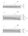
図8(a)〜図8(c)は、本実施の形態が適用される融雪パネルの断面構造を説明する図である。図8(a)に示す融雪パネル151は、バックシート13、電極14を埋め込んだ導電性ゴムシート10及び強化ガラス板23が積層された構造を有している。これらは、所定の真空ラミネーターを用いて封止され、一体構造とされている。
尚、図示しないが、これらのバックシート13、電極14、導電性ゴムシート10及び強化ガラス板23の外周縁部は、図3において説明したように、金属製フレーム30、封止材40等(図3参照)により固定され、一体構造として製造される。
(Snow melting panel)
The conductive
Fig.8 (a)-FIG.8 (c) are the figures explaining the cross-section of the snow melting panel to which this Embodiment is applied. A
Although not shown, the outer peripheral edge portions of the
図8(b)に示す融雪パネル152は、導電性ゴムシートユニット150上に強化ガラス板23が積層された構造を有し、両者は接着剤層25により接着されている。導電性ゴムシートユニット150は、図7(a)に示したものと同様に、一対の電極14を組み込んだ導電性ゴムシート111,112が、2枚のバックシート131,132によって挟まれた構造を有している。図8(a)に示す融雪パネル151と同様に、導電性ゴムシートユニット150と強化ガラス板23は、所定の真空ラミネーターを用いて封止され、さらに、外周縁部は、金属製フレーム30、封止材40等(図示せず)により固定され、一体構造として製造される。
A
図8(a)に示す融雪パネル151と図8(b)に示す融雪パネル152は、いずれも、南側屋根と比較して太陽光の照射が少ない北側屋根に設置され、電極14に電圧を印加することにより導電性ゴムシート10,111,112から放射される遠赤外線により、強化ガラス板23上の積雪を融雪することができる。
Both the
図8(c)に示す融雪パネル153は、一対の電極14を組み込んだ導電性ゴムシート111,112が、2枚のバックシート131,132によって挟まれた構造を有する導電性ゴムシートユニット150を、単独に使用する例である。尚、図示しないが、融雪パネル153の外周縁部は、例えば、合成ゴム、合成樹脂等を用いて封止し、固定される。
融雪パネル153は、例えば、融雪機能が必要とされるロードヒーティング用途、玄関マット用途等に使用することができる。さらに、床暖房用途等に展開することも可能である。
A
The
(発火防止機能)
本実施の形態が適用される融雪太陽電池パネルには、導電性ゴムシートに埋め込まれた電極と外部電源(図示せず)とを結合する所定の配線が配設されている。かかる配線に通電すると、長期間の使用により漏電、短絡(ショート)等が生じる可能性が考えられることから、これらの発生を未然に防止し、発火等を防止する手段が講じられている。
図9は、本実施の形態が適用される融雪太陽電池パネルの発火防止機能を備えた配線系統図である。配線系統図には、ブレーカー制御盤300と複数の融雪太陽電池パネルA0〜F0が示されている。ブレーカー制御盤300内には、MCCB(配線用遮断機)及びMC(電磁接触器)と2個のELCB(漏電遮断機)が設置されている。融雪太陽電池パネルA0〜F0は、それぞれ、導電性ゴムシート及び電極を含む導電性ゴムシートユニットA1〜F1を有し、各導電性ゴムシートユニットA1〜F1は、発火防止用温度ヒューズ(図示せず)を内蔵した2個の端子ボックス(a1,a2)〜(f1,f2)をそれぞれ備えている。これらは、所定の配線を介してAC200Vの外部電源と接続している。
(Fire prevention function)
The snow melting solar cell panel to which the present embodiment is applied is provided with a predetermined wiring for connecting an electrode embedded in a conductive rubber sheet and an external power source (not shown). When such a wiring is energized, there is a possibility that leakage, short-circuiting, etc. may occur due to long-term use. Therefore, measures have been taken to prevent these occurrences and to prevent ignition.
FIG. 9 is a wiring system diagram provided with an ignition prevention function of a snowmelt solar cell panel to which the present embodiment is applied. In the wiring system diagram, a
図10は、図9に示した各導電性ゴムシートユニットが備える端子ボックスを説明する拡大図である。図10中には、AC200Vの外部電源と延長ケーブル(LC11,LC12,〜LC61,LC62)を介して接続された複数の系統(図10では6個:系統1〜6)が示されている。図10に示すように、系統1〜系統5(図示せず)には2端子用の端子ボックス(TB2−11,TB2−12,〜・・・)がそれぞれ配設されており、さらに、図の最も左端に設けた系統6には1端子用の端子ボックス(TB1−1,TB1−2)が配設されている。各系統の端子ボックスの近傍の配線には、発火防止用温度ヒューズ(T11,T12〜T61,T62)が接続されている。尚、本実施の形態では、太陽電池モジュール用の端子ボックス(SB1〜SB6)はAC200Vの外部電源には接続されない。
発火防止用温度ヒューズ(T11,T12〜T61,T62)を端子ボックス(TB2−11,TB2−12,〜・・・),(TB1−1,TB1−2)と接続することにより、導電性ゴムシートが過電流や漏電等で発熱し、過度に温度上昇する場合、発火防止用温度ヒューズが切断し、電源供給が遮断される。本実施の形態では、発火防止用温度ヒューズは、温度約90℃〜130℃程度に昇温すると切断するようになっている。
FIG. 10 is an enlarged view for explaining a terminal box provided in each conductive rubber sheet unit shown in FIG. 9. FIG. 10 shows a plurality of systems (six in FIG. 10:
Conductive rubber by connecting the temperature prevention fuses (T11, T12 to T61, T62) to the terminal boxes (TB2-11, TB2-12, ...), (TB1-1, TB1-2) If the sheet generates heat due to overcurrent, electric leakage, etc. and the temperature rises excessively, the thermal fuse for preventing ignition is cut and the power supply is cut off. In the present embodiment, the thermal prevention thermal fuse is cut when the temperature is raised to about 90 ° C. to 130 ° C.
以下に、実施例に基づき本発明をさらに詳細に説明する。なお、本発明は実施例に限定されるものではない。尚、実施例及び比較例中の部及び%は、特に断らない限り総て重量基準である。 Below, based on an Example, this invention is demonstrated further in detail. In addition, this invention is not limited to an Example. In the examples and comparative examples, all parts and percentages are based on weight unless otherwise specified.
(実施例1〜実施例4、比較例1)
(未加硫導電性ゴムシートの調製)
初めに、混練機として50リットルのニーダーを使用し、表1に示した配合のEPDM組成物を得た。ニーダーの運転条件は、充填率85%、回転数35rpm、混練時間5分間である。次に、これらのEPDM組成物をロール式混練機(日本ロール株式会社製16インチロール)にてシート状に成形し、幅1m×長さ1.5mで、それぞれの厚さ2mm、3mm、8mmの未加硫導電性ゴムシートを得た。
(Examples 1 to 4 and Comparative Example 1)
(Preparation of unvulcanized conductive rubber sheet)
First, a 50 liter kneader was used as a kneader to obtain an EPDM composition having the composition shown in Table 1. The operating conditions of the kneader are a filling rate of 85%, a rotation speed of 35 rpm, and a kneading time of 5 minutes. Next, these EPDM compositions were formed into a sheet shape with a roll-type kneader (16-inch roll manufactured by Nippon Roll Co., Ltd.), 1 m wide × 1.5 m long, and each having a thickness of 2 mm, 3 mm, and 8 mm. An unvulcanized conductive rubber sheet was obtained.
(融雪太陽電池パネルの製造方法)
続いて、太陽電池モジュールと未加硫導電性ゴムシートを含む積層体を、真空ラミネーター(株式会社エヌ・ピー・シー製)により160℃で60分間ラミネート加工し、未加硫導電性ゴムシートを架橋成形するとともに、これらを一体化した融雪太陽電池パネルを成形した。一体化した構造は、以下の通りである。
(Method for manufacturing a snow melting solar cell panel)
Subsequently, the laminate including the solar cell module and the unvulcanized conductive rubber sheet was laminated at 160 ° C. for 60 minutes with a vacuum laminator (manufactured by NPC Corporation), and the unvulcanized conductive rubber sheet was In addition to cross-linking molding, a snow melting solar cell panel in which these were integrated was molded. The integrated structure is as follows.
(構造)
強化ガラス板23/EVA封止材(透明樹脂層22)/セル(太陽電池モジュール20)/EVA封止材(透明樹脂層21)/PETバックシート(バックシート13)/導電性ゴムシート10/断熱シート11
(Construction)
尚、PETバックシート(バックシート13)または断熱シート11と導電性ゴムシート10とは、接着剤(シアノアクリレート系接着剤:東和合成株式会社製)を用いて接着した。さらに、導電性ゴムシート10の両端とほぼ真ん中に電極を設け、導電性ゴムシート10に電気を通電し、遠赤外線効果により融雪する機能を付与した。
尚、比較例として、導電性ゴムシートをクロム線抵抗発熱体ゴムシートに変更し、それ以外は実施例2と同様な操作により太陽電池パネルを作成し、融雪する機能を評価した。
The PET back sheet (back sheet 13) or the
As a comparative example, the conductive rubber sheet was changed to a chrome wire resistance heating element rubber sheet, and a solar cell panel was prepared by the same operation as in Example 2 and the function of melting snow was evaluated.
(融雪評価法)
前述した操作により、導電性ゴムシート10とセル(太陽電池モジュール20)とを一体化して成形した融雪太陽電池パネルについて、以下の手順により融雪評価を行った。尚、パネルのサイズは、横1m、縦1.4mである。
予め、導電性ゴムシート10に通電し、融雪太陽電池パネルを1時間暖めた。次に、強化ガラス板23の上面に一辺3cmの立方体の氷1kgを重ならないように載せ、さらに10分間、導電性ゴムシート10に通電した。続いて、強化ガラス板23上面の氷を回収し、氷の重量(g)の減量分を融雪能力(単位:g)とした。数値が小さいほど、融雪能力が大きいことを示している。
尚、融雪能力が凡そ800gとなるときのワット数を電力(W)として求めた。
(Snow melting evaluation method)
The snow melting evaluation was performed by the following procedure for the snow melting solar cell panel formed by integrating the
In advance, the
In addition, the wattage when the snow melting ability is about 800 g was obtained as electric power (W).
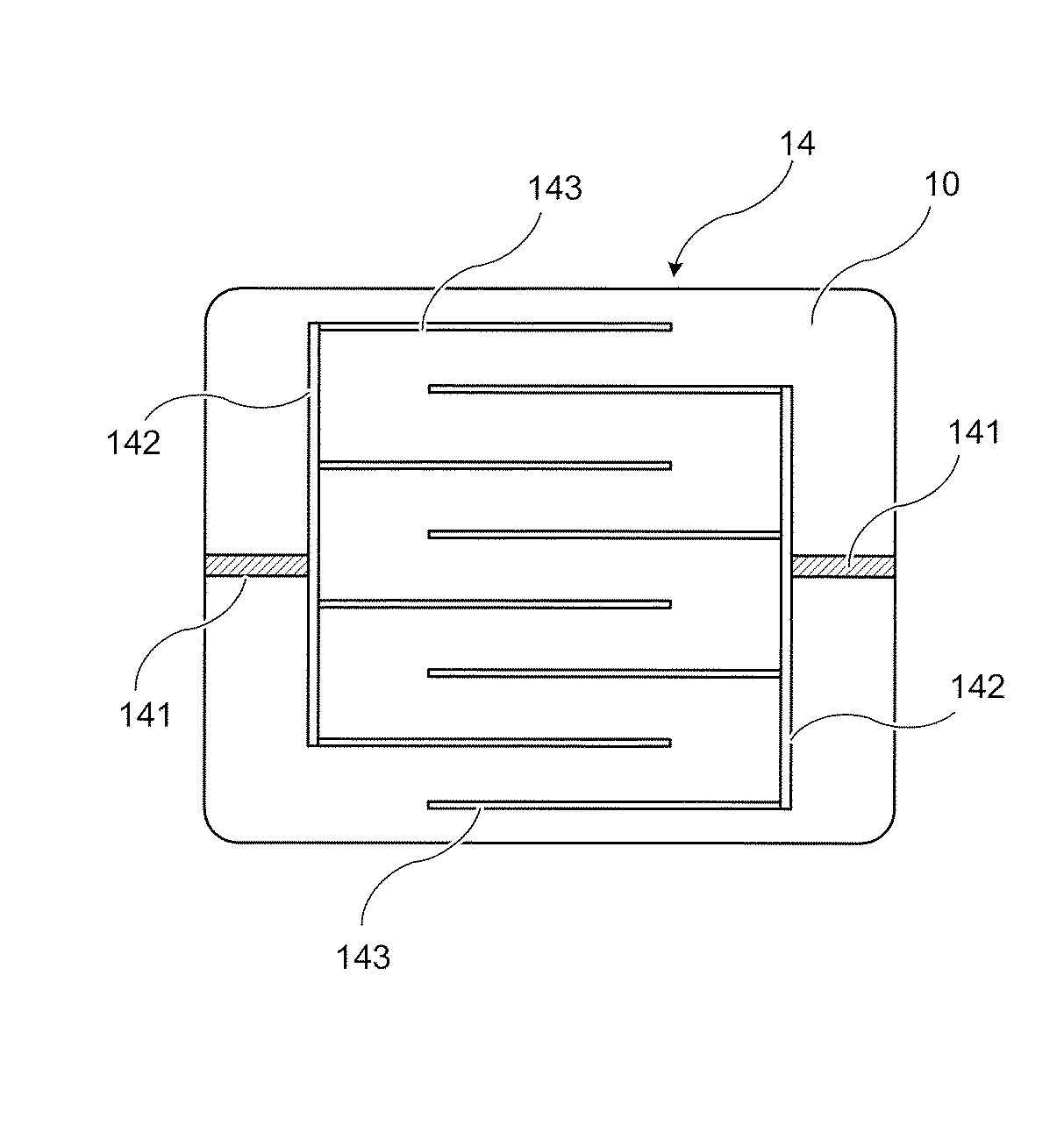
尚、表1の配合成分は以下の通りである。
*(1)EPDM:住友化学社製ES501A
*(2)パラフィン系オイル:出光興産株式会社製PW−90
*(3)過酸化物架橋剤:日本油脂株式会社製パーヘキサ25B
*(4)ニクロム線抵抗発熱体ゴムシート:シリコンラバーヒーター(2枚のシリコンゴムシートの間に、パターン化したニッケル金属抵抗体を配した面状発熱体。)
In addition, the compounding component of Table 1 is as follows.
* (1) EPDM: ES501A manufactured by Sumitomo Chemical Co., Ltd.
* (2) Paraffinic oil: PW-90 manufactured by Idemitsu Kosan Co., Ltd.
* (3) Peroxide crosslinking agent: Perhexa 25B manufactured by NOF Corporation
* (4) Nichrome wire resistance heating element rubber sheet: Silicon rubber heater (A planar heating element in which a patterned nickel metal resistor is disposed between two silicon rubber sheets.)
表1に示す結果から、遠赤外線放射性物質としてケッチェンブラック(実施例1〜実施例4)を配合した導電性ゴムシート10と太陽電池モジュール20を積層した太陽電池パネルは、少ない消費電力で良好な融雪効果が得られることが分かる。
これに対し、ニクロム線抵抗発熱体ゴムシートを用いた場合(比較例1)は、実施例1〜実施例4と同等な融雪効果を得るには、高い消費電力(160W)が必要であることが分かる。
From the results shown in Table 1, the solar cell panel in which the
On the other hand, when the nichrome wire resistance heating element rubber sheet is used (Comparative Example 1), high power consumption (160 W) is required to obtain a snow melting effect equivalent to that of Examples 1 to 4. I understand.
1…融雪太陽電池パネル付き屋根、2…建物、3…接続箱、4…パワーコンディショナ、5…分電盤、6a…売電メータ、6b…買電メータ、7…給電設備、10,111,112…導電性ゴムシート、11…断熱シート、12…遠赤外線反射膜、13,131,132,133…バックシート、14…電極、15,16,17…防湿シート、20…太陽電池モジュール、21,22…透明樹脂層、23…強化ガラス板、24,25…接着剤層、30…金属製フレーム、40…封止材、100,101,102,103,104,105…融雪太陽電池パネル、141…電源接続部、142…第1枝電極部、143…第2枝電極部、150…導電性ゴムシートユニット、151,152,153…融雪パネル、201,202…太陽電池モジュールユニット、300…ブレーカー制御盤
DESCRIPTION OF
Claims (11)
前記導電性ゴムシートの表面側に当該導電性ゴムシートと一体になるように積層された太陽電池モジュールと、を有する
ことを特徴とする融雪太陽電池パネル。 A conductive rubber sheet comprising a rubber component and a far-infrared radioactive material;
A snow melting solar cell panel comprising: a solar cell module laminated on the surface side of the conductive rubber sheet so as to be integrated with the conductive rubber sheet.
前記導電性ゴムシートに配設され所定の外部電源と接続する一対の電極と、を有する
ことを特徴とする融雪パネル。 A conductive rubber sheet comprising a rubber component and a far-infrared radioactive material;
A snow melting panel comprising: a pair of electrodes disposed on the conductive rubber sheet and connected to a predetermined external power source.
前記融雪太陽電池パネルが取り付けられる屋根板と、を有する
ことを特徴とする融雪太陽電池パネル付き屋根。 A conductive rubber sheet obtained by blending a far-infrared radioactive substance into a rubber component, a solar cell module laminated so as to be integrated with the conductive rubber sheet on the surface side of the conductive rubber sheet, and the laminated solar battery module A snowmelt solar cell panel comprising a conductive rubber sheet and a metal frame formed so as to surround the outer peripheral edge of the solar cell module via a sealing material;
And a roof plate to which the snow melting solar cell panel is attached.
Priority Applications (1)
| Application Number | Priority Date | Filing Date | Title |
|---|---|---|---|
| JP2013073951A JP2014040768A (en) | 2012-03-29 | 2013-03-29 | Snow-melting solar battery panel, roof with snow-melting solar battery panel, method of manufacturing snow-melting solar battery panel, and snow-melting panel |
Applications Claiming Priority (5)
| Application Number | Priority Date | Filing Date | Title |
|---|---|---|---|
| JP2012077944 | 2012-03-29 | ||
| JP2012077944 | 2012-03-29 | ||
| JP2012163913 | 2012-07-24 | ||
| JP2012163913 | 2012-07-24 | ||
| JP2013073951A JP2014040768A (en) | 2012-03-29 | 2013-03-29 | Snow-melting solar battery panel, roof with snow-melting solar battery panel, method of manufacturing snow-melting solar battery panel, and snow-melting panel |
Publications (2)
| Publication Number | Publication Date |
|---|---|
| JP2014040768A true JP2014040768A (en) | 2014-03-06 |
| JP2014040768A5 JP2014040768A5 (en) | 2016-05-26 |
Family
ID=50393208
Family Applications (1)
| Application Number | Title | Priority Date | Filing Date |
|---|---|---|---|
| JP2013073951A Pending JP2014040768A (en) | 2012-03-29 | 2013-03-29 | Snow-melting solar battery panel, roof with snow-melting solar battery panel, method of manufacturing snow-melting solar battery panel, and snow-melting panel |
Country Status (1)
| Country | Link |
|---|---|
| JP (1) | JP2014040768A (en) |
Cited By (4)
| Publication number | Priority date | Publication date | Assignee | Title |
|---|---|---|---|---|
| JP2015126180A (en) * | 2013-12-27 | 2015-07-06 | 株式会社 シリコンプラス | Snow melting solar cell panel and snow melting panel |
| JP2018040150A (en) * | 2016-09-07 | 2018-03-15 | 有限会社江部電気 | Snow melting roof structure and snow melting roof structure |
| CN115295649A (en) * | 2022-07-25 | 2022-11-04 | 中国电子科技集团公司第四十八研究所 | Photovoltaic module with snow melting function |
| WO2025077419A1 (en) * | 2023-10-09 | 2025-04-17 | 宁德时代新能源科技股份有限公司 | Photovoltaic assembly, solar cell, electric device, power generation apparatus, preparation method, packaging adhesive film, and use |
Citations (2)
| Publication number | Priority date | Publication date | Assignee | Title |
|---|---|---|---|---|
| JPH01227382A (en) * | 1988-03-04 | 1989-09-11 | Nok Corp | Far infrared ray plane heating body |
| JP2007311635A (en) * | 2006-05-19 | 2007-11-29 | Ecomode:Kk | Snow melting type solar cell module |
-
2013
- 2013-03-29 JP JP2013073951A patent/JP2014040768A/en active Pending
Patent Citations (2)
| Publication number | Priority date | Publication date | Assignee | Title |
|---|---|---|---|---|
| JPH01227382A (en) * | 1988-03-04 | 1989-09-11 | Nok Corp | Far infrared ray plane heating body |
| JP2007311635A (en) * | 2006-05-19 | 2007-11-29 | Ecomode:Kk | Snow melting type solar cell module |
Cited By (4)
| Publication number | Priority date | Publication date | Assignee | Title |
|---|---|---|---|---|
| JP2015126180A (en) * | 2013-12-27 | 2015-07-06 | 株式会社 シリコンプラス | Snow melting solar cell panel and snow melting panel |
| JP2018040150A (en) * | 2016-09-07 | 2018-03-15 | 有限会社江部電気 | Snow melting roof structure and snow melting roof structure |
| CN115295649A (en) * | 2022-07-25 | 2022-11-04 | 中国电子科技集团公司第四十八研究所 | Photovoltaic module with snow melting function |
| WO2025077419A1 (en) * | 2023-10-09 | 2025-04-17 | 宁德时代新能源科技股份有限公司 | Photovoltaic assembly, solar cell, electric device, power generation apparatus, preparation method, packaging adhesive film, and use |
Similar Documents
| Publication | Publication Date | Title |
|---|---|---|
| US6113718A (en) | Method for manufacturing a solar cell module having photovoltaic cell sandwiched between covering materials | |
| EP2640161B1 (en) | Planar heating element and production method for same | |
| EP2144301B1 (en) | Photovoltaic module comprising insulation layer with silane groups | |
| US20100236608A1 (en) | Photovoltaic module with heater | |
| KR20080041652A (en) | Photovoltaic Module with Improved Back Sheet | |
| EP0836233A2 (en) | Solar cell module | |
| JP2014040768A (en) | Snow-melting solar battery panel, roof with snow-melting solar battery panel, method of manufacturing snow-melting solar battery panel, and snow-melting panel | |
| JP2003052185A (en) | Power converter, photovoltaic element module using the same, and power generator | |
| US20170006664A1 (en) | Wet-use plane heater using ptc constant heater-ink polymer | |
| US20180323322A1 (en) | Electrical connectors of building integrable photovoltaic modules | |
| JP5898216B2 (en) | Improved connector and electronic circuit assembly for improved wet insulation resistance | |
| US20140338730A1 (en) | Photovoltaic module with heater | |
| JP2014143321A (en) | Solar cell module | |
| US20110073164A1 (en) | Isobutylene-Based Elastomers in Voltaic Cell Applications | |
| JP6685663B2 (en) | Fever sheet | |
| JP2015176917A (en) | Solar cell module and vehicle member | |
| JPH11216832A (en) | Manufacturing method of laminate | |
| WO2014136580A1 (en) | Solar battery module | |
| JP6439120B2 (en) | Snow melting solar panel | |
| CN222051785U (en) | Curved photovoltaic components and photovoltaic building surfaces | |
| JP6908564B2 (en) | Snow melting panel | |
| JP2014207441A (en) | Solar cell module and vehicle component | |
| US20170317222A1 (en) | Solar cell module | |
| CN117878162A (en) | Curved photovoltaic components | |
| JP2013030734A (en) | Solar cell module |
Legal Events
| Date | Code | Title | Description |
|---|---|---|---|
| A521 | Request for written amendment filed |
Free format text: JAPANESE INTERMEDIATE CODE: A523 Effective date: 20160328 |
|
| A621 | Written request for application examination |
Free format text: JAPANESE INTERMEDIATE CODE: A621 Effective date: 20160328 |
|
| A131 | Notification of reasons for refusal |
Free format text: JAPANESE INTERMEDIATE CODE: A131 Effective date: 20170314 |
|
| A02 | Decision of refusal |
Free format text: JAPANESE INTERMEDIATE CODE: A02 Effective date: 20170919 |