JP2014040738A - Water supply apparatus - Google Patents
Water supply apparatus Download PDFInfo
- Publication number
- JP2014040738A JP2014040738A JP2012183565A JP2012183565A JP2014040738A JP 2014040738 A JP2014040738 A JP 2014040738A JP 2012183565 A JP2012183565 A JP 2012183565A JP 2012183565 A JP2012183565 A JP 2012183565A JP 2014040738 A JP2014040738 A JP 2014040738A
- Authority
- JP
- Japan
- Prior art keywords
- water
- water supply
- pipe
- water discharge
- fire hydrant
- Prior art date
- Legal status (The legal status is an assumption and is not a legal conclusion. Google has not performed a legal analysis and makes no representation as to the accuracy of the status listed.)
- Pending
Links
Images

Landscapes
- Fire-Extinguishing By Fire Departments, And Fire-Extinguishing Equipment And Control Thereof (AREA)
Abstract
【課題】地中に設置された消火栓の出水端に接続し、地上の吐水口に送水を行なう送水装置において、地中型消火栓への取り付け、取外し等の作業を容易にし、斯かる作業における作業者の手間を軽減させることができる送水装置を提供する。
【解決手段】一端が出水端201と接続し、蛇口74に水を送る送水管10と、送水管10の外周面に設けられた把持部40と、送水管10の他端と接続しており、蛇口74を有する吐水部70とを備え、把持部40を用いて消火栓200の出水端201への取り付け・取外し等を行なう。
【選択図】図5[PROBLEMS] To easily attach to and remove from an underground fire hydrant in a water supply device that connects to a water discharge end of a fire hydrant installed in the ground and supplies water to a water outlet on the ground. A water supply device that can reduce the time and effort of a water supply is provided.
One end is connected to a water discharge end 201, and is connected to a water supply pipe 10 for sending water to a faucet 74, a grip portion 40 provided on the outer peripheral surface of the water supply pipe 10, and the other end of the water supply pipe 10. The water discharge part 70 having the faucet 74 is provided, and the holding part 40 is used to attach / remove the fire hydrant 200 to / from the water discharge end 201.
[Selection] Figure 5
Description
本発明は、地中に設置された消火栓の出水端に接続し、地上の吐水口に送水する送水装置に関する。 The present invention relates to a water supply device that is connected to a water discharge end of a fire hydrant installed in the ground and supplies water to a water outlet on the ground.
従来から、震災、火災などの災害時の消火に用いられる水を供給するために消火栓を路上、又は建物の内外に設けてある。しかし、このような消火栓の場合、常時、不特定多数の人が利用可能であることから、いたずらなどによる漏水或いは盗水、又は通行の邪魔となる等のおそれがあった。 Conventionally, fire hydrants have been provided on the road or inside and outside buildings to supply water used for extinction in the event of a disaster such as an earthquake or a fire. However, in the case of such a fire hydrant, since an unspecified number of people can always use it, there has been a risk of water leakage or stealing due to mischief, or obstruction of traffic.
このような問題を解決するために、消火栓を地中に設けた、いわゆる地中型消火栓が普及している。 In order to solve such a problem, a so-called underground fire hydrant in which a fire hydrant is provided in the ground is widely used.
また、特許文献1においては、上端の蛇口に繋がるパイプが上部及び下部に二分されて、上部パイプが上下移動出来るように下部パイプに嵌装されることにより、上部パイプが地上に出没できるように構成された給水栓が開示されている。
Further, in
一方、上述したような、地中型消火栓の場合は、出水口まで地上からは作業者の手が届かない深さに設けられた場合が多いので、該出水口から水を地上まで導く作業は、作業者にとって手間のかかる困難な作業であった。 On the other hand, in the case of underground fire hydrants, as described above, the work is often provided at a depth that the worker cannot reach from the ground up to the water outlet. It was a difficult and labor-intensive work for the operator.
しかしながら、特許文献1に係る給水栓においては、上部パイプが地上に出没できるので、このような問題を解決できるものの、斯かる発明の適用のためには、上述したような構成を必要とすることから、既存設備、すなわち、既に設置されている地中型消火栓には適用できないという問題がある。
However, in the faucet according to
本発明は、斯かる事情に鑑みてなされたものであり、その目的とするところは、地中に設置された消火栓の出水端に接続し、地上の吐水口に送水を行なう送水装置において、一端が前記出水端と接続し、前記吐水口に水を送る送水管と、該送水管の外周面に設けられた把持部と、前記送水管の他端と接続しており、前記吐水口を有する吐水部とを備え、前記把持部を用いて前記消火栓の出水端への取り付け・取外し等を行なうことにより、地中型消火栓への取り付け、取外し等の作業を容易にし、斯かる作業における作業者の手間を軽減させることができる送水装置を提供することにある。 The present invention has been made in view of such circumstances, and an object of the present invention is to connect one end of a fire hydrant installed in the ground and supply water to a ground outlet. Is connected to the water discharge end, is connected to the water supply pipe that sends water to the water discharge port, the grip provided on the outer peripheral surface of the water supply pipe, and the other end of the water supply pipe, and has the water discharge port A water discharge part, and by using the grip part to attach / remove the fire hydrant to / from the water discharge end, it is easy to attach / remove to / from the underground fire hydrant. An object of the present invention is to provide a water supply device capable of reducing labor.
本発明に係る送水装置は、地中に設置された消火栓の出水端に接続し、地上の吐水口に送水を行なう送水装置において、一端が前記出水端と接続し、前記吐水口に水を送る送水管と、該送水管の外周面に設けられた把持部と、前記送水管の他端と接続しており、前記吐水口を有する吐水部とを備えることを特徴とする。 A water supply device according to the present invention is connected to a water discharge end of a fire hydrant installed in the ground, and in a water supply device that supplies water to a ground water discharge port, one end is connected to the water discharge end and sends water to the water discharge port. A water supply pipe, a grip provided on the outer peripheral surface of the water supply pipe, and a water discharge part connected to the other end of the water supply pipe and having the water discharge port are provided.
本発明にあっては、例えば、前記送水装置を消火栓に取り付ける場合、作業者が前記把持部を持って送水管の一端を前記出水端と接続させる作業を行なう。これによって、消火栓の出水端からの水が、前記送水管を介して前記吐水部の吐水口に送水される。 In the present invention, for example, when the water supply device is attached to a fire hydrant, an operator performs the work of holding one end of the water supply pipe with the water discharge end by holding the grip portion. Thereby, the water from the water discharge end of the fire hydrant is supplied to the water outlet of the water discharge section through the water supply pipe.
本発明に係る送水装置は、前記送水管は、前記出水端と嵌着する嵌着部を一端に備え、前記把持部は、前記送水管の長手方向に移動する可動部材を備えており、前記可動部材の移動に応じて、前記嵌着部と前記出水端とが嵌脱するように構成してあることを特徴とする。 In the water supply device according to the present invention, the water supply pipe includes one end of a fitting portion that is fitted to the water discharge end, and the gripping portion includes a movable member that moves in a longitudinal direction of the water supply pipe, The fitting portion and the water discharge end are configured to be fitted and detached according to the movement of the movable member.
本発明にあっては、例えば、前記送水装置を消火栓に取り付け、又は消火栓から取り外す場合、作業者は、前記把持部の可動部材を前記送水管の長手方向に適宜移動させて、前記嵌着部と前記出水端とを嵌着させ、又は離脱させる。 In the present invention, for example, when the water supply device is attached to or removed from the fire hydrant, the operator appropriately moves the movable member of the grip portion in the longitudinal direction of the water supply pipe, and the fitting portion And the water discharge end are fitted or detached.
本発明に係る送水装置は、前記送水管は長手方向に2分割されており、前記一端側の一方が他方を回転可能に保持していることを特徴とする。 In the water supply apparatus according to the present invention, the water supply pipe is divided into two in the longitudinal direction, and one of the one end sides holds the other in a rotatable manner.
本発明にあっては、2分割された送水管の中、前記一方の部分が、前記他方の部分を回転可能に保持しているので、前記他方の部分は前記送水管の軸心を中心に回転することができる。 In the present invention, among the water pipes divided into two, the one part rotatably holds the other part, so the other part is centered on the axis of the water pipe. Can rotate.
本発明に係る送水装置は、前記吐水部は前記送水管の他端に挿入される挿入部を備えており、前記送水管は前記挿入部と嵌脱する外嵌部を備えることを特徴とする。 The water supply device according to the present invention is characterized in that the water discharge portion includes an insertion portion that is inserted into the other end of the water supply tube, and the water supply tube includes an outer fitting portion that fits into and out of the insertion portion. .
本発明にあっては、前記吐水部の挿入部が前記送水管の外嵌部と嵌脱することによって、前記吐水部と前記送水管との接続が行なわれる。 In this invention, the connection part of the said water discharging part and the said water supply pipe | tube is performed because the insertion part of the said water discharging part fits in and removes from the external fitting part of the said water supply pipe | tube.
本発明に係る送水装置は、前記挿入部は前記吐水部から分離可能に構成されていることを特徴とする。 The water supply device according to the present invention is characterized in that the insertion portion is configured to be separable from the water discharge portion.
本発明にあっては、作業者は前記吐水部から前記挿入部を取外し、必要に応じて、他の部品を取り付ける。 In this invention, an operator removes the said insertion part from the said water discharging part, and attaches other components as needed.
本発明によれば、前記送水装置の地中型消火栓への取り付け及び取外しが簡単になり、斯かる作業における作業者の手間を省き、作業時間を短縮させることができる。 According to the present invention, the water supply device can be easily attached to and detached from the underground fire hydrant, the labor of the worker in such work can be saved, and the work time can be shortened.
本発明によれば、前記送水装置は、送水管と吐水部とが着脱できるように構成されているので、その保管及び持ち運びにおいて利便性を高めることができる。 According to the present invention, since the water supply device is configured such that the water supply pipe and the water discharge portion can be attached and detached, convenience in storage and carrying can be improved.
本発明によれば、前記吐水部から前記挿入部を取外しでき、必要に応じて他の部品を取り付けることが出来る。 According to this invention, the said insertion part can be removed from the said water discharging part, and another component can be attached as needed.
以下に、本発明の実施の形態に係る送水装置を図面に基づいて詳述する。 Below, the water supply apparatus which concerns on embodiment of this invention is explained in full detail based on drawing.
(実施の形態1)
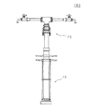
図1は本発明の実施の形態1に係る送水装置100を示す斜視図である。本発明の実施の形態1に係る送水装置100は、地中に設置された消火栓(以下、地中型消火栓という)と接続し、地中型消火栓からの水を地上の吐水口に導く。
(Embodiment 1)
FIG. 1 is a perspective view showing a
送水装置100は、円筒状をなしており、その一端が地中型消火栓の出水端(図示せず)と接続する送水管10と、送水管10を介して地中型消火栓から流れ込む水を吐水する吐水口(例えば、蛇口)を有する吐水部70とを備えている。
The
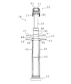
図2は本発明の実施の形態1の送水装置100における、送水管10の外観を示す斜視図である。送水管10は、円筒状であり、前記地中型消火栓からの水を吐水部70に送る通水パイプ30と、通水パイプ30の取扱いに用いられる把持部40と、通水パイプ30の一端部に設けられており、通水パイプ30の一端を前記地中型消火栓の出水端と接続させる消火栓側接続部50と、通水パイプ30の他端部に設けられており、通水パイプ30の他端を吐水部70と接続させる吐水部側接続部20とを備えている。
FIG. 2 is a perspective view showing an appearance of the
吐水部側接続部20は、後述する吐水部70の挿入部を外嵌することにより、通水パイプ30の他端部と吐水部70とを接続させる。吐水部側接続部20は、前記挿入部を外嵌する外嵌部21を有しており、外嵌部21及び前記挿入部はいわゆるクランプ機構による接続固定機構をなしている。換言すれば、外嵌部21は、前記クランプ機構における受口であり、前記挿入部は挿口である。
The water discharge part
すなわち、外嵌部21は、先端に前記挿入部が挿入される挿入口22が形成され、前記挿入部の外径と略等しい内径を有しており、外周面に、斯かる接続固定機構を操作する操作レバー23が設けられている。例えば、前記挿入部が挿入口22を介して外嵌部21内に挿入された場合、作業者は操作レバー23を操作することにより、外嵌部21の内径を狭め、外嵌部21(通水パイプ30の他端部)と、前記挿入部(吐水部70)とを接続させることができる。斯かる接続固定機構はそれ自体公知の技術であり、詳しい説明を省略する。
That is, the
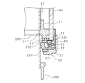
消火栓側接続部50(嵌着部)は通水パイプ30の一端部の外周面に周設されており、いわゆる差込式金具機構を用いて通水パイプ30の一端を前記地中型消火栓の出水端と接続させる。図3は本発明の実施の形態1の送水装置100における、消火栓側接続部50の要部構成を示す断面図である。説明の便宜上、送水装置100が消火栓に接続された場合を例にあげて説明する。図中、200は消火栓を示している。
The fire hydrant side connection part 50 (fitting part) is provided around the outer peripheral surface of one end part of the
消火栓側接続部50は、消火栓200の出水端201の先端が当接する当接部51と、当接部51の内側に設けられたOリング53と、当接部51内に挿入された出水端201を係止する係止爪56と、係止爪56を通水パイプ30の径方向外側に押し付ける押し輪52と、係止爪56を通水パイプ30の径方向内側に押し付けるバネ55と、これらを収容する収容輪57と、収容輪57の外周面に取り付けられ、収容輪57を保護する保護タイヤ54とを備えている。
The fire hydrant
当接部51は、円筒状をなしており、一端側には消火栓200の出水端201が挿入される開口を有し、他端側には通水パイプ30の一端が内嵌されている。当接部51は、前記開口側の内径が出水端201の先端部の外径と略等しい。また、当接部51は、出水端201の先端に形成された出水口203の縁と当接する当接面511を形成しており、出水端201の当接部51内への挿入の際、当接面511及びOリング53によって、適宜その位置が調整される。
The
一方、出水端201には、係止爪56との係合のために、その外周面に段差202が設けられている。係止爪56は、縦断面視横倒れL字状をなしており、その一端が段差202と当接することによって係合し、出水端201を固定する。また、係止爪56は、押し輪52及びバネ55によって、通水パイプ30の径方向の外側又は内側に摺動するように構成されている。更に、係止爪56は、他端に、通水パイプ30の中心から外側に向けて傾斜した傾斜面561が形成されており、傾斜面561が、後述する押し輪52の傾斜面521と当接するように構成されている。
On the other hand, the
バネ55は、係止爪56及び収容輪57の内壁の間に介在しており、常に、係止爪56を通水パイプ30の径方向の内側に押し付ける。すなわち、出水端201が当接部51内に挿入された場合、バネ55によって係止爪56が通水パイプ30の径方向の内側に摺動し、上述した係合が行なわれる。
The
押し輪52は、後述する引上ロッド43の一端に固定されており、当接部51の外周面及び収容輪57の内壁の間に挟持されている。従って、引上ロッド43が上下方向(通水パイプ30の長手方向)に移動する際、当接部51の外周面及び収容輪57の内壁に案内されて押し輪52も共に上下方向に移動する。
The
また、押し輪52は、係止爪56の傾斜面561に対応する傾斜面521を有しており、押し輪52の傾斜面521及び係止爪56の傾斜面561は常に当接するように構成されている。これによって、押し輪52が上方向に移動する際、係止爪56が通水パイプ30の径方向の外側に押し付けられる。
The
すなわち、引上ロッド43の上方向への移動に応じて、押し輪52も共に上方向に移動するが、この際、押し輪52の傾斜面521及び係止爪56の傾斜面561の間に摺動が生じる。しかし、当接部51の外周面及び収容輪57の内壁によって、押し輪52は上方向への移動のみに制限されるので、係止爪56に対しては傾斜面561を介して通水パイプ30の径方向の外側に向かう押圧力が働き、係止爪56を斯かる方向に摺動させる。
That is, according to the upward movement of the pull-up
通水パイプ30は、例えば、ステンレススチールからなる円筒状の直管であり、前記一端部を含む下部パイプ32と、前記他端部を含む上部パイプ31とに2分割されている。下部パイプ32は上部パイプ31の外径より少し大きい内径を有しており、上部パイプ31は一端部が下部パイプ32に内嵌されて、その軸心を中心に回転可能に保持されている。
The
従って、吐水部側接続部20に吐水部70が接続された状態においても、通水パイプ30の軸心を中心に吐水部70が自由に回転でき、斯かる作業における使い勝手が向上される。また、後述するように、吐水部70に代わって消火ホースを付けて使用する場合は、斯かる自由回転によって、前記消火ホースにかかる負担(負荷)を軽減でき、該消火ホースにおける変形の発生を未然に防止できる。
Therefore, even in the state where the
通水パイプ30の長手方向における中間部には、例えば、通水パイプ30の取付・取外に用いられ、また消火栓側接続部50を操作する把持部40が設けられている。把持部40は、通水パイプ30の外周面に対称配置された固定棒41,41及び可動棒42,42を有している。
At a middle portion in the longitudinal direction of the
固定棒41は、通水パイプ30の外周面に固定されており、通水パイプ30の径方向の外側に延びる棒状部材である。作業者は固定棒41を用いて、持ち運び等送水管10の取扱いを行なう。
The fixed
可動棒42(可動部材)は、通水パイプ30の外周面上を摺動可能に設けられた円筒状の上下動輪44の外周面に固定されている。すなわち、上下動輪44の内径は通水パイプ30の外径と略同じであり、上下動輪44は通水パイプ30の外周面上を上下方向に摺動できる。また、上下動輪44の外周面には、可動棒42,42が相互対称配置されており、例えば、作業者が可動棒42,42を握って上下方向に移動させた場合、上下動輪44によって案内される。
The movable rod 42 (movable member) is fixed to the outer peripheral surface of a cylindrical vertical moving
また、可動棒42,42は、基部45に、換言すれば通水パイプ30側端部に、押し輪52を上方向に引き上げる引上ロッド43が夫々連結されている。引上ロッド43は、例えば、直線状の細い金属棒であり、一端が押し輪52に固定され、他端が可動棒42の基部45に固定されている。より詳しくは、引上ロッド43の他端が可動棒42を径方向に貫通して上方に突出しており、引上ロッド43の斯かる端部を可動棒42の基部45で、例えば、ナットを用いて固定している。
The
従って、作業者が可動棒42,42及び固定棒41,41を共に把持した場合、可動棒42,42が上方向に移動し、これに応じて、引上ロッド43,43が上方向に引き上げられ、押し輪52も共に上方向に移動する。この際、上述したように、係止爪56に対しては通水パイプ30の径方向の外側に向かう力が働き、係止爪56が通水パイプ30の径方向の外側に摺動し、消火栓200の出水端201と、消火栓側接続部50との係止が解除される。
Therefore, when the operator holds both the
なお、把持部40と、消火栓側接続部50との間には、引上ロッド43の上下動を案内する案内輪60が設けられている。案内輪60は通水パイプ30の外周面上に設けられており、所定の長さを有する円筒状をなしている。また、案内輪60は、長さ方向に貫通する貫通穴を2つ有しており、夫々の貫通穴に引上ロッド43が挿通されている。これによって、引上ロッド43の上下動が案内される。
A
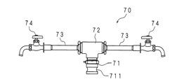
図4は本発明の実施の形態1の送水装置100における、吐水部70の外観を示す斜視図である。吐水部70は、送水管10の吐水部側接続部20と接続する挿入部71と、挿入部71と接続される分岐用継手72、分岐用継手72にその一端が接続される連結パイプ73,73と、連結パイプ73,73の他端に接続された蛇口74,74(吐水口)とを備えている。
FIG. 4 is a perspective view showing an appearance of the
挿入部71は、円筒状をなしており、その一端部が吐水部側接続部20の外嵌部21に挿入されて外嵌されることにより、上述したようなクランプ機構による接続固定が行なわれる。換言すれば、挿入部71は、前記クランプ機構における挿口である。挿入部71の前記一端部の外周面には、斯かるクランプ機構のために、凹溝711が形成されている。
The
一方、挿入部71の他端部には雄ネジ加工が施されており、これを用いて分岐用継手72が螺着される。換言すれば、吐水部70は、挿入部71が分離可能に構成されている。
On the other hand, the other end portion of the
分岐用継手72は、T字状をなしており、3つの開口を有している。3つの開口の中、1つには、上述したように、挿入部71の他端部との螺合のために、その内側に雌ねじ加工が施されている。他の2つの開口は、夫々、連結パイプ73,73を介して蛇口74,74に連結されている。
The branch joint 72 is T-shaped and has three openings. Of the three openings, one is internally threaded for screwing with the other end of the
すなわち、分岐用継手72の他の2つの開口には、夫々、連結パイプ73,73の一端が、例えば、螺嵌されている。また、連結パイプ73,73の他端には、夫々蛇口74,74が螺嵌されている。
That is, one end of each of the
以上の構成によって、消火栓200からの水は、送水管10を介して、吐水部70に流れ込み、蛇口74から吐水される。
With the above configuration, the water from the
以下に、本発明の実施の形態1に係る送水装置100の消火栓200への取り付け及び取外しについて説明する。図5は本発明の実施の形態1に係る送水装置100を、消火栓200に取り付けた状態の一例を表す例示図である。
Below, the attachment and removal to the
作業者は、把持部40を持って、送水管10の消火栓側接続部50を、消火栓200の出水端201に合わせた後、そのまま把持部40を押し下げる。この際、出水端201が消火栓側接続部50(当接部51)内に挿入され、出水口203の縁が当接部51の内側(当接面511)と当接した場合、バネ55によって係止爪56が通水パイプ30の径方向の内側に摺動し、上述したように、出水端201及び消火栓側接続部50の係合が行なわれる。詳しい事項は、既に説明しており、詳しい説明を省略する。以降、作業者は消火栓200のバルブ204を開け、蛇口74,74に水が流れる。
The operator holds the
一方、送水装置100を取り外す場合、作業者は、消火栓200のバルブ204を閉じた後、可動棒42,42及び固定棒41,41を共に把持して可動棒42,42を上方向に移動させる。これに応じて、引上ロッド43,43が上方向に引き上げられ、押し輪52も共に上方向に移動する。これによって、係止爪56が通水パイプ30の径方向の外側に摺動し、消火栓200の出水端201と、消火栓側接続部50との係止が解除され、送水装置100を分離できる。
On the other hand, when removing the
本発明に係る送水装置100は以上のような構成を有するので、地中型消火栓への取り付け及び取外しが簡単であり、斯かる作業における作業者の手間を省き、作業時間を短縮させることができる。
Since the
また、本発明に係る送水装置100は、送水管10と吐水部70とが着脱できるように構成されているので、その保管及び持ち運びにおいて利便性を高めることができる。
Moreover, since the
(実施の形態2)
実施の形態1においては、吐水口として、送水装置100が蛇口74,74を備える場合を例として説明したが、本発明はこれに限るものでなく、例えば、吐水口として、消火ホースを着けることも可能である。
(Embodiment 2)
In
上述したように、吐水部70は、挿入部71が分離可能に構成されている。従って、挿入部71の一端部が送水管10(吐水部側接続部20)と接続された状態において、挿入部71の他端部に分岐用継手72でなくいわゆるエルボを接続させ、該エルボに消火ホースを取り付ける。
As described above, the
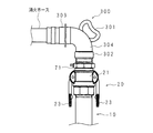
図6は本発明の実施の形態2に係る送水装置100に取り付けられるエルボの一例を示す例示図である。図中、300は斯かるエルボを示す。
FIG. 6 is an exemplary view showing an example of an elbow attached to the
エルボ300は、その屈曲部304に設けられており、取扱いに用いられるハンドル301と、一端部に設けられており、挿入部71の他端部と接続する接続端302と、他端部に設けられており、消火ホースと接続するホース接続金具303とを備えている。
The
接続端302の内周面には、挿入部71の他端部の雄ネジに対応する雌ネジ加工が施されており、これを用いてエルボ300が挿入部71に螺着される。
The inner peripheral surface of the
また、屈曲部304は、接続端302側の端部が接続端302に内嵌されており、接続端302の軸心を中心に回転可能に構成されている。例えば、作業者がホース接続金具303に消火ホースを取り付けて、消火作業を行なう場合、必要に応じてハンドル301を適宜操作して屈曲部304を回転させ、ホース接続金具303の向きを変えることが出来る。
Further, the
これによって、前記消火ホースにかかる負担(負荷)が軽減され、該消火ホースにおける変形の発生を未然に防止できる。 Thereby, the load (load) applied to the fire hose can be reduced, and deformation of the fire hose can be prevented in advance.
以上においては、エルボ300がいわゆる90度エルボである場合を例として説明したがこれに限るものでなく、例えば、45度エルボであっても良い。
In the above description, the case where the
また、実施の形態1においては、分岐用継手72の両端側に2つの蛇口74,74が設けられた場合を例として説明したがこれに限るものでなく、2つ以上の蛇口74を備えるように構成しても良い。例えば、複数の蛇口74,74,…74を有する所定のユニットを分岐用継手72に接続することができる。
Moreover, in
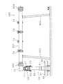
図7は本発明の実施の形態2に係る送水装置100に取り付けられるユニットの一例を示す例示図である。図中、400は斯かるユニットを示す。
FIG. 7 is an exemplary view showing an example of a unit attached to the
ユニット400は、分岐用継手72に接続するための接続金具402と、接続金具402がその一端に設けられた給水管401と、給水管401に取り付けられた複数の蛇口74,74,…74と、給水管401の下側に設けられており、倒立V字状の支脚403,403と、接続金具402に対応しており、他のユニット400との接続を行なう接続金具404とを備えている。
The
作業者は、ユニット400の接続金具402を分岐用継手72の前記他の2つの開口の一方、又は両方に接続することにより、蛇口74の数を増やすことができる。
The operator can increase the number of the
また、作業者は、分岐用継手72にユニット400が接続されている状態において、該ユニット400の接続金具404に、他のユニット400の接続金具402を接続することにより、蛇口74の数を更に増やすことができると共に、必要に応じて遠距離まで水を送ることが出来る。
In addition, in a state where the
実施の形態1と同様の部分については、同一の符号を付して詳細な説明を省略する。 The same parts as those in the first embodiment are denoted by the same reference numerals, and detailed description thereof is omitted.
10 送水管
42 可動棒
40 把持部
20 吐水部側接続部
30 通水パイプ
50 消火栓側接続部
70 吐水部
71 挿入部
74 蛇口
100 送水装置
200 消火栓
201 出水端
DESCRIPTION OF
Claims (5)
一端が前記出水端と接続し、前記吐水口に水を送る送水管と、
該送水管の外周面に設けられた把持部と、
前記送水管の他端と接続しており、前記吐水口を有する吐水部と
を備えることを特徴とする送水装置。 In a water supply device that connects to the outlet of a fire hydrant installed in the ground and supplies water to the ground outlet,
One end is connected to the water discharge end, and a water pipe that sends water to the water outlet,
A gripping portion provided on the outer peripheral surface of the water pipe;
A water supply device comprising: a water discharge portion connected to the other end of the water supply pipe and having the water discharge port.
前記把持部は、前記送水管の長手方向に移動する可動部材を備えており、
前記可動部材の移動に応じて、前記嵌着部と前記出水端とが嵌脱するように構成してあることを特徴とする請求項1に記載の送水装置。 The water pipe is provided at one end with a fitting portion to be fitted with the water discharge end,
The grip portion includes a movable member that moves in a longitudinal direction of the water pipe,
The water feeding device according to claim 1, wherein the fitting portion and the water discharge end are configured to be fitted and detached according to the movement of the movable member.
前記送水管は前記挿入部と嵌脱する外嵌部を備えることを特徴とする請求項1から3の何れか一つに記載の送水装置。 The water discharge part comprises an insertion part inserted into the other end of the water pipe,
The water supply device according to any one of claims 1 to 3, wherein the water supply pipe includes an outer fitting portion that fits into and out of the insertion portion.
Priority Applications (1)
| Application Number | Priority Date | Filing Date | Title |
|---|---|---|---|
| JP2012183565A JP2014040738A (en) | 2012-08-22 | 2012-08-22 | Water supply apparatus |
Applications Claiming Priority (1)
| Application Number | Priority Date | Filing Date | Title |
|---|---|---|---|
| JP2012183565A JP2014040738A (en) | 2012-08-22 | 2012-08-22 | Water supply apparatus |
Publications (1)
| Publication Number | Publication Date |
|---|---|
| JP2014040738A true JP2014040738A (en) | 2014-03-06 |
Family
ID=50393183
Family Applications (1)
| Application Number | Title | Priority Date | Filing Date |
|---|---|---|---|
| JP2012183565A Pending JP2014040738A (en) | 2012-08-22 | 2012-08-22 | Water supply apparatus |
Country Status (1)
| Country | Link |
|---|---|
| JP (1) | JP2014040738A (en) |
Cited By (3)
| Publication number | Priority date | Publication date | Assignee | Title |
|---|---|---|---|---|
| CN105862986A (en) * | 2016-06-08 | 2016-08-17 | 江苏赛达电子科技有限公司 | Antitheft fire hydrant |
| JP6039021B1 (en) * | 2015-07-31 | 2016-12-07 | ヨネ株式会社 | Structure for checking the connection of standpipe to fire hydrant |
| DE102017010486A1 (en) * | 2017-07-05 | 2019-01-10 | SWN Stadtwerke Neumünster GmbH | Standpipe with quick coupling |
-
2012
- 2012-08-22 JP JP2012183565A patent/JP2014040738A/en active Pending
Cited By (3)
| Publication number | Priority date | Publication date | Assignee | Title |
|---|---|---|---|---|
| JP6039021B1 (en) * | 2015-07-31 | 2016-12-07 | ヨネ株式会社 | Structure for checking the connection of standpipe to fire hydrant |
| CN105862986A (en) * | 2016-06-08 | 2016-08-17 | 江苏赛达电子科技有限公司 | Antitheft fire hydrant |
| DE102017010486A1 (en) * | 2017-07-05 | 2019-01-10 | SWN Stadtwerke Neumünster GmbH | Standpipe with quick coupling |
Similar Documents
| Publication | Publication Date | Title |
|---|---|---|
| US12049747B2 (en) | Shower bar system | |
| US9027969B2 (en) | Pipe quick release structure | |
| EP3530822A1 (en) | Device for quickly mounting and quickly detaching faucet on countertop | |
| HUT76957A (en) | Interlocking multipurpose airtool | |
| JP2014040738A (en) | Water supply apparatus | |
| KR101454202B1 (en) | Device for blocking hole of pipe | |
| KR101721067B1 (en) | A faucet | |
| US20100170579A1 (en) | Quick release device for faucets | |
| KR101798112B1 (en) | Connector of gas hose | |
| KR20170054122A (en) | Fitting Apparatus for water purifier | |
| KR20190052686A (en) | Drinking water coupling with pollution protection | |
| US7272971B1 (en) | Quick-connect pressure test system | |
| CN104930236A (en) | Universal faucet | |
| JP7002216B2 (en) | Machino style mouthpiece for plumbing equipment | |
| KR101126432B1 (en) | System for removal of a brach feed pipe and method for removal of a brach feed pipe using the same | |
| EP3505304B1 (en) | Device set for installing a sensor unit in a pressurised fluid conduit or for removing the sensor unit and method for same | |
| JPH1073195A (en) | Faucet fittings | |
| CN211315392U (en) | Double-channel pipe-in-pipe and water supply equipment adopting same | |
| JP2007056942A (en) | Check valve holding device | |
| JP6546740B2 (en) | Plug body | |
| ITMI20090993A1 (en) | QUICK COUPLING DEVICE FOR HYDRAULIC PIPES | |
| JP2007252744A (en) | Fitting device for sprinkler head | |
| ITMI20120301U1 (en) | QUICK COUPLING DEVICE FOR HYDRAULIC PIPES | |
| JPH10292452A (en) | Hydrant | |
| JPH09268615A (en) | Faucet inside joint |