JP2014019319A - Vehicle seat - Google Patents
Vehicle seat Download PDFInfo
- Publication number
- JP2014019319A JP2014019319A JP2012160420A JP2012160420A JP2014019319A JP 2014019319 A JP2014019319 A JP 2014019319A JP 2012160420 A JP2012160420 A JP 2012160420A JP 2012160420 A JP2012160420 A JP 2012160420A JP 2014019319 A JP2014019319 A JP 2014019319A
- Authority
- JP
- Japan
- Prior art keywords
- skin material
- seat
- conductive
- conductive skin
- groove
- Prior art date
- Legal status (The legal status is an assumption and is not a legal conclusion. Google has not performed a legal analysis and makes no representation as to the accuracy of the status listed.)
- Pending
Links
Images


Landscapes
- Seats For Vehicles (AREA)
Abstract
Description
本発明は、乗り物用シートに関する。より詳しくは、少なくとも一部が導電性繊維を含む導電性表皮材で表装された乗り物用シートに関する。 The present invention relates to a vehicle seat. More specifically, the present invention relates to a vehicle seat that is at least partially covered with a conductive skin material containing conductive fibers.
従来、この種のシートとして、導電性繊維を含む導電性表皮材で着座面中央を表装し、導電性繊維の静電容量からシートへの着座の有無を判別するセンサが構成されているものがある。このようなシートでは、一般に、導電性表皮材の端部にて、導電性繊維に接続部材が接続されており、該接続部材を介して導電性繊維が静電容量検出器に接続されている。例えば、特許文献1においては、図4に示されるように、シートクッション101を表装するシートカバー111は、座面中央のメイン天板部103を表装する部分が導電性表皮材113で構成されており、その左右の端部は、天板サポート部105を表装する他の表皮材115と縫合されている(縫い目113s)。そして、縫い代113nに接続部材としての銅テープ117が貼付されることで、導電性表皮材113に左右方向に沿って織り込まれた導電性繊維と銅テープ117とが電気的に接続されている。導電性表皮材113と他の表皮材115との縫合部には吊り布121も縫着され、その先端にワイヤ121wが保持されており、ワイヤ121wは、シートパッド122に形成された溝部123の底に埋設されたインサートワイヤ125に係止されている。それにより、導電性表皮材113と他の表皮材115との縫合部が溝部123に吊り込まれ、銅テープ(接続部材)117が貼付された導電性表皮材113の縫い代113nは溝部123に収容されている。このように、接続部材がシートパッドの溝部に収容される構成によれば、着座者に接続部材による違和感を生じにくい。
Conventionally, as this type of seat, there is a sensor configured to cover the seating surface center with a conductive skin material containing conductive fibers, and to determine the presence or absence of seating on the sheet from the capacitance of the conductive fibers. is there. In such a sheet, generally, a connection member is connected to the conductive fiber at the end of the conductive skin material, and the conductive fiber is connected to the capacitance detector via the connection member. . For example, in
特許文献1のように、導電性表皮材113中の導電性繊維に対して、溝部123内で接続部材(銅テープ117)が接続される場合、導電性繊維は、溝部123の内外で確実に導通している必要がある。しかしながら、従来の吊り込み構造においては、シートクッション101に乗員が着座するたびに、導電性表皮材113が溝部123の開口付近で繰り返し屈伸させられやすく、溝部123の内外で導電性繊維が断線するおそれがあった。というのは、図4に示されるように、導電性表皮材113は、メイン天板部103ではシートパッド122の表面に沿って配され、その端部は溝部123の開口にてシートパッド122の表面から浮いた状態となり、溝部123の略中央に吊り込まれている。そのため、図4に二点鎖線で示されるように、着座者Hの荷重により天板メイン部103が凹むと、その端部のシートパッド122の表面から浮いた部分が弛んで折れやすく、導電性繊維が疲労しやすいためである。
As in
そこで、本発明の課題は、導電性表皮材の端部をシートパッドの溝部に吊り込むにあたり、溝部の開口付近での導電性表皮材の折れを抑制することにある。 Accordingly, an object of the present invention is to suppress the breaking of the conductive skin material in the vicinity of the opening of the groove portion when the end portion of the conductive skin material is suspended in the groove portion of the seat pad.
本発明は、着座面を形作るシートパッドと、該シートパッドを被覆するシートカバーとを備え、前記シートパッドの前記着座面を形作る面には、着座者の荷重を直接受け止めることのできる面状部と、該面状部より凹んだ溝部と、が形成されており、前記シートカバーは少なくとも一部が導電性繊維を含む導電性表皮材で構成され、該導電性表皮材は、前記シートパッドの面状部を被覆し、その端部が前記溝部に吊り込まれている乗り物用シートであって、前記導電性表皮材は、前記面状部を被覆する部分から少なくとも前記溝部への吊り込み基点までは、前記シートパッドの外形に沿った状態とされていることを特徴とする。 The present invention includes a seat pad that forms a seating surface and a seat cover that covers the seat pad, and a surface portion that can directly receive a seated person's load on the surface that forms the seating surface of the seat pad. And a groove portion recessed from the planar portion, and the seat cover is formed of a conductive skin material at least partially including conductive fibers, and the conductive skin material is formed of the seat pad. A vehicle seat that covers a planar portion and whose end is suspended in the groove portion, wherein the conductive skin material is a suspension base point from the portion covering the planar portion to at least the groove portion Up to this point, the seat pad is in a state along the outer shape of the seat pad.
かかる乗り物用シートによれば、導電性表皮材は、溝部の開口付近でもシートパッドから浮いていないため、着座が繰り返されても折れにくい。そのため、導電性表皮材に含まれる導電性繊維が疲労しにくく、断線しにくい。 According to such a vehicle seat, since the conductive skin material does not float from the seat pad even near the opening of the groove portion, it is difficult to break even if seating is repeated. Therefore, the conductive fibers contained in the conductive skin material are not easily fatigued and are not easily disconnected.
その一実施形態として、前記導電性表皮材は、その端部に吊り布が縫着されており、該吊り布の先端が前記溝部の底部に係止されることで、前記吊り布の縫着部を吊り込み基点として前記溝部に吊り込まれており、前記溝部における前記吊り布の先端が係止される前記底部の幅方向位置は、前記導電性表皮材で被覆された前記面状部側の側壁の最も張り出した位置よりも、前記導電性表皮材で被覆された前記面状部寄りにずれた位置であることを特徴とするものがある。この場合、導電性表皮材をシートパッドの外形に、ぴたりと沿わせやすい。 As one embodiment, the conductive skin material has a hanging cloth sewn at the end thereof, and the leading end of the hanging cloth is locked to the bottom of the groove portion, so that the hanging cloth is sewn. The bottom portion of the groove, where the tip of the suspension cloth is locked, is suspended from the surface of the planar portion covered with the conductive skin material. There is one characterized in that it is a position that is shifted closer to the planar portion covered with the conductive skin material than a position at which the side wall of the side wall protrudes most. In this case, it is easy to fit the conductive skin material along the outer shape of the seat pad.
また、前記溝部の前記導電性表皮材で被覆された前記面状部側の側壁が、該溝部の内方へ膨らむ円弧形状であると、導電性表皮材をよりぴたりとシートパッドの外形に沿わせやすい。 Further, when the side wall of the groove portion covered with the conductive skin material has an arc shape that swells inward of the groove portion, the conductive skin material is more closely aligned with the outer shape of the seat pad. Easy to put.
本発明によれば、導電性表皮材の端部をシートパッドの溝部に吊り込むにあたり、溝部の開口付近での導電性表皮材の折れを抑制することができる。 According to the present invention, when the end portion of the conductive skin material is suspended in the groove portion of the seat pad, the breakage of the conductive skin material in the vicinity of the opening of the groove portion can be suppressed.
<実施形態1>
以下、図1、2を参照しながら、本発明の一実施形態について説明する。図1に示されるように、本実施形態に係る乗り物用シート11は、座面13aを構成するシートクッション13、背凭れ面15aを構成するシートバック15及びヘッドレスト17を備えている。本実施形態は、本発明をシートクッション13に適用した実施形態の一例である。なお、本明細書において、シートの前後左右は、シートに通常の着座姿勢にて着座した乗員からみた方向として示している。
<
Hereinafter, an embodiment of the present invention will be described with reference to FIGS. As shown in FIG. 1, the
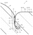
シートクッション13は、シートフレーム(図示省略)にシートパッド21が被せ付けられて座面13aの外形が形作られている。この構成については、従来のシートから変更を要しない。図2に示されるように、座面13aの外形を形作るシートパッド21の上面は、着座者の荷重を直接受け止め得る面状部22と、該面状部22から凹んで形成された溝部27とを有する。面状部22は、主として着座者の荷重を支える中央位置は略平らなメイン天板部23を構成し、両側部位置は盛り上がったサイドサポート部25,25を構成しており、座面13aは、着座者を包み込むように保持することのできる形状となっている。溝部27は、メイン天板部23と各サイドサポート部25,25との境界において、シートクッション13の前後方向に延びて形成されている。溝部27は、その長手方向に直交する断面でみて概ねL字形状の空洞として形成されている。溝部27の開口付近は、メイン天板部23又はサイドサポート部25と緩やかなカーブを形成して繋がり、対向する側壁29、31は幅が深さ方向に漸次が狭くなっており、底部にはメイン天板部23に潜り込む方向に張り出す潜入部33が延設されている。潜入部33の奥部には、溝部27の長手方向に沿って、インサートワイヤ35が埋設されている。シートパッド21は、その外表面に沿うシートカバー41で被覆されており、該シートカバー41は、溝部27に吊り込まれている。その吊り込み構造については後述する。
The
シートカバー41は、表皮材を裁断してなるカバーピース(表皮材の小片)を複数縫合して袋状をなしている。図1に示されるように、シートカバー41の座面13aを表装する部分は、シートパッド21のメイン天板部23を被覆する中央カバーピース45と、サイドサポート部25,25を被覆するサイドカバーピース47,47とが縫合されて形成されている。メイン天板部23を被覆する中央カバーピース45は、導電性表皮材43を裁断したものであり、サイドサポート部25,25を被覆するサイドカバーピース47,47は、導電性を有しない表皮材を裁断したものである。これに、更に、シートパッド21の側面を被覆するカバーピースが縫合されて袋状のシートカバー41が形成されており、シートパッド21に被せ付けられている。
The
中央カバーピース45を構成する導電性表皮材43とは、導電性繊維43sを含む表皮材である。本実施形態では、導電性表皮材43として導電性繊維43sが織り込まれた織物を用いている。導電性繊維43sとは、導電性を有する繊維である。導電性繊維43sの材質や形態は限定されず、例えば、銅やステンレス等の金属や合金からなる繊維、芯となる繊維の表面に金属や合金をめっきしてなる繊維あるいはカーボンファイバー等が挙げられる。これらの繊維は単体で用いても、或いは他の繊維と撚り合わされて用いてもよい。なお、本発明での表皮材とは、シートクッション13の外表面に露出する表面材単体で構成されているものと、表面材の裏面に薄い発泡ウレタンシートなどが積層されてなる複合体との双方を含む。表面材は、例えば、織物、編物、不織布、皮・合皮等からなる。導電性表皮材43に導電性繊維43sが含まれる形態としては、例えば、表面材に導電性繊維43sが織り込まれ、編み込まれ、縫い込まれ或いは接着されているものが挙げられる。
The
中央カバーピース45は、導電性繊維43sがシート11の左右方向に配向するように導電性表皮材43を裁断したものであり、図1に示されるようにシート11の左右方向に沿って、導電性繊維43sが複数筋織り込まれており、導電性繊維43sの両端のそれぞれが、中央カバーピース45のサイドカバーピース47,47と縫合される左右の端部に至っている。
The
図2に示されるように、導電性表皮材43(中央カバーピース45)とサイドカバーピース47とは、中表で合わせ縫いすることで縫合されており(縫い目S1)、それぞれの端部が、縫い代43n、47nとしてシートカバー41の内側、すなわちシートクッション13の外表面に露出しない位置に配されている。導電性表皮材43の縫い代43nには、その表裏を挟むように接続部材51が縫着されており、導電性表皮材43中の導電性繊維43sと接続部材51とが接続されている。すなわち、導電性繊維43sは、導電性表皮材43の織物組織中でその表面を浮き沈みしている。接続部材51も導電性繊維が表面に露出するように織り込まれた織物からなり、導電性表皮材43と重ね合わせることで、接続部材51中の導電性繊維を導電性表皮材43中の導電性繊維43sと導通させることができる。なお、接続部材51に織り込まれる導電性繊維としても、上記導電性を有する繊維を用いることができる。
As shown in FIG. 2, the conductive skin material 43 (center cover piece 45) and the
このように構成された導電性表皮材43とサイドカバーピース47との縫合箇所は、シートパッド21の溝部27に吊り込まれている。その吊り込み構造に関連し、導電性表皮材43とサイドカバーピース47との縫合箇所には、吊り布49も縫着されている。吊り布49は、帯状の布を二つ折りにし、重ね合わされた端部側が、導電性表皮材43及びサイドカバーピース47とともに縫合されている(縫い目S1)。そして、わになった先端部分49tに吊りワイヤ49wが挿通され、保持されている。吊り布49のわになった先端部分49tには、長手方向に間隔をおいて、複数の開口49hが設けられ、吊りワイヤ49wが露出している。
The stitched portion between the
吊り布49の開口49hから露出した吊りワイヤ49wと、シートパッド21に埋設されたインサートワイヤ35とがホグリング37で結束されている。これにより、導電性表皮材43とサイドカバーピース47の端部は、この吊り布49の縫着部(縫い目S1)を基点として溝部27に吊り込まれている。ここで、吊り布49の先端部分49tは、メイン天板部23側の側壁29の最も張り出した部分29aよりもメイン天板部23側にずれている。これにより、メイン天板部23を被覆する導電性表皮材43は、溝部27の開口縁に沿いながら、少なくとも吊り込みの基点である縫い目S1に至るまではシートパッド21の外形に沿った状態とされている。
The
以上の構成のシートクッション13によれば、着座者が主として接触するメイン天板部23に導電性繊維43sが配されており、該導電性繊維43sは、例えば、静電容量式センサの電極やヒータとして用いることができる。そして、メイン天板部23を被覆する導電性表皮材43の端部は、溝部27の開口縁に沿った状態となっているため、メイン天板部23に繰り返し着座者の荷重が作用しても折れにくい。したがって、導電性繊維43sが疲労しにくく、断線しにくい。
According to the
<実施形態2>
以下、図3を参照しながら、本発明の別の実施形態について説明する。なお、本実施形態の説明においては、上記実施形態1から変更のない部分については、図中に同じ符号を付し、詳細な説明は省略する。
<Embodiment 2>
Hereinafter, another embodiment of the present invention will be described with reference to FIG. In the description of the present embodiment, portions that are not changed from the first embodiment are denoted by the same reference numerals in the drawing, and detailed description thereof is omitted.
実施形態2では、溝部27の形状が実施形態1とは異なっており、導電性表皮材43が配されたメイン天板部23側の側壁30が、溝部27の内方に膨らむ円弧形状となっている。そして、この円弧形状の最も溝部27の内方へ膨らんだ部分(頂点)30aよりもメイン天板部23側にて吊り布49の先端部分49tが係止されている。
In the second embodiment, the shape of the
このように、側壁30が円弧形状であると、導電性表皮材43をよりぴたりとシートパッド21の外形に沿わせやすい。そのため、導電性表皮材43が一層折れにくく、導電性繊維43sが疲労しにくいため断線しにくい。
As described above, when the
<その他の実施形態>
なお、上記実施形態では、吊り込み構造に係る構成として、吊り布49のわになった部分に吊りワイヤ49wを挿通して保持する構成を例示したが、この構成に替えて、帯状の吊り布に樹脂でワイヤを一体成形してもよい。また、シートカバー41のシートパッド21への吊り込み状態を保持するための構成は、シートカバー41側の吊りワイヤ49wとシートパッド21側のインサートワイヤ35とを結束する方法に限定されるものではない。例えば、吊りワイヤ49wに替えて長手方向に間隔をおいて複数の係止突起を備えた線状部材を用い、インサートワイヤ35に替えて前記線状部材の突起を抜け止めすることのできる係止孔を有する部材をシートパッド21に埋設し、シートカバー41側の線状部材の係止突起を、シートパッド21側の係止孔に挿入して抜け止めすることで、吊り込み状態を保持することができる。また、例えば、吊り布49とシートパッド21とを面ファスナで留める構成としてもよい。
<Other embodiments>
In the above embodiment, as a configuration related to the suspension structure, a configuration in which the
なお、本発明は、シートクッション13に限らず、シートバック15に適用することもできる。
The present invention can be applied not only to the
11 シート
13 シートクッション
13a 座面
21 シートパッド
22 面状部
23 メイン天板部
25,25 サイドサポート部
27 溝部
29 側壁
30 側壁
33 潜入部
35 インサートワイヤ
41 シートカバー
43 導電性表皮材
43n 縫い代
43s 導電性繊維
45 中央カバーピース
47,47 サイドカバーピース
49w ワイヤ
49 吊り布
51 接続部材
DESCRIPTION OF
Claims (3)
前記導電性表皮材は、前記面状部を被覆する部分から少なくとも前記溝部への吊り込み基点までは、前記シートパッドの外形に沿った状態とされていることを特徴とする、乗り物用シート。 A seat pad that forms a seating surface and a seat cover that covers the seat pad, and a surface that forms the seating surface of the seat pad includes a planar portion that can directly receive a seated person's load, and the surface A groove portion that is recessed from the shape portion, and the seat cover is formed of a conductive skin material at least partly containing conductive fibers, and the conductive skin material is formed of the planar portion of the seat pad. A vehicle seat that is covered and whose end is suspended in the groove,
The vehicle seat according to claim 1, wherein the conductive skin material is in a state along an outer shape of the seat pad from a portion covering the planar portion to at least a suspension base point to the groove portion.
前記導電性表皮材は、その端部に吊り布が縫着されており、該吊り布の先端が前記溝部の底部に係止されることで、前記吊り布の縫着部を吊り込み基点として前記溝部に吊り込まれており、前記溝部における前記吊り布の先端が係止される前記底部の幅方向位置は、前記導電性表皮材で被覆された前記面状部側の側壁の最も張り出した位置よりも、前記導電性表皮材で被覆された前記面状部寄りにずれた位置であることを特徴とする、乗り物用シート。 The vehicle seat according to claim 1,
The conductive skin material has a hanging cloth sewn at its end, and the tip of the hanging cloth is locked to the bottom of the groove, so that the sewn part of the hanging cloth is used as a suspension base point. The position in the width direction of the bottom portion that is suspended in the groove portion, and the tip of the hanging cloth in the groove portion is locked, protrudes most on the side wall on the side of the planar portion covered with the conductive skin material. A vehicle seat, wherein the vehicle seat is located at a position shifted from the position closer to the planar portion covered with the conductive skin material.
前記溝部の前記導電性表皮材で被覆された前記面状部側の側壁は、該溝部の内方へ膨らむ円弧形状であることを特徴とする、乗り物用シート。
The vehicle seat according to claim 1 or 2, wherein
The vehicle seat according to claim 1, wherein a side wall of the groove portion covered with the conductive skin material has an arc shape that swells inward of the groove portion.
Priority Applications (1)
| Application Number | Priority Date | Filing Date | Title |
|---|---|---|---|
| JP2012160420A JP2014019319A (en) | 2012-07-19 | 2012-07-19 | Vehicle seat |
Applications Claiming Priority (1)
| Application Number | Priority Date | Filing Date | Title |
|---|---|---|---|
| JP2012160420A JP2014019319A (en) | 2012-07-19 | 2012-07-19 | Vehicle seat |
Publications (1)
| Publication Number | Publication Date |
|---|---|
| JP2014019319A true JP2014019319A (en) | 2014-02-03 |
Family
ID=50194695
Family Applications (1)
| Application Number | Title | Priority Date | Filing Date |
|---|---|---|---|
| JP2012160420A Pending JP2014019319A (en) | 2012-07-19 | 2012-07-19 | Vehicle seat |
Country Status (1)
| Country | Link |
|---|---|
| JP (1) | JP2014019319A (en) |
Cited By (3)
| Publication number | Priority date | Publication date | Assignee | Title |
|---|---|---|---|---|
| WO2016084653A1 (en) * | 2014-11-26 | 2016-06-02 | 株式会社タチエス | Seat |
| CN105711462A (en) * | 2014-12-19 | 2016-06-29 | 丰田自动车株式会社 | Vehicle seat |
| WO2019012225A1 (en) * | 2017-07-11 | 2019-01-17 | Tesca France | Method for producing a block of padding for a motor vehicle seat cushion |
-
2012
- 2012-07-19 JP JP2012160420A patent/JP2014019319A/en active Pending
Cited By (5)
| Publication number | Priority date | Publication date | Assignee | Title |
|---|---|---|---|---|
| WO2016084653A1 (en) * | 2014-11-26 | 2016-06-02 | 株式会社タチエス | Seat |
| CN105711462A (en) * | 2014-12-19 | 2016-06-29 | 丰田自动车株式会社 | Vehicle seat |
| JP2016117360A (en) * | 2014-12-19 | 2016-06-30 | トヨタ自動車株式会社 | Vehicle sheet |
| US10029593B2 (en) | 2014-12-19 | 2018-07-24 | Toyota Jidosha Kabushiki Kaisha | Vehicle seat |
| WO2019012225A1 (en) * | 2017-07-11 | 2019-01-17 | Tesca France | Method for producing a block of padding for a motor vehicle seat cushion |
Similar Documents
| Publication | Publication Date | Title |
|---|---|---|
| US10227024B2 (en) | Seat cover and vehicle seat | |
| CN105377627B (en) | child safety seat locking device | |
| TWI642567B (en) | Seat for vehicle | |
| JP6177653B2 (en) | Vehicle seat | |
| JP2002211297A (en) | Occupant seating sensor installing structure | |
| JP6434846B2 (en) | Vehicle seat | |
| JP2015209079A (en) | Vehicular seat | |
| JP2014201244A (en) | Vehicular seat | |
| JP2014019319A (en) | Vehicle seat | |
| JP6085546B2 (en) | Vehicle seat and trim cover | |
| JP6307420B2 (en) | Sheet | |
| JP5402591B2 (en) | Vehicle seat | |
| JP4745124B2 (en) | Wiring laying structure for vehicle seats | |
| JP2003212019A (en) | Seat cushion structure for vehicle seat | |
| JP5824491B2 (en) | Buckle device mounting structure | |
| JP5821377B2 (en) | Vehicle seat pad | |
| JP2014008321A (en) | Vehicle seat | |
| JP5516201B2 (en) | Assembly structure of planar body | |
| JP2016097276A (en) | Seat | |
| JP2016107762A (en) | Cover-removable vehicle seat | |
| JP2014008320A (en) | Vehicle seat | |
| JP6612778B2 (en) | Sheet | |
| JP6053465B2 (en) | Vehicle seat | |
| CN105216666B (en) | It is vehicle seat used | |
| JP2013000435A (en) | Vehicle seat cover structure |