JP2014017099A - Backpack power supply - Google Patents
Backpack power supply Download PDFInfo
- Publication number
- JP2014017099A JP2014017099A JP2012153128A JP2012153128A JP2014017099A JP 2014017099 A JP2014017099 A JP 2014017099A JP 2012153128 A JP2012153128 A JP 2012153128A JP 2012153128 A JP2012153128 A JP 2012153128A JP 2014017099 A JP2014017099 A JP 2014017099A
- Authority
- JP
- Japan
- Prior art keywords
- backpack
- battery pack
- cable
- remaining amount
- battery
- Prior art date
- Legal status (The legal status is an assumption and is not a legal conclusion. Google has not performed a legal analysis and makes no representation as to the accuracy of the status listed.)
- Granted
Links
Images


Classifications
-
- Y—GENERAL TAGGING OF NEW TECHNOLOGICAL DEVELOPMENTS; GENERAL TAGGING OF CROSS-SECTIONAL TECHNOLOGIES SPANNING OVER SEVERAL SECTIONS OF THE IPC; TECHNICAL SUBJECTS COVERED BY FORMER USPC CROSS-REFERENCE ART COLLECTIONS [XRACs] AND DIGESTS
- Y02—TECHNOLOGIES OR APPLICATIONS FOR MITIGATION OR ADAPTATION AGAINST CLIMATE CHANGE
- Y02E—REDUCTION OF GREENHOUSE GAS [GHG] EMISSIONS, RELATED TO ENERGY GENERATION, TRANSMISSION OR DISTRIBUTION
- Y02E60/00—Enabling technologies; Technologies with a potential or indirect contribution to GHG emissions mitigation
- Y02E60/10—Energy storage using batteries
Abstract
Description
本発明は、二次電池を搭載した背負式電源に関する。 The present invention relates to a backpack type power source equipped with a secondary battery.
従来より、電動工具等の携帯用電源として、二次電池を収容し、腰に装着可能なバッテリーホルスターが知られている(例えば、特許文献1参照)。 Conventionally, as a portable power source for an electric tool or the like, a battery holster that accommodates a secondary battery and can be worn on the waist is known (see, for example, Patent Document 1).
本発明は、上記バッテリーホルスターよりも大容量の携帯用電源である背負式電源を提供しようとするものである。 The present invention intends to provide a back-type power source which is a portable power source having a capacity larger than that of the battery holster.
上記課題を解決するために、本発明は、電池パックを収容したケース部と、前記ケース部を背負うための背負部と、前記ケース部から延出したケーブルと、前記背負部上に形成されたカバー部と、を備え、前記ケーブルは、前記背負部と前記カバー部との間に形成された空間を挿通しており、前記空間には、前記ケーブルの余分な部分を収納可能であることを特徴とする背負式電源を提供している。 In order to solve the above-mentioned problems, the present invention is formed on a case portion that houses a battery pack, a backpack portion for carrying the case portion, a cable extending from the case portion, and the backpack portion. A cover portion, wherein the cable passes through a space formed between the backpack portion and the cover portion, and the space can store an excess portion of the cable. We provide a characteristic backpack power supply.
このような構成によれば、背負部とカバー部との間に形成された空間にケーブルの余分な部分を収納可能なので、背負式電源による作業中に、ケーブルの余分な部分が枝等にひっかかる危険性や、ケーブルの余分な部分による作業効率の低下を抑制することが可能となる。また、ユーザの体格に関わらずケーブルの余分な部分が生じなくなるので、ユーザの体格による背負式電源の利便性の差異がなくなる。 According to such a configuration, since the extra portion of the cable can be stored in the space formed between the backpack and the cover, the extra portion of the cable is caught on a branch or the like during the operation by the backpack power source. It is possible to suppress danger and a decrease in work efficiency due to an extra portion of the cable. In addition, since an extra portion of the cable does not occur regardless of the user's physique, there is no difference in convenience of the backpack power source depending on the physique of the user.
また、本発明の背負式電源は、前記電池パックの残量を表示するために前記ケーブルの先端に設けられた残量表示部と、前記背負部に係合可能かつ前記残量表示部を収納可能な収納部と、を更に備え、前記残量表示部は、前記空間を前記ケーブルと共に挿通した上で前記収納部に収容されていることが好ましい。 The backpack power source according to the present invention also includes a remaining amount display portion provided at the end of the cable for displaying the remaining amount of the battery pack, and engageable with the backpack portion and storing the remaining amount display portion. It is preferable that the remaining amount display portion is housed in the housing portion after being inserted through the space together with the cable.
背負部とカバー部との間に形成された空間を挿通するためには、残量表示部は収納部等に収納されていないシンプルな状態であることが好ましい。一方で、シンプルな状態の残量表示部は、衝撃等に弱い。本発明の構成によれば、残量表示部は、背負部とカバー部との間に形成された空間を挿通した上で収納部に収納されているので、残量表示部の前記空間の挿通を容易にしながらも、残量表示部の破損等が抑制されている。 In order to insert the space formed between the backpack and the cover, it is preferable that the remaining amount display unit is in a simple state that is not stored in the storage unit or the like. On the other hand, the remaining amount display portion in a simple state is vulnerable to impact and the like. According to the configuration of the present invention, the remaining amount display portion is stored in the storage portion after passing through the space formed between the backpack portion and the cover portion. However, damage to the remaining amount display portion is suppressed.
また、本発明の別の観点では、電池パックを収容したケース部と、前記ケース部を背負うための背負部と、前記ケース部から延出したケーブルと、前記電池パックの残量を表示するために前記ケーブルの先端に設けられた残量表示部と、前記背負部に係合可能かつ前記残量表示部を収納可能な収納部と、を備え、前記収納部は、前記残量表示部を視認可能な透過部を有していることを特徴とする背負い式電源を提供している。 According to another aspect of the present invention, a case portion that houses a battery pack, a backpack portion for carrying the case portion, a cable extending from the case portion, and a remaining amount of the battery pack are displayed. A remaining amount display portion provided at a distal end of the cable, and a storage portion that can be engaged with the backpack and that can store the remaining amount display portion. A shoulder-type power source characterized by having a visible transmissive portion is provided.
このような構成によれば、残量表示部を背負部に保持した状態で、ユーザが残量表示部を視認することが可能となる。 According to such a configuration, the user can visually recognize the remaining amount display unit while the remaining amount display unit is held on the back.
また、本発明の別の観点では、電池パックを収容したケース部と、前記ケース部を背負うための背負部と、前記ケース部から延出したケーブルと、前記電池パックの残量を表示するために前記ケーブルの先端に設けられ、前記背負部に係合された残量表示部と、を備え、前記残量部は、前記ケース部が背負われた状態において、ユーザが上方から視認可能なように回動可能であることを特徴とする背負式電源を提供している。 According to another aspect of the present invention, a case portion that houses a battery pack, a backpack portion for carrying the case portion, a cable extending from the case portion, and a remaining amount of the battery pack are displayed. A remaining amount display portion provided at the end of the cable and engaged with the backpack, so that the remaining portion can be viewed from above by the user in a state where the case portion is carried on the back. A backpack type power supply characterized by being rotatable is provided.
このような構成によれば、残量表示部を背負部に保持した状態で、ユーザが残量表示部を視認することが可能となる。 According to such a configuration, the user can visually recognize the remaining amount display unit while the remaining amount display unit is held on the back.
本発明によれば、大容量の携帯用電源である背負式電源を提供することが可能となる。 According to the present invention, it is possible to provide a back-type power source that is a large-capacity portable power source.
以下、本発明の実施の形態を添付図面を参照して説明する。 Embodiments of the present invention will be described below with reference to the accompanying drawings.
図1に示すように、本実施の形態による背負式電源1は、内部に収容された電池パック51(図7)を背負った状態で電動工具2による作業を行うためのものである。
As shown in FIG. 1, the backpack
電池パック51から電動工具2への電力の供給は、背負式電源1と電動工具2との間にアダプタ3が接続された状態で行われる。また、背負式電源1に収容された電池パック51は、充電器4(図7)により充電されることも可能な構成となっており、その際にも、背負式電源1と充電器4との間にはアダプタ3が接続される。
The power supply from the
図2(a)及び図2(b)に示すように、背負式電源1は、ケース部5と、背負部6と、を備えている。なお、図1、2とその他の図面とでは、背負式電源1の外観の模様及び形状が多少異なる場合があるが、本実施の形態では、同一の機能を奏する構成として説明する。
As shown in FIGS. 2A and 2B, the back load
ケース部5は、ボックス形状を有しており、内部に、電池パック51と、制御基板52と、を収容している(図7)。また、図3に示すように、ケース部5の側面には、メイン電源スイッチ53が設けられている。
The
電池パック51は、直列に接続された複数の二次電池5c(図7)から構成されている。本実施の形態では、電池パック51は、大容量を有しており、詳細には、直列に接続された複数の二次電池のユニットが複数組、並列に配置された構成となっている。
The
制御基板52とメイン電源スイッチ53の構成については後述する。
The configurations of the
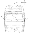
図3及び図4に示すように、ケース部5には、ユーザの背中と当接する背当面54が樹脂又はアルミ等の金属等により略四角形状に形成されており、背当面54には、左右方向に延びる複数の凹部55及び凸部56が交互に形成されている。従って、背負式電源1を背負った際には、ユーザの背中は、後述するパッド部61を介して凸部56と当接し、ユーザの背中(パッド部61)と凹部55との間には空間が存在することとなる。
As shown in FIGS. 3 and 4, the
上記したように、本実施の形態による電池パック51は、大容量を有しているため、背負式電源1の使用に伴い、電池パック51の温度が、ユーザが不快と感じる温度まで上昇する虞がある。しかしながら、本実施の形態による背負式電源1では、上記構成により、ユーザの背中と背当面54との間に通気性が確保されることとなるため、電池パック51において発生した熱のユーザの背中への伝達や、ユーザの背中での蒸れの発生が大幅に軽減されている。
As described above, since the
特に、本実施の形態では、図3及び図4に示すように、複数の凹部55及び凸部56は、左右(水平)方向に延びている。
In particular, in the present embodiment, as shown in FIGS. 3 and 4, the plurality of
このような構成により、左右方向に吹くことの多い風が、ユーザの背中と凹部55との間に形成され、左右方向に延びた空間を通過しやすくなるので、電池パック51において発生した熱のユーザの背中への伝達や、ユーザの背中での蒸れの発生が一層軽減されている。
With such a configuration, wind often blown in the left-right direction is formed between the user's back and the
更に、本実施の形態では、図5に示すように、ユーザの背中と当接する凸部56の内部は、電池パック51、制御基板52等が配置されていない空洞となっている。
Further, in the present embodiment, as shown in FIG. 5, the inside of the
このような構成により、ユーザの背中と電池パック51との間を断熱的に隔離することができるので、電池パック51において発生した熱のユーザの背中への伝達や、ユーザの背中での蒸れの発生が一層軽減されている。
With such a configuration, the user's back and the
また、図4に示すように、背当面54の下部には、ケーブル延出孔57が形成されており、ケーブル延出孔57からは、電動工具2(アダプタ3)と接続される電源ケーブル58が水平方向よりも上方向に延出している。
As shown in FIG. 4, a
このような構成により、ユーザが背負式電源1を背負った状態で地面等に座る際に、電源ケーブル58が地面等に当たって座る動作が妨げられることが防止されている。
With such a configuration, when the user sits on the ground or the like with the back-
更に、図3及び図4に示すように、背当面54には、ケーブル延出孔57から左右方向に延出するように形成されたガイド溝57aが形成されている。
Further, as shown in FIGS. 3 and 4, a
このような構成によれば、電源ケーブル58は、左右方向に延出するように形成されたガイド溝57aに沿って背当面54の左右いずれかの端部へ向けてガイドされることとなるため、ユーザの利き腕や電動工具2との関係に応じて、ユーザが所望の方向に電源ケーブル59を延出可能であり、作業性が向上する。また、電源ケーブル58の先端に接続された電動工具2による作業の際に電源ケーブル58が垂れ下がって作業効率が低下することも抑制されている。
According to such a configuration, the
図2(a)、図2(b)、及び、図5に示すように、背負部6は、パッド部61と、一対の肩ベルト62と、一対の腰ベルト63と、を備えている。
As shown in FIGS. 2A, 2B, and 5, the
パッド部61は、ユーザの背中と背当面54の間に配置されるものであり、背当面54と略同一サイズの非剛性部材により形成されている。
The
パッド部61には、図2(b)及び図5に示すように、クッション性を有する複数の当接部61aにより、複数の凹部(61b)が形成されている。このような構成により、ユーザの背中とパッド部61との間に通気性が確保されることとなるため、電池パック51において発生した熱のユーザの背中への伝達や、ユーザの背中での蒸れの発生が軽減されている。
As shown in FIGS. 2B and 5, the
パッド部61の左右方向の両端部には、図2(a)、図2(b)、及び、図5に示すように、ケース部5から延出した一対のトップストラップ61cが肩ベルト62に係合されている。ユーザは、トップストラップ61cの長さを調整することにより、ユーザの背中(パッド部61)とケース部5との間の隙間を調整することができ、また、ケース部5の荷重を肩ベルト62に効率的に分散させることができる。これにより、ケース部5をユーザの背中へフィットさせることが可能となる。また、ケース部の重心をユーザに近づけることが可能となるため、ユーザが背面方向へ転倒する虞を低減させることができる。更に、ケース部5の荷重が肩ベルト62に効率的に分散されることで、ユーザの疲労を大幅に減少させることが可能となる。
A pair of
一対の肩ベルト62は、パッド部61の両端部において、上部と下部に渡ってそれぞれ掛け渡されており、ユーザは、肩ベルト62によって形成された空間に肩を通すことにより、背負式電源1を背負うことが可能となる。
The pair of
また、パッド部61の両端部の下部からは、一対の腰ベルト63が略水平方向にそれぞれ延出している。一対の腰ベルト63の先端部は、互いに係合可能な構成となっており、先端部を係合させることにより、背負式電源1(背当面54)をユーザの体にフィットさせることが可能となっている。
A pair of
なお、水平方向において左右の肩ベルト62を係合可能とするための補助ベルトを腰ベルト63の上部に設けてもよく、このような構成により、使用時にユーザが体を動かした場合であっても、背負式電源1(背当面54)とユーザの体とのすれを低減させることが可能となる。
In addition, an auxiliary belt for enabling the left and
肩ベルト62及び腰ベルト63が接続されたパッド部61は、背当面54に形成された複数のネジ孔59(図4及び図5)に対してネジ留めされている。
The
本実施の形態による背負式電源1では、電池パック51は相当な重量となるため、ケース部5と背負部6との係合には、十分な注意が必要である。
In the backpack-
本実施の形態による背負式電源1では、パッド部61が背当面54に形成された複数のネジ孔59にネジ留めされているので、ケース部5と背負部6との接続が外れることが防止されている。また、上記トップストラップ61cを有する構造により、ケース部5と背負部6の係合に必要な力が分散されている。
In the backpack
また、複数のネジ孔59は、パッド部61(背当面54)の左右方向における両端部よりも中央側に形成されている。 Further, the plurality of screw holes 59 are formed at the center side with respect to both end portions in the left-right direction of the pad portion 61 (backing surface 54).
このような構成によれば、パッド部61の左右方向における両端部がケース部5に固定されていないため、非剛性部材により形成されたパッド部61が湾曲し、ユーザの体にフィットさせることが可能となっている。
According to such a configuration, since both end portions in the left-right direction of the
また、図2(a)及び図2(b)に示すように、ケース部5からは、制御基板52と接続された操作用ケーブル64が延出しており、操作用ケーブル64の先端には操作部65が接続されている。
As shown in FIGS. 2A and 2B, an
ここで、図2(a)及び図6(a)に示すように、各腰ベルト63には、ポケット(カバー部)63aが取り付けられており、ポケット63aと腰ベルト63との間には、操作部65及び操作用ケーブル64が挿通可能かつ操作用ケーブル64の余分な部分が収納可能な空間63bが形成されている。
Here, as shown in FIG. 2A and FIG. 6A, a pocket (cover) 63a is attached to each
このような構成によれば、背負式電源1による作業中に、操作用ケーブル64の余分な部分が枝等にひっかかる可能性や、操作用ケーブル64の余分な部分による作業効率の低下を抑制することが可能となる。また、ユーザの体格に関わらず操作用ケーブル64の余分な部分が生じなくなるので、ユーザの体格による背負式電源1の利便性の差異がなくなる。
According to such a configuration, it is possible to suppress a possibility that an extra portion of the
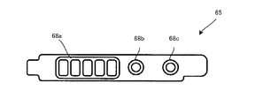
図6(b)に示すように、操作部65は、ボックス形状を有しており、その表面に、サブ電源スイッチ66、残量スイッチ67、残量表示LED68a、電源LED68b、及び、異常LED68cが、設けられている。
As shown in FIG. 6B, the
ユーザは、サブ電源スイッチ66をオフすることにより、背負式電源1から電動工具2への電力の供給を停止させることができ、また、残量スイッチ67を操作することにより、残量表示LED68aに電池パック51の残量を5段階で表示させることができる。
The user can stop the supply of electric power from the back load
このように、ケース部5から延出した腰ベルト63に操作部65が取り付けられていることにより、ユーザがケース5を背負った状態、すなわち、電動工具2で作業を行っている時等に電池パック51の残量等を確認することが容易となっている。
As described above, since the
また、図2(b)に示すように、腰ベルト63には、操作部65を収納するための収納部69が取り付けられている。
Further, as shown in FIG. 2B, a
腰ベルト63とポケット63aとの間に形成された空間63bを挿通するためには、操作部65は収納部69等に収納されていないシンプルな状態であることが好ましいが、その一方で、収納部69に収納されていない操作部65は、過度の衝撃や想定以上の浸水等に弱い。
In order to insert the
そこで、本実施の形態では、操作部65は、腰ベルト63とポケット63aとの間に形成された空間63bを挿通した上で収納部69に収納されており、このような構成により、操作部65の空間63bへの挿通を容易にしながらも、操作部65の破損やショート等をより抑制している。
Therefore, in the present embodiment, the
収納部69には、ユーザが、残量表示LED68a、電源LED68b、及び、異常LED68cを視認可能な透過部69aが形成されている。
The
このような構成により、残量表示LED等を腰ベルト63に保持した状態で、ユーザが残量表示LED68a等を視認することが可能となる。
With such a configuration, the user can visually recognize the remaining
更に、収納部69は、図6(c)に示すように、その上部を支点として回動可能な構成となっている。
Further, as shown in FIG. 6C, the
このような構成により、操作部65を腰ベルト63に保持した状態で、ユーザが残量表示LED68a等を視認することが可能となる。
With such a configuration, the user can visually recognize the remaining
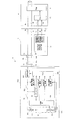
続いて、図7を用いて、ケース部5に収容された制御基板52の構成について説明する。図7に示すように、制御基板52を搭載した背負式電源1は、アダプタ3を介して充電器4と接続されることで、充電システムAを構成する。また、背負式電源1は、同一のアダプタ3を介して電動工具2と接続される構成となっている。
Next, the configuration of the
制御基板52は、電池側プラス端子5a及び電池側マイナス端子5b、を備えており、また、制御基板52には、上述したメイン電源スイッチ53と、レギュレータ521と、スイッチング素子522と、遮断回路523と、保護IC524と、サーミスタ525と、電池側マイコン526と、が搭載されている。
The
電池側プラス端子5a及び電池側マイナス端子5bは、電源ケーブル58と接続されており、また、電池側プラス端子5a及び電池側マイナス端子5bは、電池パック51のプラス端子51a及びマイナス端子51bとそれぞれ接続されている。電池パック51のプラス端子51aと電池側プラス端子5aとの間には、メイン電源スイッチ53、スイッチング素子522、及び、遮断回路523が、その順番で接続されている。
The battery side
レギュレータ521は、メイン電源スイッチ53とスイッチング素子522の間の接点に接続されており、電池パック51から出力された電圧を変圧し、駆動電圧として保護IC524及び電池側マイコン526に供給する。
The
スイッチング素子522は、FETから構成されている。上述したサブ電源スイッチ66は、電池側マイコン526と接続されており、サブ電源スイッチ66がオフされると、電池側マイコン526は、スイッチング素子522のゲートにオフ信号を出力してスイッチング素子522をオフさせる。
The switching
このような構成では、レギュレータ521は、スイッチング素子522よりも電池パック51側の電流路に接続されているので、電動工具2への電力供給を停止させるために主に使用されるサブ電源スイッチ66(スイッチング素子522)がオフされても、保護IC524及び電池側マイコン526へは、駆動電力が供給されることとなる。
In such a configuration, the
ところが、本実施の形態による背負式電源1は、所定のシーズンのみの使用が多い電動工具に好適なものであるところ、サブ電源スイッチ66(スイッチング素子522)のみがオフされた状態で放置されると、保護IC524及び電池側マイコン526へ電力が供給され続け、その結果、次のシーズンには、電池パック51の残容量が減少し、場合によっては、過放電等により電池パック51が劣化する虞がある。
However, the back-
そこで、本実施の形態による背負式電源1では、スイッチング素子522よりも電池パック51側の電流路上にメイン電源スイッチ53を設け、レギュレータ521は、メイン電源スイッチ53とスイッチング素子522の間の電流路に接続されている。
In view of this, in the backpack
このような構成により、背負式電源1を長時間使用しない場合にはメイン電源スイッチ53をオフしておくことで、保護IC524及び電池側マイコン526への電力供給も遮断することが可能となり、電力の浪費や過放電等による電池パック51の劣化を抑制することが可能な構成となっている。
With such a configuration, when the back-
また、本実施の形態では、メイン電源スイッチ53は、機械式スイッチから構成されているので、サブ電源スイッチ66に依らず全回路を停止させることが可能となる。
In the present embodiment, since the
なお、本実施の形態では、30Aもの電流を供給可能な大容量の電池パック51を採用しているため、メイン電源スイッチ53も、そのような大電流に耐久可能なものを採用している。
In this embodiment, since a large-
また、図3に示すように、本実施の形態による背負式電源1では、メイン電源スイッチ53は、ケース部5の側面に設けられている。メイン電源スイッチ53は、本実施の形態における側面のみならず、ケース部5の下面等、ユーザが背負った状態でも操作可能な位置に設けることが好適である。このような構成により、作業中に誤ってメイン電源スイッチ53がオフされてしまうことを抑制するのにならず、速やかに全回路を停止する必要が生じた時に、ユーザは、背負式電源1を背負ったままで、給電、及び、全回路を停止することが可能となる。
As shown in FIG. 3, the
遮断回路523は、FETから構成されており、電池側マイコン526による制御に基づき、電池側プラス端子5aと、電池パック51と、電池側マイナス端子5bとにより形成された電流路の解放・遮断を行う。
The
保護IC524は、充電時において電池パック51の満充電を検知した場合には、充電停止信号を電池側マイコン526に出力し、放電時において電池パック51の過放電又は過電流を検知した場合には、放電停止信号を電池側マイコン526に出力する。
The
サーミスタ525は、電池パック51の温度を電池温度信号として電池側マイコン526に出力する。
The
電池側マイコン526は、保護IC524から充電停止信号又は放電停止信号が入力された場合に、遮断回路523に電流路を遮断させる。
The battery-
また、電池パック51は、高温になると劣化が進行し、使用不能となる等の虞があるので、電池側マイコン526は、サーミスタ525から入力された電池温度信号が所定以上の温度を示すものである場合にも、遮断回路523に電流路を遮断させる。
In addition, since the
また、充電時においては、電池パック51の規格に適合していない充電器4が背負式電源1に接続されることにより、電池パックの51の規格よりも大きな電圧又は電流が充電器4から電池パック51に供給されたような場合にも、電池パック51が使用不能となる虞がある。
In addition, when charging, the
従って、電池側マイコン526は、電池パック51に供給される電圧及び電流を検出し(電圧・電流検出信号)、電池パック51に供給される電圧又は電流が所定以上であった場合にも、遮断回路523に電流路を遮断させる。
Accordingly, the battery-
このように、本実施の形態による背負式電源1では、電池パック51が、満充電や異常を検知した場合に、電池パック51側で電流路を遮断する。従って、背負式電源1に接続された充電器4に依存せずに、背負式電源1本体内で独立して満充電時や異常時に電池パック51への電力の供給を確実に停止させることができるので、電池パック51の劣化等を抑制し、使用不能となる可能性を低減させている。
Thus, in the backpack
続いて、充電器4の構成について説明する。
Next, the configuration of the
充電器4は、充電器側プラス端子4aと、充電器側マイナス端子4bと、電池種入力端子4cと、電池温度入力端子4dと、電源41と、充電器側マイコン42と、を備えた従来の充電器である。
The
電源41は、商用電源からの交流電力を直流電力に変換して充電器側プラス端子4a及び充電器側マイナス端子4bから充電電力として出力する。
The
充電器側マイコン42は、電池種入力端子4cに入力された電池種信号及び電池温度入力端子4dに入力された電池温度信号に基づき、電源41が出力する充電電圧及び充電電流を制御する。但し、充電器側マイコン42は、電池種入力端子4c及び電池温度入力端子4dに所定範囲に含まれる信号が入力されていない場合には、充電動作を行わないよう、すなわち、充電器側プラス端子4aと充電器側マイナス端子4bとの間に電圧を印加しないよう電源41を制御する。
The
続いて、アダプタ3の構成について説明する。
Next, the configuration of the
背負式電源1は、電動工具2又は充電器4には、電源ケーブル58と接続されたアダプタ3を介して接続される。
The back-
なお、図7及び図8に示すように、電源ケーブル58は、両端に設けられたコネクタ58a及び58bを介して、螺合により背負式電源1及びアダプタ3と着脱可能に接続されている。
As shown in FIGS. 7 and 8, the
このような構成によれば、作業中に誤って電源ケーブル58を切断してしまったような場合であっても、電源ケーブル58を容易に交換して作業を再開することが可能となる。また、電源ケーブル58を電動工具2の定格出力に応じた太さのものに交換することが可能となるので、例えば、低出力の電動工具2に接続される場合には、細めの電源ケーブル58に交換することで、作業効率を大幅に向上させることが可能となる。
According to such a configuration, even if the
また、電源ケーブル58は、図8に示すように、螺合により互いに接続されるコネクタ58c及び58dを備えており、それらの接続を解除することにより、電源ケーブル58を背負式電源1側とアダプタ3側とに分離することが可能な構成となっている。
Further, as shown in FIG. 8, the
このような構成によれば、アダプタ3を背負式電源1から容易に分離することが可能となるので、例えば、休憩時等に余計な重量がユーザにかかることが防止される。
According to such a configuration, the
図8及び図9に示すように、アダプタ3は、上面に電動工具2と接続される横スライドタイプの接続部31を備えており、また、電源ケーブル58は、下面から下方向に延出するように接続されている。
As shown in FIGS. 8 and 9, the
このような構成によれば、電源ケーブル58からの力がアダプタ3へかかる方向(図8及び図9では上下方向)と、アダプタ3と電動工具2との係合を解除する方向(図8及び図9では左右方向)と、が異なっているので、作業中にアダプタ3と電動工具2との係合が解除されることが抑制されている。
According to such a configuration, the direction in which the force from the
特に、本実施の形態では、電源ケーブル58からの力がアダプタ3へかかる方向(図8及び図9では上下方向)と、アダプタ3と電動工具2との係合を解除する方向(図8及び図9では左右方向)とが、直交する関係となっている。
In particular, in the present embodiment, the direction in which the force from the
このような構成によれば、電源ケーブル58からアダプタ3にかかる上下方向の力が、アダプタ3と電動工具2との係合を解除する左右方向の力に対して摩擦力として機能するので、アダプタ3と電動工具2との係合が解除されることが効果的に抑制されている。
According to such a configuration, the vertical force applied from the
図7に戻り、アダプタ3の回路構成について説明する。
Returning to FIG. 7, the circuit configuration of the
アダプタ3は、第1アダプタ側プラス端子3aと、第1アダプタ側マイナス端子3bと、第2アダプタ側プラス端子3cと、第2アダプタ側マイナス端子3dと、疑似電池種出力端子3eと、疑似電池温度出力端子3fと、放電停止信号出力端子3gと、疑似信号出力手段32と、を備えている。
The
第1アダプタ側プラス端子3a及び第1アダプタ側マイナス端子3bは、充電器側プラス端子4a及び充電器側マイナス端子4bと、それぞれ接続可能な構成となっている。 The first adapter side plus terminal 3a and the first adapter side minus terminal 3b are configured to be connectable to the charger side plus terminal 4a and the charger side minus terminal 4b, respectively.
また、第2アダプタ側プラス端子3c及び第2アダプタ側マイナス端子3dは、電源ケーブル58を介して、電池側プラス端子5a及び電池側マイナス端子5bと、それぞれ接続されている。
The second adapter side
また、疑似電池種出力端子3e及び疑似電池温度出力端子3fは、電池種入力端子4c及び電池温度入力端子4dと、それぞれ接続可能な構成となっている。
Moreover, the pseudo battery
放電停止信号出力端子3gは、電動工具2の放電停止信号入力端子と接続可能な構成となっている。
The discharge stop
疑似信号出力手段32は、疑似電池種出力端子3e及び疑似電池温度出力端子3fを介して前記所定範囲に含まれる疑似信号を出力する。
The pseudo signal output means 32 outputs a pseudo signal included in the predetermined range via the pseudo battery
ここで、本実施の形態による背負式電源1は、大容量の電池パック51により大電流を供給可能な構成であるが、大電流を供給するためには、太い電源ケーブル58が必要となってくる。その一方で、太い電源ケーブル58は、電動工具2による作業効率を低下させる虞があるので、電源ケーブル58はスリムであることが望ましい。
Here, the back-
そこで、本実施の形態では、背負式電源1に電池種出力端子、電池温度出力端子、放電停止信号出力端子を用いず、電源ケーブル58が、それらの端子に対応した信号線を備えないことにより、大電流を供給可能でありながらスリムな電源ケーブル58を実現している。
Therefore, in the present embodiment, the battery type output terminal, the battery temperature output terminal, and the discharge stop signal output terminal are not used for the backpack
但し、このような構成の背負式電源1では、電池種信号及び電池温度信号を出力することができないので、このような信号に基づいて給電を開始する構成の充電器4では、充電動作を行わせることができない。
However, since the back-
そこで、本実施の形態では、背負式電源1と充電器4との間にアダプタ3を接続し、アダプタ3の疑似信号出力手段32から前記所定範囲に含まれる疑似信号を出力することにより充電器4に充電動作を行わせている。
Therefore, in the present embodiment, the
その一方で、アダプタ3の疑似信号出力手段32から出力される疑似信号は、電池パック51の満充電や異常時にも変化しないため、このような構成では充電器4側で充電動作を停止させることができない。
On the other hand, since the pseudo signal output from the pseudo signal output means 32 of the
そこで、本実施の形態では、満充電等を検知した場合には、遮断回路523により電流路を遮断し、背負式電源1本体に設けられた電池パック51への充電を停止させている。
Therefore, in the present embodiment, when full charge or the like is detected, the current path is interrupted by the interrupting
これにより、大電流を供給しながらもスリムな電源ケーブル58を実現すると同時に、電池パック51の満充電や異常時に、電池パック51への充電を適切に停止させることが可能となる。
As a result, a
なお、電動工具2は、放電遮断回路を備え、電池パック51の過放電又は過電流を検知した場合には、放電遮断回路に電流路を遮断させる従来の構成を有している。また、本構成のアダプタ3は、搭載されたマイコンにより電圧や電流を検知しているため、アダプタ3が過電流や過度の電圧低下等の異常を検知した場合には、前記電動工具2の放電遮断回路に対し、電流路を遮断する信号を送出することができる。
In addition, the
このように、本実施の形態による背負式電源1では、過放電又は過電流が生じた場合には、背負式電源1側及び電動工具2側の双方で電流路を遮断させるので、電池パック51の劣化や使用不能となる可能性をより適切に抑制することが可能となる。
As described above, in the back load
次に、図10を用いて、本発明の第2の実施の形態について説明する。 Next, a second embodiment of the present invention will be described with reference to FIG.
本実施の形態では、充電器4の充電器側マイコン42は、充電開始からの時間をカウントするタイマ機能を有しており、カウントが所定時間を超えた場合に満充電と判断して電源41の充電動作を停止させるような制御を行っている。
In the present embodiment, the charger-
しかしながら、このような構成では、所定時間よりも長い充電時間を必要とする電池パック51が充電器4に接続された場合には、電池パック51を満充電にすることができない。
However, in such a configuration, when the
そこで、本実施の形態では、アダプタ3に、充電器リセット手段33を設け、充電開始から所定時間を超える前に、充電器リセット手段33から充電器4の充電器側マイコン42にタイマリセット信号を出力してカウントをリセットし、充電を継続させる。
Therefore, in the present embodiment, the
このような構成により、所定時間よりも長い充電時間を必要とする電池パック51がタイマ機能を有する充電器4に接続された場合であっても、満充電となる前に電池パック51への充電が終了してしまうことを防止することが可能となる。
With such a configuration, even when the
但し、この場合、充電器4側では、満充電を判断することができなくなるので、電池パック51を過充電になるまで充電してしまう虞がある。しかしながら、上述したように、本実施の形態による背負式電源1は、自ら電池パック51の満充電を判断して電流路を遮断することができる。このような構成により、電池パック51が過充電になることを防止しながらも、様々な容量を有する電池パック51を満充電まで充電することが可能となる。
However, in this case, since the
本発明による電動工具は、上述した実施の形態に限定されず、特許請求の範囲に記載された範囲で種々の改良や変形が可能である。 The power tool according to the present invention is not limited to the above-described embodiment, and various improvements and modifications can be made within the scope described in the claims.
例えば、図11に示すように、背負式電源1に対してアダプタ3を装着(収納)可能な構成とし、背負式電源1にアダプタ3が装着されると、メイン電源スイッチ53がオフされるようにしてもよい。
For example, as shown in FIG. 11, the
このような構成によれば、作業終了時にメイン電源スイッチ53を切り忘れることが防止されるので、電池パック51が過放電となることが抑制される。
According to such a configuration, it is possible to prevent the
また、同様の目的から、電源ケーブル58のコネクタ58a背負式電源1から取り外されると、メイン電源スイッチ53がオフされるようにしてもよい。
For the same purpose, the
また、図12(a)及び図12(b)に示すように、電動工具2と接続されていない場合にアダプタ3がユーザの動作を妨げることを防止するために、腰ベルト63にアダプタ3と係合可能なアダプタ収納部材34を設けてもよい。なお、図12(a)及び図12(b)では、腰ベルト63がアダプタ収納部材34の挿通孔34aを挿通するような構成となっているが、単に腰ベルト63と引っかかるような構成であってもよい。
In addition, as shown in FIGS. 12A and 12B, the
また、図12に示すように、電源ケーブル58を巻きつけるための巻回部34bを更にアダプタ3に設けることで、余分な電源ケーブル58がユーザの動作を妨げることを防止することも可能となる。
Further, as shown in FIG. 12, by providing the
また、図13(a)及び図13(b)に示すように、アダプタ3を収容可能な収容部36を、係合部63cを介して腰ベルト63に取り付けてもよい。なお、図13の(a)は、収容部36の側面図、図13の(b)は、収容部36の平面図である。
Further, as shown in FIGS. 13A and 13B, the
また、図14(a)及び図14(b)に示すように、アダプタ3を収容可能な収容部37をケース部5の下端又はその近傍の背負部6に取り付けてもよい。
Further, as shown in FIGS. 14A and 14B, an
なお、図14(a)及び図14(b)に示す収容部37は、布等を円筒形状に巻いたものであり、その左右方向における両端部に閉鎖紐37aが取り付けられている。ユーザは、閉鎖紐37aを絞ることにより、収容部37の解放端を閉鎖することが可能な構成となっている。
In addition, the
背負式電源1を背負った状態では、ユーザは、ケース部5に係合された収容部37にアダプタ3を収容する動作を後ろ手で行うこととなるが、上記構成によれば、アダプタ3を容易に収容部37に収容することが可能となる。
In a state where the backpack
また、図15に示すように、残量表示LED68a、電源LED68b、及び、異常LED68cを操作部65の上面に設けてもよい。
Further, as shown in FIG. 15, a remaining
このような構成によれば、操作部65を傾けることなく、ユーザが電池パック51の残量等を確認することが可能となる。
According to such a configuration, the user can check the remaining amount of the
また、上記実施の形態によるアダプタ3は、背負式電源1から出力された電圧をそのまま電動工具2へ出力したが、様々な定格電圧を有する電動工具2に対応するためにアダプタ3内で変圧を行ってもよい。この場合、電源ケーブル58を電動工具2の定格出力に応じた太さのものに交換することが可能となるので、例えば、低出力の電動工具2に接続される場合には、細めの電源ケーブル58に交換することで、作業効率を向上させることが可能となる。
Moreover, although the
また、同様の目的から、背負式電源1に電圧変換回路を備えてもよい。その場合には、電圧変換回路は、不使用時の電力の浪費を防止するために、メイン電源スイッチ53よりも電池側プラス端子5aに接続されていることが好ましい。
For the same purpose, the back-
また、上記実施の形態では、操作部65は、フラットケーブル64により電池側マイコン526との通信を行ったが、カールコードや無線により通信を行ってもよい。
In the above-described embodiment, the
また、上記実施の形態では、操作部65は、面ファスナーにより一方の腰ベルト63に着脱可能に取り付けられていたが、透明ポケット、フック、クリップ等により取り付けられてもよく、また、肩ベルト64に取り付けられてもよい。
In the above embodiment, the
また、第2の実施の形態において、充電器側マイコン42は、リセット信号が入力された場合に充電動作を停止させるタイプと、信号が遮断された場合にリセット信号が入力されたものと判断して充電動作を停止させるタイプの双方が考えられるので、アダプタ3の充電器リセット手段33は、充電器側マイコン42のタイプに応じて信号を出力又は遮断すればよい。
In the second embodiment, the charger-
また、パッド部61と背当面54との間にずれが生じることを抑制するために、パッド部61の背当面54と対向する面には、背当面54に形成された水平方向に延びる凹部55及び凸部56と直交する上下方向に延びる複数の溝が形成されていてもよい。
In addition, in order to suppress the occurrence of displacement between the
また、第1の実施の形態では、電池パック51満充電又は異常を検知した場合に遮断回路523により電流路を遮断したが、電池パック51満充電及び異常の少なくとも一方を検知した場合に遮断してもよい。
Further, in the first embodiment, when the
1 背負式電源
2 電動工具
3 アダプタ
4 充電器
5 ケース部
6 背負部
DESCRIPTION OF
Claims (4)
前記ケース部を背負うための背負部と、
前記ケース部から延出したケーブルと、
前記背負部上に形成されたカバー部と、
を備え、
前記ケーブルは、前記背負部と前記カバー部との間に形成された空間を挿通しており、前記空間には、前記ケーブルの余分な部分を収納可能であることを特徴とする背負式電源。 A case portion containing a battery pack;
A backpack for carrying the case part on the back;
A cable extending from the case portion;
A cover portion formed on the backpack;
With
The cable is inserted through a space formed between the backpack and the cover, and an extra portion of the cable can be stored in the space.
前記背負部に係合可能かつ前記残量表示部を収納可能な収納部と、
を更に備え、
前記残量表示部は、前記空間を前記ケーブルと共に挿通した上で前記収納部に収容されていることを特徴とする請求項1に記載の背負式電源。 A remaining amount display portion provided at the tip of the cable for displaying the remaining amount of the battery pack;
A storage portion that can be engaged with the backpack and can store the remaining amount display portion;
Further comprising
The backpack type power supply according to claim 1, wherein the remaining amount display unit is housed in the housing unit after being inserted through the space together with the cable.
前記ケース部を背負うための背負部と、
前記ケース部から延出したケーブルと、
前記電池パックの残量を表示するために前記ケーブルの先端に設けられた残量表示部と、
前記背負部に係合可能かつ前記残量表示部を収納可能な収納部と、
を備え、
前記収納部は、前記残量表示部を視認可能な透過部を有していることを特徴とする背負い式電源。 A case portion containing a battery pack;
A backpack for carrying the case part on the back;
A cable extending from the case portion;
A remaining amount display portion provided at the tip of the cable for displaying the remaining amount of the battery pack;
A storage portion that can be engaged with the backpack and can store the remaining amount display portion;
With
The backpack type power supply characterized by the said accommodating part having the permeation | transmission part which can visually recognize the said remaining amount display part.
前記ケース部を背負うための背負部と、
前記ケース部から延出したケーブルと、
前記電池パックの残量を表示するために前記ケーブルの先端に設けられ、前記背負部に係合された残量表示部と、
を備え、
前記残量部は、前記ケース部が背負われた状態において、ユーザが上方から視認可能なように回動可能であることを特徴とする背負式電源。 A case portion containing a battery pack;
A backpack for carrying the case part on the back;
A cable extending from the case portion;
A remaining amount display portion provided at the end of the cable for displaying the remaining amount of the battery pack and engaged with the backpack;
With
The backside power supply, wherein the remaining amount portion is rotatable so that a user can visually recognize the case from above when the case portion is carried on the back.
Priority Applications (5)
| Application Number | Priority Date | Filing Date | Title |
|---|---|---|---|
| JP2012153128A JP5958750B2 (en) | 2012-07-06 | 2012-07-06 | Back load type power supply |
| US13/935,347 US9391305B2 (en) | 2012-07-06 | 2013-07-03 | Backpack-type power supply including operation portion |
| DE202013102928U DE202013102928U1 (en) | 2012-07-06 | 2013-07-04 | A backpack-type power supply comprising an operating section |
| FR1356630A FR2992836B1 (en) | 2012-07-06 | 2013-07-05 | BACKPACK-TYPE FEEDING COMPRISING AN ACTUATION PART |
| CN201320400281.0U CN203398823U (en) | 2012-07-06 | 2013-07-05 | Back pack type power supply |
Applications Claiming Priority (1)
| Application Number | Priority Date | Filing Date | Title |
|---|---|---|---|
| JP2012153128A JP5958750B2 (en) | 2012-07-06 | 2012-07-06 | Back load type power supply |
Publications (2)
| Publication Number | Publication Date |
|---|---|
| JP2014017099A true JP2014017099A (en) | 2014-01-30 |
| JP5958750B2 JP5958750B2 (en) | 2016-08-02 |
Family
ID=50111631
Family Applications (1)
| Application Number | Title | Priority Date | Filing Date |
|---|---|---|---|
| JP2012153128A Active JP5958750B2 (en) | 2012-07-06 | 2012-07-06 | Back load type power supply |
Country Status (1)
| Country | Link |
|---|---|
| JP (1) | JP5958750B2 (en) |
Cited By (4)
| Publication number | Priority date | Publication date | Assignee | Title |
|---|---|---|---|---|
| WO2016189798A1 (en) * | 2015-05-28 | 2016-12-01 | パナソニックIpマネジメント株式会社 | Electrical stimulation device |
| FR3056020A1 (en) * | 2016-09-13 | 2018-03-16 | Pellenc | ELECTRIC BATTERY DEVICE FOR BATTERY SUPPORT |
| US10749430B2 (en) | 2015-03-13 | 2020-08-18 | Positec Power Tools (Suzhou) Co., Ltd. | Power transmission apparatus and control method therefor, and power supply system |
| WO2021111849A1 (en) * | 2019-12-06 | 2021-06-10 | 工機ホールディングス株式会社 | Battery pack and electrical apparatus system |
Citations (5)
| Publication number | Priority date | Publication date | Assignee | Title |
|---|---|---|---|---|
| JPH01166901U (en) * | 1988-05-16 | 1989-11-22 | ||
| JP2000164182A (en) * | 1998-11-27 | 2000-06-16 | Makita Corp | Battery pack |
| JP2011055680A (en) * | 2009-09-04 | 2011-03-17 | Makita Corp | Battery pack |
| JP2011216304A (en) * | 2010-03-31 | 2011-10-27 | Makita Corp | Portable power source bag |
| WO2013008506A1 (en) * | 2011-07-14 | 2013-01-17 | 株式会社 マキタ | Portable power-source bag |
-
2012
- 2012-07-06 JP JP2012153128A patent/JP5958750B2/en active Active
Patent Citations (5)
| Publication number | Priority date | Publication date | Assignee | Title |
|---|---|---|---|---|
| JPH01166901U (en) * | 1988-05-16 | 1989-11-22 | ||
| JP2000164182A (en) * | 1998-11-27 | 2000-06-16 | Makita Corp | Battery pack |
| JP2011055680A (en) * | 2009-09-04 | 2011-03-17 | Makita Corp | Battery pack |
| JP2011216304A (en) * | 2010-03-31 | 2011-10-27 | Makita Corp | Portable power source bag |
| WO2013008506A1 (en) * | 2011-07-14 | 2013-01-17 | 株式会社 マキタ | Portable power-source bag |
Cited By (11)
| Publication number | Priority date | Publication date | Assignee | Title |
|---|---|---|---|---|
| US10749430B2 (en) | 2015-03-13 | 2020-08-18 | Positec Power Tools (Suzhou) Co., Ltd. | Power transmission apparatus and control method therefor, and power supply system |
| US11601002B2 (en) | 2015-03-13 | 2023-03-07 | Positec Power Tools (Suzhou) Co., Ltd. | Electrical energy transmission apparatus, method for controlling same, and power supply system |
| WO2016189798A1 (en) * | 2015-05-28 | 2016-12-01 | パナソニックIpマネジメント株式会社 | Electrical stimulation device |
| JP2016220848A (en) * | 2015-05-28 | 2016-12-28 | パナソニックIpマネジメント株式会社 | Electrostimulator |
| TWI704936B (en) * | 2015-05-28 | 2020-09-21 | 日商松下知識產權經營股份有限公司 | Electrical stimulation device |
| FR3056020A1 (en) * | 2016-09-13 | 2018-03-16 | Pellenc | ELECTRIC BATTERY DEVICE FOR BATTERY SUPPORT |
| WO2018050981A1 (en) * | 2016-09-13 | 2018-03-22 | PELLENC (Société Anonyme) | Electric battery device, for battery support |
| CN109792011A (en) * | 2016-09-13 | 2019-05-21 | 佩朗股份有限公司 | Cell apparatus for battery support |
| US10916743B2 (en) | 2016-09-13 | 2021-02-09 | Pellenc | Electric battery device, for battery support |
| WO2021111849A1 (en) * | 2019-12-06 | 2021-06-10 | 工機ホールディングス株式会社 | Battery pack and electrical apparatus system |
| JP7424392B2 (en) | 2019-12-06 | 2024-01-30 | 工機ホールディングス株式会社 | Battery packs and electrical equipment systems |
Also Published As
| Publication number | Publication date |
|---|---|
| JP5958750B2 (en) | 2016-08-02 |
Similar Documents
| Publication | Publication Date | Title |
|---|---|---|
| JP6124046B2 (en) | Back load type power supply | |
| JP2014017952A (en) | Backpack power supply | |
| EP2869970B1 (en) | Backpack-type power supply | |
| US9391305B2 (en) | Backpack-type power supply including operation portion | |
| JP6296132B2 (en) | Back load type power supply | |
| US5929597A (en) | Portable electrical power system to supply direct current voltage | |
| US20120048588A1 (en) | Battery devices for power tools | |
| US20090072784A1 (en) | Inductive charger battery replacement system, device & method | |
| JP5958750B2 (en) | Back load type power supply | |
| AU2014100127A4 (en) | Mobile electric device with at least two lithium-ion batteries and arrangement of two such batteries electrically connected in series | |
| JP6108149B2 (en) | Battery pack, adapter capable of connecting charger and battery pack, and charging system including them | |
| JP2014017954A (en) | Power supply device | |
| ES2890273T3 (en) | protective helmet | |
| JP6016012B2 (en) | Back load type power supply | |
| JP2014017951A (en) | Adapter | |
| JP2014014891A (en) | Adapter | |
| JP2014014890A (en) | Adapter | |
| JP5975277B2 (en) | Back load type power supply |
Legal Events
| Date | Code | Title | Description |
|---|---|---|---|
| A621 | Written request for application examination |
Free format text: JAPANESE INTERMEDIATE CODE: A621 Effective date: 20141226 |
|
| A977 | Report on retrieval |
Free format text: JAPANESE INTERMEDIATE CODE: A971007 Effective date: 20151007 |
|
| A131 | Notification of reasons for refusal |
Free format text: JAPANESE INTERMEDIATE CODE: A131 Effective date: 20151008 |
|
| A521 | Request for written amendment filed |
Free format text: JAPANESE INTERMEDIATE CODE: A523 Effective date: 20151203 |
|
| A131 | Notification of reasons for refusal |
Free format text: JAPANESE INTERMEDIATE CODE: A131 Effective date: 20151224 |
|
| A521 | Request for written amendment filed |
Free format text: JAPANESE INTERMEDIATE CODE: A523 Effective date: 20160218 |
|
| A131 | Notification of reasons for refusal |
Free format text: JAPANESE INTERMEDIATE CODE: A131 Effective date: 20160307 |
|
| A521 | Request for written amendment filed |
Free format text: JAPANESE INTERMEDIATE CODE: A523 Effective date: 20160427 |
|
| TRDD | Decision of grant or rejection written | ||
| A01 | Written decision to grant a patent or to grant a registration (utility model) |
Free format text: JAPANESE INTERMEDIATE CODE: A01 Effective date: 20160526 |
|
| A61 | First payment of annual fees (during grant procedure) |
Free format text: JAPANESE INTERMEDIATE CODE: A61 Effective date: 20160608 |
|
| R150 | Certificate of patent or registration of utility model |
Ref document number: 5958750 Country of ref document: JP Free format text: JAPANESE INTERMEDIATE CODE: R150 |
|
| S533 | Written request for registration of change of name |
Free format text: JAPANESE INTERMEDIATE CODE: R313533 |
|
| R350 | Written notification of registration of transfer |
Free format text: JAPANESE INTERMEDIATE CODE: R350 |