JP2014014221A - Slip suppression drive control device and slip suppression method for electric vehicle - Google Patents
Slip suppression drive control device and slip suppression method for electric vehicle Download PDFInfo
- Publication number
- JP2014014221A JP2014014221A JP2012150359A JP2012150359A JP2014014221A JP 2014014221 A JP2014014221 A JP 2014014221A JP 2012150359 A JP2012150359 A JP 2012150359A JP 2012150359 A JP2012150359 A JP 2012150359A JP 2014014221 A JP2014014221 A JP 2014014221A
- Authority
- JP
- Japan
- Prior art keywords
- torque
- slip
- value
- angular acceleration
- threshold
- Prior art date
- Legal status (The legal status is an assumption and is not a legal conclusion. Google has not performed a legal analysis and makes no representation as to the accuracy of the status listed.)
- Pending
Links
Images


Classifications
-
- Y—GENERAL TAGGING OF NEW TECHNOLOGICAL DEVELOPMENTS; GENERAL TAGGING OF CROSS-SECTIONAL TECHNOLOGIES SPANNING OVER SEVERAL SECTIONS OF THE IPC; TECHNICAL SUBJECTS COVERED BY FORMER USPC CROSS-REFERENCE ART COLLECTIONS [XRACs] AND DIGESTS
- Y02—TECHNOLOGIES OR APPLICATIONS FOR MITIGATION OR ADAPTATION AGAINST CLIMATE CHANGE
- Y02T—CLIMATE CHANGE MITIGATION TECHNOLOGIES RELATED TO TRANSPORTATION
- Y02T10/00—Road transport of goods or passengers
- Y02T10/60—Other road transportation technologies with climate change mitigation effect
- Y02T10/72—Electric energy management in electromobility
Abstract
Description
本発明は、電気車両の駆動輪のスリップを抑制する制御装置及びスリップ抑制方法に関する。 The present invention relates to a control device and a slip suppression method for suppressing slip of a drive wheel of an electric vehicle.
車両の駆動輪がスリップしたことを検出して、その車両に搭載される電動機から駆動輪に伝わるトルクを制限する制御装置がある(例えば、特許文献1参照)。このような制御装置では、例えば、駆動輪の角加速度が閾値以上になりスリップ状態であることを判断すると、トルクを制限し、そのトルク制限に伴って駆動輪が路面にグリップし始めて駆動輪の角加速度が低下しスリップ状態でなくなったことを判断すると、トルクの制限を解除する。 There is a control device that detects that a drive wheel of a vehicle has slipped and limits torque transmitted from an electric motor mounted on the vehicle to the drive wheel (see, for example, Patent Document 1). In such a control device, for example, when it is determined that the angular acceleration of the driving wheel is equal to or greater than the threshold value and the slip state is detected, the torque is limited, and the driving wheel starts to grip the road surface with the torque limitation. When it is determined that the angular acceleration has dropped and the slip state has been lost, the torque limit is released.
しかしながら、上述の制御装置において、スリップ状態の判断精度を上げるために、例えば、スリップ状態判断用の閾値を小さくすることが考えられるが、スリップ状態判断用の閾値を小さくしてしまうと、滑り難い路面を車両が走行中であるにもかかわらず、頻繁にスリップ状態であることが判断されてしまうおそれがある。そして、そのような路面を車両が走行中に、何度もスリップ状態であることが判断されて、その度にトルクが制限されると、スムーズな走行の妨げになってしまう。 However, in the above-described control device, in order to increase the determination accuracy of the slip state, for example, it is conceivable to reduce the slip condition determination threshold. However, if the slip state determination threshold is decreased, it is difficult to slip. Although the vehicle is traveling on the road surface, it may be frequently determined that the vehicle is slipping. Then, if it is determined that the vehicle is slipping many times while the vehicle is traveling on such a road surface and the torque is limited each time, smooth travel is hindered.
そこで、本発明では、車両の駆動輪のスリップ状態を精度良く判断しつつ、スリップ状態判断時の電動機のトルク制限によるスムーズな走行の妨げを抑えることが可能な電気車両のスリップ抑制駆動制御装置及びスリップ抑制方法を提供することを目的とする。 Therefore, in the present invention, a slip suppression drive control device for an electric vehicle capable of accurately determining the slip state of the drive wheel of the vehicle and suppressing a hindrance to smooth travel due to torque limitation of the electric motor at the time of slip state determination, and An object is to provide a slip suppression method.
本発明の電気車両のスリップ抑制駆動制御装置は、車両に搭載される電動機のトルクにより駆動する駆動輪の角加速度を取得する角加速度取得手段と、前記角加速度取得手段により取得される角加速度に対応するカウンタ値の積算値が第1の閾値以上になると、前記駆動輪がスリップ状態であると判断するスリップ判断手段と、前記スリップ判断手段により前記駆動輪がスリップ状態であると判断されると、前記電動機のトルクを制限させるトルク制限手段とを備える。 The slip suppression drive control device for an electric vehicle according to the present invention includes an angular acceleration acquisition unit that acquires angular acceleration of a drive wheel that is driven by torque of an electric motor mounted on the vehicle, and an angular acceleration that is acquired by the angular acceleration acquisition unit. When the integrated value of the corresponding counter value is equal to or greater than a first threshold value, slip determination means for determining that the drive wheel is in a slip state, and when the drive wheel is determined to be in a slip state by the slip determination means. And torque limiting means for limiting the torque of the electric motor.
例えば、スリップし始めてから完全にスリップ状態になった直後の駆動輪の角加速度に対応するカウンタ値を第1の閾値とすることで、駆動輪がスリップ状態であることを精度良く判断することができる。また、例えば、第1の閾値をカウンタ値の最大値よりも大きくすることで、積算値を少なくとも2回求めないと駆動輪がスリップ状態であるか否かを判断することができないようにすることができる。そのため、スリップ状態であることが判断される頻度を低減することができ、スリップ状態であることが頻繁に判断される際のトルク制限によるスムーズな走行の妨げを抑えることができる。 For example, it is possible to accurately determine that the driving wheel is in the slip state by setting the counter value corresponding to the angular acceleration of the driving wheel immediately after the slip is started and immediately after the slip is started as the first threshold value. it can. Further, for example, by making the first threshold value larger than the maximum value of the counter value, it is possible to determine whether or not the driving wheel is in a slip state unless the integrated value is obtained at least twice. Can do. Therefore, it is possible to reduce the frequency at which it is determined that the vehicle is in the slip state, and it is possible to suppress a hindrance to smooth travel due to torque limitation when it is frequently determined that the vehicle is in the slip state.
本発明は、電動機で走行する車両において、駆動輪のスリップ状態を精度良く判断しつつ、スリップ状態判断時の電動機のトルク制限によるスムーズな走行の妨げを抑えることができる。 According to the present invention, in a vehicle that runs on an electric motor, it is possible to accurately determine the slip state of the drive wheel and to suppress the hindrance to smooth running due to the torque limit of the electric motor when the slip state is determined.
図1は、本発明の実施形態の制御装置を備える車両の一例を示す図である。 Drawing 1 is a figure showing an example of vehicles provided with a control device of an embodiment of the present invention.
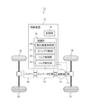
図1に示す車両11は、例えば、電気自動車や電動フォークリフトなどであって、バッテリ12と、インバータ回路13と、電動機14と、制御装置15と、4つの駆動輪16と、回転数検出部17とを備える。
A vehicle 11 illustrated in FIG. 1 is, for example, an electric vehicle or an electric forklift, and includes a
制御装置15は、制御部18と、記憶部19とを備える。
The
制御部18は、角加速度取得部20(角加速度取得手段)と、スリップ判断部21(スリップ判断手段)と、トルク制限部22(トルク制御手段)と、トルク取得部23(トルク取得手段)とを備える。
The
バッテリ12は、例えば、リチウムイオンバッテリや鉛蓄電池などにより構成され、インバータ回路13に直流の電力を供給する。
The
インバータ回路13は、制御部18による動作制御に基づいて、バッテリ12から供給される直流の電力を、例えば、3相の交流電力に変換して出力する。
The
電動機14は、例えば、3相モータであって、インバータ回路13から出力される3相の交流電力により駆動する。電動機14が駆動すると、電動機14のトルクが駆動輪16に伝わり駆動輪16が回転して車両11が走行する。
The
回転数検出部17は、例えば、レゾルバなどにより構成され、電動機14の回転数(回転量)を検出する。また電動機14のロータの位相を検出することも可能である。
The rotation
制御部18は、例えば、CPU(Central Processing Unit)又はプログラマブルなデバイス(FPGA(Field Programmable Gate Array)やPLD(Programmable Logic Device))などにより構成され、記憶部19に記憶されているプログラムを実行することにより、角加速度取得部20、スリップ判断部21、トルク制限部22、及びトルク取得部23などを機能させてインバータ回路13の動作制御を行う。なお、例えば、車両11の運転者によりイグニッションボタンが押されるなどして電動機14の駆動開始指示が制御部18に入力されると、制御部18によりインバータ回路13の動作制御が開始されるものとする。また、例えば、制御部18は、車両11の走行中、アクセルペダルの位置を検出するセンサの出力やブレーキペダルの位置を検出するセンサの出力などに基づいて、電動機14の目標トルクや回転数を取得し、その取得した値を目標電流値に変換する。回転数検出部17や図示しない電流センサ等の値をフィードバックし、目標電流値になるように、出力電流・出力電圧を決定してインバータ回路13の動作制御を行うものとする。また、後述するとおり、制御部18は、定期的に、電動機14の回転数により求められる駆動輪16の回転数Nに基づいて、駆動輪16がスリップ状態であるか否かを判断し、駆動輪16がスリップ状態であると判断すると、電動機14のトルクが所定のトルクに制限されるように、インバータ回路13の動作制御を行うものとする。
The
図2は、スリップ状態判断及びトルク制限を行う際の制御部18の動作の一例を示すフローチャートである。なお、図2に示す動作の開始時、制御部18は、回転数N、角加速度α、積算値ΣC、及びトルクTをすべてゼロにリセットするとともに、トルク制限フラグ及びトルク制限解除フラグをオフにする。
FIG. 2 is a flowchart illustrating an example of the operation of the
まず、制御部18の角加速度取得部20は、新しい制御タイミングになると、回転数検出部17により検出される電動機14の回転数を一定時間(例えば、1[ms])取得することにより、その一定時間あたりの電動機14の回転数から駆動輪16の回転数Nを求める(S21)。なお、電動機14は駆動輪16と所定の減速比で連結されているため、電動機14の回転数から駆動輪16の回転数Nを求めることが可能である。
First, the angular
次に、角加速度取得部20は、今回の制御タイミングで求めた回転数Nから前回の制御タイミングで求めた回転数Nを減算した結果を、今回の制御タイミングにおける駆動輪16の角加速度αとする(S22)。例えば、角加速度取得部20は、今回の制御タイミングで求めた回転数Nが100[rpm]、前回の制御タイミングで求めた回転数Nが50[rpm]である場合、100[rpm]から50[rpm]を減算した結果である50[rpm]を、今回の制御タイミングにおける駆動輪16の角加速度αとする。
Next, the angular
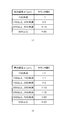
次に、制御部18は、記憶部19に記憶されている角加速度−カウンタ値対応テーブルを参照して、S22で求めた角加速度αに対応するカウンタ値Cを取得する(S23)。例えば、制御部18は、S22で求めた角加速度αが50[rpm]である場合、図3(a)に示す角加速度−カウンタ値対応テーブルを参照して、角加速度α[rpm]:「100未満」に対応するカウンタ値として「−1」を取得する。また、例えば、制御部18は、S22で求めた角加速度αが150[rpm]である場合、図3(a)に示す角加速度−カウンタ値対応テーブルを参照して、角加速度α[rpm]:「100以上、200未満」に対応するカウンタ値として「+3」を取得する。また、例えば、制御部18は、S22で求めた角加速度αが250[rpm]である場合、図3(a)に示す角加速度−カウンタ値対応テーブルを参照して、角加速度α[rpm]:「200以上、500未満」に対応するカウンタ値として「+15」を取得する。また、例えば、制御部18は、S22で求めた角加速度αが600[rpm]である場合、図3(a)に示す角加速度−カウンタ値対応テーブルを参照して、角加速度α[rpm]:「500以上」に対応するカウンタ値として「+30」を取得する。このように、本実施形態では、角加速度−カウンタ値対応テーブルを用いて、駆動輪16の角加速度αをカウンタ値Cに置き換えているため、カウンタ値として負の値や上限値を設定することができる。 なお、図3(b)に示す角加速度−カウンタ値対応テーブルのように、角加速度αとその角加速度αに対応するカウンタ値Cをさらに細かく設定してもよい。これにより、角加速度αの変化に積算値ΣCをより近づけることができるため、スリップ状態の判断精度を向上させることができる。また、図3(b)に示す角加速度−カウンタ値対応テーブルのように、角加速度αとその角加速度αに対応するカウンタ値Cをさらに細かく設定する場合であっても、閾値Cth2をカウンタ値Cの最大値よりも大きい値に設定する。
Next, the
次に、制御部18は、最初の制御タイミングから今回の制御タイミングまでに取得した全てのカウンタ値Cの積算値ΣCを算出する(S24)。例えば、制御部18は、図4に示すように、最初の制御タイミングt11で取得したカウンタ値Cが「+3」、前回の制御タイミングt12で取得したカウンタ値Cが「−1」、今回の制御タイミングt13で取得したカウンタ値Cが「+3」である場合、「+3」+「−1」+「+3」を計算することにより、今回の制御タイミングt13における積算値ΣCとして「+5」を求める。
Next, the
次に、制御部18のトルク取得部23は、記憶部19にトルクTが記憶されていない、すなわち、記憶部19内のトルクTがゼロであると判断し(S25がYes)、今回の制御タイミングで算出した積算値ΣCが閾値Cth1(第3の閾値)以上であると判断した場合(S26がYes)、そのときの電動機14のトルクTを記憶部19に記憶する(S27)。そのときのトルクTは、図示しない電流センサで測定した電動機14に流れる電流値や、回転数検出部17の値から算出することが出来る。例えば、トルク取得部23は、記憶部19内のトルクTがゼロであると判断し、図4に示すように、今回の制御タイミングt14で算出した積算値ΣCが「+20」である場合、その積算値ΣCが閾値Cth1:「+15」以上であると判断し、そのときの電動機14のトルクTを記憶部19に記憶する。なお、トルク取得部23は、記憶部19にトルクTがすでに記憶されていると判断した場合(S25がNo)、S26及びS27を実行しない。
Next, the
次に、スリップ判断部21は、今回の制御タイミングで算出した積算値ΣCが閾値Cth2(第1の閾値)(>閾値Cth1)よりも小さく(S28がNo)、かつ、閾値Cth3(第2の閾値)(<閾値Cth1)よりも大きいと判断した場合(S29がNo)、トルク制限フラグがオンであるか否かを判断する(S30)。なお、駆動輪16がスリップ状態であるか否かを判断するための閾値Cth2は、角加速度−カウンタ値対応テーブルに格納されるカウンタ値の最大値よりも大きい値に設定されるものとする。これにより、積算値ΣCを少なくとも2回算出しないと、駆動輪16がスリップ状態であるか否かを判断することができないようにすることができる。
Next, the
スリップ判断部21は、トルク制限フラグがオフであると判断した場合(S30がNo)、回転数N及び角加速度αをゼロにリセットした後(S31)、S21に戻る。例えば、スリップ判断部21は、図4に示すように、今回の制御タイミングt15で算出した積算値ΣCが「+50」である場合、その積算値ΣCが閾値Cth2:「+60」よりも小さく、かつ、閾値Cth3:「0」よりも大きいと判断するとともに、トルク制限フラグがオフであると判断すると、回転数N及び角加速度αをゼロにリセットした後、S21に戻る。
When the
一方、スリップ判断部21は、今回の制御タイミングで算出した積算値ΣCが閾値Cth2以上であると判断した場合、すなわち、スリップ状態であると判断した場合(S28がYes)、トルク制限フラグをオンし(S32)、S30へ進む。例えば、スリップ判断部21は、図4に示すように、今回の制御タイミングt16で算出した積算値ΣCが「+80」である場合、その積算値ΣCが閾値Cth2:「+60」以上であると判断し、トルク制限フラグをオンする。
On the other hand, when it is determined that the integrated value ΣC calculated at the current control timing is equal to or greater than the threshold value Cth2, that is, when it is determined that the slip state is present (S28 is Yes), the
また、スリップ判断部21は、今回の制御タイミングで算出した積算値ΣCが閾値Cth2よりも小さく(S28がNo)、かつ、今回の制御タイミングで算出した積算値ΣCが閾値Cth3以下であると判断した場合(S29がYes)、トルク制限解除フラグをオンし(S33)、S30へ進む。例えば、スリップ判断部21は、図4に示すように、今回の制御タイミングt96で算出した積算値ΣCが「0」である場合、その積算値ΣCが閾値Cth2:「+60」よりも小さく、かつ、閾値Cth3:「0」以下であると判断し、トルク制限解除フラグをオンする。
The
そして、トルク制限部22は、トルク制限フラグがオンであると判断し(S30がYes)、トルク制限解除フラグがオフであると判断した場合(S34がNo)、電動機14のトルクTが所定のトルクTに制限されるように、インバータ回路13の動作を制御し(S35)、回転数N及び角加速度αをゼロにリセットした後(S31)、S21に戻る。例えば、トルク制限部22は、トルク制限フラグがオンであると判断し、トルク制限解除フラグがオフであると判断した場合、電動機14のトルクTが記憶部19に記憶しておいたトルクTの50%の値に制限されるように、インバータ回路13の動作を制御する。
Then, when the
また、トルク制限部22は、トルク制限フラグがオンであると判断し(S30がYes)、トルク制限解除フラグもオンであると判断した場合(S34がYes)、電動機14のトルクTにかけていた制限を解除した後(S36)、積算値ΣC及びトルクTをゼロにリセットするとともに、トルク制限フラグ及びトルク制限解除フラグをオフする(S37)。その後、制御部18は、回転数N及び角加速度αをゼロにリセットした後(S31)、S21に戻る。
Further, when the
このように、本実施形態の制御装置15では、一定時間あたりの回転数Nの変化量、すなわち、角加速度αの増加に伴って値が大きくなるカウンタ値Cを予め用意しておき、そのカウンタ値Cの積算値ΣCが閾値Cth2以上になったとき、駆動輪16がスリップ状態であることを判断している。そのため、例えば、スリップし始めてから完全にスリップ状態になった直後の駆動輪16の角加速度αに対応するカウンタ値Cを閾値Cth2とすることで、駆動輪16がスリップ状態であることを精度良く判断することができる。これにより、スリップ状態時のトルク制限動作を迅速に行うことができるため、すぐに駆動輪16を路面にグリップさせることができる。従って、スリップ状態による駆動輪16の回転数Nの急激な増加を抑えることができるため、電動機14の回転数が制御可能な範囲から外れたり、駆動輪16と連動する部品へ過負荷がかかったりすることを抑制することができる。
As described above, in the
また、本実施形態の制御装置15では、閾値Cth2をカウンタ値Cの最大値をよりも大きくし、積算値ΣCを少なくとも2回求めないと駆動輪16がスリップ状態であるか否かを判断することができないようにしている。そのため、本実施形態の制御装置15では、駆動輪16の回転数が閾値以上になったとき駆動輪16がスリップ状態であることを判断する場合に比べて、スリップ状態であると判断する頻度を低減することができ、スリップ状態であることが頻繁に判断される際のトルク制限によるスムーズな走行の妨げを抑えることができる。
Further, in the
また、本実施形態の制御装置15では、角加速度−カウンタ値対応テーブルに格納される各角加速度αのうち所定の角加速度α(例えば、99[rpm])以下に対応するカウンタ値Cを負の値とし、積算値ΣCが閾値Cth2以上になった後、閾値Cth3以下になると、スリップ状態でないと判断してトルク制限を解除している。これにより、トルクを制限している間、スリップ状態が解消されて制御タイミング毎に取得されるカウンタ値Cが常に所定の角加速度α以下に対応するカウンタ値Cになる場合、少なくとも積算値ΣCが閾値Cth2から閾値Cth3に減少するまでにかかる時間を、カウンタ値Cを調整する事で任意に設定することができる。そして、例えば、スリップ状態であると判断されてトルクが制限されてからスリップ状態でないと判断されてトルク制限が解除されるまでの時間を、車両11の走行時におけるインバータ回路13の動作制御に影響が及ばない程度に十分に長い時間に設定することにより、路面状態が変化しないままトルク制限が解除されて再びスリップ状態になってしまうことを抑制することができ、同じ路面状態で連続してスリップ状態になってしまうことを抑えることができる。
In the
また、本実施形態の制御装置15では、電動機14のトルクTを制限する際、そのトルクTを記憶部19に記憶しておいたトルクTを利用して制限している。そして、例えば、記憶部19に記憶しておいたトルクTを、少なくとも積算値ΣCが増加し始めたときのトルクTよりも小さいトルクとすることにより、電動機14のトルクTが十分に制限されるため、すぐにスリップ状態が解消され駆動輪16を路面にグリップさせることができる。
In the
なお、上記実施形態では、図2に示すフローチャートのように、積算値ΣCが閾値Cth2以上になった後、閾値Cth3以下になると、トルク制限を解除する構成であるが、積算値ΣCが閾値Cth2以上になった後、一定期間経過後に、トルク制限を解除してもよい。このように構成する場合、記憶部19に予め記憶されている角加速度−カウンタ値対応テーブルのカウンタ値の最小値を負の値にする必要がなく、図2に示すS29、S30、S32、S33、S34を省略することができる。そのため、例えば、図5に示すフローチャートのS51〜S63のように、図2に示すフローチャートに比べて、制御部18の動作を簡略化することができる。なお、図5に示すS51〜S58は、図2に示すS21〜S28と同様とする。
In the above embodiment, as shown in the flowchart of FIG. 2, the torque limit is released when the integrated value ΣC becomes equal to or greater than the threshold value Cth2 after the integrated value ΣC becomes equal to or greater than the threshold value Cth2. After the above, the torque limitation may be released after a certain period of time has elapsed. In the case of such a configuration, it is not necessary to set the minimum value of the counter value of the angular acceleration-counter value correspondence table stored in advance in the
なお、上記実施形態では回転数検出部17は電動機14に配置され、電動機14の回転数を取得するようにしたが、例えば駆動輪16に配置し、駆動輪16の回転数を取得しても良い。しかし電動機14に配置したほうが、通常運転の電動機14の制御にもちいることができ好ましい。電動機14に配置する場合、駆動輪の回転数や角加速度等を得るのに減速比が必要になる。減速比が固定の場合はその値を記憶部19等に保存しておけばよいし、可変の場合は別途減速比情報を取得する手段(たとえば変速シフト位置情報等)から、またはその情報と減速比の関係から減速比を取得すればよい。
In the above embodiment, the rotational
なお、上記実施形態ではカウンタ値Cが負の値になるのを1段階にしたが複数段にしても良い。この場合、角加速度αに応じてトルク制限解除までの時間を変化させる事が出来る。 In the above embodiment, the counter value C has a negative value in one stage, but it may be in a plurality of stages. In this case, the time until the torque limit is released can be changed according to the angular acceleration α.
11 車両
12 バッテリ
13 インバータ回路
14 電動機
15 制御装置
16 駆動輪
17 回転数検出部
18 制御部
19 記憶部
20 角加速度取得部
21 スリップ判断部
22 トルク制限部
23 トルク取得部
DESCRIPTION OF SYMBOLS 11
Claims (8)
前記角加速度取得手段により取得される角加速度に対応するカウンタ値の積算値が第1の閾値以上になると、前記駆動輪がスリップ状態であると判断するスリップ判断手段と、
前記スリップ判断手段により前記駆動輪がスリップ状態であると判断されると、前記電動機のトルクを制限させるトルク制限手段と、
を備えることを特徴とする電気車両のスリップ抑制駆動制御装置。 Angular acceleration acquisition means for acquiring angular acceleration of driving wheels driven by torque of an electric motor mounted on the vehicle;
Slip determining means for determining that the drive wheel is in a slip state when an integrated value of counter values corresponding to the angular acceleration acquired by the angular acceleration acquiring means is equal to or greater than a first threshold;
Torque determining means for limiting the torque of the motor when the slip determining means determines that the drive wheel is in a slip state;
An anti-slip drive control apparatus for an electric vehicle, comprising:
前記第1の閾値は、前記カウンタ値の最大値よりも大きい
ことを特徴とする電気車両のスリップ抑制駆動制御装置。 The slip suppression drive control device according to claim 1,
The first threshold value is larger than a maximum value of the counter value. A slip suppression drive control device for an electric vehicle, wherein:
前記角加速度取得手段により取得される角加速度に対応する前記カウンタ値のうち所定の角加速度以下に対応する前記カウンタ値は、負の値であり、
前記スリップ判断手段は、前記積算値が前記第1の閾値よりも小さい第2の閾値以下になると、前記駆動輪がスリップ状態でないと判断し、
前記トルク制限手段は、前記スリップ判断手段により前記駆動輪がスリップ状態であると判断された後、前記駆動輪がスリップ状態でないと判断されると、前記電動機のトルク制限を解除させる
ことを特徴とする電気車両のスリップ抑制駆動制御装置。 The slip suppression drive control device according to claim 1,
Of the counter values corresponding to the angular acceleration acquired by the angular acceleration acquiring means, the counter value corresponding to a predetermined angular acceleration or less is a negative value.
The slip determination means determines that the drive wheel is not in a slip state when the integrated value is equal to or less than a second threshold value that is smaller than the first threshold value,
The torque limiting means releases the torque limit of the motor when the slip determining means determines that the drive wheel is in a slip state and then determines that the drive wheel is not in a slip state. An anti-slip drive control device for an electric vehicle.
前記積算値が前記第1の閾値よりも小さく、かつ、前記第2の閾値よりも大きい第3の閾値以上になるときの前記トルクを取得するトルク取得手段をさらに備え、
前記トルク制限手段は、前記スリップ判断手段により前記駆動輪がスリップ状態であると判断されると、前記電動機のトルクを前記トルク取得手段により取得されたトルクに基づいた値に制限させる
ことを特徴とする電気車両のスリップ抑制駆動制御装置。 The slip suppression drive control device according to claim 1,
Torque acquisition means for acquiring the torque when the integrated value is smaller than the first threshold and greater than or equal to a third threshold greater than the second threshold;
The torque limiting means limits the torque of the electric motor to a value based on the torque acquired by the torque acquiring means when the slip determining means determines that the drive wheel is in a slip state. An anti-slip drive control device for an electric vehicle.
前記角加速度に対応するカウンタ値の積算値が第1の閾値以上になると、前記駆動輪がスリップ状態であると判断し、
前記駆動輪がスリップ状態であると判断すると、前記電動機のトルクを制限させる
ことを特徴とする電気車両のスリップ抑制方法。 Obtain the angular acceleration of the drive wheels that are driven by the torque of the motor mounted on the vehicle,
When the integrated value of the counter value corresponding to the angular acceleration is equal to or greater than a first threshold, it is determined that the drive wheel is in a slip state,
When it is determined that the drive wheel is in a slip state, the torque of the electric motor is limited.
前記第1の閾値は、前記カウンタ値の最大値よりも大きい
ことを特徴とする電気車両のスリップ抑制方法。 The slip suppression method according to claim 5,
The first threshold value is larger than the maximum value of the counter value.
前記角加速度取得手段により取得される角加速度に対応する前記カウンタ値のうち所定の角加速度以下に対応する前記カウンタ値は、負の値であり、
前記積算値が前記第1の閾値よりも小さい第2の閾値以下になると、前記駆動輪がスリップ状態でないと判断し、
前記駆動輪がスリップ状態であると判断した後、前記駆動輪がスリップ状態でないと判断すると、前記電動機のトルク制限を解除させる
ことを特徴とする電気車両のスリップ抑制方法。 The slip suppression method according to claim 5,
Of the counter values corresponding to the angular acceleration acquired by the angular acceleration acquiring means, the counter value corresponding to a predetermined angular acceleration or less is a negative value.
When the integrated value is equal to or less than a second threshold value that is smaller than the first threshold value, it is determined that the driving wheel is not in a slip state,
After determining that the drive wheel is in a slip state, if the drive wheel is determined not to be in a slip state, the torque limit of the electric motor is released.
前記積算値が前記第1の閾値よりも小さく、かつ、前記第2の閾値よりも大きい第3の閾値以上になるときの前記トルクを取得し、
前記駆動輪がスリップ状態であると判断すると、前記電動機のトルクを前記取得したトルクに基づいた値に制限させる
ことを特徴とする電気車両のスリップ抑制方法。
The slip suppression method according to claim 5,
Obtaining the torque when the integrated value is smaller than the first threshold and greater than or equal to a third threshold greater than the second threshold;
If it is determined that the driving wheel is in a slip state, the electric vehicle slip is limited to a value based on the acquired torque.
Priority Applications (1)
| Application Number | Priority Date | Filing Date | Title |
|---|---|---|---|
| JP2012150359A JP2014014221A (en) | 2012-07-04 | 2012-07-04 | Slip suppression drive control device and slip suppression method for electric vehicle |
Applications Claiming Priority (1)
| Application Number | Priority Date | Filing Date | Title |
|---|---|---|---|
| JP2012150359A JP2014014221A (en) | 2012-07-04 | 2012-07-04 | Slip suppression drive control device and slip suppression method for electric vehicle |
Publications (1)
| Publication Number | Publication Date |
|---|---|
| JP2014014221A true JP2014014221A (en) | 2014-01-23 |
Family
ID=50109555
Family Applications (1)
| Application Number | Title | Priority Date | Filing Date |
|---|---|---|---|
| JP2012150359A Pending JP2014014221A (en) | 2012-07-04 | 2012-07-04 | Slip suppression drive control device and slip suppression method for electric vehicle |
Country Status (1)
| Country | Link |
|---|---|
| JP (1) | JP2014014221A (en) |
Cited By (5)
| Publication number | Priority date | Publication date | Assignee | Title |
|---|---|---|---|---|
| EP3006258A1 (en) * | 2013-06-03 | 2016-04-13 | NTN Corporation | Slip control device for electric vehicle |
| CN109533156A (en) * | 2017-09-20 | 2019-03-29 | 北京凌云智能科技有限公司 | The judgment method and balance car of balance car wheel skid |
| CN112549992A (en) * | 2020-12-18 | 2021-03-26 | 智新控制系统有限公司 | Creep control method and system for ramp-free sensor of pure electric vehicle |
| CN112758096A (en) * | 2021-02-19 | 2021-05-07 | 安徽安凯汽车股份有限公司 | Intelligent drive anti-skid control system and method based on motor torque control |
| WO2023222039A1 (en) * | 2022-05-20 | 2023-11-23 | 比亚迪股份有限公司 | Vehicle trackslip identification method, vehicle trackslip processing apparatus, and vehicle |
Citations (5)
| Publication number | Priority date | Publication date | Assignee | Title |
|---|---|---|---|---|
| JP2004092580A (en) * | 2002-09-03 | 2004-03-25 | Toyota Motor Corp | Vehicle control device and its control method |
| JP2006136177A (en) * | 2004-11-09 | 2006-05-25 | Nissan Motor Co Ltd | Motor traction controller of vehicle |
| JP2007185071A (en) * | 2006-01-10 | 2007-07-19 | Toyota Motor Corp | Controller of motor |
| JP2011105071A (en) * | 2009-11-13 | 2011-06-02 | Honda Motor Co Ltd | Control device of inverted-pendulum type vehicle |
| JP2012076510A (en) * | 2010-09-30 | 2012-04-19 | Aisin Aw Co Ltd | Control device |
-
2012
- 2012-07-04 JP JP2012150359A patent/JP2014014221A/en active Pending
Patent Citations (5)
| Publication number | Priority date | Publication date | Assignee | Title |
|---|---|---|---|---|
| JP2004092580A (en) * | 2002-09-03 | 2004-03-25 | Toyota Motor Corp | Vehicle control device and its control method |
| JP2006136177A (en) * | 2004-11-09 | 2006-05-25 | Nissan Motor Co Ltd | Motor traction controller of vehicle |
| JP2007185071A (en) * | 2006-01-10 | 2007-07-19 | Toyota Motor Corp | Controller of motor |
| JP2011105071A (en) * | 2009-11-13 | 2011-06-02 | Honda Motor Co Ltd | Control device of inverted-pendulum type vehicle |
| JP2012076510A (en) * | 2010-09-30 | 2012-04-19 | Aisin Aw Co Ltd | Control device |
Cited By (7)
| Publication number | Priority date | Publication date | Assignee | Title |
|---|---|---|---|---|
| EP3006258A1 (en) * | 2013-06-03 | 2016-04-13 | NTN Corporation | Slip control device for electric vehicle |
| EP3006258A4 (en) * | 2013-06-03 | 2017-03-29 | NTN Corporation | Slip control device for electric vehicle |
| CN109533156A (en) * | 2017-09-20 | 2019-03-29 | 北京凌云智能科技有限公司 | The judgment method and balance car of balance car wheel skid |
| CN112549992A (en) * | 2020-12-18 | 2021-03-26 | 智新控制系统有限公司 | Creep control method and system for ramp-free sensor of pure electric vehicle |
| CN112549992B (en) * | 2020-12-18 | 2022-04-01 | 智新控制系统有限公司 | Creep control method and system for ramp-free sensor of pure electric vehicle |
| CN112758096A (en) * | 2021-02-19 | 2021-05-07 | 安徽安凯汽车股份有限公司 | Intelligent drive anti-skid control system and method based on motor torque control |
| WO2023222039A1 (en) * | 2022-05-20 | 2023-11-23 | 比亚迪股份有限公司 | Vehicle trackslip identification method, vehicle trackslip processing apparatus, and vehicle |
Similar Documents
| Publication | Publication Date | Title |
|---|---|---|
| TWI531506B (en) | Motor drive control device | |
| JP6098723B2 (en) | Vehicle control apparatus and vehicle control method | |
| JP2014014221A (en) | Slip suppression drive control device and slip suppression method for electric vehicle | |
| US20150012160A1 (en) | Damping control device and damping control method for vehicle using electric motor | |
| WO2011089830A1 (en) | Electrically driven vehicle | |
| RU2017141372A (en) | CONTROL DEVICE FOR ELECTRIC VEHICLE AND CONTROL METHOD FOR ELECTRIC VEHICLE | |
| JPWO2015105077A1 (en) | Electric vehicle control device and electric vehicle control method | |
| EP3459782B1 (en) | Motor driving control apparatus and method and motor-assisted vehicle | |
| TWI733136B (en) | Motor control device, method and electric auxiliary vehicle | |
| JP6605031B2 (en) | Electric vehicle moving direction detection | |
| EP3212460B1 (en) | System for piloting an electric motor in electric motorcycles or the like | |
| JPWO2017033753A1 (en) | Control method and control apparatus for electric vehicle | |
| JP2017028905A (en) | Regeneration control device for vehicle | |
| JPWO2015136664A1 (en) | Vehicle control apparatus and vehicle control method | |
| US11161418B2 (en) | Control device of electric vehicle | |
| WO2019189285A1 (en) | Motor control device and electrically assisted vehicle | |
| JP2010030437A (en) | Vehicle condition display apparatus and method of parallel two-wheeled vehicle | |
| CN105473439A (en) | Motor drive control device and electrically assisted vehicle | |
| JP6589554B2 (en) | Control method and control apparatus for electric vehicle | |
| JP6036639B2 (en) | Vehicle control device | |
| JP6254878B2 (en) | Electric assist bicycle | |
| JP5219103B2 (en) | Travel control device | |
| JP6219326B2 (en) | Motorcycle | |
| JP5229884B2 (en) | Control device for hybrid vehicle | |
| JP2005335534A (en) | Vehicle with auxiliary power unit |
Legal Events
| Date | Code | Title | Description |
|---|---|---|---|
| A621 | Written request for application examination |
Free format text: JAPANESE INTERMEDIATE CODE: A621 Effective date: 20150512 |
|
| A977 | Report on retrieval |
Free format text: JAPANESE INTERMEDIATE CODE: A971007 Effective date: 20160120 |
|
| A131 | Notification of reasons for refusal |
Free format text: JAPANESE INTERMEDIATE CODE: A131 Effective date: 20160202 |
|
| A02 | Decision of refusal |
Free format text: JAPANESE INTERMEDIATE CODE: A02 Effective date: 20160802 |