JP2014013307A - Hologram manufacturing device and hologram manufacturing method - Google Patents
Hologram manufacturing device and hologram manufacturing method Download PDFInfo
- Publication number
- JP2014013307A JP2014013307A JP2012150463A JP2012150463A JP2014013307A JP 2014013307 A JP2014013307 A JP 2014013307A JP 2012150463 A JP2012150463 A JP 2012150463A JP 2012150463 A JP2012150463 A JP 2012150463A JP 2014013307 A JP2014013307 A JP 2014013307A
- Authority
- JP
- Japan
- Prior art keywords
- hologram
- belt
- sensitive material
- light
- support members
- Prior art date
- Legal status (The legal status is an assumption and is not a legal conclusion. Google has not performed a legal analysis and makes no representation as to the accuracy of the status listed.)
- Pending
Links
Images


Abstract
Description
本発明は、ホログラム原版を用いてホログラム感材を露光することによりホログラムを製造するホログラム製造装置およびホログラム製造方法に関する。 The present invention relates to a hologram manufacturing apparatus and a hologram manufacturing method for manufacturing a hologram by exposing a hologram sensitive material using a hologram master.
例えば特許文献1〜3に開示されているように、参照光およびホログラム原版からの再生光を複製用のホログラム感材に露光することによって、ホログラム感材に干渉縞を記録し、ホログラムを製造する方法が知られている。特許文献1および特許文献2には、平板状のホログラム原版を用いる方法が開示されており、特許文献3には、ドラム上に配置された湾曲状のホログラム原版を用いる方法が開示されている。 For example, as disclosed in Patent Documents 1 to 3, an interference fringe is recorded on the hologram sensitive material by exposing the reproduction light from the reference light and the hologram original plate to the hologram sensitive material for duplication, thereby producing a hologram. The method is known. Patent Documents 1 and 2 disclose a method using a flat hologram master, and Patent Document 3 discloses a method using a curved hologram original disposed on a drum.
ただし、特許文献1および特許文献2に開示された方法では、平板状のホログラム原版上にホログラム感材を配置する工程と、ホログラム原版上のホログラム感材を露光する工程と、露光済みのホログラム感材をホログラム原版上から回収する工程とを、ホログラムを製造する度に、順に実施していかなくてはならない。このため、ホログラム感材を間欠的に搬送しながら、ホログラムを順に製造していくことになる。したがって、特許文献1および特許文献2に開示された方法では、生産効率を大幅に上昇させることができない。 However, in the methods disclosed in Patent Document 1 and Patent Document 2, a step of arranging a hologram sensitive material on a plate-shaped hologram master, a step of exposing a hologram sensitive material on a hologram original, and an exposed hologram feeling The process of recovering the material from the hologram master must be performed in turn each time the hologram is manufactured. For this reason, holograms are sequentially manufactured while intermittently conveying the hologram sensitive material. Therefore, the methods disclosed in Patent Document 1 and Patent Document 2 cannot significantly increase production efficiency.
また、特許文献3に開示された方法では、ドラム上に配置された湾曲状のホログラム原版を含むドラムの外周面上に、ウェブ状のホログラム感材が巻き付くようにして配置される。そして、ホログラム感材は、ドラムが回転することにより移動し、所定の区間を通過する際に露光される。特許文献3に開示された方法によれば、ウェブ状のホログラム感材へ干渉縞を連続的に記録していき、ホログラムを連続的に製造していくことができる。 Further, in the method disclosed in Patent Document 3, the web-shaped hologram sensitive material is disposed around the outer peripheral surface of the drum including the curved hologram master disposed on the drum. The hologram photosensitive material moves when the drum rotates, and is exposed when passing through a predetermined section. According to the method disclosed in Patent Document 3, it is possible to continuously record interference fringes on a web-shaped hologram sensitive material and to produce holograms continuously.
しかしながら、特許文献3に開示された方法では、露光されるホログラム感材が湾曲している。このため、露光用の光として平行光束を用いた場合には、ホログラム感材の移動にともなって、ホログラム感材の所定の箇所を露光する光の入射角度が変化する。このため、高い回折効率で所望の回折現象を引き起こすホログラムを製造することができない。また、特許文献3に開示された方法では、ホログラム感材に対する参照光の入射方向に、制約が生じてしまう。とりわけ、参照光を平行光束にしたとしても、参照光の入射方向を自由に設定することは極めて困難となる。 However, in the method disclosed in Patent Document 3, the exposed hologram sensitive material is curved. For this reason, when a parallel light beam is used as the exposure light, the incident angle of light for exposing a predetermined portion of the hologram sensitive material changes with the movement of the hologram sensitive material. For this reason, it is impossible to manufacture a hologram that causes a desired diffraction phenomenon with high diffraction efficiency. In the method disclosed in Patent Document 3, there is a restriction on the incident direction of the reference light with respect to the hologram photosensitive material. In particular, even if the reference light is a parallel light beam, it is extremely difficult to freely set the incident direction of the reference light.
本発明は以上の点を考慮してなされたものであり、高い回折効率を有するホログラムを高い生産効率で製造することができるホログラム製造装置およびホログラム製造方法を提供することを目的とする。 The present invention has been made in consideration of the above points, and an object thereof is to provide a hologram manufacturing apparatus and a hologram manufacturing method capable of manufacturing a hologram having high diffraction efficiency with high production efficiency.
本発明によるホログラム製造装置は、
二以上の支持部材と、
前記二以上の支持部材によって移動可能に支持されたベルトであって、前記二以上の支持部材に架け渡された環状のベルト本体と、前記ベルト本体に保持されたホログラム原版と、を有する環状のベルトと、
前記ベルトの移動経路のうちの隣り合う二つの支持部材の間となる一区間を含む領域に向け平行光束を照射し、前記ベルト上に供給されたホログラム感材を露光する露光装置と、を備える。
The hologram manufacturing apparatus according to the present invention includes:
Two or more support members;
A belt movably supported by the two or more support members, the belt having an annular belt body spanned between the two or more support members, and a hologram original plate held by the belt body Belt,
An exposure device that irradiates a parallel luminous flux toward a region including a section between two adjacent support members in the belt movement path, and exposes the hologram photosensitive material supplied on the belt. .
本発明によるホログラム製造装置において、前記供給されるホログラム感材が、接着性を有しており、前記ベルトに接着した状態で前記ベルトとともに移動するようにしてもよい。 In the hologram manufacturing apparatus according to the present invention, the supplied hologram sensitive material may have adhesiveness and move together with the belt while being adhered to the belt.
本発明によるホログラム製造装置が、前記ホログラム感材を前記ベルト上へ供給する供給装置であって、前記ホログラム感材と前記ホログラム感材を挟持するセパレータおよび支持体とを含む元材を供給する元材供給機構と、前記元材供給機構から供給される前記元材の前記セパレータを前記ホログラム感材から剥離させて回収するセパレータ回収機構と、を有する供給装置を、さらに備えるようにしてもよい。 The hologram manufacturing apparatus according to the present invention is a supply device that supplies the hologram sensitive material onto the belt, and supplies a base material including the hologram sensitive material, a separator that sandwiches the hologram sensitive material, and a support. You may make it further provide the supply apparatus which has a material supply mechanism and the separator collection | recovery mechanism which peels and isolate | separates the said separator of the said original material supplied from the said original material supply mechanism from the said hologram sensitive material.
本発明によるホログラム製造装置が、露光された前記ホログラム感材を前記ベルトから剥離させて回収する回収装置であって、前記ホログラム感材の前記ベルトに接着していた面に合紙を積層して回収する回収装置を、さらに備えるようにしてもよい。 The hologram manufacturing apparatus according to the present invention is a collection device for separating and recovering the exposed hologram sensitive material from the belt, and laminating slip sheets on the surface of the hologram sensitive material adhered to the belt. You may make it further provide the collection | recovery apparatus which collect | recovers.
本発明によるホログラム製造装置において、前記ホログラム原版の表面に剥離処理が施されていてもよいし、或いは、前記ホログラム原版の前記ホログラム感材と対面する側に剥離層が設けられていてもよい。 In the hologram manufacturing apparatus according to the present invention, the surface of the hologram original plate may be subjected to a release treatment, or a release layer may be provided on the side of the hologram original plate facing the hologram sensitive material.
本発明によるホログラム製造装置が、前記ホログラム感材を回収された後の前記ベルトを洗浄する洗浄装置を、さらに備えるようにしてもよい。 The hologram manufacturing apparatus according to the present invention may further include a cleaning device for cleaning the belt after the hologram sensitive material is collected.
本発明によるホログラム製造装置が、前記ベルトの移動経路に沿って前記隣り合う二つの支持部材の間となる位置に設けられ、前記環状のベルトに内面側から当接する面を有した支持台を、さらに備え、
前記露光装置は、前記支持台上に位置にしている前記ベルト上のホログラム感材に平行光束を照射するようにしてもよい。
A hologram manufacturing apparatus according to the present invention is provided at a position between the two adjacent support members along the movement path of the belt, and a support base having a surface that comes into contact with the annular belt from the inner surface side, In addition,
The exposure apparatus may irradiate the hologram light-sensitive material on the belt positioned on the support base with a parallel light beam.
本発明によるホログラム製造装置において、前記ベルトは、前記露光装置から照射された光のうちの前記ホログラム原版を透過した0次光の反射を抑制する手段を、さらに有するようにしてもよい。 In the hologram manufacturing apparatus according to the present invention, the belt may further include means for suppressing reflection of zero-order light transmitted through the hologram original plate out of light irradiated from the exposure apparatus.
本発明によるホログラム製造方法は、
ホログラム原版を有するベルトであって、二以上の支持部材に支持されて移動する環状のベルト上に、ホログラム感材を供給する工程と、
前記ベルトの移動経路に沿って隣り合う二つの支持部材の間を前記ベルトに支持されて移動しているホログラム感材に平行光束を照射して、前記ホログラム感材を露光する工程と、
露光されたホログラム感材を前記ベルト上から回収する工程と、を備える。
The hologram manufacturing method according to the present invention comprises:
Supplying a hologram sensitive material onto an annular belt which is a belt having a hologram original plate and moves while being supported by two or more support members;
Irradiating the hologram light-sensitive material that is moving while being supported by the belt between two adjacent support members along the movement path of the belt, and exposing the hologram light-sensitive material;
Recovering the exposed hologram sensitive material from the belt.
本発明によるホログラム製造方法において、接着性を有したホログラム感材が前記ベルト上に供給され、前記ホログラム感材は、前記ベルトに接着した状態で、前記ベルトとともに移動するようにしてもよい。 In the hologram manufacturing method according to the present invention, an adhesive hologram sensitive material may be supplied onto the belt, and the hologram sensitive material may be moved together with the belt while being adhered to the belt.
本発明によるホログラム製造方法において、前記ホログラム感材と前記ホログラム感材を挟持するセパレータおよび支持体とを含む元材をまず供給し、その後に元材から前記セパレータを除去して、前記ホログラム感材を前記ベルト上に供給するようにしてもよい。 In the hologram manufacturing method according to the present invention, first, a base material including the hologram sensitive material, a separator for sandwiching the hologram sensitive material, and a support is supplied, and then the separator is removed from the base material. May be supplied onto the belt.
本発明によるホログラム製造方法において、露光された前記ホログラム感材を、前記ベルトから剥離させて、合紙を積層して回収するようにしてもよい。 In the hologram manufacturing method according to the present invention, the exposed hologram sensitive material may be peeled off from the belt, and the slip sheets may be stacked and collected.
本発明によるホログラム製造方法において、前記ホログラム原版の表面に剥離処理が施されていてもよいし、或いは、前記ホログラム原版の前記ホログラム感材と対面する側に剥離層が設けられていてもよい。 In the hologram manufacturing method according to the present invention, the surface of the hologram original plate may be subjected to a release treatment, or a release layer may be provided on the side of the hologram original plate facing the hologram sensitive material.
本発明によるホログラム製造方法が、前記ホログラム感材を回収された後の前記ベルトを洗浄する工程を、さらに備えるようにしてもよい。 The hologram manufacturing method according to the present invention may further include a step of cleaning the belt after the hologram sensitive material is collected.
本発明によるホログラム製造方法において、前記ベルトの移動経路に沿って前記隣り合う二つの支持部材の間となる位置に設けられ支持台の前記環状のベルトに内面側から当接する面上を、前記ベルトに支持されて移動しているホログラム感材に平行光束を照射するようにしてもよい。 In the hologram manufacturing method according to the present invention, the belt is provided on a surface that is provided at a position between the two adjacent support members along the belt movement path and comes into contact with the annular belt of the support base from the inner surface side. A parallel luminous flux may be irradiated onto the hologram sensitive material that is supported and moving.
本発明によるホログラム製造方法において、ホログラム感材に平行光束を照射している際に前記ホログラム原版を透過した0次光の反射を、前記ベルトに設けられた手段によって、抑制するようにしてもよい。 In the hologram manufacturing method according to the present invention, the reflection of the zero-order light transmitted through the hologram original plate may be suppressed by means provided on the belt when the hologram light-sensitive material is irradiated with a parallel light beam. .
本発明によれば、高い回折効率を有するホログラムを高い生産効率で製造することができる。 According to the present invention, a hologram having high diffraction efficiency can be manufactured with high production efficiency.
図1〜図4は本発明による一実施の形態を説明するための図である。以下、図面を参照して本発明の一実施の形態について説明する。なお、本件明細書に添付する図面においては、図示と理解のしやすさの便宜上、適宜縮尺および縦横の寸法比等を、実物のそれらから変更し誇張してある。 1 to 4 are diagrams for explaining an embodiment according to the present invention. Hereinafter, an embodiment of the present invention will be described with reference to the drawings. In the drawings attached to the present specification, for the sake of illustration and ease of understanding, the scale, the vertical / horizontal dimension ratio, and the like are appropriately changed and exaggerated from those of the actual product.
なお、以下においては、リップマンホログラムとも呼ばれる反射型の体積ホログラム85を製造するための装置および方法について説明する。以下に説明する装置および方法は、後述の説明から明らかになるように、とりわけ反射型の体積ホログラム85に好適に適用され得る。まず、ホログラム85の製造に用いられるホログラム製造装置10について説明し、その後に、ホログラム製造方法について説明する。
In the following, an apparatus and a method for manufacturing a
ホログラム製造装置10は、二以上の支持部材12,13と、二以上の支持部材12,13によって移動可能に支持された環状のベルト20と、ベルト20の移動経路のうちの隣り合う二つの支持部材12,13の間となる一区間に向け平行光束を照射しベルト20上に供給されたホログラム感材80を露光する露光装置18と、を有している。ベルト20は、一以上のホログラム原版30を含んでいる。また、ホログラム製造装置10は、ホログラム感材80をベルト20上へ供給する供給装置50と、露光されたホログラム感材80をベルト20から剥離させて回収する回収装置60と、をさらに備えている。
The
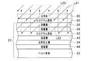
このホログラム製造装置10では、ホログラム感材80が、ベルト20上にてホログラム原版30と重ねられた状態にて、露光される。この際、図2に示すように、露光装置18から照射される光L21が参照光として、またホログラム感材80をいったん透過してホログラム原版30で回折された回折光L23が物体光として、ホログラム感材80に入射する。露光装置18からの光L21と回折光L23とが干渉することにより、ホログラム感材80内に明暗パターンである干渉縞が生成される。そして、この干渉縞が、感光性を有したホログラム感材80に記録される。このようにして、ホログラム感材80に干渉縞を記録することにより、ホログラム85が製造される。
In this
以下、ホログラム製造装置10の各部の構成について、詳述していく。
Hereinafter, the configuration of each part of the
供給装置50は、ウェブ状のホログラム感材80、言い換えると長尺でロール状に巻き取られたホログラム感材80を、ベルト20上に供給していく。ホログラム感材80は、例えば、銀塩乳剤や重クロム酸ゼラチン等の種々の公知の複製用ホログラム感材を用いることができるが、とりわけ、回折効率および取り扱い性の面で優れたフォトポリマーを好適に用いることができる。
The
加えて、ここで説明する形態において、ホログラム感材80は、接着性を有しており、ベルト20に向けていったん加圧されると当該ベルト20に接着するようになっている。なお、ここで用いる「接着性」とは、別途の接着剤を塗布することなく、ベルト20に向けていったん加圧することによりベルト20に接着し得る性質のことをいう。なお、本件明細書で用いる「接着」、「接着性」および「接着剤」との用語は、それぞれ、「粘着」、「粘着性」および「粘着剤」の意味を含むものとする。
In addition, in the embodiment described here, the hologram
図1に示された形態において、供給装置50は、ホログラム感材80を含む積層体として構成された元材78を供給する元材供給機構52と、元材供給機構52から供給される元材78のセパレータ83をホログラム感材80から剥離させて回収するセパレータ回収機構54と、を有している。図3に示されるように、ここで説明する例では、元材78は、支持体82と、ホログラム感材80と、セパレータ83と、をこの順番で含んでいる。支持体82およびセパレータ83は、ホログラム感材80を保護するための保護層として機能する。支持体82は、例えば樹脂フィルムから構成され得る。セパレータ83は、接着性を有したホログラム感材80に対する剥離性を有しており、例えば、剥離処理を施された樹脂フィルムから構成され得る。
In the form shown in FIG. 1, the
図1に示す例において、供給装置50は、元材供給機構を構成する元材供給ロール52と、セパレータ回収機構を構成するセパレータ回収ロール54と、元材78を誘導する供給案内ロール56a,56b,56cと、を含んでいる。元材78は、第1供給案内ロール56aおよび第2供給案内ロール56bを通過して、セパレータ83を剥がされる。セパレータ83を剥がされた元材78、すなわち、ホログラム感材80および支持体82の積層体は、第1供給案内ロール56aおよび第3供給案内ロール56cのそれぞれによってベルト20に向けて加圧されている。このため、ホログラム感材80および支持体82の積層体は、第1供給案内ロール56aを通過した後、ベルト20上に接着して、ベルト20と同期して移動するようになる。
In the example shown in FIG. 1, the
次に、ベルト20を支持して搬送する支持部材12,13について説明する。支持部材12,13は、例えば、その中心軸線を中心として回転可能に構成された支持ロール12,13として形成され得る。この形態においては、二以上の支持ロール12,13のうち一以上が駆動ロールとして機能し、その他のロールが従動ロールとして機能することにより、支持したベルト20を移動させることが可能となる。図1に示された形態では、二本の支持ロール12,13が、環状のベルト20を移動可能に支持する支持部材として、設けられている。
Next, the
次に、ベルト20について説明する。図2に示すように、ベルト20は、環状のベルト本体22と、ベルト本体22に保持されたホログラム原版30と、を有している。環状のベルト本体22は、二以上の支持部材12,13に架け渡されており、二以上の支持部材12,13によって画成される移動経路に沿って移動可能となっている。環状のベルト本体22は、帯状のベルトの両端を接続することによって、形成されていてもよい。帯状のベルトの両端を接続する場合には、ベルト本体22の表面に凹凸が生じないよう、ベルトの側端面同士を対面させるようにして接続することが好ましい。
Next, the
ベルト本体22として、例えば、金属製ベルトを利用することができる。帯状の金属製ベルトの両端を接続してベルト本体22を作製する方法としては、当該帯状の金属製ベルトの両端を溶接にて接続し、その後に、表面を平坦化するために溶接部分を研磨する方法が例示される。また別の方法として、帯状の金属製ベルトの両端を溶接にて接続し、その後に、厚みを均一化するために溶接部分を圧延する方法が例示される。さらに別の方法として、帯状の金属製ベルトの両端を圧延にて接続する方法も例示される。
For example, a metal belt can be used as the
ベルト本体22上には、一以上のホログラム原版30が貼合されている。ベルト本体22の外周面上に、より多くのホログラム原版30が設けられていることが好ましく、ベルト本体22の外周面上にホログラム原版30が隙間無く敷き詰められていることがより好ましい。このような形態によれば、供給装置50から連続的に繰り出されるホログラム感材80の使用効率、すなわち使用歩留まりを上昇させることができ、且つ、同一時間でより多くのホログラム85を作製することも可能となる。
One or
なお、ベルト20は、ホログラム原版30に加えて、種々の機能を期待された層を含むようにしてもよい。一例として図2に示されたベルト20は、接着性を有したホログラム感材80に接触するようになる層としての剥離層26と、ホログラム原版30とベルト本体22との間に設けられた反射防止層24と、を含んでいる。なお、ベルト20に含まれる各層26,30,24およびベルト本体22は、接着層38,42,44を介して、互いに接着されている。すなわち、図2に示されたベルト20は、剥離層26、第1接着層38、ホログラム原版30、第2接着層42、反射防止層24、第3接着層44およびベルト本体22を、この順番で含んでいる。ホログラム原版30以外の層26,38,42,24,44は、各ホログラム原版30に対応して、ベルト本体22上に一以上保持されるようにしてもよい。
The
図示された例において、ホログラム感材80は、ベルト20に剥離層26の側から接着され、その後、ベルト20の剥離層26から剥がされるようになる。つまり、ここで用いる「ベルトに積層される」とは、ベルト本体22上に積層されることだけを意味するものではなく、ベルト20に含まれるいずれかの層に積層されることを意味する。また、ここで用いる「ベルトから剥がされる」または「ベルトから剥離される」とは、ベルト本体22から剥がされる又は剥離されることだけを意味するものではなく、ベルト20に含まれるいずれかの層から剥がされる又は剥離されることを意味する。
In the illustrated example, the hologram
剥離層26として、例えば、ホログラム感材80に対面する側の面に剥離処理を施された樹脂フィルムを用いることができる。このような剥離層26をベルト20の最表面に設けることによって、ホログラム感材80を露光した後、接着性を有したホログラム感材80を損傷することなくベルト20から剥がすことができる。反射防止層24は、露光に用いられる光の反射を防止する手段としての一例である。反射防止層24は、例えば、可視光吸収性を有した黒色の樹脂フィルムから構成され得る。
As the
また、後述するように、ホログラム感材80を露光するための光は、剥離層26および第1接着層38を介してホログラム感材80へ入射する。したがって、露光装置18からの光の有効利用を図る上で、剥離層26および第1接着層38は、露光装置18からの光に対する透過性を有していることが好ましい。
Further, as will be described later, the light for exposing the hologram
ここで、図4を参照して、図2に示された層構成のベルト20を作製する方法の一例について説明する。まず、図4に示すように、マスター原版34、原版用感材31および支持体32をこの順番で含む積層体S1を用意する。支持体32は、原版用感材31を支持する層である。原版用感材31は、所望の干渉縞を記録されることによってホログラム原版30を形成するようになる層であり、上述したホログラム感材80と同様の材料を用いて作製され得る。マスター原版34は、ホログラム原版30に記録される干渉縞に対応した干渉縞を有するホログラムである。この積層体S1に対して、支持体32の側からコヒーレント光を照射して、原版用感材31を露光する。この際、コヒーレント光の積層体S1への入射方向は、支持体32および原版用感材31を透過した光が、マスター原版34に入射する際に当該マスター原版34に記録された干渉縞のブラッグ条件を満たすよう、決定される。この露光によって、支持体32を透過して原版用感材31に入射する光と、原版用感材31を透過した後にマスター原版34で回折されて原版用感材31に再入射する光とが干渉して、明暗のパターンが原版用感材31に生成される。このパターンに対応した干渉縞が原版用感材31に記録され、ホログラム原版30が得られる。
Here, with reference to FIG. 4, an example of a method for producing the
積層体S1の露光が終了した後、マスター原版34を取り除いて合紙36を積層する。得られた積層体S2に対して、後処理、例えば、加熱処理およびUV光照射処理を施し、ホログラム原版30の感光性を消失させる。その後、積層体S2から合紙36を剥がして、代わりに、第1接着層38およびセパレータ40を積層し、積層体S3を得る。その後、積層体S3の支持体32を剥がして、代わりに、第2接着層42および反射防止層24を積層し、積層体S4を得る。次に、積層体S4の反射防止層24の側へ、第3接着層44およびセパレータ46を積層し、積層体S5を得る。その後、積層体S5の第1接着層38側のセパレータ40を剥がして、代わりに、剥離層26を積層し、積層体S6を得る。得られた積層体S6の第3接着層44側のセパレータ46を剥がした後に、第3接着層44を介して、この積層体S6をベルト本体22に貼合する。積層体S6を所望の数だけ、ベルト本体22上に配置することにより、ベルト20が得られる。
After the exposure of the laminated body S1 is completed, the master
次に、露光装置18について説明する。露光装置18は、ベルト20上に支持されたホログラム感材80に対して、干渉性を有したコヒーレント光からなる平行光束を照射するように構成されている。図1に示すよう、露光装置18は、ベルト20の外側からコヒーレント光L21を照射するようになっている。一例として、露光装置18は、コヒーレント光であるレーザー光を発振するレーザー光源と、レーザー光源からのレーザー光を平行光束化する図示しない光学系と、を含んでいる。光学系としては、例えばレーザー光を発散させ散乱光を除去するスペイシャルフィルタおよび発散光をコリメートするレンズ等を含む光学系を用いることができる。
Next, the
図1に示すように、支持部材12,13によって画成されるベルト20の移動経路のうちの隣り合う二つの支持部材12,13の間となる一区間を含む領域に向け、平行光束を照射する。図1に示された例では、露光装置18は、点線で囲まれた照射領域IAに向けて平行光束を照射する。これにより、ベルト20上に設けられたホログラム感材80は、二つの支持部材12,13の間となる一区間をベルト20と同期して移動している間に、支持体22の側から平行光束を照射されることになる。なお、ベルト20の移動経路の近傍に、マスクが配置され、露光装置18からの光がトリミングされて、所望の照射領域IAに高精度で平行光束を照射するようにしてもよい。なお、図1には、二点鎖線により、矩形形状の開口95aを形成されたマスク95が、例示されている。
As shown in FIG. 1, a parallel light beam is irradiated toward a region including one section between two
また、図1に示された形態では、支持部材12,13によって画成されるベルト20の移動経路のうちの隣り合う二つの支持部材12,13の間となる位置に、支持台15が設けられている。支持台15は、環状ベルト20に内面側から当接する平坦な支持面16を有している。図1に示された例において、露光装置18は、支持台15の支持面16上に向けて平行光束を照射するようになっている。したがって、露光装置18は、支持台15上に位置にするベルト20上のホログラム感材80に平行光束を照射する。
Further, in the embodiment shown in FIG. 1, a
なお、露光装置18をベルト20の外側に配置することによって、ベルト20の周長を必要以上に長くする必要がなくなる。したがって、露光装置18をベルト20の外側に配置することによって、ホログラム製造装置10の小型化を図ることができる。また、露光装置18をベルト20の外側に配置すると、ホログラム感材80およびホログラム原版30を含むベルト20のうちの、ホログラム感材80の側から光が入射し、反射型の体積ホログラム85が作製されるようになる。したがって、ホログラム製造装置10の小型化を可能にし得るといった利点を享受し得る上で、ここで説明するホログラム製造装置10は、反射型の体積ホログラムの製造に好適に用いられ得る。
By arranging the
次に、回収装置60について説明する。露光されたウェブ状のホログラム感材80、言い換えると、干渉縞を含んだウェブ状のホログラム85をベルト20から剥離させて回収していく。図1に示された形態において、回収装置60は、ホログラム感材85としてベルト20に接着していた面の側に合紙86を積層して、ホログラム85を回収する。
Next, the
具体的な構成として、図1に示された回収装置60は、合紙86を供給する合紙供給機構としての合紙供給ロール64と、合紙供給機構64から供給される合紙86並びにベルト20から剥がしたホログラム85および支持体82を積層して回収するホログラム回収機構としてのホログラム回収ロール62と、ホログラム85、支持体82および合紙86を誘導する回収案内ロール66a,66bと、を有している。ベルト20に接着したホログラム85および支持体82は、ベルト20と第1回収案内ロール66aとの間を通過した後、ベルト20から剥がされる。その後、ホログラム85および支持体82は、第1回収案内ロール66a及び第2回収案内ロール66bの間を通過する際に、ホログラム85の支持体82とは反対の側から合紙86を積層され、その後に、ホログラム回収ロール62に巻き取られる。
As a specific configuration, the
ところで、図1に示されたホログラム製造装置10には、ベルト20の移動経路に沿った回収装置60の下流側で供給装置50の上流側となる位置に、洗浄装置70が配置されている。洗浄装置70は、ホログラム感材80が接着されていたベルト20を洗浄するために設けられている。洗浄装置70は、例えば、処理液を用いる装置として構成し、処理液によって、ホログラム感材80を剥がした後にもベルト20上に残留している接着成分等を除去するようにしてもよい。また、洗浄装置70は、他の構成例として、粘着ローラーのように、ごみ等の付着物を回収するローラー機構であってもよいし、或いは、ウエス等を用いてごみ等の付着物を拭き取るワイピング機構であってもよい。
Incidentally, in the
次に、以上のホログラム製造装置10を用いてホログラムを製造する方法について説明する。以下に説明するホログラム製造方法は、主として、環状ベルト20上のホログラム原版30と重なる位置にホログラム感材80を供給する工程と、ベルト20の移動経路に沿って隣り合う二つの支持部材12,13の間をベルト20に支持されて移動しているホログラム感材80に平行光束L21を照射してホログラム感材80を露光する工程と、露光されたホログラム感材80をベルト20上から回収する工程と、ホログラム感材80を回収された後のベルト20を洗浄する工程と、を含んでいる。
Next, a method for manufacturing a hologram using the above
なお、以下に説明する例では、図示されているように、ウェブ状のホログラム感材80が、ベルト20上に供給されていき、このウェブ状のホログラム感材80に対して処理がなされていく。したがって、ホログラム感材80の或る一部分に関して言えば、ホログラム感材80を供給する工程、ホログラム感材80を露光する工程、ホログラム85を剥がす工程が、順番に実施されていく。その一方で、ウェブ状のホログラム感材80を全体的に観察すると、ホログラム感材80を供給する工程、ホログラム感材80を露光する工程、ホログラム85を剥がす工程が、ホログラム感材80の異なる部分に対して並行して実施されている。このため、以下に説明する方法によれば、短時間で多数のホログラム85を作製することができ、生産効率の面で優れる。
In the example described below, as shown in the drawing, a web-shaped hologram
まず、ホログラム感材80を供給する工程では、元材供給ロール52からウェブ状の元材78が供給されていく。元材78がベルト20上に供給される途中、元材78に含まれるセパレータ83がセパレータ回収ロール54に回収される。結果として、ウェブ状のホログラム感材80が、支持体82とともに、支持部材12,13によって駆動されているベルト20上に搬送される。
First, in the process of supplying the hologram
ホログラム感材80は、接着性を有しているため、第1供給案内ロール56aによってベルト20へ向けて押圧されることにより、ベルト20に接着する。そして、回収装置60によってベルト20から剥がされるまで、ホログラム感材80は、ベルト20に接着した状態で、ベルト20と同期してベルト20の移動にともなって移動する。
Since the hologram
ベルト20とともに移動するホログラム感材80は、露光工程において、露光装置18から照射される光によって露光される。図1に示すように、ホログラム感材80は、一対の支持ロール12,13の間を移動している際に、露光されることになる。したがって、ベルト20の移動速度を一定に保っておくことにより、ホログラム感材80の各部分が、露光装置18による照射領域IAを通過する時間が一定となる。これにより、ホログラム感材80の長手方向に沿った各部分の間で、露光条件を均一化することができる。
The hologram
図2に示すように、露光装置18から照射される光L21は、参照光として、ホログラム感材80に入射する。ホログラム感材80は露光装置18からの光に対する透過性を有しており、これにより、ホログラム感材80に入射した光L22は、ホログラム感材80を透過して、ホログラム原版30へ入射する。なお、露光装置18は、ホログラム原版30へ入射する光L22がホログラム原版30のブラッグ条件を満たすようになる方向に沿って、平行光束を照射する。この結果、ホログラム原版30への入射光L22は、高い回折効率で回折される。そして、ホログラム原版30からの回折光L23が、ホログラム感材80へ向けて進む。
As shown in FIG. 2, the light L21 emitted from the
このように、ホログラム感材80には、露光装置18から照射される光L21が参照光として、またホログラム感材80をいったん透過してホログラム原版30で回折された回折光L23が物体光として、入射する。露光装置18からの光L21と回折光L23とが干渉することにより、ホログラム感材80の内部に明暗パターンが生成される。そして、この明暗パターンが、干渉縞として、感光性を有したホログラム感材80に記録される。このようにして、ホログラム感材80に干渉縞を記録することにより、ホログラム85が製造される。
As described above, the hologram L-
なお、ベルト20の移動速度が一定であれば、ベルト20が照射領域を通過する時間も一定となる。したがって、露光装置18が一定の領域を照射することにより、ウェブ状のホログラム感材80の各位置を同一の露光条件で露光することができる。したがって、ホログラム感材80の各位置に、同様の干渉縞を記録していき、同様の回折特性を呈するホログラム85を作製していくことができる。
If the moving speed of the
ところで、ホログラム原版30に入射した光の一部は、ホログラム原版30で回折されることなく、0次光としてホログラム原版30を透過する。このような光がその後に進行方向を変化させてホログラム感材80に入射してしまうと、ホログラム感材80に不要な干渉縞が形成されて、得られたホログラム85の回折効率が低下してしまう可能性がある。これに対して、図示された例では、ホログラム原版30に第2接着層42を介して反射防止層24が積層されている。反射防止層24は、一例として、露光装置18から照射される光に対する吸収能を有する光吸収層として形成される。このため、ホログラム原版30を透過した0次光のその後における反射が、反射防止層24によって、効果的に防止され得る。結果として、得られたホログラム85の回折効率が、期待した程度とならなないことを効果的に回避することができる。
By the way, a part of the light incident on the
露光後のホログラム感材80は、ベルト20から剥離させられて、合紙86と重ねて回収される。この際、合紙86は、合紙供給ロール64から繰り出される。合紙供給ロール64と積層されたホログラム85および支持体82は、ホログラム回収ロール62に巻き取られる。
The exposed hologram
なお、図2に示すように、ベルト20の最表面には、接着性を有したホログラム感材80に対して剥離性を示す剥離層26が設けられている。このため、ホログラム感材80を損傷させてしまうことなく、ベルト20から剥がすことができる。また、ホログラム感材80を剥がす際のベルト20の損傷も効果的に防止することができるので、ベルト20の寿命を長期化させることができる。
In addition, as shown in FIG. 2, the
ホログラム感材80を回収された後のベルト20は、洗浄装置70によって洗浄される。洗浄工程では、ホログラム感材80を剥がした後にベルト20上に残留するホログラム感材80の接着成分等を除去することができる。ベルト20を清浄に保つことにより、ベルト20とホログラム感材80との間に異物等が混入してしまうことを効果的防止することができる。この結果、ベルト20上に接着するホログラム感材80に対して、露光装置18からの平行光束を一定の方向から照射し続けることが可能となる。すなわち、所望の回折特性を有するホログラム85を安定して製造することが可能となる。
The
ところで、本実施の形態によれば、露光装置18からホログラム感材80に平行光束を照射している。また、ホログラム感材80は、一対の支持ロール12,13の間を移動している際に、露光されることになる。ホログラム感材80を支持するベルト20は、一対の支持ロール12,13に架け渡されており、一対の支持ロール12,13の間を直線状の経路に沿って移動し得る。したがって、ホログラム感材80は、ベルト20とともに移動している間、露光装置18からの平行光束を一定の方向から照射され続けるようになる。したがって、上述した特許文献3(特開平3−148687号公報)に開示された方法と比較して、高回折効率のホログラム85を作製することが可能となる。
By the way, according to the present embodiment, a parallel light beam is irradiated from the
なお、特許文献3(特開平3−148687号公報)に開示されているドラム上に配置されたホログラム感材を露光する態様においては、ドラムの中心軸線を中心として放射状の方向から参照光を照射することにより、ホログラム感材への参照光の入射方向を均一化させることができる。しかしながら、このような方法によれば、参照光のプロファイルを整形するための光学系が非常に大型化してしまう。一方、本実施の形態によれば、広く利用されている平行光束を用いるので、露光装置18を簡易化および小型化することが可能となる。
In the aspect of exposing a hologram sensitive material arranged on a drum disclosed in Patent Document 3 (Japanese Patent Laid-Open No. 3-148687), reference light is irradiated from a radial direction around the central axis of the drum. By doing so, the incident direction of the reference light to the hologram sensitive material can be made uniform. However, according to such a method, the optical system for shaping the profile of the reference light becomes very large. On the other hand, according to the present embodiment, a widely used parallel light beam is used, so that the
また、特許文献3に開示された方法では、ホログラム感材への参照光への入射方向の変化を低減するため、ホログラム感材の移動方向、ドラムの周方向に沿った照明領域の長さを短くする必要がある。この結果、ホログラム感材の各部分を十分な光エネルギー量で露光するためには、ホログラム感材の搬送速度を低下させる必要があり、生産効率を向上させることができない。 Further, in the method disclosed in Patent Document 3, in order to reduce the change in the incident direction of the reference light to the hologram sensitive material, the length of the illumination area along the moving direction of the hologram sensitive material and the circumferential direction of the drum is set. It needs to be shortened. As a result, in order to expose each part of the hologram light-sensitive material with a sufficient amount of light energy, it is necessary to reduce the conveyance speed of the hologram light-sensitive material, and the production efficiency cannot be improved.
一方、本実施の形態によれば、ベルト20の移動経路、言い換えると、ホログラム感材80の搬送経路に沿った照明領域IAの長さを長く取ることにより、ホログラム感材80を比較的に高速度で移動させながら、ホログラム感材80を十分な光エネルギー量で露光することができる。これにより、高回折効率のホログラム85を短時間で多数作製することができ、生産効率の面で優れる。
On the other hand, according to the present embodiment, the length of the illumination area IA along the moving path of the
加えて、特許文献3に開示された方法では、ウェブ状のホログラム感材に対する参照光の入射方向に、制約が生じてしまう。具体的には、ホログラム感材を保持するドラムの中心軸線に直交する面内においてドラムの表面への法線方向に対して傾斜した方向から、参照光を照射することは可能であるが、ホログラム感材を保持するドラムの中心軸線と平行な面内においてドラムの表面への法線方向に対して傾斜した方向から、参照光を照射することは、光学系の大きさ及び光学系の取り扱いの制約から、ホログラムの実生産には現実的に極めて困難である。 In addition, in the method disclosed in Patent Document 3, there is a restriction on the incident direction of the reference light with respect to the web-shaped hologram photosensitive material. Specifically, it is possible to irradiate the reference light from a direction inclined with respect to the normal direction to the surface of the drum within a plane perpendicular to the central axis of the drum holding the hologram sensitive material. Irradiating the reference light from a direction inclined with respect to the normal direction to the drum surface in a plane parallel to the central axis of the drum holding the photosensitive material is the size of the optical system and the handling of the optical system. Due to limitations, actual production of holograms is actually extremely difficult.
一方、本実施の形態によれば、例えば図1に示された例のように、ベルト表面への法線方向NDおよび幅方向CDの両方向に平行な面内において法線方向NDから傾斜した方向に沿って露光装置18からの光を入射させること、或いは、ベルト表面への法線方向NDおよび機械方向MDの両方向に平行な面内において法線方向NDから傾斜した方向に沿って露光装置18からの光を入射させることは、光学系の大きさ及び光学系の取り扱い性の面で特に優劣は無く、且つ、特許文献3に開示された方法と比較すると、光学系の大きさ及び光学系の取り扱い性の面で著しく有利である。すなわち、ベルト本体22上へのホログラム原版30の効率的な配置を考慮して、露光装置18からの平行光束の進行方向を選択すればよく、これにより、同一時間で多量のホログラム85を製造することができ、生産効率の面で優れる。
On the other hand, according to the present embodiment, for example, as in the example shown in FIG. 1, a direction inclined from the normal direction ND in a plane parallel to both the normal direction ND to the belt surface and the width direction CD. Or the
また、とりわけ本実施の形態によれば、一対の支持部材12,13の間に支持台15が設けられている。そして、支持台15の平坦面16に支持されながら移動するベルト20上のホログラム感材80が、露光装置18から平行光束を照射される。このため、ホログラム感材80の移動中に、ホログラム感材80の各部分への参照光の入射角度が効果的に維持され得る。また、ホログラム感材80の各位置の間でも、参照光の入射角度が効果的に均一化され得る。このため、高効率のホログラム85をより高い生産効率で作製することができる。なお、ここで用いる「平坦」とは、厳密な意味での全く凹凸が生じていない平坦な面だけを意味するものではなく、ここで説明した作用効果を期待することができる程度の平坦さを持った面を含む意味として用いている。
In particular, according to the present embodiment, the
さらに、本実施の形態によれば、接着性を有したホログラム感材80がベルト20上に供給され、ホログラム感材80は、ベルト20に接着した状態で、ベルト20とともに移動する。したがって、ホログラム感材80がベルト20上でずれてしまうことが抑制される。これにより、ホログラム感材80を移動させながら露光したとしても、ホログラム感材80への参照光の入射角度を効果的に維持することができる。加えて、特許文献3に開示された方法のようにホログラム感材をドラムに向けて押圧し続けて、ホログラム感材をドラム上に保持する必要もない。したがって、得られたホログラム85の実際の使用時と同様の条件下、より具体的には、意図的な外力による変形を生じていない状態にて、ホログラム感材80に干渉縞を記録することが可能となる。これにより、本実施の形態によれば、得られたホログラム85が期待された回折特性を呈するようになる。
Further, according to the present embodiment, the hologram
以上のように本実施の形態によれば、高い回折効率を有するホログラム85を高い生産効率で製造することができる。
As described above, according to the present embodiment, the
なお、上述した一実施の形態に対して様々な変更を加えることが可能である。以下、図面を参照しながら、変形の一例について説明する。 Various modifications can be made to the above-described embodiment. Hereinafter, an example of modification will be described with reference to the drawings.
上述した実施の形態において、第1接着層38を介して剥離層26が設けられている例を示したが、これに限られない。第1接着層38および剥離層26を省いて、ホログラム原版30の表面に剥離処理を行うようにしても、同様の作用効果を期待することができる。
In the above-described embodiment, the example in which the
また、上述した実施の形態において、ベルト本体22とホログラム原版30との間に、ホログラム原版30を透過した0次光の反射を防止するための手段としての層44が設けられている例を示したが、これに限られない。例えば、第2接着層42および反射防止層24を省いて、第3接着層44に、ホログラム原版30を透過した0次光の反射を防止する機能を付与するようにしてもよい。一具体例として、露光装置18からの光に対する吸収能を有した成分を、第3接着層44に含有させるようにしてもよい。また、ベルト本体22が、露光装置18からの光に対して光透過性を有するようにしてもよい。
In the embodiment described above, an example is shown in which a
さらに、露光装置18が、二以上の波長域のコヒーレント光を照射するようにしてもよい。この場合、供給装置50から供給されるホログラム感材80が、二以上の波長域の両方に対して感光性を示す層から構成されていてもよいし、各波長域に対してそれぞれ感光性を示す複数の層を含むように構成されていてもよい。このような変形例によれば、複数色で再生される高回折効率のホログラム85を高い生産効率で生産することができる。
Furthermore, the
なお、以上において上述した実施の形態に対するいくつかの変形例を説明してきたが、当然に、複数の変形例を適宜組み合わせて適用することも可能である。 In addition, although the some modification with respect to embodiment mentioned above was demonstrated above, naturally, it is also possible to apply combining several modifications suitably.
10 ホログラム製造装置
12,13 支持部材、支持ロール
15 支持台
16 面
18 露光装置
20 ベルト
22 ベルト本体
24 反射防止層、反射防止手段、光吸収層
26 剥離層、剥離フィルム
30 ホログラム原版
38 接着層、第1接着層、透明接着層
42 接着層、第2接着層
44 接着層、第3接着層
46 セパレータ
50 供給装置
52 元材供給ロール、元材供給機構
54 セパレータ回収ロール、セパレータ回収機構
60 供給装置
62 ホログラム回収ロール
64 合紙供給ロール
70 洗浄装置
78 元材
80 ホログラム感材
82 支持体
83 セパレータ
85 ホログラム
86 合紙
DESCRIPTION OF
Claims (16)
前記二以上の支持部材によって移動可能に支持されたベルトであって、前記二以上の支持部材に架け渡された環状のベルト本体と、前記ベルト本体に保持されたホログラム原版と、を有する環状のベルトと、
前記ベルトの移動経路のうちの隣り合う二つの支持部材の間となる一区間を含む領域に向け平行光束を照射し、前記ベルト上に供給されたホログラム感材を露光する露光装置と、を備える、ホログラム製造装置。 Two or more support members;
A belt movably supported by the two or more support members, the belt having an annular belt body spanned between the two or more support members, and a hologram original plate held by the belt body Belt,
An exposure device that irradiates a parallel luminous flux toward a region including a section between two adjacent support members in the belt movement path, and exposes the hologram photosensitive material supplied on the belt. Hologram manufacturing device.
前記ベルトに接着した状態で、前記ベルトとともに移動する、請求項1に記載のホログラム製造装置。 The supplied hologram sensitive material has adhesiveness,
The hologram manufacturing apparatus according to claim 1, wherein the hologram manufacturing apparatus moves together with the belt while being adhered to the belt.
前記露光装置は、前記支持台上に位置にしている前記ベルト上のホログラム感材に平行光束を照射する、請求項1〜6のいずれか一項に記載のホログラム製造装置。 A support base provided at a position between the two adjacent support members along the movement path of the belt, and having a surface that comes into contact with the annular belt from the inner surface side;
7. The hologram manufacturing apparatus according to claim 1, wherein the exposure apparatus irradiates the hologram photosensitive material on the belt positioned on the support base with a parallel light beam.
前記ベルトの移動経路に沿って隣り合う二つの支持部材の間を前記ベルトに支持されて移動しているホログラム感材に平行光束を照射して、前記ホログラム感材を露光する工程と、
露光されたホログラム感材を前記ベルト上から回収する工程と、を備える、ホログラムの製造方法。 Supplying a hologram sensitive material onto an annular belt which is a belt having a hologram original plate and moves while being supported by two or more support members;
Irradiating the hologram light-sensitive material that is moving while being supported by the belt between two adjacent support members along the movement path of the belt, and exposing the hologram light-sensitive material;
And recovering the exposed hologram sensitive material from the belt.
Priority Applications (1)
| Application Number | Priority Date | Filing Date | Title |
|---|---|---|---|
| JP2012150463A JP2014013307A (en) | 2012-07-04 | 2012-07-04 | Hologram manufacturing device and hologram manufacturing method |
Applications Claiming Priority (1)
| Application Number | Priority Date | Filing Date | Title |
|---|---|---|---|
| JP2012150463A JP2014013307A (en) | 2012-07-04 | 2012-07-04 | Hologram manufacturing device and hologram manufacturing method |
Publications (1)
| Publication Number | Publication Date |
|---|---|
| JP2014013307A true JP2014013307A (en) | 2014-01-23 |
Family
ID=50109021
Family Applications (1)
| Application Number | Title | Priority Date | Filing Date |
|---|---|---|---|
| JP2012150463A Pending JP2014013307A (en) | 2012-07-04 | 2012-07-04 | Hologram manufacturing device and hologram manufacturing method |
Country Status (1)
| Country | Link |
|---|---|
| JP (1) | JP2014013307A (en) |
Citations (9)
| Publication number | Priority date | Publication date | Assignee | Title |
|---|---|---|---|---|
| JPH04153686A (en) * | 1990-10-18 | 1992-05-27 | Dainippon Printing Co Ltd | Method and device for duplicating hologram |
| JPH05249877A (en) * | 1992-03-09 | 1993-09-28 | Dainippon Printing Co Ltd | Method for duplicating hologram |
| JPH05249876A (en) * | 1992-03-09 | 1993-09-28 | Dainippon Printing Co Ltd | Method for duplicating hologram |
| JPH07114330A (en) * | 1993-08-27 | 1995-05-02 | Dainippon Printing Co Ltd | Hologram dupricating method and dupricaded hologram |
| JPH08111025A (en) * | 1994-06-30 | 1996-04-30 | Discovision Assoc | Optical tape reproducer |
| JPH10105034A (en) * | 1996-10-03 | 1998-04-24 | Sony Corp | Holographic stereogram forming device |
| JP2007105776A (en) * | 2005-10-14 | 2007-04-26 | Kobe Steel Ltd | Sheet transfer method and sheet transfer device using the same |
| US20110214804A1 (en) * | 2008-11-17 | 2011-09-08 | Hologram Industries Research Gmbh | Method and apparatus for the production of volume transmission and/or reflection holograms |
| JP2011197403A (en) * | 2010-03-19 | 2011-10-06 | Dainippon Printing Co Ltd | Copying device of edge-lit hologram, method of copying edge-lit hologram, and edge-lit hologram made thereby |
-
2012
- 2012-07-04 JP JP2012150463A patent/JP2014013307A/en active Pending
Patent Citations (9)
| Publication number | Priority date | Publication date | Assignee | Title |
|---|---|---|---|---|
| JPH04153686A (en) * | 1990-10-18 | 1992-05-27 | Dainippon Printing Co Ltd | Method and device for duplicating hologram |
| JPH05249877A (en) * | 1992-03-09 | 1993-09-28 | Dainippon Printing Co Ltd | Method for duplicating hologram |
| JPH05249876A (en) * | 1992-03-09 | 1993-09-28 | Dainippon Printing Co Ltd | Method for duplicating hologram |
| JPH07114330A (en) * | 1993-08-27 | 1995-05-02 | Dainippon Printing Co Ltd | Hologram dupricating method and dupricaded hologram |
| JPH08111025A (en) * | 1994-06-30 | 1996-04-30 | Discovision Assoc | Optical tape reproducer |
| JPH10105034A (en) * | 1996-10-03 | 1998-04-24 | Sony Corp | Holographic stereogram forming device |
| JP2007105776A (en) * | 2005-10-14 | 2007-04-26 | Kobe Steel Ltd | Sheet transfer method and sheet transfer device using the same |
| US20110214804A1 (en) * | 2008-11-17 | 2011-09-08 | Hologram Industries Research Gmbh | Method and apparatus for the production of volume transmission and/or reflection holograms |
| JP2011197403A (en) * | 2010-03-19 | 2011-10-06 | Dainippon Printing Co Ltd | Copying device of edge-lit hologram, method of copying edge-lit hologram, and edge-lit hologram made thereby |
Similar Documents
| Publication | Publication Date | Title |
|---|---|---|
| JP3731759B2 (en) | Continuous film laminating and peeling system | |
| JP6996057B2 (en) | Hologram duplication method and equipment | |
| US8810766B2 (en) | Method and device for producing contact copies | |
| US8599458B2 (en) | Method and apparatus for the production of volume transmission and/or reflection holograms | |
| JP3649354B2 (en) | Hologram manufacturing method and hologram recording body | |
| KR20130088995A (en) | Hologram continuous reproducer | |
| JP2014013307A (en) | Hologram manufacturing device and hologram manufacturing method | |
| US5798850A (en) | Method of and apparatus for duplicating hologram and duplicate hologram | |
| EP3865303A1 (en) | Hologram transfer device | |
| JP3919121B2 (en) | Hologram replication method | |
| JP2883436B2 (en) | Hologram duplication method and apparatus | |
| JP3299035B2 (en) | Hologram duplication method | |
| JP4374679B2 (en) | Volume phase transmission hologram replication method and hologram reflector manufacturing apparatus | |
| JP3320557B2 (en) | Continuous film lamination and release system | |
| JP4544492B2 (en) | Method for producing multi-sided master for hologram replication | |
| JP2001331084A (en) | Hologram duplicating method | |
| JP5505627B2 (en) | Edge-lit hologram duplicating apparatus, edge-lit hologram duplicating method, and edge-lit hologram produced thereby | |
| JP4656682B2 (en) | Hologram replication method and hologram replication system | |
| KR102159501B1 (en) | Method for manufacturing holographic optical element and holographic optical element manufacturing apparatus | |
| JP3565518B2 (en) | Multilayer hologram recording sheet | |
| JP2001236005A (en) | Device for duplication of hologram | |
| JP2002132123A (en) | Duplicated hologram | |
| JPH11212436A (en) | Hologram laminated body and hologram copy method | |
| JP2001034149A (en) | Hologram copying system | |
| JPH11212435A (en) | Original plate for hologram copy and hologram copy method |
Legal Events
| Date | Code | Title | Description |
|---|---|---|---|
| A621 | Written request for application examination |
Free format text: JAPANESE INTERMEDIATE CODE: A621 Effective date: 20150528 |
|
| A977 | Report on retrieval |
Free format text: JAPANESE INTERMEDIATE CODE: A971007 Effective date: 20160224 |
|
| A131 | Notification of reasons for refusal |
Free format text: JAPANESE INTERMEDIATE CODE: A131 Effective date: 20160226 |
|
| A521 | Written amendment |
Free format text: JAPANESE INTERMEDIATE CODE: A523 Effective date: 20160425 |
|
| A131 | Notification of reasons for refusal |
Free format text: JAPANESE INTERMEDIATE CODE: A131 Effective date: 20160920 |
|
| A521 | Written amendment |
Free format text: JAPANESE INTERMEDIATE CODE: A523 Effective date: 20161121 |
|
| A02 | Decision of refusal |
Free format text: JAPANESE INTERMEDIATE CODE: A02 Effective date: 20170217 |