JP2014012036A - Slit lamp microscope - Google Patents
Slit lamp microscope Download PDFInfo
- Publication number
- JP2014012036A JP2014012036A JP2012149697A JP2012149697A JP2014012036A JP 2014012036 A JP2014012036 A JP 2014012036A JP 2012149697 A JP2012149697 A JP 2012149697A JP 2012149697 A JP2012149697 A JP 2012149697A JP 2014012036 A JP2014012036 A JP 2014012036A
- Authority
- JP
- Japan
- Prior art keywords
- filter
- gain
- optical system
- eye
- pixel
- Prior art date
- Legal status (The legal status is an assumption and is not a legal conclusion. Google has not performed a legal analysis and makes no representation as to the accuracy of the status listed.)
- Pending
Links
Images


Landscapes
- Eye Examination Apparatus (AREA)
Abstract
Description
本発明は、被検者眼を観察又は撮影する細隙鏡顕微鏡に関する。 The present invention relates to a slit mirror microscope for observing or photographing a subject's eye.
細隙鏡顕微鏡では、被検者眼の状態を観察するために、各種フィルタが光学系等の光路中に挿脱可能に設けられている。例えば、蛍光剤が点眼された被検者眼の状態を観察するために、青色に波長帯域を持つ青色フィルタが、照明系の光路中に挿脱可能に設けられている(例えば、特許文献1参照)。 In the slit microscope, various filters are detachably provided in an optical path such as an optical system in order to observe the state of the subject's eye. For example, in order to observe the state of a subject's eye that has been instilled with a fluorescent agent, a blue filter having a blue wavelength band is provided in the illumination system so that it can be inserted and removed (for example, Patent Document 1). reference).
照明光学系の光路中にフィルタが配置された状態で、撮像素子を用いて被検者眼を撮影する場合には、その目的に応じた画像が取得されることが求められる。例えば、可視の青色透過フィルタを介した被検者眼の撮影では、被検者眼の蛍光発光の波長帯域付近が強調された画像が取得されることが求められる。 When a subject's eye is imaged using an imaging device in a state where a filter is disposed in the optical path of the illumination optical system, it is required that an image corresponding to the purpose is acquired. For example, in imaging of a subject's eye through a visible blue transmission filter, it is required to acquire an image in which the vicinity of the fluorescence emission wavelength band of the subject's eye is emphasized.
本発明は上記従来技術の問題点に鑑み、被検者眼の撮影画像を好適に得ることができる細隙鏡顕微鏡を提供することを技術課題とする。 An object of the present invention is to provide a slit mirror microscope capable of suitably obtaining a photographed image of a subject's eye in view of the above-described problems of the prior art.
上記課題を解決するために、本発明は以下のような構成を備えることを特徴とする。 In order to solve the above problems, the present invention is characterized by having the following configuration.
(1) 被検者眼を照明する照明光源を持つ照明光学系と、該照明光源で照明された被検者眼を観察する観察光学系と、前記照明光源で照明された被検者眼を撮影する撮像素子を持つ撮影光学系と、を備える細隙鏡顕微鏡において、前記照明光学系又は前記撮影光学系の光路中に挿脱可能に設けられるフィルタと、前記光路中に置かれたフィルタを検知するフィルタ検知部と、該フィルタ検知部による前記フィルタの検知信号に応じて、前記撮像素子の各画素から出力される信号のゲインを調整するゲイン調整手段と、を備えることを特徴とする。
(2) 前記ゲイン調整手段は、前記フィルタを透過した光束による励起光の波長帯域に対応する画素から出力される信号のゲインを増幅させ、前記フィルタで遮光される前記励起光の波長帯域以外の波長帯域に対応する前記画素から出力される信号のゲインを減少させる(1)に記載の細隙鏡顕微鏡。
(3) 前記フィルタは、可視の青色を透過させるブルーフィルタであり、前記ゲイン補正手段は、前記撮像素子の緑色の画素から出力される信号のゲインを増幅させ、赤色と青色の画素から出力される信号のゲインを減少させる補正をする(2)に記載の細隙鏡顕微鏡。
(4) 前記撮像素子で撮影された前記被検者眼の情報を出力する出力手段とを備え、該出力手段は、前記フィルタ検知部での検知信号に基づく前記フィルタの使用情報を、前記撮像素子で撮像された画像と共に出力させる(1)〜(3)のいずれかに記載の細隙鏡顕微鏡。
(5) 前記出力手段は、前記画像及び前記フィルタの情報を電子カルテに出力させる(1)〜(4)のいずれかに記載の細隙鏡顕微鏡。
(6) 前記ゲイン調整手段は、前記フィルタを透過した光束の波長帯域に対応する画素から出力される信号のゲインを増幅させ、前記フィルタで遮光される波長帯域に対応する前記画素から出力される信号のゲインを減少させる(1)に記載の細隙鏡顕微鏡。
(1) An illumination optical system having an illumination light source for illuminating the subject's eye, an observation optical system for observing the subject's eye illuminated by the illumination light source, and a subject eye illuminated by the illumination light source In a slit mirror microscope comprising an imaging optical system having an imaging device for imaging, a filter provided in a removable manner in the optical path of the illumination optical system or the imaging optical system, and a filter placed in the optical path And a gain adjusting means for adjusting a gain of a signal output from each pixel of the image pickup device in accordance with a detection signal of the filter by the filter detection unit.
(2) The gain adjusting unit amplifies the gain of the signal output from the pixel corresponding to the wavelength band of the excitation light by the light beam transmitted through the filter, and other than the wavelength band of the excitation light shielded by the filter The slit mirror microscope according to (1), wherein a gain of a signal output from the pixel corresponding to a wavelength band is reduced.
(3) The filter is a blue filter that transmits visible blue, and the gain correction unit amplifies the gain of the signal output from the green pixel of the image sensor and is output from the red and blue pixels. The slit mirror microscope according to (2), wherein correction is performed to reduce a gain of a signal to be transmitted.
(4) output means for outputting information of the eye of the subject imaged by the imaging device, the output means imaging the usage information of the filter based on a detection signal from the filter detection unit. The slit mirror microscope according to any one of (1) to (3), which is output together with an image captured by an element.
(5) The slit mirror microscope according to any one of (1) to (4), wherein the output unit outputs information on the image and the filter to an electronic medical record.
(6) The gain adjusting unit amplifies the gain of the signal output from the pixel corresponding to the wavelength band of the light beam that has passed through the filter, and is output from the pixel corresponding to the wavelength band shielded by the filter. The slit mirror microscope according to (1), wherein the gain of the signal is reduced.
本発明によれば、細隙鏡顕微鏡において、被検者眼の撮影画像を好適に得ることができる。 According to the present invention, a captured image of a subject's eye can be suitably obtained in a slit microscope.
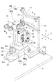
以下、本発明に係る実施形態を図面に基づき説明する。ここでは眼科装置として細隙鏡顕微鏡(以下、スリットランプと記す)を例に挙げて説明する。図1は、スリットランプの外観の説明図である。図2は、スリットランプの光学系の説明図である。図3は、図1のスリットランプを軸A−Aで切断して見たときの断面図である。図4は本体100bの内部構成の斜視図である。
Embodiments according to the present invention will be described below with reference to the drawings. Here, a slit mirror microscope (hereinafter referred to as a slit lamp) will be described as an example of an ophthalmologic apparatus. FIG. 1 is an explanatory view of the appearance of a slit lamp. FIG. 2 is an explanatory diagram of the optical system of the slit lamp. FIG. 3 is a cross-sectional view of the slit lamp of FIG. 1 as viewed by cutting along the axis AA. FIG. 4 is a perspective view of the internal configuration of the
スリットランプ100は、顔支持ユニット100aと本体100bに大別される。被検者側に設けられた顔支持ユニット100aは、被検者の額を支持する額当て11と、顎を支持する顎台12を持ち、2本の支柱13を介してテーブル1に固定されている。本体100bは、テーブル1に対して上下方向の高さ位置が調整される可動部200bと、可動部200bを支持する固定部200aを持つ。可動部200bの筐体内には、照明ユニット60、顕微鏡ユニット(観察・撮影ユニット)70、スリットランプ100全体の動作制御をする制御部85が設けられる。固定部200aの筐体内には、眼Eに対して可動部200bを上下移動させるための上下移動機構200が設けられる。
The
照明ユニット60は、可視光源61、コンデンサレンズ62、可変アパーチャ63、可変スリット64、投影レンズ65、プリズムミラー66を備え、被検者眼Eの観察部位を照明する。光源61からの光束(可視光)は、コンデンサレンズ62を透過して可変アパーチャ63及び可変スリット64を照明する。アパーチャ63及びスリット64を通過した光束は、投影レンズ65を透過してプリズムミラー66で反射され、眼Eに投射される。なお可視光源61には、ハロゲンランプ、LED等周知のものが使用される。
The
照明ユニット60のスリット64と投影レンズ65の間には、ブルーフィルタ(青色の透過フィルタ)90が挿脱可能に設けられる。ブルーフィルタ90には、例えば470〜500nmの可視の青色を透過するものが使用される。特定の波長帯域(青色)を透過するフィルタが使用されることで、励起光により患部が強調された画像が取得される。また、ブルーフィルタ90が光路中に挿入されたとき、フィルタ90の挿入を検知可能な位置には、位置センサー91が設けられる。例えば、センサー91にはフォトインタラプタ等の光学素子、スイッチ等の周知の位置検出素子が用いられる。なお、ブルーフィルタ90は照明光学系の光路中に配置されれば良く、光路中の図2に示される位置以外に配置されても良い。
A blue filter (blue transmission filter) 90 is detachably provided between the
顕微鏡ユニット70は、対物レンズ71、変倍光学系72、ハーフミラー73、結像レンズ74、正立プリズム75、視野絞り76、接眼レンズ77を持つ。眼Eで反射された光束は、対物レンズ71、変倍光学系72、ハーフミラー73、結像レンズ74を透過して、正立プリズム75で反射される。プリズム75で反射された光束は、視野絞り76、接眼レンズ77を透過して、検者の眼Fに入射する。
The
ハーフミラー73で反射された光束は、リレーレンズ78を透過してカメラ(撮像素子)80に入射する。なお撮像素子80には、可視光に感度を持つCCDを備えた周知のデジタルカメラ等が使用される。制御部85は後述するスイッチ22aからの指令信号に基づき撮像素子80の撮影画像を取り込み、モニタ87に表示させる。
The light beam reflected by the
固定部200aの上下移動機構200は、テーブル1に固定されたベース21と、ベース21に対してスライド可能に設けられた筐体21aと、筐体21a内に設置されその一部が筐体21aの図示を略す開口を介して外側に現れる操作部材であるジョイスティック22と、筐体21a内に設置された駆動部50を備える。
The up-and-down
ジョイスティック22は、検者に把持されて回転操作されるグリップ(回転部)22aと、撮影(画像取得)のトリガ信号を入力するスイッチ22bと、ジョイスティック22を略鉛直方向(Y方向)に挿通するシャフト(支持部材)22cと、グリップ22aの回転角度を検知する周知のロータリーエンコーダ22dから構成される。
The
駆動部50は、筐体21aに固定され、回転軸L1を中心として回転可能に設けられた中空のブラシレスモータ(以下、モータと記す)51と、モータ51の回転を検知する駆動検出部であるセンサー56を持つ。中空のブラシレスモータ51の中空部には、雌ネジ51bが所定のピッチに形成されており、雌ネジ51bは、後述する可動部200b側の軸52(雄ネジ52a)と結合されている。モータ51の回転に伴って雌ネジ51bが回転すると、軸52(雄ネジ52a)が雌ネジ51bを介して垂直(上下)方向に移動される。そして、雄ネジ52aの上下動に連動して可動部200bの上下方向の高さが変えられる。
The
可動部200bは、ベース21に対して略鉛直に延びるベースシャフト23と、照明ユニット60を支持するアーム24と、顕微鏡ユニット70を支持するアーム25を備える。なおアーム24とアーム25は中心軸Bを中心に個々に水平方向に回転可能に支持されており、これにより照明ユニット60と顕微鏡ユニット70が中心軸Bを中心に個別に回転される。
The movable part 200 b includes a
また可動部200bの下側には、モータ51の雌ネジ51bに挿通される軸52が固定される。軸52の先端には、所定のピッチを持つ送りネジ(雄ネジ)52aが形成され、雌ネジ51bに嵌合される。雌ネジ51bの回転が雄ネジ52aに伝達されることで、可動部200bが所定のステップで上下に移動される。
A
なお雄ネジ52aは、可動部200bが移動範囲の上限又は下限に達したときに、雌ネジ51bから外れないように、軸52上の所定範囲に形成されていれば良い。
The male screw 52a only needs to be formed in a predetermined range on the
なお雌ネジ51b及び雄ネジ52aのリード角は、可動部100bの上下動が停止された時に、可動部200bが自重で押し下げられず、位置を保持する摩擦力を奏する幅に形成される。またリード角は、可動部200bの最小の上下可動幅を考慮して決定される。つまりリード角が狭いとより細かいステップで可動部200bの上下位置合わせが行われる。一方でリード角が狭くなると、可動部200bの上下動に時間が掛かるデメリットが生じる。以上の条件を考慮してリード角が決定されれば良い。更に、雌ネジ51b及び雄ネジ52aのリード角は、材質やグリスの状態等を考慮して決定されることが好ましい。
Note that the lead angles of the
また本実施形態では、本体部100aに、可動部200bの上下動を安定させるための支持部が設けられている。例えば支持部は、固定部200aに固定された円筒部231と、円筒部231の内部に形成された中空を相通する軸232であって、可動部200b側に固定される軸232との組み合わせで構成される。
Further, in the present embodiment, the
可動部200bが上下動すると、可動部200bに固定された軸232が、円筒部231の内壁に沿って上下方向に移動する。これにより、可動部200bが複数の支持部材で保持される状態となり、上下動の動作がより安定する。
When the movable portion 200b moves up and down, the
更に本実施形態では、本体部100aに、固定部200aに対する可動部200bの上下位置を検知するための位置検出部が設けられている。例えば、位置検出部は、可動部200b側に固定されて可動部200bと連動して上下移動される板部54と、固定部200a側に固定され板部54が通過する開口を持つ3つのセンサー55a〜55cとから構成される。
Further, in the present embodiment, the
可動部200bが上下動され、板部54が3つのセンサー55a〜55c全てによって検知されると、制御部85によって可動部200bが下限に有ることが検知される。板部54がセンサー55aのみで検知されると可動部200bが上限にあることが検知される。また本実施形態では、板部54がセンサー55a及び55bで検知され、センサー55cで検知されない場合は、本体部100aが可動範囲の中間位置(図示を略すアイレベルマーカの位置)にあるとする。
When the movable portion 200b is moved up and down and the
つまり本体部100aの初期位置合わせのために、図示なきスイッチが押されると、モータ50の駆動により、板部54がセンサー55a及び55bで検知されるまで可動部200bが上下動され、初期位置が自動的に簡単に合わせられる。
なおセンサーには、フォトインタラプタ等の光センサー、磁気センサー、機械式センサー等の周知のセンサーが用いられる。
That is, when a switch (not shown) is pressed for initial alignment of the
As the sensor, a known sensor such as an optical sensor such as a photo interrupter, a magnetic sensor, or a mechanical sensor is used.
以上の構成により、検者の操作でジョイスティック22が水平方向(前後左右方向)にスライドされると、周知のスライド機構によって、眼Eに対して本体100bが水平方向に移動する。一方、グリップ22aがシャフト22bを軸として水平方向に回転されると、エンコーダ22dによってその回転方向及び回転速度等が検知される。制御部85はエンコーダ22dからの出力信号に基づき、後述するメモリ81に記憶されたグリップ22dの回転量とモータ51(ロータ57)の回転量の対応関係に基づき、モータ51(ロータ57)の回転を制御する。制御部85の駆動制御でロータ57が回転すると、中空部51aに形成された雌ネジ51bに沿って雄ネジ52aが上下移動され、可動部200b全体が上下に移動される。
With the above configuration, when the
制御部85は装置全体の駆動制御をする。制御部85には上述のグリップ22a、スイッチ22b、エンコーダ22d、センサー55a〜55c、モータ51、センサー56、モニタ87、センサー91の他、メモリ81等が接続される。
The
制御部85は、ジョイスティック22からの入力信号に基づき直接モータ51の回転量及び回転方向を制御する。また制御部85はセンサー56で検知されたモータ51の回転量や回転速度に基づき、モータ51の回転状態を検知して、ジョイスティック22からの入力信号に基づき正しく動作させる制御をする。
The
また制御部85は、センサー91からの信号に応じて、フィルタ90が照明ユニット60の光路中に配置されたことを認識する。また制御部85はフィルタ90が検知された時に、撮影モードに切換えられたとして、撮像素子80のゲインを調整する。ここでは、通常撮影モードから蛍光撮影モードに切換えられたと認識される。
Further, the
通常のフィルタを介さない撮影では、眼Eは広い波長帯域を持つ照明光で照明される。一方、フィルタを介した撮影では、照明光の波長帯域が制限されてしまい、光量不足となり鮮明な画像を得ることが困難になる場合がある。そこで従来技術では、フィルタを介した撮影では照明光量を増加させて、光量を確保する方法が提案されている。しかし、通常のフィルタは波長帯域の中心波長の透過光量を最大として、中心波長から離れるに連れて透過光量が次第に減衰する特性を持つ。その為、照明光量を増加させると、撮影に必要とされる波長帯域を持つ光束以外の、ノイズ成分の光束も増加されることになり、撮影画像を鮮明に得ることには繋がらない。 In photographing without passing through a normal filter, the eye E is illuminated with illumination light having a wide wavelength band. On the other hand, in the case of photographing through a filter, the wavelength band of illumination light is limited, and the amount of light is insufficient, and it may be difficult to obtain a clear image. In view of this, the prior art has proposed a method for increasing the amount of illumination light to ensure the amount of light in photographing through a filter. However, a normal filter has a characteristic that the transmitted light amount at the center wavelength in the wavelength band is maximized and the transmitted light amount is gradually attenuated as the distance from the center wavelength increases. For this reason, when the amount of illumination light is increased, the light flux of noise components other than the light flux having the wavelength band required for photographing is also increased, and the photographed image is not clearly obtained.
一方、撮影条件に応じて、検者が撮像素子の画素のゲインをマニュアルで調節する方法も考えられるが、撮影条件の変更の都度、設定をし直す必要があり、検者にとって手間が掛かることが負担になる。また、撮像素子の画素のゲイン設定のし忘れがあると、撮影の失敗に繋がるおそれが有る。同様に、撮像素子で取得された撮影画像の画質を、パソコン等の画像処理装置を用いて調整することも考えられるが、この場合も検者の手間となる。 On the other hand, there may be a method in which the examiner manually adjusts the gain of the pixel of the image sensor according to the photographing conditions, but it is necessary to reset the setting every time the photographing conditions are changed, which takes time and effort for the examiner. Is a burden. In addition, if there is a mistake in setting the gain of the pixel of the image sensor, there is a risk of failure of shooting. Similarly, it is conceivable to adjust the image quality of the captured image acquired by the image sensor using an image processing apparatus such as a personal computer.
そこで本発明は、フィルタを介して撮影を行う際に、フィルタを透過した波長帯域の光束に対応する波長帯域(色)の撮像素子の画素のゲインを増加させる。又はフィルタを透過した波長帯域の光束による励起光に対応する波長帯域(色)の撮像素子の画素のゲインを増加させる。一方、フィルタで遮光される波長帯域の光束に対応する波長帯域(色)の撮像素子の画素のゲインを減少させる。又は、励起光の波長帯域(色)以外の波長帯域(色)に対応する撮像素子の画素のゲインを減少させる。 Therefore, the present invention increases the gain of the pixel of the imaging element in the wavelength band (color) corresponding to the light flux in the wavelength band that has passed through the filter when shooting through the filter. Alternatively, the gain of the pixel of the imaging element in the wavelength band (color) corresponding to the excitation light by the light flux in the wavelength band that has passed through the filter is increased. On the other hand, the gain of the pixel of the imaging device in the wavelength band (color) corresponding to the light flux in the wavelength band shielded by the filter is reduced. Alternatively, the gain of the pixel of the image sensor corresponding to a wavelength band (color) other than the wavelength band (color) of the excitation light is decreased.
つまり、ここではフィルタ90の青色光束によって励起される緑色の波長帯域の光束に対応する緑色の画素80bのゲインが増加され、赤色の画素80aと青色の画素80cのゲインを減少させるようにゲイン調整がされる。このようにすると、ノイズ光を抑え、フィルタの透過特性に応じた撮影画像を得ることができる。またフィルタ検知で、自動的に撮像素子のゲイン調整がされることで、検者の設定の手間を省き、撮影不備の発生を抑えることができる。
That is, the gain adjustment is performed so that the gain of the green pixel 80b corresponding to the light beam in the green wavelength band excited by the blue light beam of the
またパソコン上で行われるゲイン補正や色補正は、予め撮像素子で取得されたノイズ成分が含まれる画像を対象とするのに対して、本発明は撮像素子による画像の取得時に、ゲイン及び色補正が行われる。そのため、予めノイズ成分が取り除かれた画像が取得されるので、パソコン等による補正と比べて画質が向上される。 In addition, while gain correction and color correction performed on a personal computer target an image including a noise component acquired in advance by an image sensor, the present invention performs gain and color correction when acquiring an image by the image sensor. Is done. Therefore, an image from which noise components have been removed in advance is acquired, so that the image quality is improved as compared with correction by a personal computer or the like.
次に、以上のような細隙鏡顕微鏡を用いて、フィルタを設置した状態で被検者眼の撮影を行う場合の動作を説明する。まず、本体100bの図示を略すスリットからフィルタ90が挿入され、患者眼に点眼剤(蛍光剤)が点眼される。制御部85によってセンサー91の検知信号が検知されると、蛍光撮影モードが認識される。制御部85は、撮像素子80のゲインを調節する。ここでは、緑色の画素80bのゲインが高く設定され、赤色の画素80aと青色の画素80cのゲインが低く設定される。
Next, using the slit mirror microscope as described above, an operation in the case of photographing the subject's eye with the filter installed will be described. First, the
撮影準備が完了して、光源61が点灯されると、光源61からの光束が、コンデンサレンズ62から投影レンズ65を経て、フィルタ90に入射される。フィルタ90は光源61から照射された光束のうち、青色の所定帯域の波長成分のみを透過させる。フィルタ90を透過した青色成分の光束は、プリズムミラー66を経て、被検者眼Eを照明する。蛍光剤を点眼された被検者眼Eからの緑色の励起光は、対物レンズ71を経てハーフミラー73で反射される。その反射光は、リレーレンズ78を経て撮像素子80で撮像される。
When the preparation for photographing is completed and the
この時、撮像素子80の緑色の画素80bのゲインのみが増加されるので、緑色(蛍光)の撮影画像がより鮮明な状態で取得される。撮像素子38で取得された画像はメモリ81に記憶される。この時、センサー91の検知信号に基づくフィルタ90の使用情報も共に記憶されるとする。
なお照明ユニット60の光路から、フィルタ90が取り除かれると、センサー91からの検知信号に応じて、制御部85は撮影モードが通常撮影に戻されたと認識して、撮像素子80のゲイン調整を戻す処理をする。
At this time, since only the gain of the green pixel 80b of the
When the
なお、撮像素子80のゲイン調整と共に、光源61の照明光量が増加されても良い。本発明では、フィルタを透過した波長帯域の、撮像素子80の画素のゲインのみが増加されるので、ノイズ光の影響を抑えつつ、より鮮明な画像を得ることができる。
In addition, the illumination light quantity of the
なおメモリ81に記憶された撮影画像は、撮影情報と共に出力される。例えば、図示を略す外部記憶媒体やLAN等を介して、メモリ81の撮影画像と、センサー91での検知結果に基づくフィルタの使用情報が外部出力される。この場合、撮影画像83に蛍光撮影の情報が付与されるようになり、検者による撮影画像の管理が容易になる。例えば、フィルタの使用情報として、撮影において青色フィルタが使用されたことを示す情報、青色フィルタを用いて撮影された撮影画像であることを示す情報が挙げられ、撮影画像ともに出力される。なお、パソコンを介して電子カルテ上に出力される場合には、撮影画像と、フィルタの使用情報とが所定の表示欄に簡単に表示される。また電子カルテによる撮影情報の集計がより正確に行われるようになり、検者の使い勝手が向上される。
Note that the photographed image stored in the memory 81 is output together with the photographing information. For example, the captured image of the memory 81 and the use information of the filter based on the detection result of the
なお上記では、蛍光、染色反応観察等に使用される青色のフィルタを用いる例を示した。これ以外にも、細隙鏡顕微鏡に使用される様々な種類のフィルタに対して、本発明の構成が適用されることで、撮像素子を容易に撮影に適した設定にでき、鮮明な画像を取得できるようになる。例えば、照明光学系の光路には、視神経繊維の異常を検査する際に使用する無赤色フィルタ(グリーンフィルタ)等が配置される。観察・撮影光学系の光路には、ブルーフィルタとの組み合わせにより、励起用ブルーの光を抑え、蛍光像を更に見やすくするためのイエローフィルタ等が配置される。 In the above, an example using a blue filter used for fluorescence, staining reaction observation, etc. has been shown. In addition to this, the configuration of the present invention is applied to various types of filters used in the slit microscope, so that the image sensor can be easily set to be suitable for photographing, and a clear image can be obtained. You can get it. For example, in the optical path of the illumination optical system, a non-red filter (green filter) used for inspecting abnormalities of the optic nerve fiber is disposed. In the optical path of the observation / photographing optical system, a yellow filter or the like for suppressing the blue light for excitation by combining with a blue filter and making the fluorescent image easier to see is disposed.
なお、フィルタが複数配置されている場合、検知部は、フィルタの有無の他、どのフィルタが光路中に配置され撮影に使用されたかを判別できることが好ましい。この場合、撮影画像と、どのフィルタが使用されたかを含むフィルタ使用情報が外部出力される。なお、複数のフィルタから1つのフィルタを判別する場合、例えば、複数のフィルタが配置された回転ディスクの位置を検出することにより、フィルタの種類を判別できる。 When a plurality of filters are arranged, it is preferable that the detection unit can determine which filter is arranged in the optical path and used for photographing in addition to the presence or absence of the filter. In this case, the captured image and filter usage information including which filter is used are output to the outside. When determining one filter from a plurality of filters, for example, the type of the filter can be determined by detecting the position of the rotating disk on which the plurality of filters are arranged.
以上のような制御が行われることで、ノイズ光の影響が抑制された鮮明な画像を得ることができる。また撮影画像と共にフィルタ検知の情報が出力されることで、撮影画像の管理等が容易になる。更には、顕微鏡ユニット70を介した肉眼観察では見逃してしまいそうな弱い(小さい)蛍光部分であったとしても、撮像素子80で取得された画像のゲインが適切に調節され、パソコン等のモニタ上に強調表示されることで、病態をより正確に把握の手助けとなる。
By performing the control as described above, it is possible to obtain a clear image in which the influence of noise light is suppressed. In addition, the filter detection information is output together with the captured image, thereby facilitating management of the captured image. Furthermore, even if it is a weak (small) fluorescent portion that is likely to be overlooked by the naked eye observation through the
なおエキサイタフィルタとバリアフィルタの組み合わせ等、一度の撮影に複数のフィルタが用いられる場合には、少なくとも一方のフィルタの検知結果に基づいて、撮像素子のゲイン調整が行われれば良い。 When a plurality of filters are used for one shooting, such as a combination of an exciter filter and a barrier filter, the gain adjustment of the image sensor may be performed based on the detection result of at least one filter.
なお上記の構成では、フィルタ90の挿入を検知するための位置センサー91を設ける例を示した。これ以外にもフィルタ90の挿入は、撮像素子80の撮影画像に基づき検知されても良い。つまり、各フィルタ90挿入時の撮像素子80の画素の輝度分布の特徴を予めメモリ81に記憶させておき、位置センサー91を設けずに撮像素子80からの情報によって各種フィルタの配置が検知されるようにしても良い。
In the above configuration, the example in which the
60 照明ユニット
70 顕微鏡ユニット
90 フィルタ
91 センサー
80 撮像素子
80a 赤色の画素
80b 緑色の画素
80c 青色の画素
85 制御部
100 スリットランプ
60
Claims (6)
該照明光源で照明された被検者眼を観察する観察光学系と、
前記照明光源で照明された被検者眼を撮影する撮像素子を持つ撮影光学系と、
を備える細隙鏡顕微鏡において、
前記照明光学系又は前記撮影光学系の光路中に挿脱可能に設けられるフィルタと、
前記光路中に置かれたフィルタを検知するフィルタ検知部と、
該フィルタ検知部による前記フィルタの検知信号に応じて、前記撮像素子の各画素から出力される信号のゲインを調整するゲイン調整手段と、を備えることを特徴とする細隙鏡顕微鏡。 An illumination optical system having an illumination light source for illuminating the subject's eye;
An observation optical system for observing the eye of the subject illuminated by the illumination light source;
An imaging optical system having an image sensor for imaging the eye of the subject illuminated by the illumination light source;
In a slit mirror microscope comprising:
A filter that is detachably provided in an optical path of the illumination optical system or the photographing optical system;
A filter detection unit for detecting a filter placed in the optical path;
A slit mirror microscope comprising: a gain adjusting unit that adjusts a gain of a signal output from each pixel of the image pickup device in accordance with a detection signal of the filter by the filter detection unit.
前記ゲイン補正手段は、前記撮像素子の緑色の画素から出力される信号のゲインを増幅させ、赤色と青色の画素から出力される信号のゲインを減少させる補正をする請求項2に記載の細隙鏡顕微鏡。 The filter is a blue filter that transmits visible blue color,
3. The slit according to claim 2, wherein the gain correction unit performs correction to amplify a gain of a signal output from a green pixel of the image sensor and reduce a gain of a signal output from a red pixel and a blue pixel. Mirror microscope.
該出力手段は、前記フィルタ検知部での検知信号に基づく前記フィルタの使用情報を、前記撮像素子で撮像された画像と共に出力させる請求項1〜3のいずれかに記載の細隙鏡顕微鏡。 Output means for outputting information of the eye of the subject imaged by the imaging element;
The slit mirror microscope according to any one of claims 1 to 3, wherein the output unit outputs use information of the filter based on a detection signal from the filter detection unit together with an image captured by the image sensor.
The gain adjusting means amplifies the gain of the signal output from the pixel corresponding to the wavelength band of the light beam transmitted through the filter, and the gain of the signal output from the pixel corresponding to the wavelength band shielded by the filter The slit mirror microscope according to claim 1, wherein
Priority Applications (1)
| Application Number | Priority Date | Filing Date | Title |
|---|---|---|---|
| JP2012149697A JP2014012036A (en) | 2012-07-03 | 2012-07-03 | Slit lamp microscope |
Applications Claiming Priority (1)
| Application Number | Priority Date | Filing Date | Title |
|---|---|---|---|
| JP2012149697A JP2014012036A (en) | 2012-07-03 | 2012-07-03 | Slit lamp microscope |
Publications (2)
| Publication Number | Publication Date |
|---|---|
| JP2014012036A true JP2014012036A (en) | 2014-01-23 |
| JP2014012036A5 JP2014012036A5 (en) | 2015-08-13 |
Family
ID=50108205
Family Applications (1)
| Application Number | Title | Priority Date | Filing Date |
|---|---|---|---|
| JP2012149697A Pending JP2014012036A (en) | 2012-07-03 | 2012-07-03 | Slit lamp microscope |
Country Status (1)
| Country | Link |
|---|---|
| JP (1) | JP2014012036A (en) |
Cited By (3)
| Publication number | Priority date | Publication date | Assignee | Title |
|---|---|---|---|---|
| JP2016140636A (en) * | 2015-02-04 | 2016-08-08 | 株式会社ニデック | Ophthalmologic apparatus, ophthalmologic system and ophthalmologic photographing program |
| JP2016209453A (en) * | 2015-05-13 | 2016-12-15 | 株式会社トプコン | Slit lamp microscope |
| JP2017099719A (en) * | 2015-12-02 | 2017-06-08 | 株式会社ニデック | Slit-lamp microscope |
Citations (9)
| Publication number | Priority date | Publication date | Assignee | Title |
|---|---|---|---|---|
| JPH05329107A (en) * | 1992-06-03 | 1993-12-14 | Topcon Corp | Ophthalmologic camera apparatus |
| JPH0626803U (en) * | 1992-09-04 | 1994-04-12 | 株式会社ニコン | Ophthalmic imaging device |
| JPH0698859A (en) * | 1992-08-04 | 1994-04-12 | Topcon Corp | Ophthalmic image processing system |
| JPH07213511A (en) * | 1994-02-03 | 1995-08-15 | Miki:Kk | Personal identification device |
| JP2004112411A (en) * | 2002-09-19 | 2004-04-08 | Ikegami Tsushinki Co Ltd | Medical television camera instrument and ophthalmological photographing equipment using it |
| JP2006006653A (en) * | 2004-06-25 | 2006-01-12 | Topcon Corp | Fundus photographing system |
| JP2010259532A (en) * | 2009-04-30 | 2010-11-18 | Canon Inc | Ophthalmologic observation and photographing apparatus |
| JP2010274048A (en) * | 2009-06-01 | 2010-12-09 | Canon Inc | Fundus camera |
| JP2011177273A (en) * | 2010-02-26 | 2011-09-15 | Nidek Co Ltd | Slit-lamp microscope |
-
2012
- 2012-07-03 JP JP2012149697A patent/JP2014012036A/en active Pending
Patent Citations (9)
| Publication number | Priority date | Publication date | Assignee | Title |
|---|---|---|---|---|
| JPH05329107A (en) * | 1992-06-03 | 1993-12-14 | Topcon Corp | Ophthalmologic camera apparatus |
| JPH0698859A (en) * | 1992-08-04 | 1994-04-12 | Topcon Corp | Ophthalmic image processing system |
| JPH0626803U (en) * | 1992-09-04 | 1994-04-12 | 株式会社ニコン | Ophthalmic imaging device |
| JPH07213511A (en) * | 1994-02-03 | 1995-08-15 | Miki:Kk | Personal identification device |
| JP2004112411A (en) * | 2002-09-19 | 2004-04-08 | Ikegami Tsushinki Co Ltd | Medical television camera instrument and ophthalmological photographing equipment using it |
| JP2006006653A (en) * | 2004-06-25 | 2006-01-12 | Topcon Corp | Fundus photographing system |
| JP2010259532A (en) * | 2009-04-30 | 2010-11-18 | Canon Inc | Ophthalmologic observation and photographing apparatus |
| JP2010274048A (en) * | 2009-06-01 | 2010-12-09 | Canon Inc | Fundus camera |
| JP2011177273A (en) * | 2010-02-26 | 2011-09-15 | Nidek Co Ltd | Slit-lamp microscope |
Cited By (3)
| Publication number | Priority date | Publication date | Assignee | Title |
|---|---|---|---|---|
| JP2016140636A (en) * | 2015-02-04 | 2016-08-08 | 株式会社ニデック | Ophthalmologic apparatus, ophthalmologic system and ophthalmologic photographing program |
| JP2016209453A (en) * | 2015-05-13 | 2016-12-15 | 株式会社トプコン | Slit lamp microscope |
| JP2017099719A (en) * | 2015-12-02 | 2017-06-08 | 株式会社ニデック | Slit-lamp microscope |
Similar Documents
| Publication | Publication Date | Title |
|---|---|---|
| US10117573B2 (en) | Fundus photography device | |
| JP5850349B2 (en) | Ophthalmic imaging equipment | |
| JP2011045553A (en) | Fundus imaging apparatus | |
| JP2020006172A (en) | Ocular fundus imaging apparatus | |
| JP2015066242A (en) | Ophthalmology imaging apparatus | |
| JP6531369B2 (en) | Fundus imaging device | |
| JP2014012036A (en) | Slit lamp microscope | |
| JP5466055B2 (en) | Fundus camera | |
| JP2006180926A (en) | Medical display device | |
| JP6319616B2 (en) | Scanning laser ophthalmoscope | |
| JP4542350B2 (en) | Anterior eye measurement device | |
| JP2009247772A (en) | Fundus camera | |
| JP6631009B2 (en) | Ophthalmic apparatus, ophthalmic system, and ophthalmic imaging program | |
| CN103799964A (en) | Ophthalmologic apparatus and ophthalmologic imaging method | |
| WO2016136859A1 (en) | Ocular fundus imaging system | |
| JP7200516B2 (en) | Fundus camera | |
| JP5484505B2 (en) | Ophthalmic imaging equipment | |
| JP5438119B2 (en) | Ophthalmic measuring device | |
| JP3870211B2 (en) | Fundus camera | |
| JP5050128B2 (en) | Image processing apparatus and method | |
| JP2009207572A (en) | Fundus camera | |
| JP7355194B2 (en) | fundus imaging device | |
| JP7375323B2 (en) | fundus imaging device | |
| JP6207209B2 (en) | Ophthalmic apparatus, control method for ophthalmic apparatus, and program | |
| US8764190B2 (en) | Fundus camera |
Legal Events
| Date | Code | Title | Description |
|---|---|---|---|
| A521 | Request for written amendment filed |
Free format text: JAPANESE INTERMEDIATE CODE: A523 Effective date: 20150626 |
|
| A621 | Written request for application examination |
Free format text: JAPANESE INTERMEDIATE CODE: A621 Effective date: 20150626 |
|
| A977 | Report on retrieval |
Free format text: JAPANESE INTERMEDIATE CODE: A971007 Effective date: 20160425 |
|
| A131 | Notification of reasons for refusal |
Free format text: JAPANESE INTERMEDIATE CODE: A131 Effective date: 20160506 |
|
| A521 | Request for written amendment filed |
Free format text: JAPANESE INTERMEDIATE CODE: A523 Effective date: 20160705 |
|
| A131 | Notification of reasons for refusal |
Free format text: JAPANESE INTERMEDIATE CODE: A131 Effective date: 20161011 |
|
| A02 | Decision of refusal |
Free format text: JAPANESE INTERMEDIATE CODE: A02 Effective date: 20170418 |