JP2014009089A - Low temperature storage system - Google Patents
Low temperature storage system Download PDFInfo
- Publication number
- JP2014009089A JP2014009089A JP2012148790A JP2012148790A JP2014009089A JP 2014009089 A JP2014009089 A JP 2014009089A JP 2012148790 A JP2012148790 A JP 2012148790A JP 2012148790 A JP2012148790 A JP 2012148790A JP 2014009089 A JP2014009089 A JP 2014009089A
- Authority
- JP
- Japan
- Prior art keywords
- storage
- plate
- low
- chamber
- low temperature
- Prior art date
- Legal status (The legal status is an assumption and is not a legal conclusion. Google has not performed a legal analysis and makes no representation as to the accuracy of the status listed.)
- Granted
Links
Images


Landscapes
- Warehouses Or Storage Devices (AREA)
- Devices That Are Associated With Refrigeration Equipment (AREA)
Abstract
Description
本発明は、試料を収容する容器を低温で保管する低温保管システムに関し、特に、創薬(drug discovery)、すなわち、医学、生物工学および薬学において薬剤を発見したり設計したりするプロセスにおいて用いられる創薬用試料を超低温で保管するために使用される低温保管システムに関する。 The present invention relates to a cryogenic storage system for storing a container containing a sample at a low temperature, and particularly used in drug discovery, that is, a process for discovering and designing a drug in medicine, biotechnology and pharmacy. The present invention relates to a cryogenic storage system used for storing a drug discovery sample at an ultra-low temperature.
創薬研究の分野においては、大量の試料を低温で保管したり分析したりする実験を高効率で行う必要がある。
このため、低温保管すべき試料を収容する複数の容器をそれぞれ保持する複数の保管プレートを保管ラックに鉛直方向に重ねて収容し、必要に応じて目的の保管プレートから個別且つ自動的に容器を取り出す低温保管システムが提案されている(例えば、特許文献1参照)。
In the field of drug discovery research, it is necessary to conduct experiments for storing and analyzing large quantities of samples at low temperatures with high efficiency.
For this reason, a plurality of storage plates, each holding a plurality of containers for storing samples to be stored at low temperatures, are vertically stacked on the storage rack and stored individually and automatically from the target storage plate as necessary. A low-temperature storage system for taking out has been proposed (see, for example, Patent Document 1).
上述の低温保管システムは、複数の保管プレートを鉛直方向に重ねて収容する複数の保管ラックと、これら複数の保管ラックを格納する低温格納室と、低温格納室の上方に隣接して設けられた作業室と、作業室内に設けられ保管プレートを搬送するとともに保管ラックに出し入れするプレート搬送機構と、作業室に隣接して設けられた入出庫室からプレート搬送機構によって搬送された保管プレートとプレート搬送機構によって保管ラックから取り出された保管プレートとの間で容器を個別に移載可能に構成されたピックアップ機構とを備えている。 The low-temperature storage system described above is provided with a plurality of storage racks that accommodate a plurality of storage plates stacked in the vertical direction, a low-temperature storage chamber that stores the plurality of storage racks, and an upper side of the low-temperature storage chamber. A working chamber, a plate conveying mechanism that is provided in the working chamber and conveys the storage plate and puts it in and out of the storage rack, and a storage plate and a plate conveyance that are conveyed by the plate conveying mechanism from an input / output chamber provided adjacent to the working chamber. And a pickup mechanism configured to be able to individually transfer containers to and from the storage plate taken out from the storage rack by the mechanism.
しかしながら、上述の低温保管システムでは、作業室の温度が低温格納室の温度ほど低くないため、保管ラックから保管プレートを取り出した後、この保管プレートに保持されている容器や保管プレートから取り出された容器が低温格納室の温度より高い温度に曝露され、これら容器内の試料に温度上昇が生じてしまうという問題点があった。 However, in the above-described low-temperature storage system, the temperature of the working chamber is not as low as the temperature of the low-temperature storage chamber, so after the storage plate is taken out from the storage rack, it is taken out from the container or storage plate held on this storage plate. There was a problem that the containers were exposed to a temperature higher than the temperature of the cold storage chamber, and the temperature in the samples in these containers increased.
また、低温格納室を超低温状態とし、外部環境に曝される時間を短期間とすることで容器内の試料に与える影響を少なくすることも考えられるが、超低温とするほど短時間でも保管プレートや容器に大量の結露や霜が発生するという問題点があった。 In addition, it is possible to reduce the effect on the sample in the container by setting the cryogenic storage chamber to an ultra-low temperature state and reducing the exposure time to the external environment for a short period of time. There was a problem that a large amount of dew condensation and frost were generated in the container.
そこで、本発明が解決しようとする技術的課題、すなわち、本発明の目的は、保管ラックから保管プレートを取り出した後、少なくともこの保管プレートに保持された容器に収容されている試料の温度上昇を抑制するとともに低露点環境を実現して容器や保管プレートに生じがちな結露や霜を防ぐ低温保管システムを提供することである。 Therefore, the technical problem to be solved by the present invention, that is, the object of the present invention is to increase the temperature of the sample contained in at least the container held on the storage plate after taking out the storage plate from the storage rack. Another object of the present invention is to provide a low-temperature storage system that suppresses condensation and frost that tend to occur on containers and storage plates while realizing a low dew point environment.
本請求項1に係る発明は、複数の容器をそれぞれ保持する複数の保管プレートを鉛直方向にそれぞれ収容する複数の保管ラックと、該複数の保管ラックを格納する低温格納室と、該低温格納室に隣接して設けられた作業室と、該作業室内に設けられ前記保管プレートを搬送するとともに前記保管ラックに出し入れするプレート搬送機構と、前記容器を個別に取り出し可能に構成されたピックアップ機構とを備えている低温保管システムであって、前記保管プレートを収容する低温収容槽が、前記プレート搬送機構に付設されていることにより、前述した課題を解決したものである。 According to the first aspect of the present invention, there are provided a plurality of storage racks that respectively accommodate a plurality of storage plates that respectively hold a plurality of containers in the vertical direction, a low-temperature storage chamber that stores the plurality of storage racks, and the low-temperature storage chamber A work chamber provided adjacent to the work chamber, a plate transport mechanism that is provided in the work chamber and transports the storage plate and puts it in and out of the storage rack, and a pickup mechanism configured to be able to take out the containers individually. In the low-temperature storage system provided, a low-temperature storage tank that stores the storage plate is attached to the plate transport mechanism, thereby solving the above-described problems.
本請求項2に係る発明は、請求項1に係る低温保管システムの構成に加えて、前記ピックアップ機構が、前記作業室に隣接して設けられた入出庫室から前記プレート搬送機構によって搬送された保管プレートと前記プレート搬送機構によって前記保管ラックから取り出された保管プレートとの間で前記容器を前記低温収容槽内で個別に移載可能に構成された状態で前記プレート搬送機構に付設されていることにより、前述した課題を解決したものである。 In the invention according to claim 2, in addition to the configuration of the low-temperature storage system according to claim 1, the pickup mechanism is transported by the plate transport mechanism from an input / output chamber provided adjacent to the work chamber. The container is attached to the plate transport mechanism in a state in which the container can be individually transferred in the low temperature storage tank between the storage plate and the storage plate taken out from the storage rack by the plate transport mechanism. This solves the above-mentioned problems.
本請求項3に係る発明は、請求項1又は請求項2に係る低温保管システムの構成に加えて、前記プレート搬送機構が、前記保管ラックを低温格納室から作業室に個別に昇降自在に出し入れする保管ラック昇降手段と、前記保管ラックから前記保管プレートを個別に出し入れする保管プレート引出手段と、前記保管ラック昇降手段及び保管プレート引出手段を設置した状態で作業室内を移動可能に構成された搬送用移動手段とを有していることにより、前述した課題をさらに解決したものである。 According to the third aspect of the present invention, in addition to the configuration of the low temperature storage system according to the first or second aspect, the plate transport mechanism is configured to allow the storage rack to be moved up and down individually from the low temperature storage chamber to the work chamber. Storage rack lifting and lowering means, storage plate pulling means for individually taking in and out the storage plate from the storage rack, and transport configured to be movable in the work chamber in a state where the storage rack lifting and lowering means and the storage plate pulling means are installed. The above-described problems are further solved by having the moving means.
本請求項4に係る発明は、請求項1乃至請求項3のいずれか一つに係る低温保管システムの構成に加えて、前記低温格納室が、−80℃以下の超低温環境に保たれており、前記作業室が、低湿度環境に保たれていることにより、前述した課題をさらに解決したものである。 In the invention according to claim 4, in addition to the configuration of the low temperature storage system according to any one of claims 1 to 3, the low temperature storage chamber is maintained in an ultra low temperature environment of −80 ° C. or lower. Since the working chamber is maintained in a low humidity environment, the above-described problems are further solved.
本請求項1の発明に係る低温保管システムは、複数の容器をそれぞれ保持する複数の保管プレートを鉛直方向にそれぞれ収容する複数の保管ラックと、これら複数の保管ラックを格納する低温格納室と、この低温格納室に隣接して設けられた作業室と、この作業室内に設けられて保管プレートを搬送するとともに保管ラックに出し入れするプレート搬送機構と、容器を個別に取り出し可能に構成されたピックアップ機構とを備えていることにより、保管プレートから個別且つ自動的に容器を移載することができるばかりでなく、以下のような本発明に特有の効果を奏することができるものである。
すなわち、請求項1の発明に係る低温保管システムは、保管プレートを収容する低温収容槽が、プレート搬送機構に付設されていることにより、作業室より低温の低温収容槽内に収容された保管プレートや保管プレート内における容器の温度上昇が抑制されるとともに保管プレート及び容器と作業室とに比べて保管プレート及び容器と低温収容槽との温度差が小さくなるため、容器に収容された試料の温度上昇を抑制するとともに低露点環境を実現して容器や保管プレートに生じがちな結露や霜を防ぐことができる。
A cryogenic storage system according to the invention of claim 1 includes a plurality of storage racks that respectively accommodate a plurality of storage plates that respectively hold a plurality of containers in the vertical direction, a cryogenic storage chamber that stores the plurality of storage racks, A working chamber provided adjacent to the low-temperature storage chamber, a plate conveying mechanism provided in the working chamber for conveying the storage plate and taking it in and out of the storage rack, and a pickup mechanism configured to be able to take out the containers individually In addition to being able to transfer containers individually and automatically from the storage plate, the following effects specific to the present invention can be achieved.
That is, in the low temperature storage system according to the invention of claim 1, the low temperature storage tank for storing the storage plate is attached to the plate transport mechanism, so that the storage plate stored in the low temperature storage tank at a lower temperature than the work chamber. In addition, the temperature rise of the container in the storage plate is suppressed, and the temperature difference between the storage plate, the container, and the low temperature storage tank is smaller than that of the storage plate, the container, and the working chamber. While suppressing the rise, a low dew point environment can be realized to prevent dew condensation and frost that tend to occur on containers and storage plates.
本請求項2に係る低温保管システムによれば、請求項1に係る低温保管システムが奏する効果に加えて、ピックアップ機構が、作業室に隣接して設けられた入出庫室からプレート搬送機構によって搬送された保管プレートとプレート搬送機構によって保管ラックから取り出された保管プレートとの間で容器を低温収容槽内で個別に移載可能に構成された状態でプレート搬送機構に付設されていることにより、保管プレートの搬送途中だけでなく容器の移載途中においても保管プレート及び保管プレート内の容器が作業室より低温の低温環境下にあるため、容器移載時の試料の温度上昇を抑制するとともに容器移載時に容器や保管プレートに生じがちな結露や霜を防ぐことができる。
加えて、プレート搬送機構に対してピックアップ機構を離間配置する場合に比べて、保管ラックから取り出した保管プレートをピックアップ機構まで搬送する搬送距離が短くなることで保管プレートを保管ラックから取り出して再度保管ラックに収納するまでの時間が短縮されるため、保管ラック及び保管ラックに収納された保管プレートが低温格納室から搬出されている時間を短縮して結露や霜が生じる機会すなわち時間を低減することができる。
さらに、ピックアップ機構に設けられて保管プレートを載置するプレート載置部が低温収容槽内で局所的に低温化されるため、容器移載時に低温格納室から出たばかりの容器及び保管プレートとこれらの周辺空間との温度差を増大し難くして結露や霜を防ぐことができる。
According to the low-temperature storage system according to the second aspect, in addition to the effect exhibited by the low-temperature storage system according to the first aspect, the pickup mechanism is transported by the plate transport mechanism from the loading / unloading chamber provided adjacent to the work chamber. By being attached to the plate transport mechanism in a state where the container can be individually transferred in the low temperature storage tank between the storage plate and the storage plate taken out from the storage rack by the plate transport mechanism, Since the storage plate and the container in the storage plate are in a low temperature environment lower than the work room, not only during the transfer of the storage plate but also during the transfer of the container, the temperature rise of the sample during the transfer of the container is suppressed and the container Condensation and frost that tend to occur in containers and storage plates during transfer can be prevented.
In addition, compared to the case where the pickup mechanism is spaced apart from the plate transport mechanism, the transport distance for transporting the storage plate taken out from the storage rack to the pickup mechanism is shortened, so that the storage plate is removed from the storage rack and stored again. Since the time until it is stored in the rack is shortened, the time during which the storage rack and the storage plate stored in the storage rack are carried out of the low temperature storage chamber is shortened to reduce the chance of condensation or frost, that is, the time. Can do.
Furthermore, since the plate mounting portion provided in the pickup mechanism for mounting the storage plate is locally cooled in the low temperature storage tank, the container and the storage plate that have just come out of the low temperature storage chamber when the container is transferred and these Condensation and frost can be prevented by making it difficult to increase the temperature difference from the surrounding space.
本請求項3に係る低温保管システムによれば、請求項1または請求項2に係る低温保管システムが奏する効果に加えて、プレート搬送機構が、保管ラックを低温格納室から作業室に個別に昇降自在に出し入れする保管ラック昇降手段と、保管ラックから保管プレートを個別に出し入れする保管プレート引出手段と、保管ラック昇降手段及び保管プレート引出手段を設置した状態で作業室内を移動可能に構成された搬送用移動手段とを有していることにより、低温格納室から取り出された保管プレートの上下方向及び水平方向への移動動作や作業室内での搬送動作を迅速に行うため、低温格納室から取り出された保管プレートやこの保管プレートにおける容器の温度上昇に繋がるプレート搬送時間を短縮して試料の温度上昇を抑制することができる。 According to the low temperature storage system according to the third aspect, in addition to the effect exhibited by the low temperature storage system according to the first or second aspect, the plate transport mechanism lifts the storage rack individually from the low temperature storage room to the work room. Storage rack lifting and lowering means that can be freely inserted and removed, storage plate pulling means for individually loading and unloading storage plates from the storage rack, and transport configured to be movable in the work chamber with the storage rack lifting and lowering means and the storage plate pulling means installed For moving the storage plate taken out from the low temperature storage chamber in the vertical and horizontal directions and transporting it in the work chamber quickly, so that the storage plate is taken out from the low temperature storage chamber. It is possible to suppress the temperature rise of the sample by shortening the plate transport time that leads to the temperature rise of the storage plate and the container in this storage plate. That.
本請求項4に係る低温保管システムによれば、請求項1乃至請求項3のいずれか一つに係る低温保管システムが奏する効果に加えて、低温格納室が、−80℃以下の超低温環境に保たれており、作業室が、低湿度環境に保たれていることにより、保管プレート及び保管プレートに保持された容器が−80℃以下の超低温状態で作業室内に取り出されても保管プレート及び容器の表面で凝縮する水蒸気が少ないため、容器や保管プレートに発生し得る結露や霜の発生量を容器内の試料の保存状態に悪影響を及ぼさない程度まで低減することができる。 According to the cryogenic storage system according to claim 4, in addition to the effects exhibited by the cryogenic storage system according to any one of claims 1 to 3, the cryogenic storage chamber is placed in an ultra-low temperature environment of −80 ° C. or lower. Because the work chamber is kept in a low-humidity environment, the storage plate and the container even if the container held on the storage plate is taken out into the work chamber at an extremely low temperature of −80 ° C. or lower. Since the amount of water vapor condensed on the surface of the container is small, the amount of condensation or frost that can occur in the container or the storage plate can be reduced to an extent that does not adversely affect the storage state of the sample in the container.
本発明は、複数の容器をそれぞれ保持する複数の保管プレートを鉛直方向にそれぞれ収容する複数の保管ラックと、これら複数の保管ラックを格納する低温格納室と、この低温格納室に隣接して設けられた作業室と、この作業室内に設けられて保管プレートを搬送するとともに保管ラックに出し入れするプレート搬送機構と、容器を個別に取り出し可能に構成されたピックアップ機構とを備えている低温保管システムにおいて、保管プレートを収容する低温収容槽が、プレート搬送機構に付設され、容器に収容された試料の温度上昇を抑制するとともに、低露点環境すなわち保管プレート及び容器とその周辺空間との温度差を小さくすることで結露や霜の発生を抑制する環境を実現した状態で、容器や保管プレートに生じがちな結露や霜を防ぐものであれば、その具体的な実施の態様は、いかなるものであっても何ら構わない。
また、本発明の低温保管システムでは、個別に容器を取り出せるようにシステムの動作が制御装置により制御される。
なお、以下の各実施例では、説明の便宜上複数の保管プレートを相互に区別する必要がある場合には、参照符号Bに添字1、2を付して相互に区別している。
The present invention provides a plurality of storage racks that respectively store a plurality of storage plates that respectively hold a plurality of containers in a vertical direction, a low-temperature storage chamber that stores the plurality of storage racks, and an adjacent to the low-temperature storage chamber. In a low-temperature storage system comprising: a work chamber provided; a plate transport mechanism that is provided in the work chamber and transports a storage plate and takes it in and out of a storage rack; and a pickup mechanism configured to be able to individually take out containers A low-temperature storage tank for storing the storage plate is attached to the plate transport mechanism to suppress the temperature rise of the sample stored in the container and to reduce the temperature difference between the low dew point environment, that is, the storage plate and the container and the surrounding space. In order to prevent condensation and frost that tend to occur on containers and storage plates in an environment that suppresses the formation of condensation and frost. As long as, manner of its specific implementation, may any be any one.
Moreover, in the low-temperature storage system of this invention, operation | movement of a system is controlled by a control apparatus so that a container can be taken out separately.
In each of the following embodiments, when it is necessary to distinguish a plurality of storage plates from each other for convenience of explanation, the reference symbol B is distinguished from each other by adding subscripts 1 and 2.
まず、図1乃至図7を参照しながら、本発明の低温保管システムの一実施例を説明する。
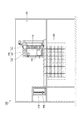
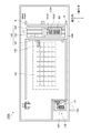
図1乃至図3に示すように、本発明の一実施例である低温保管システム100は、複数の容器Cをそれぞれ保持する複数の保管プレートBを鉛直方向すなわち上下方向に重ねてそれぞれ収容する複数の保管ラック110と、複数の保管ラック110を格納する低温格納室120と、低温格納室120に隣接して設けられた作業室130と、作業室130内に設けられ保管プレートBを搬送するとともに保管ラック110に出し入れするプレート搬送機構140と、容器Cを個別に取り出し可能に構成されたピックアップ機構150とを備えている。
First, an embodiment of the low-temperature storage system of the present invention will be described with reference to FIGS.
As shown in FIGS. 1 to 3, a low
ここで、前述したプレート搬送機構140は、低温格納室120に格納された複数の保管ラック110のうち任意の保管ラック110を個別に昇降自在に出し入れする保管ラック昇降機構141と、保管ラック110に格納された複数の保管プレートBのうち任意の保管プレートBを、上方に引き出された保管ラック110から個別に水平方向に引き出して出し入れする保管プレート引出機構142と、縦移動スライド部分143A及び横移動スライド部分143Bからなる搬送用移動体143とを有している。
なお、本実施例では、保管ラック昇降機構141、保管プレート引出機構142及び搬送用移動体143が、本発明における「保管ラック昇降手段」、「保管ラック引出手段」及び「搬送用移動手段」の一例である。
Here, the
In this embodiment, the storage rack lifting /
また、保管ラック昇降機構141および保管プレート引出機構142は、水平前後方向に移動可能な縦移動スライド部分143Aに支持されている。そして、この縦移動スライド部分143Aは、縦移動スライド部分143Aの移動方向と直交する水平左右方向、すなわち、横方向に沿ってレールR上を移動可能に構成された横移動スライド部分143Bに支持されている。
さらに、プレート搬送機構140は、縦移動スライド部分143Aおよび横移動スライド部分143Bの移動に応じて作業室130内を移動するように構成されている。
また、保管プレート引出機構142は、入出庫室170に対向する位置およびピックアップ機構150に対向する位置において、保管プレートBをプレート載置部152およびプレート旋回テーブル180に移載可能に構成されている。
Further, the storage
Further, the
The storage
そして、ピックアップ機構150は、作業室130の隅に設置されている。また、このピックアップ機構150は、複数の保管プレートBを載置可能なプレート載置部152と、プレート載置部152の上方を移動可能で容器Bを個別に取り出し、挿入可能な把持部を持つピックアップアーム151とを備えて構成されている。
このため、ピックアップ機構150は、複数の保管プレートBの間で相互に容器Cを個別且つ自動的に移載することが可能になっている。
The
For this reason, the
また、本実施例の低温保管システム100は、ピックアップ機構150に隣り合う位置に設けられた入出庫室170と、入出庫室170内に搬出入される保管プレートBを載置するとともにプレート出入口190に面した方向とプレート搬送機構140に面した方向に旋回させるプレート旋回テーブル180とを有している。
The low-
後述するように、プレート搬送機構140は、保管ラック昇降機構141が作動する低温格納室120の上方位置と入出庫室170に対向する位置とピックアップ機構150に対向する位置との間で移動自在になっている。
As will be described later, the
図3に示すように、保管プレートBは、複数の容器Cをマトリクス状に収容して保管するとともにプレート搬送機構140により搬送される。他方、容器Cは、所謂創薬用マイクロチューブと呼ばれるものであって、試料を溶解した溶液を収容する小型且つ筒状の容器本体C1と、容器本体C1に溶液を密封するキャップC2とで構成されている。
As shown in FIG. 3, the storage plate B stores and stores a plurality of containers C in a matrix and is transported by the
図4乃至図7を参照しながら、低温保管システム100における容器Bの搬出動作を説明する。
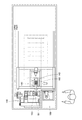
図4に示すように、作業者Pが、空の保管プレートB1を入出庫室170の側面のプレート出入口190からプレート旋回テーブル180に載置し、プレート出入口190を閉じた後に、不図示の制御装置に開始指示を与える。そして、プレート出入口190から搬入されてプレート旋回テーブル180に載置された空の保管プレートB1は、プレート旋回テーブル180が旋回することにより、プレート搬送機構140に対向する側に向けられる。この状態で、プレート搬送機構140の保管プレート引出機構142が、空の保管プレートB1をプレート旋回テーブル180から取り出す。
The carrying-out operation of the container B in the low
As shown in FIG. 4, after the operator P places an empty storage plate B1 on the plate turning table 180 from the plate entrance /
続いて、図5に示すように、保管プレート引出機構142が、ピックアップ機構150のプレート載置部152に空の保管プレートB1を移載する。
Subsequently, as shown in FIG. 5, the storage
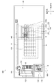
続いて、図6に示すように、プレート搬送機構140が、取り出し対象の保管プレートB2が収容された保管ラック110の位置まで移動する。ここで、保管ラック昇降機構141は、保管ラック110を低温格納室120から上方に引き上げる。その際、保管プレート引出機構142は、取り出したい容器Cを収容している保管プレートB2を保管ラック110から取り出す。
Subsequently, as shown in FIG. 6, the
続いて、図7に示すように、プレート搬送機構140が移動し、取り出したい容器Cを収容する保管プレートB2が保管プレート引出機構142によってピックアップ機構150のプレート載置部152に移載される。そして、空の保管プレートB1と取り出したい容器Cを収容する保管プレートB2とがピックアップ機構150のプレート載置部152に載置された状態で、ピックアップアーム151がプレート載置部152上方に移動して、取り出したい容器Cを収容する保管プレートB2から目的の容器Cをピックアップして空の保管プレートB1に移載する。
Subsequently, as shown in FIG. 7, the
取り出したい容器Cの空の保管プレートB1への移載が完了すると、上述した動作と逆の手順で、取り出したい容器Cが移載された保管プレートB1を入出庫室170まで搬送する。
すなわち、取り出したい容器Cのみがピックアップされた保管プレートB2が、図6に示すように、ピックアップ機構150のプレート載置部152から保管プレート引出機構142に再び取り出され、プレート搬送機構140により保管ラック110の位置まで搬送される。
When the transfer of the container C to be taken out to the empty storage plate B1 is completed, the storage plate B1 on which the container C to be taken out is transferred is transported to the loading /
That is, the storage plate B2 in which only the container C to be taken out is picked up is taken out again from the
そして、保管ラック昇降機構141が保管ラック110を低温格納室120から上方に引き上げ、保管プレートB2が保管プレート引出機構142により保管ラック110に収容される。その後、保管プレートB2を収容した保管ラック110は、再度低温格納室120に格納される。
Then, the storage
続いて、取り出したい容器Cが移載された保管プレートB1は、保管プレート引出機構142によって、ピックアップ機構150のプレート載置部152から取り出し、プレート旋回テーブル180に移載される。そして、プレート旋回テーブル180が旋回することにより、保管プレートB1がプレート出入口190側に向けられ、入出庫室170の側面のプレート出入口190から作業者Pが取り出し可能となる。
以上のように動作することにより、低温保管システム100は、取り出したい容器Cを収容する保管プレートB2を作業室106から外部搬出しないで保管プレートB2から個別且つ自動的に容器Cを移載して取り出し可能になっている。
Subsequently, the storage plate B <b> 1 on which the container C to be taken out is transferred is taken out from the
By operating as described above, the low
次に、図1乃至図7を参照しながら、本実施例の低温保管システム100が最も特徴とする低温収容槽160の具体的な形態について説明する。
図1乃至図7に示すように、低温保管システム100では、保管プレートBを収容する低温収容槽160が、プレート搬送機構140に付設されていることにより、作業室130より低温の低温収容槽160内に収容された保管プレートBや保管プレートB内における容器Cの温度上昇が抑制されるとともに保管プレートB及び容器Cと作業室130とに比べて保管プレートB及び容器Cと低温収容槽160との温度差が小さくなる。このため、容器Cに収容された試料の温度上昇を抑制するとともに低露点環境を実現して容器Cや保管プレートBに生じがちな結露や霜を防いでいる。
Next, a specific form of the low-
As shown in FIGS. 1 to 7, in the low-
また、本実施例の低温保管システム100では、プレート搬送機構140が、保管ラック110を低温格納室120から作業室130に個別に昇降自在に出し入れする保管ラック昇降機構141と、保管ラック110から保管プレートBを個別に出し入れする保管プレート引出機構142と、保管ラック昇降機構141及び保管プレート引出機構142を設置した状態で作業室130内を移動可能に構成された搬送用移動体143とを有していることにより、低温格納室120から取り出された保管プレートBの上下方向及び水平方向への移動動作や作業室130内での搬送動作が迅速になる。このため、低温格納室120から取り出された保管プレートBやこの保管プレートBにおける容器Cの温度上昇に繋がるプレート搬送時間を短縮して試料の温度上昇を抑制している。
Further, in the low
そして、本実施例の低温保管システム100では、低温格納室120が−80℃以下の超低温環境に保たれ、作業室130が低湿度環境に保たれていることにより、保管プレートB及び保管プレートBに保持された容器Cが−80℃以下の超低温状態で作業室130内に取り出されても保管プレートB及び容器Cの表面で凝縮する水蒸気が少なくなる。このため、容器Cや保管プレートBに発生し得る結露や霜の発生量を容器C内の試料の保存状態に悪影響を及ぼさない程度まで低減している。
また、入出庫室170から作業室130を隔離するように入出庫室170と作業室130との間にシャッターを設けることにより、作業室130の低湿度環境を維持してもよい。
In the low
Moreover, the low humidity environment of the
このようにして得られた本実施例の低温保管システム100は、保管プレートBを収容する低温収容槽160がプレート搬送機構140に付設されていることにより、容器Cに収容された試料の温度上昇や保管プレートの温度上昇を抑制するとともに容器Cや保管プレートBに生じがちな結露や霜を低露点環境を実現した状態で防ぐことができるなど、その効果は甚大である。
In the low
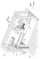
次に、図8および図9を参照しながら、本発明に係る低温保管システムの他の実施例を説明する。
なお、本実施例に係る低温保管システム100Aは、ピックアップ機構150Aがプレート搬送機構140に付設され、容器Cの移載すなわちピックアップが低温収容槽160内で行われる点で上述の低温保管システム100と構成が異なる。このため、低温保管システム100、200相互で共通する部分について共通の参照符号を付し、その詳細な説明を省略している。
Next, another embodiment of the cryogenic storage system according to the present invention will be described with reference to FIGS.
The low-
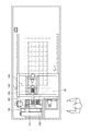
図8および図9に示すように、本実施例に係る低温保管システム100Aでは、ピックアップ機構150Aが、作業室130に隣接して設けられた入出庫室170からプレート搬送機構140によって搬送された保管プレートB1とプレート搬送機構140によって保管ラック110から取り出された保管プレートB2との間で容器Cを低温収容槽160内で個別に移載可能に構成された状態でプレート搬送機構140に付設されている。すなわち、ピックアップ機構150Aが、保管プレート引出機構142との間で保管プレートBを相互に入れ替え可能に構成されたプレート載置部152Aと、図中鉛直方向及び横方向に移動可能なピックアップアーム151Aとで構成され、低温収容槽160内の複数の保管プレートB間で相互に容器Cを移載可能に構成されている。
このようにして得られた本実施例の低温保管システム100Aでは、保管プレートBの搬送途中だけでなく容器Cの移載途中においても保管プレートB及び保管プレートB内の容器Cが作業室130より低温の低温環境下にあるため、容器移載時の試料の温度上昇を抑制するとともに容器移載時に低露点環境を実現した状態で容器Cや保管プレートBに生じ得る結露や霜を防いでいる。
As shown in FIGS. 8 and 9, in the low
In the low-
加えて、プレート搬送機構140に対してピックアップ機構150Aを離間配置する場合に比べて、保管ラック110から取り出した保管プレートBをピックアップ機構150Aまで搬送する搬送距離が短くなることで保管プレートBを保管ラック110から取り出して再度保管ラック110に収納するまでの時間が短縮される。このため、保管ラック110及び保管ラック110に収納された保管プレートBが低温格納室120から搬出されている時間を短縮して結露や霜が生じる機会を低減している。
In addition, as compared with the case where the
このとき、ピックアップ機構150Aに設けられて保管プレートBを載置するプレート載置部152Aが局所的に低温化される。このため、容器移載時に低温格納室120から出たばかりの容器C及び保管プレートBとこれらの周辺空間との温度差を増大し難くして結露や霜を防いでいる。
なお、ピックアップ機構150Aのプレート載置部151Aは、低温格納室120と同様に−80℃以下の超低温環境に保たれているほうが容器Cや保管プレートBに発生し得る結露や霜の発生量を容器C内の試料の保存状態に悪影響を及ぼさない程度まで低減するうえでより好ましい。
At this time, the
In addition, the
100、100A ・・・ 低温保管システム
110 ・・・ 保管ラック
120 ・・・ 低温格納室
130 ・・・ 作業室
140 ・・・ プレート搬送機構
141 ・・・ 保管ラック移動機構
142 ・・・ 保管プレート移動機構
143 ・・・ 搬送用移動体
143A ・・・ 縦移動スライド部分
143B ・・・ 横移動スライド部分
150、150A ・・・ ピックアップ機構
151、151A ・・・ ピックアップアーム
152、152A ・・・ プレート載置部
160 ・・・ 低温収容槽
170 ・・・ 入出庫室
180 ・・・ プレート旋回テーブル
190 ・・・ プレート出入口
B、B1、B2 ・・・ 保管プレート
C ・・・ 容器
C1 ・・・ 容器本体
C2 ・・・ キャップ
100, 100A ... Low
Claims (4)
前記保管プレートを収容する低温収容槽が、前記プレート搬送機構に付設されていることを特徴とする低温保管システム。 A plurality of storage racks that respectively accommodate a plurality of storage plates that respectively hold a plurality of containers in the vertical direction, a low-temperature storage chamber that stores the plurality of storage racks, and a work chamber provided adjacent to the low-temperature storage chamber A low-temperature storage system provided with a plate transport mechanism that is provided in the working chamber and transports the storage plate and puts it in and out of the storage rack; and a pickup mechanism configured to be able to take out the containers individually;
A low temperature storage system, wherein a low temperature storage tank for storing the storage plate is attached to the plate transport mechanism.
前記作業室が、低湿度環境に保たれていることを特徴とする請求項1乃至請求項3のいずれか一つに記載の低温保管システム。 The low-temperature storage room is kept in an ultra-low temperature environment of −80 ° C. or lower,
The low temperature storage system according to any one of claims 1 to 3, wherein the work chamber is maintained in a low humidity environment.
Priority Applications (1)
| Application Number | Priority Date | Filing Date | Title |
|---|---|---|---|
| JP2012148790A JP5843711B2 (en) | 2012-07-02 | 2012-07-02 | Cryogenic storage system |
Applications Claiming Priority (1)
| Application Number | Priority Date | Filing Date | Title |
|---|---|---|---|
| JP2012148790A JP5843711B2 (en) | 2012-07-02 | 2012-07-02 | Cryogenic storage system |
Publications (2)
| Publication Number | Publication Date |
|---|---|
| JP2014009089A true JP2014009089A (en) | 2014-01-20 |
| JP5843711B2 JP5843711B2 (en) | 2016-01-13 |
Family
ID=50106108
Family Applications (1)
| Application Number | Title | Priority Date | Filing Date |
|---|---|---|---|
| JP2012148790A Active JP5843711B2 (en) | 2012-07-02 | 2012-07-02 | Cryogenic storage system |
Country Status (1)
| Country | Link |
|---|---|
| JP (1) | JP5843711B2 (en) |
Cited By (3)
| Publication number | Priority date | Publication date | Assignee | Title |
|---|---|---|---|---|
| JP2015071480A (en) * | 2013-10-03 | 2015-04-16 | 株式会社椿本チエイン | Thermal insulation top plate and low temperature storage system |
| JP2017190191A (en) * | 2016-04-11 | 2017-10-19 | 株式会社椿本チエイン | Cold temperature storage system |
| JP2018529062A (en) * | 2015-07-20 | 2018-10-04 | ブルックス オートメーション インコーポレイテッド | Automated vault module |
Citations (5)
| Publication number | Priority date | Publication date | Assignee | Title |
|---|---|---|---|---|
| JPS5055955A (en) * | 1973-09-20 | 1975-05-16 | ||
| JPH09278118A (en) * | 1996-04-05 | 1997-10-28 | Mitsubishi Heavy Ind Ltd | Stacker crane |
| JPH1159817A (en) * | 1997-08-27 | 1999-03-02 | Takeshi Saigo | Automatic high-rise warehouse system |
| JP2008100802A (en) * | 2006-10-18 | 2008-05-01 | Ihi Corp | Substrate storage warehouse |
| JP2012056730A (en) * | 2010-09-09 | 2012-03-22 | Tsubakimoto Chain Co | Low-temperature storage system |
-
2012
- 2012-07-02 JP JP2012148790A patent/JP5843711B2/en active Active
Patent Citations (5)
| Publication number | Priority date | Publication date | Assignee | Title |
|---|---|---|---|---|
| JPS5055955A (en) * | 1973-09-20 | 1975-05-16 | ||
| JPH09278118A (en) * | 1996-04-05 | 1997-10-28 | Mitsubishi Heavy Ind Ltd | Stacker crane |
| JPH1159817A (en) * | 1997-08-27 | 1999-03-02 | Takeshi Saigo | Automatic high-rise warehouse system |
| JP2008100802A (en) * | 2006-10-18 | 2008-05-01 | Ihi Corp | Substrate storage warehouse |
| JP2012056730A (en) * | 2010-09-09 | 2012-03-22 | Tsubakimoto Chain Co | Low-temperature storage system |
Cited By (4)
| Publication number | Priority date | Publication date | Assignee | Title |
|---|---|---|---|---|
| JP2015071480A (en) * | 2013-10-03 | 2015-04-16 | 株式会社椿本チエイン | Thermal insulation top plate and low temperature storage system |
| JP2018529062A (en) * | 2015-07-20 | 2018-10-04 | ブルックス オートメーション インコーポレイテッド | Automated vault module |
| US11209344B2 (en) | 2015-07-20 | 2021-12-28 | Brooks Automation, Inc. | Automated vault module |
| JP2017190191A (en) * | 2016-04-11 | 2017-10-19 | 株式会社椿本チエイン | Cold temperature storage system |
Also Published As
| Publication number | Publication date |
|---|---|
| JP5843711B2 (en) | 2016-01-13 |
Similar Documents
| Publication | Publication Date | Title |
|---|---|---|
| JP5450326B2 (en) | Cryogenic storage system | |
| US11227782B2 (en) | Vertical batch furnace assembly | |
| US8857208B2 (en) | Automated substance storage | |
| KR20140099810A (en) | Low-temperature storage system | |
| JP6147221B2 (en) | Low temperature storage and low temperature storage system | |
| EP1634496A1 (en) | Ultra-low temperature storage system | |
| TW201351552A (en) | Substrate processing apparatus | |
| US20190277868A1 (en) | Facility for handling and storing biological samples at very low temperatures | |
| JP5843711B2 (en) | Cryogenic storage system | |
| US20130287537A1 (en) | Specimen archive | |
| US7704031B2 (en) | Substrate processing apparatus | |
| KR20130118236A (en) | Substrate treatment apparatus, substrate treatment method and storage medium | |
| CN106461694B (en) | Equipment for storing and taking out a large amount of test tubes | |
| JP6068663B2 (en) | Substrate processing apparatus, semiconductor device manufacturing method, and recording medium | |
| US20150340253A1 (en) | Semiconductor processing assembly and facility | |
| KR20150089947A (en) | Substrate heat treatment apparatus, method of installing substrate heat treatment apparatus | |
| JP6342378B2 (en) | Low temperature transfer unit | |
| JP6204226B2 (en) | Substrate processing apparatus and substrate processing method | |
| JP2012199304A (en) | Substrate processing device | |
| JP2016117570A (en) | Storage system | |
| JP6283557B2 (en) | Low temperature storage and low temperature storage system | |
| KR20210054992A (en) | Substrate processing apparatus and substrate receptacle storage method | |
| JP4023589B2 (en) | Automatic warehouse equipment | |
| TW202106472A (en) | Low-temperature storage system | |
| JP2017048035A (en) | Low temperature storage system |
Legal Events
| Date | Code | Title | Description |
|---|---|---|---|
| A621 | Written request for application examination |
Free format text: JAPANESE INTERMEDIATE CODE: A621 Effective date: 20140912 |
|
| A977 | Report on retrieval |
Free format text: JAPANESE INTERMEDIATE CODE: A971007 Effective date: 20150522 |
|
| A131 | Notification of reasons for refusal |
Free format text: JAPANESE INTERMEDIATE CODE: A131 Effective date: 20150526 |
|
| A521 | Written amendment |
Free format text: JAPANESE INTERMEDIATE CODE: A523 Effective date: 20150701 |
|
| TRDD | Decision of grant or rejection written | ||
| A01 | Written decision to grant a patent or to grant a registration (utility model) |
Free format text: JAPANESE INTERMEDIATE CODE: A01 Effective date: 20151117 |
|
| A61 | First payment of annual fees (during grant procedure) |
Free format text: JAPANESE INTERMEDIATE CODE: A61 Effective date: 20151117 |
|
| R150 | Certificate of patent or registration of utility model |
Ref document number: 5843711 Country of ref document: JP Free format text: JAPANESE INTERMEDIATE CODE: R150 |