JP2014006706A - Electronic apparatus and program - Google Patents

Electronic apparatus and program Download PDF

Info

Publication number
JP2014006706A
JP2014006706A JP2012141954A JP2012141954A JP2014006706A JP 2014006706 A JP2014006706 A JP 2014006706A JP 2012141954 A JP2012141954 A JP 2012141954A JP 2012141954 A JP2012141954 A JP 2012141954A JP 2014006706 A JP2014006706 A JP 2014006706A
Authority
JP
Japan
Prior art keywords
unit
user
pattern
terminal device
authentication
Prior art date
Legal status (The legal status is an assumption and is not a legal conclusion. Google has not performed a legal analysis and makes no representation as to the accuracy of the status listed.)
Pending
Application number
JP2012141954A
Other languages
Japanese (ja)
Inventor
Naohito Nakahara
尚人 中原
Current Assignee (The listed assignees may be inaccurate. Google has not performed a legal analysis and makes no representation or warranty as to the accuracy of the list.)
Nikon Corp
Original Assignee
Nikon Corp
Priority date (The priority date is an assumption and is not a legal conclusion. Google has not performed a legal analysis and makes no representation as to the accuracy of the date listed.)
Filing date
Publication date
Application filed by Nikon Corp filed Critical Nikon Corp
Priority to JP2012141954A priority Critical patent/JP2014006706A/en
Publication of JP2014006706A publication Critical patent/JP2014006706A/en
Pending legal-status Critical Current

Links

Images

Abstract

PROBLEM TO BE SOLVED: To provide an electronic apparatus which can prevent a predetermined operation pattern for a user to release a locked state from being easily discovered by a third person.SOLUTION: An electronic apparatus comprises: an authentication unit which authenticates a user; a display unit which has an operation detection unit for detecting operations performed on a display surface and displays information indicating detection areas arranged in a range in which the operation detection unit detects operations; a setting unit which, according to at least an authentication result by the authentication unit, sets an arrangement pattern of the plurality of detection areas that detect an operation pattern for releasing an operation locked state in which any operation input is not accepted; and a display control unit which, when the apparatus is in the operation locked state, controls the display unit to display information indicating the plurality of detection areas that detect the operation pattern for releasing the operation locked state according to the arrangement pattern set by the setting unit.

Description

本発明は、電子機器、およびプログラムに関する。   The present invention relates to an electronic device and a program.

タッチパネルを備えた電子機器において、その電子機器が操作を受け付けない操作ロック状態を解除する方法として、ユーザがタッチパネルの表示面に対して所定の操作パターンに従った操作ロック状態を解除する操作を行うことにより解除する方法がある(例えば、特許文献1参照)。   In an electronic device equipped with a touch panel, as a method of releasing an operation lock state in which the electronic device does not accept an operation, a user performs an operation to release an operation lock state according to a predetermined operation pattern on the display surface of the touch panel. There is a method of canceling by this (for example, refer to Patent Document 1).

米国特許第7657849号明細書US Pat. No. 7,657,849

しかしながら、ユーザが操作ロック状態を解除するための所定の操作パターンに従った同じ操作を繰り返し行った場合、表示面に対して操作した指の軌跡が残ってしまい操作ロック状態を解除する操作パターンを他者によって容易に解読されてしまう可能性があった。   However, if the user repeatedly performs the same operation according to a predetermined operation pattern for releasing the operation lock state, the operation pattern for releasing the operation lock state is left because the locus of the operated finger remains on the display surface. It could be easily deciphered by others.

本発明は、このような事情に鑑みてなされたもので、その目的は、ユーザが操作ロック状態を解除するための所定の操作パターンを容易に解読されないようにすることができる電子機器、およびプログラムを提供することにある。   The present invention has been made in view of such circumstances, and an object thereof is an electronic device and a program that can prevent a user from easily deciphering a predetermined operation pattern for releasing the operation lock state. Is to provide.

この発明は上述した課題を解決するためになされたもので、本発明は、ユーザを認証する認証部と、表示面に対する操作を検出する操作検出部を有し、前記操作検出部が操作を検出する範囲内に配置される検出領域を示す情報を表示する表示部と、少なくとも何れかの操作入力を受け付けない操作ロック状態を解除する操作パターンを検出する複数の前記検出領域の配置パターンを、前記認証部の認証結果に応じて設定する設定部と、前記操作ロック状態において、前記設定部が設定した前記配置パターンに従って、前記操作ロック状態を解除する操作パターンを検出する複数の前記検出領域を示す情報を前記表示部に表示させる表示制御部と、を備えることを特徴とする電子機器である。   The present invention has been made to solve the above-described problems. The present invention includes an authentication unit that authenticates a user and an operation detection unit that detects an operation on a display surface, and the operation detection unit detects the operation. A display unit that displays information indicating a detection area that is arranged within a range to be detected, and an arrangement pattern of the plurality of detection areas that detects an operation pattern that releases an operation lock state that does not accept at least any operation input, A setting unit that is set according to an authentication result of an authentication unit, and a plurality of the detection areas that detect an operation pattern for releasing the operation lock state according to the arrangement pattern set by the setting unit in the operation lock state. An electronic apparatus comprising: a display control unit that displays information on the display unit.

また、本発明は、ユーザを認証する認証部と、表示面に対する操作を検出する操作検出部を有し、前記操作検出部が操作を検出する範囲内に配置される検出領域を示す情報を表示する表示部と、を有する電子機器が備えるコンピュータに、少なくとも何れかの操作入力を受け付けない操作ロック状態を解除する操作パターンを検出する複数の前記検出領域の配置パターンを、前記認証部の認証結果に応じて設定する設定ステップと、前記操作ロック状態において、前記設定ステップにおいて設定した前記配置パターンに従って、前記操作ロック状態を解除する操作パターンを検出する複数の前記検出領域を示す情報を前記表示部に表示させる表示制御ステップと、を実行させるためのプログラムである。   In addition, the present invention includes an authentication unit that authenticates a user and an operation detection unit that detects an operation on a display surface, and displays information indicating a detection area arranged within a range in which the operation detection unit detects an operation. A plurality of detection area arrangement patterns for detecting an operation pattern for releasing an operation lock state in which at least any of the operation inputs is not received by a computer included in the electronic device including the display unit. A setting step that is set according to the information, and information indicating a plurality of detection areas that detect an operation pattern for releasing the operation lock state according to the arrangement pattern set in the setting step in the operation lock state. Display control step to be displayed on the program.

この発明によれば、ユーザが操作ロック状態を解除するための所定の操作パターンを容易に解読されないようにすることができる。   According to the present invention, it is possible to prevent the user from easily deciphering a predetermined operation pattern for releasing the operation lock state.

この発明の一実施形態による端末装置の構成を示すブロック図である。It is a block diagram which shows the structure of the terminal device by one Embodiment of this invention. 第1実施形態によるロック解除画面の第1例を示す図である。It is a figure which shows the 1st example of the lock release screen by 1st Embodiment. 第1実施形態によるロック解除画面の第2例を示す図である。It is a figure which shows the 2nd example of the lock release screen by 1st Embodiment. 第1実施形態によるロック解除画面の第3例を示す図である。It is a figure which shows the 3rd example of the lock release screen by 1st Embodiment. 第1実施形態による端末装置がロック状態を解除する処理の一例を示すフローチャートである。It is a flowchart which shows an example of the process which the terminal device by 1st Embodiment cancel | releases a locked state. 第2実施形態による端末装置の構成を示すブロック図である。It is a block diagram which shows the structure of the terminal device by 2nd Embodiment. 第2実施形態によるロック解除画面の第1例を示す図である。It is a figure which shows the 1st example of the lock release screen by 2nd Embodiment. 第2実施形態によるロック解除画面の第2例を示す図である。It is a figure which shows the 2nd example of the lock release screen by 2nd Embodiment. 第2実施形態によるロック解除画面の第3例を示す図である。It is a figure which shows the 3rd example of the lock release screen by 2nd Embodiment. 第2実施形態による端末装置がロック状態を解除する処理の一例を示すフローチャートである。It is a flowchart which shows an example of the process which the terminal device by 2nd Embodiment cancel | releases a locked state.

以下、図面を参照して、本発明の実施の形態について説明する。
<第1実施形態>
図1は、この発明の一実施形態による電子機器の構成を示す概略ブロック図である。
図1に示す電子機器は、タッチパネルを備えたタブレット型の端末装置10である。端末装置10は、登録されたユーザに対してのみ端末装置10が有する機能が利用可能なように、操作を受け付けない操作ロック状態(以下、ロック状態と称する)を解除するには、タッチパネルに対してロック状態を解除する所定の操作パターンに従ったタッチ操作が必要なように構成されている。以下、図1を参照して、端末装置10の構成について説明する。
Embodiments of the present invention will be described below with reference to the drawings.
<First Embodiment>
FIG. 1 is a schematic block diagram showing the configuration of an electronic device according to an embodiment of the present invention.
The electronic device illustrated in FIG. 1 is a tablet terminal device 10 including a touch panel. In order to release an operation lock state that does not accept an operation (hereinafter referred to as a lock state) so that the terminal device 10 can use the functions of the terminal device 10 only for registered users, Thus, a touch operation according to a predetermined operation pattern for releasing the locked state is required. Hereinafter, the configuration of the terminal device 10 will be described with reference to FIG.

端末装置10は、撮像部2、タッチパネル部3(タッチパネル)、記憶部4、及び制御部5を備えている。撮像部2は、端末装置10を使用するユーザを撮影可能なように、例えばタッチパネル部3と同じ側の筐体に配置されている。すなわち、撮像部2は、端末装置10の筐体において、端末装置10を使用するユーザ(タッチパネル部3を操作するユーザ)に対面する側に配置されている。そして、撮像部2は、端末装置10を使用しているユーザ、すなわちタッチパネル部3に対面する方向にいるユーザを撮像する。また、撮像部2は、光学レンズと、当該光学レンズを介して入力される光学像を撮像する撮像素子と、当該撮像素子に撮像された画像をデジタル画像信号として出力する撮像信号処理部と、を有している。また、撮像部2は、後述する制御部5が備えている認証部51に撮像した画像(デジタル画像信号)を供給する。   The terminal device 10 includes an imaging unit 2, a touch panel unit 3 (touch panel), a storage unit 4, and a control unit 5. The imaging unit 2 is disposed, for example, in a casing on the same side as the touch panel unit 3 so that a user who uses the terminal device 10 can be photographed. That is, the imaging unit 2 is disposed on the side of the casing of the terminal device 10 that faces the user who uses the terminal device 10 (the user who operates the touch panel unit 3). Then, the imaging unit 2 images a user who is using the terminal device 10, that is, a user who is in a direction facing the touch panel unit 3. The imaging unit 2 includes an optical lens, an imaging element that captures an optical image input via the optical lens, an imaging signal processing unit that outputs an image captured by the imaging element as a digital image signal, have. The imaging unit 2 supplies the captured image (digital image signal) to the authentication unit 51 provided in the control unit 5 described later.

タッチパネル部3は、表示部31と、表示部31の表示面に対するタッチ操作(接触操作)を検出する操作検出部32と、を備えている。表示部31は、例えば液晶ディスプレイ又は有機EL(Electro Luminescence)ディスプレイ等を含んで構成され、情報又は画像を表示する。また、表示部31は、タッチパネル部3に対するタッチ操作を検出する検出領域を示す情報を表示する。例えば、表示部31は、操作検出部32が操作を検出する範囲内に配置される検出領域を示す情報を表示する。   The touch panel unit 3 includes a display unit 31 and an operation detection unit 32 that detects a touch operation (contact operation) on the display surface of the display unit 31. The display unit 31 includes, for example, a liquid crystal display or an organic EL (Electro Luminescence) display, and displays information or an image. Further, the display unit 31 displays information indicating a detection area in which a touch operation on the touch panel unit 3 is detected. For example, the display unit 31 displays information indicating a detection area arranged within a range in which the operation detection unit 32 detects an operation.

操作検出部32は、表示部31の表示面に対するタッチ操作(接触操作)を検出するタッチセンサを含んで構成されている。このタッチセンサは、表示部31の表示面に配置され、タッチ操作により触れられた位置を検出する。なお、タッチセンサは、静電容量方式、抵抗膜方式、電磁誘導方式、又はその他の方式の何れのタッチセンサでもよい。
例えば、操作検出部32は、表示部31の表示面に対するタッチ操作に応じてタッチ操作された位置を検出し、検出結果を制御部5に出力する。
The operation detection unit 32 includes a touch sensor that detects a touch operation (contact operation) on the display surface of the display unit 31. The touch sensor is disposed on the display surface of the display unit 31 and detects a position touched by a touch operation. Note that the touch sensor may be any touch sensor of a capacitance method, a resistance film method, an electromagnetic induction method, or other methods.
For example, the operation detection unit 32 detects the position where the touch operation is performed in response to the touch operation on the display surface of the display unit 31, and outputs the detection result to the control unit 5.

記憶部4は、ユーザを特定するユーザ情報が予め登録されているユーザ情報記憶部41と、表示部31の表示面に対するタッチ操作の操作パターンを示す情報を記憶する操作パターン記憶部42と、を備えている。   The storage unit 4 includes a user information storage unit 41 in which user information for specifying a user is registered in advance, and an operation pattern storage unit 42 that stores information indicating an operation pattern of a touch operation on the display surface of the display unit 31. I have.

ユーザ情報記憶部41は、端末装置10の所有者又は主使用者であるユーザを特定するユーザ情報を記憶する。例えば、ユーザ情報記憶部41は、ユーザ情報として、ユーザを識別する識別情報(ユーザID)と、そのユーザの顔画像又は顔画像の特徴量を示す情報と、を関連付けて記憶する。このユーザ情報は、ユーザが、例えば端末装置10を初めて使用するときに登録したアカウント情報である。つまり、ユーザ情報記憶部41にユーザ情報が記憶(登録)されているユーザは端末装置10の所有者又は主使用者本人である。一方、ユーザ情報記憶部41にユーザ情報が記憶(登録)されていないユーザは端末装置10の所有者又は主使用者本人とは異なる他者である。   The user information storage unit 41 stores user information that identifies a user who is an owner or a main user of the terminal device 10. For example, the user information storage unit 41 stores, as user information, identification information (user ID) for identifying the user and information indicating the face image of the user or the feature amount of the face image in association with each other. This user information is account information registered when the user uses the terminal device 10 for the first time, for example. That is, the user whose user information is stored (registered) in the user information storage unit 41 is the owner of the terminal device 10 or the main user. On the other hand, the user whose user information is not stored (registered) in the user information storage unit 41 is a different person from the owner of the terminal device 10 or the main user.

なお、ユーザ情報記憶部41は、1人のユーザ情報を記憶することに限られるものではなく、複数人のユーザ情報を記憶してもよい。また、このユーザ情報に含まれるユーザIDと関連付けられた顔画像又は顔画像の特徴量は、後述する制御部5が備えている認証部51がユーザを認証する際に用いられるユーザ情報である。また、端末装置10は、この顔画像又は顔画像の特徴量を、撮像部2が撮像した所有者又は主使用者であるユーザの顔画像に基づいて予め生成してもよいし、予め他の機器で生成され、記憶媒体や無線通信を介して取得したものであってもよい。   Note that the user information storage unit 41 is not limited to storing user information of one person, and may store user information of a plurality of persons. Further, the face image or the feature amount of the face image associated with the user ID included in the user information is user information used when the authentication unit 51 provided in the control unit 5 described later authenticates the user. Further, the terminal device 10 may generate the face image or the feature amount of the face image in advance based on the face image of the user who is the owner or the main user captured by the imaging unit 2, It may be generated by a device and acquired via a storage medium or wireless communication.

操作パターン記憶部42は、後述するロック解除画面において、ロック状態を解除する操作パターンを示す情報を記憶している。例えば、操作パターン記憶部42は、予め設定されたロック状態を解除する操作パターンを示す情報、又はユーザにより設定されたロック状態を解除する操作パターンを示す情報を記憶する。また、操作パターン記憶部42は、ユーザにより設定されたロック状態を解除する操作パターンを、ユーザIDに関連付けて記憶する。   The operation pattern storage unit 42 stores information indicating an operation pattern for releasing the lock state on an unlock screen described later. For example, the operation pattern storage unit 42 stores information indicating an operation pattern for releasing a preset lock state or information indicating an operation pattern for releasing a lock state set by a user. Further, the operation pattern storage unit 42 stores an operation pattern for releasing the lock state set by the user in association with the user ID.

制御部5は、端末装置10が備える各部の動作を制御する。例えば、制御部5は、端末装置10の動作状態を、端末装置10が有する機能を実行させる操作入力を受け付ける通常動作状態と、端末装置10が有する機能のうちの少なくとも何れかの機能を実行させる操作入力を受け付けないロック状態と、のうちの何れかに制御する。例えば、制御部5は、電源起動時において、端末装置10の動作状態をまずロック状態になるように起動し、その後ユーザによりロック状態を解除する操作が入力されることに応じて、通常動作状態に遷移させる。また、制御部5は、例えば通常動作状態において操作がされない状態が長時間継続した場合、端末装置10の動作状態を通常動作状態からロック状態に遷移させる。   The control unit 5 controls the operation of each unit included in the terminal device 10. For example, the control unit 5 causes the operation state of the terminal device 10 to execute at least one of the normal operation state in which an operation input for executing the function of the terminal device 10 is received and the function of the terminal device 10. Control is made to either a locked state in which no operation input is accepted. For example, at the time of power activation, the control unit 5 starts up the operation state of the terminal device 10 so as to be in a locked state, and then the normal operation state in response to an input of an operation for releasing the lock state by the user. Transition to. Further, for example, when a state in which no operation is performed in the normal operation state continues for a long time, the control unit 5 changes the operation state of the terminal device 10 from the normal operation state to the locked state.

また、本実施形態の端末装置10は、端末装置10の動作状態がロック状態の場合、ユーザが、ロック状態を解除するためのタッチ操作を入力することが可能なロック解除画面を表示部31に表示させる。そして、端末装置10は、ロック状態において、タッチパネル部3に対してロック状態を解除する操作パターンのタッチ操作が行われた場合に、ロック状態を解除して通常動作状態に遷移する。例えば、制御部5は、端末装置10の動作状態をロック状態に遷移させた場合、ロック解除画面を表示部31に表示する。そして、制御部5は、ロック状態を解除する操作パターンのタッチ操作がされたことを操作検出部32が検出した場合、端末装置10の動作状態をロック状態から通常動作状態に遷移させ、表示部31に表示させる表示画面をロック解除画面から通常動作状態の表示画面に切り替える。   In addition, the terminal device 10 according to the present embodiment displays a lock release screen on the display unit 31 that allows the user to input a touch operation for releasing the lock state when the operation state of the terminal device 10 is the lock state. Display. Then, when the touch operation of the operation pattern for releasing the lock state is performed on the touch panel unit 3 in the lock state, the terminal device 10 releases the lock state and transitions to the normal operation state. For example, the control unit 5 displays a lock release screen on the display unit 31 when the operation state of the terminal device 10 is changed to the locked state. When the operation detection unit 32 detects that the touch operation of the operation pattern for releasing the lock state has been performed, the control unit 5 changes the operation state of the terminal device 10 from the lock state to the normal operation state, and the display unit The display screen displayed on 31 is switched from the unlock screen to the display screen in the normal operation state.

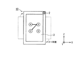
図2は、ロック解除画面の一例を示す図である。制御部5は、ロック状態を解除する操作パターンを検出する複数の検出領域を示す情報を、表示部31に表示させる。この図において、制御部5は、ロック状態を解除する操作パターンを検出するための「A」、「B」、「C」、「D」の4つの検出領域を示す情報を、それぞれ四角形の各頂点の位置関係になるような配置パターンで表示部31に表示させる。例えば、制御部5は、「A」、「B」、「C」、「D」の4つの検出領域を示す情報を、検出領域「A」が四角形の各頂点のうちの左上の頂点の位置、検出領域「B」が四角形の各頂点のうちの右上の頂点の位置、検出領域「C」が四角形の各頂点のうちの左下の頂点の位置、及び、検出領域「D」が四角形の各頂点のうちの右下の頂点の位置、となるような配置パターンで表示部31に表示させる。   FIG. 2 is a diagram illustrating an example of the unlock screen. The control unit 5 causes the display unit 31 to display information indicating a plurality of detection areas for detecting an operation pattern for releasing the locked state. In this figure, the control unit 5 displays information indicating four detection areas “A”, “B”, “C”, and “D” for detecting an operation pattern for releasing the locked state, for each of the squares. It is displayed on the display unit 31 in an arrangement pattern that has a vertex positional relationship. For example, the control unit 5 uses the information indicating the four detection areas “A”, “B”, “C”, and “D” to determine the position of the upper left vertex of the respective vertices in which the detection area “A” is a rectangle. , The detection area “B” is the position of the upper right vertex of each square vertex, the detection area “C” is the position of the lower left vertex of each square vertex, and the detection area “D” is each square It is displayed on the display unit 31 in such an arrangement pattern as to be the position of the lower right vertex of the vertices.

また、この図において、ロック状態を解除する操作パターンは、矢印101で示すように「A」、「B」、「C」の順(四角形の各頂点のうちの左上の頂点の位置、右上の頂点の位置、左下の頂点の位置、の順)に検出領域を通過するようになぞる操作パターンであることを示している。そして、制御部5は、図2の矢印101で示すようなロック状態を解除する操作パターンのタッチ操作がされたことを操作検出部32が検出した場合、端末装置10の動作状態をロック状態から通常動作状態に遷移させ、表示部31に表示させる表示画面をロック解除画面から通常動作状態の表示画面に切り替える。   Further, in this figure, the operation pattern for releasing the lock state is the order of “A”, “B”, “C” (the position of the upper left vertex of each square vertex, This indicates that the operation pattern is traced so as to pass through the detection region in the order of the vertex position and the position of the lower left vertex). When the operation detection unit 32 detects that the touch operation of the operation pattern for releasing the lock state as indicated by the arrow 101 in FIG. 2 is performed, the control unit 5 changes the operation state of the terminal device 10 from the lock state. The display screen is changed to the normal operation state, and the display screen displayed on the display unit 31 is switched from the lock release screen to the display screen in the normal operation state.

図1に戻り、制御部5の構成について詳しく説明する。
制御部5は、認証部51と、設定部52と、表示制御部53と、操作制御部54と、操作パターン判定部55と、状態制御部56と、を備えている。
Returning to FIG. 1, the configuration of the control unit 5 will be described in detail.
The control unit 5 includes an authentication unit 51, a setting unit 52, a display control unit 53, an operation control unit 54, an operation pattern determination unit 55, and a state control unit 56.

認証部51は、端末装置10を使用するユーザを認証する。例えば、認証部51は、ユーザを認証する場合、撮像部2が撮像した画像からユーザの顔画像を検出するとともに、検出した顔画像に基づいてユーザを特定する。また、認証部51は、ユーザ情報記憶部41に登録されているユーザ情報に基づいて、ユーザを認証して特定する。   The authentication unit 51 authenticates a user who uses the terminal device 10. For example, when authenticating the user, the authentication unit 51 detects the user's face image from the image captured by the image capturing unit 2 and specifies the user based on the detected face image. The authentication unit 51 authenticates and identifies the user based on the user information registered in the user information storage unit 41.

具体的には、認証部51は、ユーザ情報記憶部41を参照して、検出した顔画像と、予め登録されているユーザIDに関連付けられた顔画像とを照合する。そして、認証部51は、照合した結果、検出した顔画像が予め登録されているユーザIDに関連付けられた顔画像と合致した場合、検出した顔画像のユーザ(端末装置10を使用しようとしているユーザ)が、ユーザ情報として登録されているユーザ(すなわち、端末装置10の所有者又は主使用者本人)であると特定する。   Specifically, the authentication unit 51 refers to the user information storage unit 41 and collates the detected face image with a face image associated with a user ID registered in advance. Then, as a result of the collation, when the detected face image matches the face image associated with the user ID registered in advance, the authentication unit 51 detects the user of the detected face image (the user who intends to use the terminal device 10). ) Is specified as the user registered as the user information (that is, the owner of the terminal device 10 or the main user).

設定部52は、ロック状態を解除する操作パターンを検出する複数の検出領域の配置パターン(表示部31に表示させるロック解除画面の複数の検出領域の配置パターン)を、認証部51の認証結果に応じて設定する。例えば、設定部52は、認証部51の認証結果により、ユーザ情報記憶部41にユーザ情報として登録されているユーザが特定されたか否かに応じて、ロック解除画面の複数の検出領域の配置パターンを設定する。
この設定部52が認証部51の認証結果に応じてロック解除画面の複数の検出領域の配置パターンを設定する処理について、詳しくは後述する。
The setting unit 52 uses an arrangement pattern of a plurality of detection areas (an arrangement pattern of a plurality of detection areas on a lock release screen displayed on the display unit 31) for detecting an operation pattern for releasing the locked state as an authentication result of the authentication unit 51. Set accordingly. For example, the setting unit 52 determines the arrangement pattern of the plurality of detection areas on the unlock screen according to whether or not the user registered as the user information in the user information storage unit 41 is specified by the authentication result of the authentication unit 51. Set.
A process in which the setting unit 52 sets the arrangement pattern of the plurality of detection areas on the unlock screen according to the authentication result of the authentication unit 51 will be described in detail later.

表示制御部53は、表示部31に、情報、画像、又はタッチパネル部3におけるタッチ操作に関する操作情報を表示する制御を実行する。例えば、表示制御部53は、ロック状態において、設定部52が設定した配置パターンに従って、操作ロック状態を解除する操作パターンを検出する複数の前記検出領域を示す情報を、ロック解除画面として、表示部31に表示させる。また、表示制御部53は、表示部31の表示のオンとオフとの切り替え制御(表示状態と非表示状態との切り替え制御)等を実行する。   The display control unit 53 performs control to display information, an image, or operation information related to a touch operation on the touch panel unit 3 on the display unit 31. For example, in the locked state, the display control unit 53 displays, as a lock release screen, information indicating the plurality of detection areas for detecting an operation pattern for releasing the operation lock state according to the arrangement pattern set by the setting unit 52. 31 is displayed. In addition, the display control unit 53 performs switching control for switching on and off the display of the display unit 31 (switching control between a display state and a non-display state) and the like.

操作制御部54は、操作検出部32の検出結果に基づいて、表示部31の表示面に対してタッチ操作された位置を示す操作位置情報を生成する。また、操作制御部54は、表示制御部53が表示部31に表示した検出領域(タッチ操作を検出する検出領域)の表示位置と、生成した操作位置情報とに基づいて、タッチ操作が行われた操作内容を示す操作情報を生成する。   The operation control unit 54 generates operation position information indicating a position where the touch operation is performed on the display surface of the display unit 31 based on the detection result of the operation detection unit 32. Further, the operation control unit 54 performs the touch operation based on the display position of the detection area (detection area for detecting the touch operation) displayed on the display unit 31 by the display control unit 53 and the generated operation position information. Operation information indicating the details of the operation is generated.

操作パターン判定部55は、操作パターン記憶部42を参照して、タッチパネル部3に対してタッチ操作された操作パターンが、ロック状態を解除する操作パターンであるか否かを判定する。具体的には、操作パターン判定部55は、操作パターン記憶部42に記憶されているロック状態を解除する操作パターンを示す情報と、操作制御部54が生成した操作情報とに基づいて、タッチパネル部3に対してタッチ操作された操作パターンが、ロック状態を解除する操作パターンであるか否かを判定する。   The operation pattern determination unit 55 refers to the operation pattern storage unit 42 to determine whether or not the operation pattern touched on the touch panel unit 3 is an operation pattern for releasing the lock state. Specifically, the operation pattern determination unit 55 is based on information indicating the operation pattern for releasing the lock state stored in the operation pattern storage unit 42 and the operation information generated by the operation control unit 54. It is determined whether the operation pattern touched on 3 is an operation pattern for releasing the lock state.

状態制御部56は、端末装置10の動作状態を、端末装置10が有する機能を実行させる操作を受け付ける通常動作状態と、端末装置10が有する機能のうちの少なくとも何れかの機能を実行させる操作を受け付けないロック状態(操作ロック状態)と、のうちの何れかに制御する。また、状態制御部56は、端末装置10の動作状態をロック状態に遷移させた場合、ロック解除画面を表示制御部53を介して表示部31に表示させる。   The state control unit 56 sets the operation state of the terminal device 10 to the normal operation state for accepting an operation for executing the function of the terminal device 10 and the operation for executing at least one of the functions of the terminal device 10. Control is performed in one of a lock state (operation lock state) that is not accepted. In addition, when the operation state of the terminal device 10 is changed to the locked state, the state control unit 56 causes the display unit 31 to display the lock release screen via the display control unit 53.

また、状態制御部56は、ロック解除画面として、設定部52が設定した配置パターンに従って、ロック状態を解除する操作パターンを検出する複数の検出領域(例えば図2に示す「A」、「B」、「C」、「D」の4つの検出領域)を示す情報を、表示制御部53を介して表示部31に表示させる。   In addition, the state control unit 56 uses a plurality of detection areas (for example, “A” and “B” shown in FIG. 2) to detect an operation pattern for releasing the lock state according to the arrangement pattern set by the setting unit 52 as the lock release screen. , “C” and “D” four detection areas) are displayed on the display unit 31 via the display control unit 53.

また、状態制御部56は、ロック状態において、ロック解除画面を表示部31に表示させている際に、操作検出部32により検出された表示面に対する操作が、ロック状態を解除する操作パターンであると操作パターン判定部55により判定された場合、端末装置10の動作状態をロック状態から通常動作状態に遷移させる(ロック状態を解除する)。また、状態制御部56は、この場合、表示部31に表示する表示画面をロック解除画面から通常動作状態の表示画面に切り替える。   Further, the state control unit 56 is an operation pattern in which an operation on the display surface detected by the operation detection unit 32 releases the lock state when the lock release screen is displayed on the display unit 31 in the lock state. When the operation pattern determination unit 55 determines that the operation state of the terminal device 10 is changed from the lock state to the normal operation state (releases the lock state). In this case, the state control unit 56 switches the display screen displayed on the display unit 31 from the unlock screen to the display screen in the normal operation state.

(配置パターンの例)
次に、設定部52が、認証部51の認証結果に応じて、ロック解除画面の表示内容(配置パターン)を設定する際の配置パターンの例について、図2から図4を用いて詳しく説明する。上述したように、設定部52は、認証部51の認証結果により、ユーザ情報記憶部41にユーザ情報として登録されているユーザが特定されたか否かに応じて、ロック解除画面における複数の検出領域の配置パターンを設定する。
(Example of arrangement pattern)
Next, an example of an arrangement pattern when the setting unit 52 sets the display content (arrangement pattern) of the unlock screen according to the authentication result of the authentication unit 51 will be described in detail with reference to FIGS. . As described above, the setting unit 52 has a plurality of detection areas on the unlock screen depending on whether or not a user registered as user information in the user information storage unit 41 is specified by the authentication result of the authentication unit 51. Set the placement pattern.

ここで、認証部51が、撮像部2が撮像した画像から検出した顔画像のユーザ(端末装置10を使用しようとしているユーザ)がユーザ情報として登録されているユーザ(すなわち、端末装置10の所有者又は主使用者本人)であると特定したとする。この場合、設定部52は、ロック状態を解除する操作パターンを検出する複数の検出領域を示す情報の配置パターンを、図2に示すロック解除画面のような配置パターンに設定する。   Here, the user of the face image detected by the authentication unit 51 from the image captured by the imaging unit 2 (the user who intends to use the terminal device 10) is registered as user information (that is, owned by the terminal device 10). Or the principal user). In this case, the setting unit 52 sets an arrangement pattern of information indicating a plurality of detection areas for detecting an operation pattern for releasing the locked state to an arrangement pattern such as the unlock screen shown in FIG.

例えば、設定部52は、ロック状態を解除する操作パターンを検出する「A」、「B」、「C」、「D」の4つの検出領域を示す情報の配置パターンを、検出領域「A」が四角形の各頂点のうちの左上の頂点の位置、検出領域「B」が四角形の各頂点のうちの右上の頂点の位置、検出領域「C」が四角形の各頂点のうちの左下の頂点の位置、及び、検出領域「D」が四角形の各頂点のうちの右下の頂点の位置、となるような配置パターンに設定する。また、ロック状態を解除する操作パターンは、矢印101で示すように「A」、「B」、「C」の順に検出領域を通過するようになぞる操作パターンであって、四角形の各頂点のうちの左上の頂点の位置、右上の頂点の位置、左下の頂点の位置、の順に検出領域を通過するようになぞる操作パターンである。   For example, the setting unit 52 detects an arrangement pattern of information indicating four detection areas “A”, “B”, “C”, and “D” that detects an operation pattern for releasing the lock state, as a detection area “A”. Is the position of the upper left vertex of each square vertex, the detection area “B” is the position of the upper right vertex of each square vertex, and the detection area “C” is the lower left vertex of each square vertex. The arrangement pattern is set so that the position and the detection area “D” are the positions of the lower right vertices of the quadrangular vertices. The operation pattern for releasing the lock state is an operation pattern that traces through the detection area in the order of “A”, “B”, and “C” as indicated by an arrow 101, This is an operation pattern that traces through the detection area in the order of the position of the upper left vertex, the position of the upper right vertex, and the position of the lower left vertex.

一方、認証部51が、撮像部2が撮像した画像から検出した顔画像のユーザ(端末装置10を使用しようとしているユーザ)がユーザ情報として登録されているユーザであると特定できなかったとする。つまり、端末装置10を使用しようとしているユーザは、端末装置10の所有者又は主使用者本人とは異なる他者である(或いは、撮像部2が撮像した画像から顔画像が検出されなかった場合も含む)。この場合、設定部52は、ロック状態を解除する操作パターンを検出する複数の検出領域を示す情報の配置パターンを、図2に示すロック解除画面のような配置パターンとは異なるように、「A」、「B」、「C」、「D」の4つの検出領域の並びが異なる配置パターンに設定する。   On the other hand, it is assumed that the authentication unit 51 cannot identify that the user of the face image detected from the image captured by the imaging unit 2 (the user who intends to use the terminal device 10) is a user registered as user information. That is, the user who intends to use the terminal device 10 is a different person from the owner of the terminal device 10 or the main user himself / herself (or when a face image is not detected from the image captured by the imaging unit 2). Also included). In this case, the setting unit 52 determines that the arrangement pattern of the information indicating the plurality of detection areas for detecting the operation pattern for releasing the locked state is different from the arrangement pattern such as the unlock screen shown in FIG. ”,“ B ”,“ C ”, and“ D ”are set to different arrangement patterns.

例えば、設定部52は、図3に示すロック解除画面のように、「A」、「B」、「C」、「D」の4つの検出領域を示す情報の配置パターンを、検出領域「A」が四角形の各頂点のうちの左上の頂点の位置、検出領域「B」が四角形の各頂点のうちの左下の頂点の位置、検出領域「C」が四角形の各頂点のうちの右下の頂点の位置、及び、検出領域「D」が四角形の各頂点のうちの右上の頂点の位置、となるような配置パターンに設定する。よって、ロック状態を解除する操作パターンは、矢印102で示すように「A」、「B」、「C」の順に検出領域を通過するようになぞる操作パターンであって、四角形の各頂点のうちの左上の頂点の位置、左下の頂点の位置、右下の頂点の位置、の順に検出領域を通過するようになぞる操作パターンとなる   For example, as illustrated in the unlock screen shown in FIG. 3, the setting unit 52 changes the arrangement pattern of information indicating the four detection areas “A”, “B”, “C”, and “D” to the detection area “A”. ”Is the position of the upper left vertex of each square vertex, the detection area“ B ”is the position of the lower left vertex of each square vertex, and the detection area“ C ”is the lower right corner of each square vertex. The arrangement pattern is set so that the position of the vertex and the detection area “D” are the position of the upper right vertex of each of the quadrangular vertices. Therefore, the operation pattern for releasing the locked state is an operation pattern that traces through the detection region in the order of “A”, “B”, and “C” as indicated by an arrow 102, The operation pattern that traces through the detection area in the order of the position of the top left vertex, the position of the bottom left vertex, and the position of the bottom right vertex

このように、設定部52は、認証部51の認証結果により、ユーザ情報記憶部41にユーザ情報として登録されているユーザが特定(認証)されたか否かに応じて、ロック解除画面における複数の検出領域の配置パターンを設定する。すなわち、設定部52は、認証部51の認証結果により、端末装置10を使用しようとしているユーザが、ユーザ情報として登録されているユーザ(すなわち、端末装置10の所有者又は主使用者本人)であるか否かに応じて、互いに異なる配置パターンに設定する。つまり、端末装置10は、端末装置10の所有者又は主使用者本人であるか否かに応じて、ロック状態を解除する操作パターンによる表示面上の軌跡が異なるようにロック解除画面を表示部31に表示する。   As described above, the setting unit 52 determines whether or not a user registered as user information in the user information storage unit 41 is identified (authenticated) based on the authentication result of the authentication unit 51. Set the arrangement pattern of the detection area. That is, the setting unit 52 indicates that the user who intends to use the terminal device 10 is a user registered as user information (that is, the owner of the terminal device 10 or the main user himself / herself) based on the authentication result of the authentication unit 51. Different arrangement patterns are set according to whether or not there is. That is, the terminal device 10 displays the unlock screen so that the locus on the display surface by the operation pattern for releasing the lock state differs depending on whether the terminal device 10 is the owner or the main user. 31.

これにより、端末装置10は、ロック状態を解除する操作パターンを、表示面上に残るタッチ操作の軌跡によって他者に容易に解読されてしまうことを防止することができる。よって、端末装置10は、ユーザがロック状態を解除するための所定の操作パターンを、他者に容易に解読されないようにすることができる。   Thereby, the terminal device 10 can prevent the operation pattern for releasing the locked state from being easily deciphered by others due to the locus of the touch operation remaining on the display surface. Therefore, the terminal device 10 can prevent a predetermined operation pattern for the user to release the locked state from being easily deciphered by others.

なお、設定部52は、認証部51の認証結果に応じて、図2に示すロック解除画面の配置パターンと異なる配置パターンを設定する場合、図3に示すロック解除画面の配置パターン(図2の配置パターンとは「A」、「B」、「C」、「D」の4つの検出領域の並びが異なる配置パターン)に設定することに限られるものではなく、図2に示す配置パターンと異なる配置パターンであれば他の配置パターンに設定してもよい。   When the setting unit 52 sets an arrangement pattern different from the arrangement pattern of the unlocking screen shown in FIG. 2 according to the authentication result of the authentication unit 51, the setting unit 52 shows the arrangement pattern of the unlocking screen shown in FIG. The arrangement pattern is not limited to the arrangement pattern in which the arrangement of the four detection areas “A”, “B”, “C”, and “D” is different, and is different from the arrangement pattern shown in FIG. If it is an arrangement pattern, it may be set to another arrangement pattern.

例えば、設定部52は、図2に示すロック解除画面の配置パターンとは異なる配置パターンとして、図3に示す配置パターンに代えて、図4に示すロック解除画面のような配置パターンに設定してもよい。図4に示す配置パターンの例は、図2に示す配置パターンに対して、表示部31の表示領域内における、「A」、「B」、「C」、「D」の4つの検出領域の位置が異なる配置パターンの例であって、4つの検出領域の重心となる位置を中心として、4つの検出領域の位置を45度右に回転した配置パターンの例である。この例では、ロック状態を解除する操作パターンは、矢印103で示すように「A」、「B」、「C」の順に検出領域を通過するようになぞる操作パターンであって、図2の配置パターンに対して45度回転した四角形の各頂点(上、下、左、右、の位置の各頂点)のうちの上の頂点の位置、右の頂点の位置、左の頂点の位置、の順に検出領域を通過するようになぞる操作パターンとなる。   For example, the setting unit 52 sets an arrangement pattern such as the unlock screen shown in FIG. 4 instead of the arrangement pattern shown in FIG. 3 as an arrangement pattern different from the arrangement pattern of the unlock screen shown in FIG. Also good. The example of the arrangement pattern shown in FIG. 4 includes four detection areas “A”, “B”, “C”, and “D” in the display area of the display unit 31 with respect to the arrangement pattern shown in FIG. It is an example of an arrangement pattern with different positions, and is an example of an arrangement pattern in which the positions of the four detection areas are rotated to the right by 45 degrees with the position serving as the center of gravity of the four detection areas. In this example, the operation pattern for releasing the lock state is an operation pattern that traces through the detection area in the order of “A”, “B”, and “C” as indicated by an arrow 103, and is arranged as shown in FIG. The position of the upper vertex, the position of the right vertex, and the position of the left vertex among the vertexes (upper, lower, left, and right positions) of the square rotated 45 degrees with respect to the pattern in this order. The operation pattern is traced so as to pass through the detection region.

このように、設定部52は、端末装置10の所有者又は主使用者本人とは異なる他者がユーザの場合、図4に示すロック解除画面のような配置パターンに設定してもよい。これにより、端末装置10は、端末装置10の所有者又は主使用者本人であるか否かに応じて、ロック状態を解除する操作パターンによる表示面上の軌跡が異なるようにロック解除画面を表示部31に表示することができる。   As described above, the setting unit 52 may set an arrangement pattern such as the unlock screen shown in FIG. 4 when the user who is different from the owner of the terminal device 10 or the main user is a user. Thereby, the terminal device 10 displays the unlock screen so that the locus on the display surface by the operation pattern for releasing the lock state differs depending on whether the terminal device 10 is the owner or the main user. It can be displayed on the part 31.

(ロック状態を解除する処理の説明)
続いて、図5を参照して、端末装置10がロック状態を解除する処理の動作について説明する。
図5は、端末装置10がロック状態を解除する処理の一例を示すフローチャートである。なお、端末装置10は、動作状態をロック状態に遷移させたことに応じて、この処理を開始する。
(Explanation of processing to release the lock state)
Next, with reference to FIG. 5, an operation of a process in which the terminal device 10 releases the locked state will be described.
FIG. 5 is a flowchart illustrating an example of processing in which the terminal device 10 releases the locked state. The terminal device 10 starts this process in response to the transition of the operation state to the lock state.

まず、設定部52は、状態制御部56が端末装置10の動作状態をロック状態に遷移させたことに応じて、タイマーによる計時をスタートする(ステップS11)。なお、このタイマーは、設定部52が備えている構成としてもよいし、設定部52以外に備えられている構成としてもよい。   First, the setting unit 52 starts timing by a timer in response to the state control unit 56 changing the operation state of the terminal device 10 to the locked state (step S11). The timer may have a configuration provided in the setting unit 52 or may be provided in a configuration other than the setting unit 52.

次に、認証部51は、撮像部2が撮像した画像からユーザの顔画像を検出する(ステップS12)。続いて、認証部51は、検出した顔画像と、ユーザ情報記憶部41に登録されているユーザ情報とに基づいて、端末装置10を使用するユーザを認証する(ステップS13)。   Next, the authentication part 51 detects a user's face image from the image imaged by the imaging part 2 (step S12). Subsequently, the authentication unit 51 authenticates a user who uses the terminal device 10 based on the detected face image and user information registered in the user information storage unit 41 (step S13).

設定部52は、ステップS13における認証部51の認証結果により、ユーザ情報記憶部41にユーザ情報として登録されているユーザが特定されたか否かを判定する。すなわち、設定部52は、検出した顔画像のユーザ(端末装置10を使用しようとしているユーザ)が、ユーザ情報として登録されているユーザ(すなわち、端末装置10の所有者又は主使用者本人)であるか否かを判定する(ステップS14)。   The setting unit 52 determines whether or not a user registered as user information in the user information storage unit 41 is specified based on the authentication result of the authentication unit 51 in step S13. That is, the setting unit 52 is a user whose user of the detected face image (a user who intends to use the terminal device 10) is registered as user information (that is, the owner of the terminal device 10 or the main user). It is determined whether or not there is (step S14).

ステップS14において、端末装置10を使用しようとしているユーザが端末装置10の所有者又は主使用者本人であると判定された場合(ステップS14:YES)、設定部52は、ロック解除画面の配置パターンを第1の配置パターン(例えば、図2に示す配置パターン)に設定し(ステップS15)、ステップS31に処理を進める。   When it is determined in step S14 that the user who intends to use the terminal device 10 is the owner or the main user of the terminal device 10 (step S14: YES), the setting unit 52 displays the unlock screen layout pattern. Is set to the first arrangement pattern (for example, the arrangement pattern shown in FIG. 2) (step S15), and the process proceeds to step S31.

一方、ステップS14において、端末装置10を使用しようとしているユーザが端末装置10の所有者又は主使用者本人でないと判定された場合(ステップS14:NO)、設定部52は、ステップS11において計時をスタートしたタイマーがタイムアップしたか否かを判定する(ステップS16)。ここで、設定部52は、タイマーがタイムアップしたか否かの判定を、予め定められた時間を越えたか否かによって判定する。なお、この予め定められた時間とは、端末装置10の動作状態がロック状態に遷移した際に、ロック解除画面を表示部31に表示する前に認証部51がユーザを認証(端末装置10の所有者又は主使用者本人による認証)する時間の長さの制限として予め定められた時間である。   On the other hand, when it is determined in step S14 that the user who intends to use the terminal device 10 is not the owner of the terminal device 10 or the main user (step S14: NO), the setting unit 52 counts time in step S11. It is determined whether or not the started timer has expired (step S16). Here, the setting unit 52 determines whether or not the timer has expired based on whether or not a predetermined time has been exceeded. Note that this predetermined time means that when the operation state of the terminal device 10 transitions to the locked state, the authentication unit 51 authenticates the user before the lock release screen is displayed on the display unit 31 (of the terminal device 10). This is a predetermined time as a limitation on the length of time for the owner or the main user to authenticate.

ステップS16において、タイマーがタイムアップしていないと判定された場合(ステップS16:NO)、設定部52は、ステップS12に処理を戻す。これにより、認証部51はユーザを認証する処理を再度実行する。例えば、撮像部2が撮像した画像からユーザの顔画像が検出されなかった場合、または撮像部2が撮像した画像から検出された顔画像が、端末装置10の所有者又は主使用者本人の顔画像ではないと判定された場合、タイマーがタイムアップするまでの間、設定部52は、ステップS12に処理を戻し、認証部51にユーザ認証を実行させる。   If it is determined in step S16 that the timer has not expired (step S16: NO), the setting unit 52 returns the process to step S12. Thereby, the authentication part 51 performs the process which authenticates a user again. For example, when the face image of the user is not detected from the image captured by the image capturing unit 2 or the face image detected from the image captured by the image capturing unit 2 is the face of the owner of the terminal device 10 or the main user himself / herself If it is determined that the image is not an image, the setting unit 52 returns the process to step S12 and causes the authentication unit 51 to perform user authentication until the timer expires.

一方、ステップS16において、タイマーがタイムアップしたと判定された場合(ステップS16:YES)、設定部52は、ロック解除画面の配置パターンを第1の配置パターンとは異なる第2の配置パターン(例えば、図3または図4に示す配置パターン)に設定する(ステップS17)。   On the other hand, when it is determined in step S16 that the timer has expired (step S16: YES), the setting unit 52 uses a second arrangement pattern (for example, a different arrangement pattern of the unlock screen from the first arrangement pattern). The arrangement pattern shown in FIG. 3 or FIG. 4 is set (step S17).

次に、状態制御部56は、設定部52が設定した第1の配置パターンおよび第2の配置パターンの何れかに従って、ロック状態を解除する操作パターンを検出する複数の検出領域を示す情報を、ロック解除画面として、表示制御部53を介して表示部31に表示させる(ステップS31)。例えば、ステップS14において、端末装置10を使用しようとしているユーザが端末装置10の所有者又は主使用者本人であると判定された場合、状態制御部56は、第1の配置パターンに従ったロック解除画面(例えば、図2に示すロック解除画面)を、表示制御部53を介して表示部31に表示させる。また、ステップS14において、端末装置10を使用しようとしているユーザが端末装置10の所有者又は主使用者本人でないと判定された場合、状態制御部56は、第2の配置パターンに従ったロック解除画面(例えば、図3又は図4に示すロック解除画面)を、表示制御部53を介して表示部31に表示させる。   Next, the state control unit 56 includes information indicating a plurality of detection areas for detecting an operation pattern for releasing the locked state in accordance with either the first arrangement pattern or the second arrangement pattern set by the setting unit 52. An unlock screen is displayed on the display unit 31 via the display control unit 53 (step S31). For example, when it is determined in step S14 that the user who intends to use the terminal device 10 is the owner or the main user of the terminal device 10, the state control unit 56 locks according to the first arrangement pattern. A release screen (for example, the unlock screen shown in FIG. 2) is displayed on the display unit 31 via the display control unit 53. In Step S14, when it is determined that the user who intends to use the terminal device 10 is not the owner or the main user of the terminal device 10, the state control unit 56 releases the lock according to the second arrangement pattern. A screen (for example, the unlock screen shown in FIG. 3 or 4) is displayed on the display unit 31 via the display control unit 53.

続いて、操作制御部54は、操作検出部32の検出結果に基づいて、タッチパネル部3に対してタッチ操作がされたか否かを判定する(ステップS32)。ここで、タッチパネル部3に対してタッチ操作がされていないと判定された場合(ステップS32:NO)、操作制御部54は、タッチパネル部3に対してタッチ操作がされたか否かを判定するステップS32の処理を継続する。   Subsequently, the operation control unit 54 determines whether or not a touch operation has been performed on the touch panel unit 3 based on the detection result of the operation detection unit 32 (step S32). Here, when it is determined that the touch operation is not performed on the touch panel unit 3 (step S32: NO), the operation control unit 54 determines whether the touch operation is performed on the touch panel unit 3 or not. The process of S32 is continued.

一方、ステップS32において、タッチパネル部3に対してタッチ操作がされたと判定された場合(ステップS32:YES)、操作制御部54は、操作検出部32の検出結果に基づいて、表示部31の表示面に対してタッチ操作された位置を示す操作位置情報を生成する。また、操作制御部54は、表示制御部53が表示部31に表示したタッチ操作を検出する検出領域の表示位置と、生成した操作位置情報とに基づいて、タッチ操作が行われた操作内容を示す操作情報を生成する。そして、操作制御部54は、生成した操作情報を、操作パターン判定部55に供給する。   On the other hand, when it is determined in step S32 that the touch operation has been performed on the touch panel unit 3 (step S32: YES), the operation control unit 54 displays the display on the display unit 31 based on the detection result of the operation detection unit 32. Operation position information indicating a position where a touch operation is performed on the surface is generated. In addition, the operation control unit 54 displays the operation content on which the touch operation has been performed based on the display position of the detection area for detecting the touch operation displayed on the display unit 31 by the display control unit 53 and the generated operation position information. The operation information shown is generated. Then, the operation control unit 54 supplies the generated operation information to the operation pattern determination unit 55.

次に、操作パターン判定部55は、操作パターン記憶部42を参照して、タッチパネル部3に対してタッチ操作された操作パターンがロック状態を解除する操作パターンであるか否かを判定する。具体的には、操作パターン判定部55は、操作パターン記憶部42に記憶されているロック状態を解除する操作パターンを示す情報と、操作制御部54が生成した操作情報とに基づいて、タッチパネル部3に対してタッチ操作された操作パターンがロック状態を解除する操作パターンであるか否かを判定する(ステップS33)。   Next, the operation pattern determination unit 55 refers to the operation pattern storage unit 42 to determine whether or not the operation pattern touched on the touch panel unit 3 is an operation pattern for releasing the lock state. Specifically, the operation pattern determination unit 55 is based on information indicating the operation pattern for releasing the lock state stored in the operation pattern storage unit 42 and the operation information generated by the operation control unit 54. It is determined whether or not the operation pattern touched on 3 is an operation pattern for releasing the lock state (step S33).

ステップS33において、タッチパネル部3に対してタッチ操作された操作パターンがロック状態を解除する操作パターンでないと判定された場合(ステップS33:NO)、状態制御部56は、ロック状態を解除できないことを示すエラー情報を、表示制御部53を介して表示部31に表示させる(ステップS34)。   In step S33, when it is determined that the operation pattern touched on the touch panel unit 3 is not an operation pattern for releasing the locked state (step S33: NO), the state control unit 56 indicates that the locked state cannot be released. The displayed error information is displayed on the display unit 31 via the display control unit 53 (step S34).

一方、ステップS33において、タッチパネル部3に対してタッチ操作された操作パターンがロック状態を解除する操作パターンであると判定された場合(ステップS33:YES)、状態制御部56は、端末装置10の動作状態をロック状態から通常動作状態に遷移させ、ロック状態を解除する(ステップS35)。これにより、端末装置10は、ロック状態を解除する処理を終了する。   On the other hand, when it is determined in step S33 that the operation pattern touched on the touch panel unit 3 is an operation pattern for releasing the lock state (step S33: YES), the state control unit 56 The operating state is changed from the locked state to the normal operating state, and the locked state is released (step S35). Thereby, the terminal device 10 complete | finishes the process which cancels | releases a locked state.

このように、端末装置10は、端末装置10を使用しようとしているユーザが、ユーザ情報として登録されているユーザ(すなわち、端末装置10の所有者又は主使用者本人)であるか否かに応じて設定した互いに異なる配置パターンのロック解除画面を表示部31に表示する。そして、端末装置10は、表示したロック解除画面に対応したロック状態を解除する操作パターンのタッチ操作がされた場合、ロック状態を解除する。   In this way, the terminal device 10 depends on whether the user who intends to use the terminal device 10 is a user registered as user information (that is, the owner of the terminal device 10 or the main user). The lock release screens having different arrangement patterns set in the above are displayed on the display unit 31. And the terminal device 10 cancels | releases a locked state, when the touch operation of the operation pattern which cancels | releases the locked state corresponding to the displayed unlocking screen is performed.

これにより、端末装置10は、端末装置10の所有者又は主使用者本人からロック状態を解除する操作パターンのタッチ操作がされた場合にはロック状態を解除することができるとともに、ロック状態を解除する操作パターンを、表示面上に残るタッチ操作の軌跡によって他者に容易に解読されてしまうことを防止することができる。   Thereby, the terminal device 10 can release the locked state and release the locked state when a touch operation of the operation pattern for releasing the locked state is performed from the owner of the terminal device 10 or the main user himself / herself. It is possible to prevent an operation pattern to be easily deciphered by others due to the locus of the touch operation remaining on the display surface.

なお、記憶部4のユーザ情報記憶部41には、複数のユーザを特定する複数のユーザ情報が予め登録されていてもよい。すなわち、ユーザ情報記憶部41には、複数のユーザのユーザ情報が、端末装置10の所有者又は主使用者として登録されていてもよい。また、この場合、設定部52は、認証部51の認証結果により、複数のユーザ情報のうちの何れかの情報として登録されているユーザが特定されたか否かに応じて、配置パターンを設定してもよい。すなわち、設定部52は、端末装置10の所有者又は主使用者として登録されている複数のユーザに対する配置パターンと、端末装置10の所有者又は主使用者として登録されている複数のユーザ以外の他者に対する配置パターンとを、互いに異ならせるように設定してもよい。   Note that a plurality of user information for specifying a plurality of users may be registered in advance in the user information storage unit 41 of the storage unit 4. That is, user information of a plurality of users may be registered in the user information storage unit 41 as the owner or the main user of the terminal device 10. In this case, the setting unit 52 sets the arrangement pattern depending on whether or not the user registered as any of the plurality of user information is specified by the authentication result of the authentication unit 51. May be. In other words, the setting unit 52 is arranged for a plurality of users registered as the owner or the main user of the terminal device 10 and a plurality of users other than the plurality of users registered as the owner or the main user of the terminal device 10. You may set so that the arrangement pattern with respect to others may differ.

これにより、端末装置10は、複数のユーザが端末装置10の所有者又は主使用者として登録された場合であっても、端末装置10の所有者又は主使用者のうちの何れか本人からロック状態を解除する操作パターンのタッチ操作がされた場合にはロック状態を解除することができるとともに、登録された複数のユーザ以外の他者に、表示面上に残るタッチ操作の軌跡によって、ロック状態を解除する操作パターンを容易に解読されてしまうことを防止することができる。   Thereby, even if a plurality of users are registered as the owner or the main user of the terminal device 10, the terminal device 10 is locked from either the owner or the main user of the terminal device 10. When the touch operation of the operation pattern that releases the state is performed, the locked state can be released, and the locked state can be determined by other than a plurality of registered users depending on the locus of the touch operation remaining on the display surface. It is possible to prevent the operation pattern for canceling from being easily decoded.

また、ユーザ情報記憶部41に、複数のユーザのユーザ情報が、端末装置10の所有者又は主使用者として登録されている場合、設定部52は、認証部51の認証結果により、複数のユーザ情報のうちの何れの情報として登録されているユーザが特定されたかに応じて、配置パターンを設定してもよい。すなわち、設定部52は、端末装置10の所有者又は主使用者として登録されている複数のユーザ毎に、互いに異なる配置パターンに設定してもよい。   Further, when user information of a plurality of users is registered as the owner or main user of the terminal device 10 in the user information storage unit 41, the setting unit 52 determines that the plurality of users is based on the authentication result of the authentication unit 51. An arrangement pattern may be set depending on which of the information is registered as a registered user. That is, the setting unit 52 may set different arrangement patterns for each of a plurality of users registered as owners or main users of the terminal device 10.

これにより、端末装置10は、複数のユーザがそれぞれのユーザのアカウント情報を用いて端末装置10を使用するような場合であっても、端末装置10に登録されている複数のユーザのうちの他のユーザに、ロック状態を解除する操作パターンを表示面上に残るタッチ操作の軌跡によって容易に解読されてしまうことを防止することができる。   Thereby, even if it is a case where a plurality of users use terminal device 10 using each user's account information, terminal device 10 is other than a plurality of users registered into terminal device 10. It is possible to prevent the user from easily deciphering the operation pattern for releasing the locked state by the locus of the touch operation remaining on the display surface.

なお、設定部52は、認証部51の認証結果に応じて互いに異なる配置パターンを設定する場合、端末装置10の傾きに応じた配置パターンに変更することにより異なる配置パターンに設定してもよい。この端末装置10の傾きに応じた配置パターンに変更する処理について、続く第2実施形態において説明する。   The setting unit 52 may set different arrangement patterns by changing the arrangement pattern according to the inclination of the terminal device 10 when setting different arrangement patterns according to the authentication result of the authentication unit 51. Processing for changing to an arrangement pattern corresponding to the inclination of the terminal device 10 will be described in the following second embodiment.

<第2実施形態>
次に、図面を参照して、本発明の第2実施形態について説明する。この第2実施形態では、設定部52が認証部51の認証結果と端末装置10の傾きとに応じて配置パターンを設定することが、第1実施形態と異なる。
図6は、この発明の第2実施形態による端末装置10(電子機器)の構成を示す概略ブロック図である。この図6を参照して、第2実施形態による端末装置10の構成について説明する。
Second Embodiment
Next, a second embodiment of the present invention will be described with reference to the drawings. The second embodiment is different from the first embodiment in that the setting unit 52 sets an arrangement pattern according to the authentication result of the authentication unit 51 and the inclination of the terminal device 10.
FIG. 6 is a schematic block diagram showing the configuration of the terminal device 10 (electronic device) according to the second embodiment of the present invention. With reference to this FIG. 6, the structure of the terminal device 10 by 2nd Embodiment is demonstrated.

図6に示すように、端末装置10は、図1に示す構成に加えて、水準器6と、傾き検出部57と、を備えている点が、図1に示す構成と相違する。なお、図6において図1の各部に対応する部分には同一の符号を付け、その説明を省略する。   As shown in FIG. 6, the terminal device 10 is different from the configuration shown in FIG. 1 in that it includes a level 6 and an inclination detector 57 in addition to the configuration shown in FIG. 1. In FIG. 6, portions corresponding to the respective portions in FIG. 1 are denoted by the same reference numerals, and description thereof is omitted.

水準器6は、端末装置10の地面に対する角度や傾斜(水平、垂直、または90度傾き等)を検知する。傾き検出部57は、端末装置10(自機器)が何れの方向を向いているかを検出する。例えば、傾き検出部57は、水準器6の検知結果に基づいて、端末装置10の傾き(例えば地面に対する傾き)を検出する。なお、水準器6は、加速度センサ、ジャイロセンサ、傾斜センサ、等を含む構成としてもよい。そして、傾き検出部57は、加速度センサ、ジャイロセンサ、傾斜センサ、などの出力に応じて端末装置10の傾き(例えば地面に対する傾き)を検出してもよい。なお、傾き検出部57は、ユーザに対する端末装置10(自機器)の傾きを検出してもよいし、単に時間の経過にともなう端末装置10(自機器)の傾きの変化を検出してもよい。また、傾き検出部57は、検出結果を設定部52に供給する。   The level 6 detects an angle or inclination (horizontal, vertical, 90-degree inclination, etc.) of the terminal device 10 with respect to the ground. The inclination detection unit 57 detects which direction the terminal device 10 (own device) is facing. For example, the inclination detection unit 57 detects the inclination of the terminal device 10 (for example, the inclination with respect to the ground) based on the detection result of the level 6. The level 6 may include an acceleration sensor, a gyro sensor, a tilt sensor, and the like. And the inclination detection part 57 may detect the inclination (for example, inclination with respect to the ground) of the terminal device 10 according to outputs, such as an acceleration sensor, a gyro sensor, and an inclination sensor. Note that the tilt detection unit 57 may detect the tilt of the terminal device 10 (own device) with respect to the user, or may simply detect a change in the tilt of the terminal device 10 (own device) over time. . In addition, the inclination detection unit 57 supplies the detection result to the setting unit 52.

なお、傾き検出部57は、検出結果を認証部51に供給してもよい。例えば、認証部51は、傾き検出部57の検出結果に基づいて、撮像部2が撮像した画像の向き(傾き)を補正してから顔画像を検出してもよい。   Note that the inclination detection unit 57 may supply the detection result to the authentication unit 51. For example, the authentication unit 51 may detect the face image after correcting the orientation (tilt) of the image captured by the imaging unit 2 based on the detection result of the tilt detection unit 57.

設定部52は、認証部51の認証結果と傾き検出部57の検出結果とに応じて、配置パターンを設定する。例えば、設定部52は、認証部51の認証結果により、ユーザ情報記憶部41にユーザ情報として登録されているユーザが特定されたか否かに応じて、傾き検出部57の検出結果に応じた配置パターンとするか否かを設定する。
一例としては、設定部52は、認証部51の認証結果により、ユーザ情報記憶部41にユーザ情報として登録されているユーザ(すなわち、端末装置10の所有者又は主使用者本人)であると特定された場合、傾き検出部57の検出結果に応じた配置パターンとする。
The setting unit 52 sets an arrangement pattern according to the authentication result of the authentication unit 51 and the detection result of the inclination detection unit 57. For example, the setting unit 52 is arranged according to the detection result of the inclination detection unit 57 depending on whether or not the user registered as the user information in the user information storage unit 41 is specified by the authentication result of the authentication unit 51. Set whether to use a pattern.
As an example, the setting unit 52 specifies that the user is registered as user information in the user information storage unit 41 (that is, the owner of the terminal device 10 or the main user) based on the authentication result of the authentication unit 51. If it is, the arrangement pattern according to the detection result of the inclination detection unit 57 is set.

図7から図9は、第2実施形態によるロック解除画面の例を示す図である。なお、図7から図9において、XYZ直交座標系が、互いに直交するX軸とY軸とが水平面に対して平行に定められ、Z軸が水平面に対して直交する軸として定められている。
図7は図2に示すロック解除画面の配置パターンと同様であり、第2実施形態における基準(既定)の配置パターンを示している。また、図7は、端末装置10の表示部31(タッチパネル部3)の表示面がXZ平面と水平な関係であって、表示部31の4辺のうち短い方の辺がZ軸と水平、且つ長い方の辺がX軸と水平な関係であること示している。なお、図7に示す端末装置10の傾きを0度(回転角度θ=0度)として説明する。また、図8及び図9は、図7に示す端末装置10を、Z軸を中心に時計回りに90度回転(回転角度θ=+90度の回転)させた端末装置10のロック解除画面を示している。
7 to 9 are diagrams showing examples of the unlock screen according to the second embodiment. 7 to 9, in the XYZ orthogonal coordinate system, the X axis and the Y axis that are orthogonal to each other are determined in parallel to the horizontal plane, and the Z axis is determined as an axis that is orthogonal to the horizontal plane.
FIG. 7 is the same as the arrangement pattern of the unlock screen shown in FIG. 2, and shows a reference (default) arrangement pattern in the second embodiment. 7 shows that the display surface of the display unit 31 (touch panel unit 3) of the terminal device 10 has a horizontal relationship with the XZ plane, and the shorter side of the four sides of the display unit 31 is horizontal with the Z axis. In addition, the longer side indicates a horizontal relationship with the X axis. In the description, the inclination of the terminal device 10 shown in FIG. 7 is assumed to be 0 degree (rotation angle θ = 0 degree). 8 and 9 show unlock screens of the terminal device 10 in which the terminal device 10 shown in FIG. 7 is rotated 90 degrees clockwise around the Z axis (rotation angle θ = + 90 degrees). ing.

例えば、認証部51が、撮像部2が撮像した画像から検出した顔画像のユーザ(端末装置10を使用しようとしているユーザ)がユーザ情報として登録されているユーザ(すなわち、端末装置10の所有者又は主使用者本人)であると特定したとする。この場合、設定部52は、ロック状態を解除する操作パターンを検出する複数の検出領域を示す情報の配置パターンを、傾き検出部57の検出結果に応じた配置パターンに設定する。具体的には、設定部52は、図7に示す端末装置10を、Z軸を中心に時計回りに90度回転(回転角度θ=+90度の回転)させた場合には、端末装置10の傾きに応じて、図7に示す配置パターンを、Z軸を中心に反時計回りに90度回転(回転角度θ=−90度の回転)させた図8に示す配置パターン(回転角度θ=−90度の配置パターン)になるように設定する。   For example, the user (that is, the owner of the terminal device 10) in which the user of the face image detected by the authentication unit 51 from the image captured by the imaging unit 2 (the user who intends to use the terminal device 10) is registered as user information. Or the principal user). In this case, the setting unit 52 sets an arrangement pattern of information indicating a plurality of detection areas for detecting an operation pattern for releasing the locked state to an arrangement pattern according to the detection result of the inclination detection unit 57. Specifically, the setting unit 52 rotates the terminal device 10 shown in FIG. 7 by 90 degrees clockwise around the Z axis (rotation angle θ = + 90 degrees). According to the inclination, the arrangement pattern shown in FIG. 7 is rotated 90 degrees counterclockwise (rotation angle θ = −90 degrees) around the Z axis (rotation angle θ = −). 90 degree arrangement pattern).

一方、認証部51が、撮像部2が撮像した画像から検出した顔画像のユーザ(端末装置10を使用しようとしているユーザ)がユーザ情報として登録されているユーザであると特定できなかったとする。つまり、端末装置10を使用しようとしているユーザは、端末装置10の所有者又は主使用者本人とは異なる他者である(或いは、撮像部2が撮像した画像から顔画像が検出されなかった場合も含む)。この場合、設定部52は、ロック状態を解除する操作パターンを検出する複数の検出領域を示す情報の配置パターンを、傾き検出部57の検出結果に係わらず、基準(既定)の配置パターンに設定する。具体的には、設定部52は、図7に示す端末装置10を、Z軸を中心に時計回りに90度回転(回転角度θ=+90度の回転)させた場合であっても、図7に示す配置パターンと同様の基準(既定)の配置パターン(回転角度θ=0度の配置パターン)になるように設定する。すなわち、設定部52は、図9に示す配置パターンになるように設定する。   On the other hand, it is assumed that the authentication unit 51 cannot identify that the user of the face image detected from the image captured by the imaging unit 2 (the user who intends to use the terminal device 10) is a user registered as user information. That is, the user who intends to use the terminal device 10 is a different person from the owner of the terminal device 10 or the main user himself / herself (or when a face image is not detected from the image captured by the imaging unit 2). Also included). In this case, the setting unit 52 sets the arrangement pattern of information indicating a plurality of detection areas for detecting an operation pattern for releasing the locked state as a reference (default) arrangement pattern regardless of the detection result of the inclination detection unit 57. To do. Specifically, even when the setting unit 52 rotates the terminal device 10 shown in FIG. 7 by 90 degrees clockwise around the Z axis (rotation angle θ = + 90 degrees), The arrangement pattern is set so as to be the same (default) arrangement pattern as the arrangement pattern shown in FIG. That is, the setting unit 52 sets the arrangement pattern as shown in FIG.

このように、設定部52は、認証部51の認証結果と傾き検出部57の検出結果とに応じて、配置パターンを設定する。例えば、設定部52は、認証部51の認証結果により、ユーザ情報記憶部41にユーザ情報として登録されているユーザが特定されたか否かに応じて、傾き検出部57の検出結果に応じた配置パターンとするか否かを互いに異ならせるように配置パターンを設定する。一例として、設定部52は、端末装置10を使用しようとしているユーザが、ユーザ情報として登録されているユーザ(すなわち、端末装置10の所有者又は主使用者本人)であると判定した場合、傾き検出部57の検出結果に応じた配置パターンになるように設定する。一方、設定部52は、認証部51の認証結果により、端末装置10を使用しようとしているユーザが、ユーザ情報として登録されているユーザでないと判定した場合(すなわち、端末装置10の所有者又は主使用者本人とは異なる他者である場合、または、撮像部2が撮像した画像から顔画像が検出されなかった場合)、傾き検出部57の検出結果に応じて配置パターンを変更しないで、基準(既定)の配置パターンに設定する。   As described above, the setting unit 52 sets an arrangement pattern according to the authentication result of the authentication unit 51 and the detection result of the inclination detection unit 57. For example, the setting unit 52 is arranged according to the detection result of the inclination detection unit 57 depending on whether or not the user registered as the user information in the user information storage unit 41 is specified by the authentication result of the authentication unit 51. The arrangement pattern is set so as to make the pattern different from each other. As an example, when the setting unit 52 determines that the user who intends to use the terminal device 10 is a user registered as user information (that is, the owner of the terminal device 10 or the main user himself / herself), It sets so that it may become the arrangement pattern according to the detection result of the detection part 57. FIG. On the other hand, the setting unit 52 determines, based on the authentication result of the authentication unit 51, that the user who intends to use the terminal device 10 is not a user registered as user information (that is, the owner or the main user of the terminal device 10). If the face is not detected from the image captured by the image capturing unit 2 (if the user is another person different from the user himself / herself), the reference pattern is not changed according to the detection result of the tilt detection unit 57. Set to the (default) placement pattern.

これにより、端末装置10は、端末装置10の所有者又は主使用者本人である場合には、傾き検出部57の検出結果に応じた配置パターンになるように設定するため、ロック状態を解除する操作パターンによって、表示面に対する軌跡が常に同じ軌跡とはならないようにすることができる。よって、端末装置10は、タッチ操作の軌跡が表示面上に残ることを抑制するため、ロック状態を解除する操作パターンを、他者に容易に解読されてしまうことを防止することができる。すなわち、端末装置10は、ユーザがロック状態を解除するための所定の操作パターンを、他者に容易に解読されないようにすることができる。   Thereby, when the terminal device 10 is the owner of the terminal device 10 or the main user, the terminal device 10 releases the lock state in order to set the arrangement pattern according to the detection result of the inclination detection unit 57. Depending on the operation pattern, the trajectory with respect to the display surface may not always be the same trajectory. Therefore, the terminal device 10 can prevent the operation pattern for releasing the locked state from being easily decoded by others in order to suppress the trace of the touch operation from remaining on the display surface. That is, the terminal device 10 can prevent a predetermined operation pattern for the user to release the locked state from being easily deciphered by others.

続いて、図10を参照して、第2実施形態による端末装置10がロック状態を解除する処理の動作について説明する。図10は、第2実施形態による端末装置10がロック状態を解除する処理の一例を示すフローチャートであって、図7から図9を用いて説明した配置パターンのロック解除画面を表示する場合の処理の例を示している。また、図10に示す処理は、図5に示すステップS15、S17の処理に代えて、ステップS21、S22、S23の処理としたことが図5に示す処理と異なる。なお、図10において図5の各処理に対応する部分には同一の符号を付け、その説明を省略する。   Next, with reference to FIG. 10, an operation of a process in which the terminal device 10 according to the second embodiment releases the locked state will be described. FIG. 10 is a flowchart showing an example of processing for releasing the locked state by the terminal device 10 according to the second embodiment, and processing when displaying the unlocking screen of the arrangement pattern described with reference to FIGS. An example is shown. Further, the processing shown in FIG. 10 is different from the processing shown in FIG. 5 in that the processing in steps S21, S22, and S23 is used instead of the processing in steps S15 and S17 shown in FIG. In FIG. 10, parts corresponding to the respective processes in FIG.

ステップS14において、端末装置10を使用しようとしているユーザが、端末装置10の所有者又は主使用者本人であると判定された場合(ステップS14:YES)、傾き検出部57は、水準器6の検知結果に基づいて、端末装置10の傾き(例えば地面に対する傾き)を検出する(ステップS21)。   When it is determined in step S14 that the user who intends to use the terminal device 10 is the owner of the terminal device 10 or the main user himself / herself (step S14: YES), the inclination detecting unit 57 Based on the detection result, the inclination of the terminal device 10 (for example, the inclination with respect to the ground) is detected (step S21).

次に、設定部52は、傾き検出部57が検出した端末装置10の傾きに応じてロック解除画面の配置パターンの表示を回転する回転角度θを算出し、算出した回転角度θに応じた配置パターンに設定する(ステップS22)。例えば、設定部52は、傾き検出部57が検出した端末装置10の傾きが0度(回転角度θ=0度)の場合、基準(既定)の配置パターン(回転角度θ=0度の配置パターン)になるように設定する(図7参照)。また、設定部52は、傾き検出部57が検出した端末装置10の傾きがZ軸を中心に時計回りに90度回転(回転角度θ=+90度の回転)した傾きの場合、Z軸を中心に反時計回りに90度回転(回転角度θ=−90度の回転)させた配置パターン(回転角度θ=−90度の配置パターン)になるように設定する(図8参照)。そして、設定部52は、ステップS31に処理を進める。   Next, the setting unit 52 calculates the rotation angle θ that rotates the display of the arrangement pattern of the unlock screen according to the inclination of the terminal device 10 detected by the inclination detection unit 57, and the arrangement according to the calculated rotation angle θ. A pattern is set (step S22). For example, when the inclination of the terminal device 10 detected by the inclination detection unit 57 is 0 degree (rotation angle θ = 0 degree), the setting unit 52 uses a reference (default) arrangement pattern (an arrangement pattern with a rotation angle θ = 0 degree). ) (See FIG. 7). In addition, the setting unit 52 is centered on the Z axis when the tilt of the terminal device 10 detected by the tilt detection unit 57 is rotated 90 degrees clockwise around the Z axis (rotation angle θ = + 90 degrees). And an arrangement pattern (an arrangement pattern with a rotation angle θ = −90 degrees) rotated 90 degrees counterclockwise (rotation angle θ = −90 degrees) (see FIG. 8). And the setting part 52 advances a process to step S31.

また、ステップS16において、タイマーがタイムアップしたと判定された場合(ステップS16:YES)、設定部52は、ロック解除画面の配置パターンを、端末装置10の傾きに係わらず基準(既定)の配置パターン(例えば、図7又は図9に示す回転角度θ=0度の配置パターン)に設定する(ステップS23)。   If it is determined in step S16 that the timer has expired (step S16: YES), the setting unit 52 sets the unlocking screen layout pattern as a reference (default) layout regardless of the inclination of the terminal device 10. A pattern (for example, an arrangement pattern with a rotation angle θ = 0 degree shown in FIG. 7 or 9) is set (step S23).

次に、状態制御部56は、設定部52が設定した端末装置10の傾きに応じた配置パターン、および基準(既定)の配置パターンの何れかに従って、ロック状態を解除する操作パターンを検出する複数の検出領域を示す情報を、ロック解除画面として、表示制御部53を介して表示部31に表示させる(ステップS31)。なお、以降の処理は、図5を用いて説明した処理と同様である。   Next, the state control unit 56 detects a plurality of operation patterns for releasing the locked state in accordance with either the arrangement pattern according to the inclination of the terminal device 10 set by the setting unit 52 or the reference (default) arrangement pattern. Is displayed on the display unit 31 via the display control unit 53 as a lock release screen (step S31). The subsequent processing is the same as the processing described with reference to FIG.

これにより、端末装置10は、端末装置10の所有者又は主使用者本人からロック状態を解除する操作パターンのタッチ操作がされた場合にはロック状態を解除することができるとともに、端末装置10の傾きに応じて、ロック状態を解除する操作パターンの軌跡が常に同じ軌跡とはならないようにすることができる。よって、端末装置10は、表示面上に残るタッチ操作の軌跡によって他者に容易に解読されてしまうことを防止することができる。   As a result, the terminal device 10 can release the locked state when the touch operation of the operation pattern for releasing the locked state is performed from the owner of the terminal device 10 or the main user himself / herself. Depending on the inclination, the locus of the operation pattern for releasing the locked state can be prevented from always being the same locus. Therefore, the terminal device 10 can prevent others from being easily deciphered by the locus of the touch operation remaining on the display surface.

以上第1実施形態と第2実施形態とを用いて説明したように、端末装置10は、ユーザがロック状態を解除するための所定の操作パターンを容易に解読されないようにすることができる。   As described above using the first embodiment and the second embodiment, the terminal device 10 can prevent the user from easily deciphering a predetermined operation pattern for releasing the lock state.

なお、上記実施形態では、ロック状態を解除する操作パターンが、なぞる操作の操作パターンである場合の例を示したが、これに限られるものではない。ロック状態を解除する操作パターンは、例えば、複数の検出領域を所定の順に、単にタッチする操作の操作パターンであってもよい。また、ロック状態を解除する操作パターンは、数字やアルファベットがそれぞれ割り当てられて並んで配置されている複数の検出領域から、所定のパスワードの順番に従って選択した検出領域をタッチする操作の操作パターンであってもよい。   In the above-described embodiment, an example in which the operation pattern for releasing the locked state is an operation pattern of the tracing operation is shown, but the present invention is not limited to this. The operation pattern for releasing the lock state may be, for example, an operation pattern for simply touching a plurality of detection areas in a predetermined order. The operation pattern for releasing the locked state is an operation pattern for touching a detection area selected in accordance with a predetermined password order from a plurality of detection areas arranged side by side with numbers and alphabets assigned thereto. May be.

また、上記実施形態では、認証部51は、撮像部2が撮像した画像からユーザの顔画像を検出し、検出した顔画像に基づいてユーザを認証する例を説明したが、ユーザ認証の方法はこれに限られるものではない。例えば、認証部51は、顔画像を用いてユーザ認証するのに代えて、音声、指紋、血管、等を検知するセンサを備えて、これら音声、指紋、血管、等の生態認証を用いてユーザを認証してもよい。   Moreover, although the authentication part 51 detected the user's face image from the image which the imaging part 2 imaged in the said embodiment, and demonstrated the example which authenticates a user based on the detected face image, the method of user authentication is It is not limited to this. For example, the authentication unit 51 includes a sensor that detects voice, fingerprints, blood vessels, and the like instead of performing user authentication using face images, and uses the biometric authentication of these voices, fingerprints, blood vessels, and the like. May be authenticated.

また、上記実施形態では、撮像部2が端末装置10筐体のうちタッチパネル部3と同じ側の筐体に配置されている例を説明したが、これに限られるものではない。撮像部2は、ユーザを撮像することが可能な位置であれば、端末装置10の何れの位置に配置されていてもよい。また、撮像部2は、端末装置10に備えられていなくてもよく、ユーザを撮像することが可能な位置であれば、端末装置10に撮像した画像を送信可能な端末装置10以外の装置に備えられていてもよい。   Moreover, although the imaging part 2 was arrange | positioned in the housing | casing on the same side as the touchscreen part 3 among the terminal device 10 housing | casing in the said embodiment, it was not restricted to this. The imaging unit 2 may be arranged at any position of the terminal device 10 as long as it can capture the user. In addition, the imaging unit 2 may not be provided in the terminal device 10, and may be installed in a device other than the terminal device 10 that can transmit an image captured by the terminal device 10 as long as the user can image the user. It may be provided.

また、認証部51の処理は、端末装置10の中において実行してもよいし、端末装置10と通信を介して接続するサーバ装置において実行してもよい。すなわち、認証部51は、端末装置10の制御部5が備える構成に限られるものではなく、端末装置10と通信を介して接続するサーバ装置が備える構成としてもよい。
また、操作パターン判定部55は、操作制御部54に含まれる構成としてもよいし、状態制御部56に含まれる構成としてもよい。また、設定部52は、状態制御部56に含まれる構成としてもよい。
Moreover, the process of the authentication part 51 may be performed in the terminal device 10, and may be performed in the server apparatus connected with the terminal device 10 via communication. That is, the authentication part 51 is not restricted to the structure with which the control part 5 of the terminal device 10 is provided, It is good also as a structure with which the server apparatus connected with the terminal device 10 via communication is provided.
Further, the operation pattern determination unit 55 may be included in the operation control unit 54 or may be included in the state control unit 56. The setting unit 52 may be included in the state control unit 56.

また、上記実施形態では、電子機器としてタブレット型の端末装置10を例として説明したが、これらに限られるものではない。本発明の電子機器は、撮像装置、携帯電話、ナビゲーション端末装置、パーソナルコンピュータ、POS(Point Of Sale)端末、ゲーム機、電子辞書、電子玩具等であってもよい。   Moreover, although the said embodiment demonstrated the tablet-type terminal device 10 as an example as an electronic device, it is not restricted to these. The electronic device of the present invention may be an imaging device, a mobile phone, a navigation terminal device, a personal computer, a POS (Point Of Sale) terminal, a game machine, an electronic dictionary, an electronic toy, or the like.

なお、上述の制御部5が備える認証部51、設定部52、表示制御部53、操作制御部54、操作パターン判定部55、状態制御部56、または傾き検出部57は専用のハードウェアにより実現されるものであってもよく、また、メモリおよびCPU(中央演算装置)により構成され、上述の各部の機能を実現するためのプログラムをメモリにロードして実行することによりその機能を実現させるものであってもよい。   The authentication unit 51, the setting unit 52, the display control unit 53, the operation control unit 54, the operation pattern determination unit 55, the state control unit 56, or the inclination detection unit 57 included in the control unit 5 described above is realized by dedicated hardware. In addition, it is configured by a memory and a CPU (central processing unit), and implements the function by loading a program for realizing the function of each unit described above into the memory and executing it. It may be.

また、上述の制御部5が備える認証部51、設定部52、表示制御部53、操作制御部54、操作パターン判定部55、状態制御部56、又は傾き検出部57の機能を実現するためのプログラムをコンピュータ読み取り可能な記録媒体に記録して、この記録媒体に記録されたプログラムをコンピュータシステムに読み込ませ、実行することにより上述の各部の処理を行ってもよい。なお、ここでいう「コンピュータシステム」とは、OSや周辺機器等のハードウェアを含むものとする。   In addition, the functions of the authentication unit 51, the setting unit 52, the display control unit 53, the operation control unit 54, the operation pattern determination unit 55, the state control unit 56, or the inclination detection unit 57 included in the control unit 5 described above are realized. The processing of each unit described above may be performed by recording the program on a computer-readable recording medium, reading the program recorded on the recording medium into a computer system, and executing the program. Here, the “computer system” includes an OS and hardware such as peripheral devices.

また、「コンピュータシステム」は、WWWシステムを利用している場合であれば、ホームページ提供環境(あるいは表示環境)も含むものとする。
また、「コンピュータ読み取り可能な記録媒体」とは、フレキシブルディスク、光磁気ディスク、ROM、CD−ROM等の可搬媒体、コンピュータシステムに内蔵されるハードディスク等の記憶装置のことをいう。さらに「コンピュータ読み取り可能な記録媒体」とは、インターネット等のネットワークや電話回線等の通信回線を介してプログラムを送信する場合の通信線のように、短時間の間、動的にプログラムを保持するもの、その場合のサーバやクライアントとなるコンピュータシステム内部の揮発性メモリのように、一定時間プログラムを保持しているものも含むものとする。また上記プログラムは、前述した機能の一部を実現するためのものであってもよく、さらに前述した機能をコンピュータシステムにすでに記録されているプログラムとの組み合わせで実現できるものであってもよい。
Further, the “computer system” includes a homepage providing environment (or display environment) if a WWW system is used.
The “computer-readable recording medium” refers to a storage device such as a flexible medium, a magneto-optical disk, a portable medium such as a ROM and a CD-ROM, and a hard disk incorporated in a computer system. Furthermore, the “computer-readable recording medium” dynamically holds a program for a short time like a communication line when transmitting a program via a network such as the Internet or a communication line such as a telephone line. In this case, a volatile memory in a computer system serving as a server or a client in that case, and a program that holds a program for a certain period of time are also included. The program may be a program for realizing a part of the functions described above, and may be a program capable of realizing the functions described above in combination with a program already recorded in a computer system.

以上、この発明の実施形態を図面を参照して詳述してきたが、具体的な構成はこの実施形態に限られるものではなく、この発明の要旨を逸脱しない範囲の設計等も含まれる。   The embodiment of the present invention has been described in detail with reference to the drawings. However, the specific configuration is not limited to this embodiment, and includes design and the like within a scope not departing from the gist of the present invention.

2 撮像部、4 記憶部、5 制御部、10 端末装置、31 表示部、32 操作検出部、51 認証部、52 設定部、53 表示制御部、55 操作パターン判定部、56 状態制御部、57 傾き検出部   2 imaging unit, 4 storage unit, 5 control unit, 10 terminal device, 31 display unit, 32 operation detection unit, 51 authentication unit, 52 setting unit, 53 display control unit, 55 operation pattern determination unit, 56 state control unit, 57 Tilt detector

Claims (8)

ユーザを認証する認証部と、
表示面に対する操作を検出する操作検出部を有し、前記操作検出部が操作を検出する範囲内に配置される検出領域を示す情報を表示する表示部と、
少なくとも何れかの操作入力を受け付けない操作ロック状態を解除する操作パターンを検出する複数の前記検出領域の配置パターンを、前記認証部の認証結果に応じて設定する設定部と、
前記操作ロック状態において、前記設定部が設定した前記配置パターンに従って、前記操作ロック状態を解除する操作パターンを検出する複数の前記検出領域を示す情報を前記表示部に表示させる表示制御部と、
を備えることを特徴とする電子機器。
An authentication unit for authenticating the user;
A display unit that includes an operation detection unit that detects an operation on the display surface, and displays information indicating a detection region that is disposed within a range in which the operation detection unit detects the operation;
A setting unit that sets an arrangement pattern of the plurality of detection areas for detecting an operation pattern for releasing an operation lock state that does not accept at least any operation input, according to an authentication result of the authentication unit;
In the operation lock state, according to the arrangement pattern set by the setting unit, a display control unit that displays information indicating the plurality of detection areas for detecting an operation pattern for releasing the operation lock state on the display unit,
An electronic device comprising:
前記認証部は、
ユーザを認証する場合、撮像部が撮像した画像からユーザの顔画像を検出するとともに、検出した前記顔画像に基づいてユーザを特定する
ことを特徴とする請求項1に記載の電子機器。
The authentication unit
The electronic device according to claim 1, wherein when the user is authenticated, the face image of the user is detected from the image captured by the imaging unit, and the user is specified based on the detected face image.
記憶部にはユーザを特定するユーザ情報が予め登録されており、
前記認証部は、
ユーザを認証する場合、前記ユーザ情報に基づいてユーザを特定し、
前記設定部は、
前記認証部の認証結果により、前記ユーザ情報として登録されているユーザが特定されたか否かに応じて、前記配置パターンを設定する
ことを特徴とする請求項1または2に記載の電子機器。
User information for identifying a user is registered in advance in the storage unit,
The authentication unit
When authenticating a user, the user is identified based on the user information,
The setting unit
The electronic device according to claim 1, wherein the arrangement pattern is set according to whether or not a user registered as the user information is specified by an authentication result of the authentication unit.
前記記憶部には、複数のユーザを特定する複数の前記ユーザ情報が予め登録されており、
前記設定部は、
前記認証部の認証結果により、複数の前記ユーザ情報のうちの何れかの情報として登録されているユーザが特定されたか否かに応じて、前記配置パターンを設定する
ことを特徴とする請求項3に記載の電子機器。
In the storage unit, a plurality of the user information for specifying a plurality of users are registered in advance,
The setting unit
The arrangement pattern is set according to whether or not a user registered as any one of the plurality of pieces of user information is specified based on an authentication result of the authentication unit. The electronic device as described in.
前記設定部は、
前記認証部の認証結果により、複数の前記ユーザ情報のうちの何れの情報として登録されているユーザが特定されたかに応じて、前記配置パターンを設定する
ことを特徴とする請求項4に記載の電子機器。
The setting unit
5. The arrangement pattern according to claim 4, wherein the arrangement pattern is set in accordance with which of the plurality of pieces of user information is identified as a user by the authentication result of the authentication unit. Electronics.
自機器の傾きを検出する傾き検出部、
を備え、
前記設定部は、
前記認証部の認証結果と前記傾き検出部の検出結果とに応じて、前記配置パターンを設定する
ことを特徴とする請求項1から5の何れか一項に記載の電子機器。
A tilt detector that detects the tilt of the device itself,
With
The setting unit
The electronic apparatus according to claim 1, wherein the arrangement pattern is set according to an authentication result of the authentication unit and a detection result of the inclination detection unit.
前記操作検出部により検出された前記表示面に対する操作が、前記操作ロック状態を解除する操作パターンであるか否かを判定する操作パターン判定部と、
前記操作ロック状態において、前記操作検出部により検出された前記表示面に対する操作が、前記操作ロック状態を解除する操作パターンであると前記操作パターン判定部により判定された場合、前記操作ロック状態を解除することにより操作入力を受け付ける状態に遷移させる状態制御部と、
を備えることを特徴とする請求項1から6の何れか一項に記載の電子機器。
An operation pattern determination unit that determines whether or not an operation on the display surface detected by the operation detection unit is an operation pattern for releasing the operation lock state;
In the operation lock state, when the operation pattern determination unit determines that the operation on the display surface detected by the operation detection unit is an operation pattern for releasing the operation lock state, the operation lock state is released. A state control unit that transitions to a state that accepts an operation input,
The electronic apparatus according to any one of claims 1 to 6, further comprising:
ユーザを認証する認証部と、表示面に対する操作を検出する操作検出部を有し、前記操作検出部が操作を検出する範囲内に配置される検出領域を示す情報を表示する表示部と、を有する電子機器が備えるコンピュータに、
少なくとも何れかの操作入力を受け付けない操作ロック状態を解除する操作パターンを検出する複数の前記検出領域の配置パターンを、前記認証部の認証結果に応じて設定する設定ステップと、
前記操作ロック状態において、前記設定ステップにおいて設定した前記配置パターンに従って、前記操作ロック状態を解除する操作パターンを検出する複数の前記検出領域を示す情報を前記表示部に表示させる表示制御ステップと、
を実行させるためのプログラム。
An authentication unit that authenticates a user, and an operation detection unit that detects an operation on a display surface, and a display unit that displays information indicating a detection region arranged within a range in which the operation detection unit detects an operation. In the computer with the electronic equipment
A setting step of setting an arrangement pattern of the plurality of detection areas for detecting an operation pattern for releasing an operation lock state that does not accept at least any operation input according to an authentication result of the authentication unit;
In the operation lock state, in accordance with the arrangement pattern set in the setting step, a display control step for displaying information indicating the plurality of detection areas for detecting an operation pattern for releasing the operation lock state on the display unit,
A program for running
JP2012141954A 2012-06-25 2012-06-25 Electronic apparatus and program Pending JP2014006706A (en)

Priority Applications (1)

Application Number Priority Date Filing Date Title
JP2012141954A JP2014006706A (en) 2012-06-25 2012-06-25 Electronic apparatus and program

Applications Claiming Priority (1)

Application Number Priority Date Filing Date Title
JP2012141954A JP2014006706A (en) 2012-06-25 2012-06-25 Electronic apparatus and program

Publications (1)

Publication Number Publication Date
JP2014006706A true JP2014006706A (en) 2014-01-16

Family

ID=50104368

Family Applications (1)

Application Number Title Priority Date Filing Date
JP2012141954A Pending JP2014006706A (en) 2012-06-25 2012-06-25 Electronic apparatus and program

Country Status (1)

Country Link
JP (1) JP2014006706A (en)

Cited By (5)

* Cited by examiner, † Cited by third party
Publication number Priority date Publication date Assignee Title
JP5618437B1 (en) * 2014-01-07 2014-11-05 株式会社ライフ技術研究所 Personal authentication method
JP2015176555A (en) * 2014-03-18 2015-10-05 株式会社Nttドコモ Communication terminal and method for authenticating communication terminal
JP2016038758A (en) * 2014-08-08 2016-03-22 京セラドキュメントソリューションズ株式会社 Operation apparatus and operation method
JP2016149133A (en) * 2015-02-15 2016-08-18 ゴールデン ヴェスト マカオ コマーシャル オフショア リミテッド Control method of electronic apparatus operation using portable terminal, and portable terminal
JP2017076236A (en) * 2015-10-14 2017-04-20 ウェルネット株式会社 Electronic ticket management system and management method

Similar Documents

Publication Publication Date Title
US9141777B2 (en) Authentication method and code setting method and authentication system for electronic apparatus
US9119068B1 (en) Authentication using geographic location and physical gestures
US8769669B2 (en) Method and apparatus to authenticate a user to a mobile device using mnemonic based digital signatures
KR20150046766A (en) Unlocking process mehtod, apparatus and device for terminal
JP2013016115A (en) Lock release method for information processing terminal
US10586031B2 (en) Biometric authentication of a user
US20140025957A1 (en) Method for entering password and portable electronic device and unlocking method and data authenticating method
US10313508B2 (en) Non-intrusive user authentication system
US20140099003A1 (en) Methods of maintaining the relative position between a data capture device and an operator of the device
JP2014006706A (en) Electronic apparatus and program
US20220012317A1 (en) Systems and methods for providing a continuous biometric authentication of an electronic device
JP2010239229A (en) Portable electronic device, control method of the same, and program
KR102532746B1 (en) Electronic device and control method thereof
JP7023139B2 (en) Unlocking system, unlocking device, unlocking method, terminal device and program
KR20110100986A (en) Unlocking method of potable terminal and potable terminal thereof
KR101380718B1 (en) Method and apparatus for authenticating password using sensing information
CN106778131B (en) Display method and device of hidden information and terminal
JP2011193122A (en) Mobile electronic apparatus, key lock control method of the same, and program
JP6852508B2 (en) Mobile terminal devices, their authentication methods, and programs
JP2014010734A (en) Information processing apparatus, lock release processing method, and program
JP2015035179A (en) Image processor and program
KR20150029251A (en) Method for securing object of electronic device and the electronic device therefor
US10691833B2 (en) Method and an apparatus for activating a predetermined function
KR101430199B1 (en) Device and method for providing security channel interface
JP6841549B2 (en) Information processing device, control method of information processing device, and control program of information processing device