JP2014005180A - Method of inserting electrode, method of manufacturing glass product, method of manufacturing glass melting tank, and glass melting tank - Google Patents
Method of inserting electrode, method of manufacturing glass product, method of manufacturing glass melting tank, and glass melting tank Download PDFInfo
- Publication number
- JP2014005180A JP2014005180A JP2012143078A JP2012143078A JP2014005180A JP 2014005180 A JP2014005180 A JP 2014005180A JP 2012143078 A JP2012143078 A JP 2012143078A JP 2012143078 A JP2012143078 A JP 2012143078A JP 2014005180 A JP2014005180 A JP 2014005180A
- Authority
- JP
- Japan
- Prior art keywords
- glass
- electrode
- melting tank
- melt
- raw material
- Prior art date
- Legal status (The legal status is an assumption and is not a legal conclusion. Google has not performed a legal analysis and makes no representation as to the accuracy of the status listed.)
- Pending
Links
Images


Abstract
Description
本発明は、高歪点ガラスを製造する際に、ガラス溶融槽に備えられる加熱用電極をガラス融液へ挿入する方法、ガラス製品の製造方法、ガラス溶融槽の製造方法、及びガラス溶融槽に関する。 The present invention relates to a method for inserting a heating electrode provided in a glass melting tank into a glass melt when manufacturing a high strain point glass, a method for manufacturing a glass product, a method for manufacturing a glass melting tank, and a glass melting tank. .
ガラス融液を加熱する方法の一つとして、ガラス融液に電極を挿入して通電する方法がある。通電加熱のための電極材料には、モリブデン等の金属が用いられている。電極に使用される金属は高温の空気に接すると酸化され、劣化、又は昇華することがある。そこで、電極をガラス溶融槽に設置する場合は、電極を保護するために電極を冷却する対策、又は空気を遮断する対策がとられている。
電極をガラス溶融槽の煉瓦製の底壁に設置する場合の電極の挿入方法としては、例えば、最初に、底壁に貫通穴をあけ、棒状の電極とそれを保持する電極ホルダを底壁内に収めるように設置し、電極ホルダに水冷ジャケット等の冷却手段を設ける。次に、ガラス溶融槽に電極を挿入する際には、電極の上端を底壁の貫通穴の内部に留めて冷却し、ガラス融液をガラス溶融槽に貯留した後に、その電極をガラス融液中に突出させる(特許文献1)。
As one method for heating the glass melt, there is a method in which an electrode is inserted into the glass melt and energized. A metal such as molybdenum is used as an electrode material for current heating. The metal used for the electrodes may be oxidized, deteriorated or sublimated when exposed to hot air. Therefore, when the electrode is installed in the glass melting tank, a measure for cooling the electrode or a measure for blocking air is taken to protect the electrode.
When installing the electrode on the brick bottom wall of the glass melting tank, for example, as a method of inserting the electrode, first, a through hole is made in the bottom wall, and a rod-shaped electrode and an electrode holder for holding the electrode are installed in the bottom wall. The electrode holder is provided with cooling means such as a water cooling jacket. Next, when the electrode is inserted into the glass melting tank, the upper end of the electrode is kept inside the through hole in the bottom wall and cooled, and after the glass melt is stored in the glass melting tank, the electrode is inserted into the glass melt. It protrudes in (patent document 1).
近年、液晶ディスプレイ基板等に高歪点の無アルカリガラスが使用されるようになっている。これらのガラスは、従来の一般的なソーダライムガラスと比較して粘性が高いので、同じ程度に軟化させるには、ソーダライムガラスより100℃以上も高温にする必要がある。そのため、上記の方法によって電極を保護しながらガラス融液中に挿入することが難しい。なぜなら、電極を挿入できる程度にガラスを軟化させるためにガラス溶融槽の温度を上げると、電極も高温になって電極が酸化されやすくなるからである。その一方で、電極を保護するためにガラス溶融槽の温度を下げると、ガラス融液の温度が下がって粘性が高くなり電極の挿入が困難になる。 In recent years, alkali-free glass having a high strain point has been used for liquid crystal display substrates and the like. Since these glasses have a higher viscosity than conventional soda lime glass, in order to soften to the same extent, it is necessary to raise the temperature to 100 ° C. or higher than soda lime glass. Therefore, it is difficult to insert into the glass melt while protecting the electrode by the above method. This is because if the temperature of the glass melting tank is raised in order to soften the glass to such an extent that the electrode can be inserted, the electrode also becomes hot and the electrode is easily oxidized. On the other hand, when the temperature of the glass melting tank is lowered in order to protect the electrode, the temperature of the glass melt is lowered, the viscosity becomes high, and the insertion of the electrode becomes difficult.
本発明者は、ガラス溶融槽にガラス融液を貯留する前に、ソーダライムガラスのカレットを電極が待機している貫通穴内に配置して溶融することにより、電極を溶融したソーダライムガラスで覆って保護した。次に、無アルカリガラスをガラス溶融槽に貯留して、電極を無アルカリガラスの融液中に挿入した。その結果、ソーダライムガラスを利用したこの方法は、電極の挿入を容易にした。しかし、そのガラス溶融槽を長期間使用していると無アルカリガラスの融液の加熱効率が低下する問題が発生した。 Prior to storing the glass melt in the glass melting tank, the present inventor placed the melted soda lime glass cullet in the through hole where the electrode is waiting, and covered the electrode with molten soda lime glass. Protected. Next, the alkali-free glass was stored in a glass melting tank, and the electrode was inserted into the alkali-free glass melt. As a result, this method using soda lime glass facilitated the insertion of the electrode. However, when the glass melting tank is used for a long period of time, there is a problem that the heating efficiency of the alkali-free glass melt is lowered.
本発明者は、その問題の原因を、ソーダライムガラス中のアルカリ金属成分がガラス溶融槽の底壁を構成する煉瓦内に侵入して煉瓦の電気抵抗率を低下させたためであると考えた。具体的には、煉瓦の電気抵抗率が低下することによって無アルカリガラスの融液中に流れるべき電流が煉瓦内に流れ、その融液の加熱効率が低下すると考えた。また、煉瓦内に電流が流れると異常な加熱を起こすので、煉瓦が溶解する恐れがあると考えた。
以上のことから、本発明者は、さらに、電極の保護に利用するガラスは、単に粘性が低いだけでなく、製造するガラスとの関係で電極及び煉瓦に悪影響を及ぼさないものを採用する必要があると考え、以下の発明をするに至った。
The present inventor considered that the cause of the problem was that the alkali metal component in the soda lime glass penetrated into the brick constituting the bottom wall of the glass melting tank and lowered the electrical resistivity of the brick. Specifically, it was considered that the electric resistivity of the brick decreases, so that the electric current that should flow in the alkali-free glass melt flows into the brick and the heating efficiency of the melt decreases. In addition, when current flows in the brick, abnormal heating occurs, so the brick may be dissolved.
From the above, the present inventor further needs to adopt a glass used for electrode protection not only having a low viscosity but also having no adverse effect on the electrodes and bricks in relation to the glass to be produced. We thought that there was, and led to the following invention.
すなわち、本発明は、ガラス溶融槽の電極の挿入方法であって、ガラス溶融槽の煉瓦製の底壁にある貫通穴に電極の上端が該底壁の溶融ガラス側表面よりも10〜150mm下方になる位置に該電極を配置するステップと、前記貫通穴に作業点(Working Point)が900℃以上1100℃以下の無アルカリガラスである第一のガラスの融液を充填するステップと、前記ガラス溶融槽に作業点が1100℃超の第二のガラスの融液を貯留するステップと、前記電極の上端が前記第一のガラスの融液を貫通し前記第二のガラスの融液に入るように該電極を挿入するステップと、を有する電極の挿入方法を提供する。
本発明は、前記電極の挿入方法によってガラス溶融槽に電極を挿入し、前記第二のガラスの融液を該電極によって加熱するステップと、前記第二のガラスの融液を成形するステップと、前記成形された成形物を徐冷するステップと、を含むガラス製品の製造方法を提供する。
本発明は、前記電極の挿入方法によって電極を挿入することを特徴とするガラス溶融槽の製造方法を提供する。
本発明は、作業点が1100℃超の第二のガラスを溶融するためのガラス溶融槽であって、貫通穴を有する煉瓦製の底壁と、該底壁の貫通穴に挿入された電極と、前記貫通穴に充填された第一のガラスと、を含み、前記第一のガラスは、作業点が900℃以上1100℃以下の無アルカリガラスであるガラス溶融槽を提供する。
That is, the present invention is a method for inserting an electrode of a glass melting tank, wherein the upper end of the electrode is 10 to 150 mm below the molten glass side surface of the bottom wall of the through hole in the brick bottom wall of the glass melting tank. Disposing the electrode at a position to become, filling the through hole with a melt of a first glass which is non-alkali glass having a working point of 900 ° C. or higher and 1100 ° C. or lower, and the glass A step of storing a melt of the second glass having a work point of over 1100 ° C. in the melting tank, and an upper end of the electrode penetrating the melt of the first glass and entering the melt of the second glass And inserting the electrode into the electrode.
The present invention includes a step of inserting an electrode into a glass melting tank by the electrode insertion method, heating the second glass melt with the electrode, and forming the second glass melt, And a step of slowly cooling the molded product.
The present invention provides a method for manufacturing a glass melting tank, wherein an electrode is inserted by the electrode insertion method.
The present invention is a glass melting tank for melting a second glass having a work point of over 1100 ° C., a brick bottom wall having a through hole, and an electrode inserted into the through hole of the bottom wall; And a first glass filled in the through hole, wherein the first glass provides a glass melting tank that is an alkali-free glass having a working point of 900 ° C. or higher and 1100 ° C. or lower.
本発明の電極の挿入方法によれば、底壁の貫通穴に作業点が900℃以上1100℃以下の無アルカリガラスが充填されるので、作業点が1100℃超のガラスの融液を加熱する場合でも、貫通穴に待機させた電極を容易にその融液中に挿入することができ、かつ、挿入した電極を長期間安定して使用することができる。
本発明のガラス製品の製造方法によれば、高歪点ガラスの融液にも問題なく電極を挿入して長期間安定に通電加熱できるので、高品質の高歪点ガラス製品を安定的に製造できる。
本発明のガラス溶融槽によれば、作業点が1100℃超のガラスを溶融する場合でも、電極の劣化を避けながら長期間安定して通電加熱を行うことができる。
According to the electrode insertion method of the present invention, a non-alkali glass having a working point of 900 ° C. or higher and 1100 ° C. or lower is filled in the through hole in the bottom wall, so that the glass melt having a working point of more than 1100 ° C. is heated. Even in this case, the electrode placed in the through hole can be easily inserted into the melt, and the inserted electrode can be used stably for a long period of time.
According to the method for producing a glass product of the present invention, an electrode can be inserted into a high-strain-point glass melt without any problem and stable heating can be performed for a long period of time. it can.
According to the glass melting tank of the present invention, even when a glass having a work point of more than 1100 ° C. is melted, it is possible to carry out current heating stably for a long period of time while avoiding electrode deterioration.
以下、添付図面に従って本発明に係る電極の挿入方法、ガラス製品の製造方法、ガラス溶融槽の製造方法、及びガラス溶融槽(以下、単に「溶融槽」と呼ぶ。)の実施形態について説明するが、本発明は以下の実施形態に制限されるものではない。 Hereinafter, embodiments of an electrode insertion method, a glass product manufacturing method, a glass melting tank manufacturing method, and a glass melting tank (hereinafter simply referred to as “melting tank”) according to the present invention will be described with reference to the accompanying drawings. The present invention is not limited to the following embodiment.
[溶融槽]
図1は、本発明の溶融槽の実施形態を模式的に示した断面図である。図1では、電極を挿入した後のイメージを示している。
溶融槽1は、作業点が1100℃超である第二のガラスの融液G2(以下、単に「ガラス融液G2」と呼ぶ。)を加熱するための溶融槽である。ここで作業点は、ガラスの粘性を表す指標としてISO7884−1(1987)に規定されている特性値であり、ガラスの成形に適した温度の目安である。作業点は回転粘度計を用いる方法(ISO7884−2(1987))等によって測定できる。
[Melting tank]
FIG. 1 is a cross-sectional view schematically showing an embodiment of the melting tank of the present invention. FIG. 1 shows an image after the electrodes are inserted.
The
溶融槽1は、ガラスの原料を溶解してガラス融液G2を製造するための装置であってもよいし、他の溶融槽で作られたガラス融液G2をさらに溶融し均質化等するための装置であってもよい。溶融槽1は加熱手段として電極4を2本備えているが、電極4以外の加熱手段を別に備えることができる。通常は側壁又は天井等にガスを燃焼するバーナーを備えている。
The
溶融槽1の底には、煉瓦製の底壁2が形成されている。底壁2は、複数の煉瓦を組み上げて構成することができる。煉瓦の材質は、高温でガラス融液G2及び後述する第一のガラスの融液(以下、単に「ガラス融液G1」と呼ぶ。)に侵食されにくいこと、及びガラス融液G1、G2中に砂利や泡等の欠点を発生させにくいこと等からアルミナ、シリカ、ジルコニアを主成分とする電鋳煉瓦や高ジルコニア質の電鋳煉瓦が好ましい。なお、底壁は、水平である必要はなく、傾斜していてもよく、底壁の形状は限定されない。
A
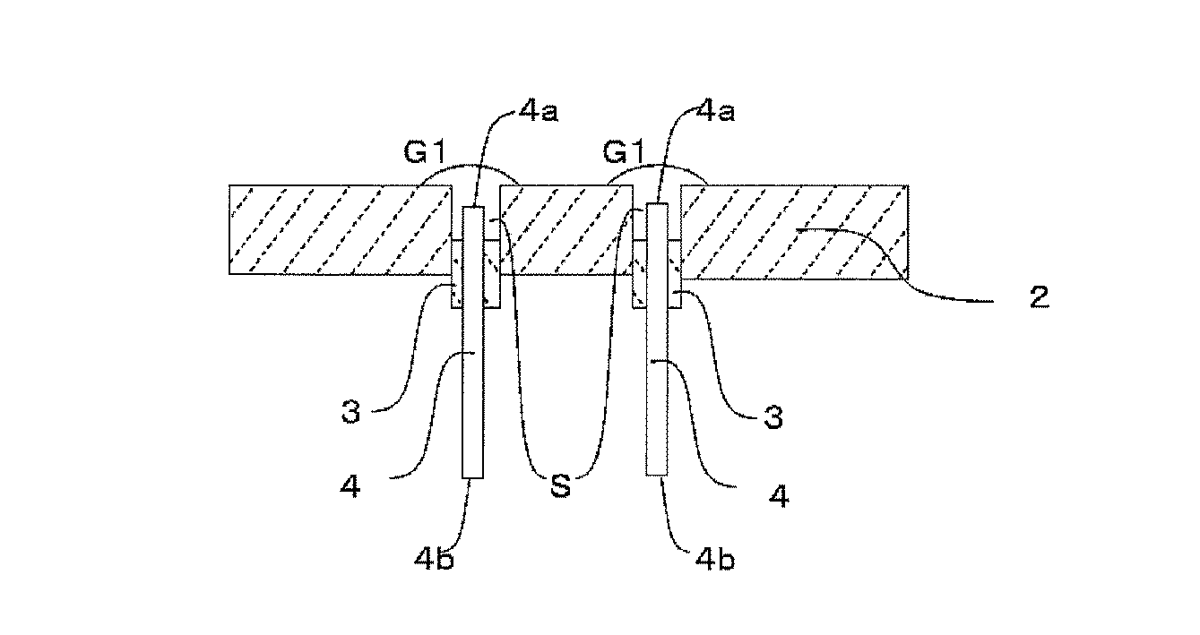
底壁2には、電極4を挿入するための貫通穴が形成されている。貫通穴は、電極を保持する電極ホルダ3をはめ込むのに適切な大きさであり、例えば直径50〜120mmの円形とすることができる。
底壁2の貫通穴には、電極ホルダ3が溶融槽1の内側の底面より下方に位置して空間Sを形成するように設置されている。底壁2の下面は外気によって冷やされているが、底壁2の上面は高温のガラス融液に接している。電極ホルダ3が高温のガラス融液G1、G2との接触によって侵食されるのを避けるため、電極ホルダ3は底壁2の貫通穴内に収容されている。電極ホルダ3の上面の位置は、溶融槽1の内側の底面より50〜150mm下であることが好ましい。電極ホルダ3の材質は、例えばステンレスなどの金属である。
A through hole for inserting the
In the through hole of the
電極ホルダ3の詳細な構造は図示しないが、電極ホルダ3は、電極4を適切な位置に保持するための保持手段と、水冷ジャケットなどの冷却手段を備えている。電極ホルダ3は、電極の上端部4aを底壁2の貫通穴内面と電極ホルダ3の上面とに囲まれた空間Sに位置するように保持することもできるし、電極の上端部4aを底壁2から突出させてガラス融液G2内に保持することもできるようになっている。電極4のガラス融液G2に挿入後の突出量は、例えば50〜100cm程度とすることができる。
電極4は棒状であって電極ホルダ3にはめ込まれ、電極の下端部4bはガラス融液G1、G2の外にあって外部電源に接続されている。電極の上端部4aをガラス融液G2中に挿入して通電すると、電極4間に存在するガラス融液G2の抵抗でジュール熱が発生し、ガラス融液G2が加熱される。図1には2本の電極4が示されているが、電極4は3本以上あってもよい。電極4は、例えば直径が40〜100mmの丸棒状とすることができる。
Although the detailed structure of the
The
底壁2の貫通穴内面と電極ホルダ3の上面とに囲まれた空間Sには、ガラス融液G1が充填されている。したがって、電極をガラス融液G2に挿入する前の状態では、電極の上端部4aが底壁2の貫通穴内面と電極ホルダ3の上面とに囲まれた空間Sに位置するように保持されることによって、電極の上端部4aがガラス融液G1で覆われる。
ガラス融液G1は、作業点が900℃以上1100℃以下の無アルカリガラスの融液である。
A space S surrounded by the inner surface of the through hole of the
The glass melt G1 is a non-alkali glass melt having a working point of 900 ° C. or higher and 1100 ° C. or lower.
溶融槽1は、高温のガラス融液G2を貯留してから電極4をガラス融液G2に挿入して使用される。溶融槽1にガラス融液G2が貯留されている状態において、底壁2の貫通穴内面と電極ホルダ3の上面とに囲まれた空間Sの温度は900〜1100℃程度である。第一のガラスは、作業点が900℃以上1100℃以下のガラスであるから、このときに適当な粘性を有する。第一のガラスの作業点が1100℃超であると、粘度が高くなりすぎるので電極4を挿入することは難しくなる。第一のガラスは、その作業点が900℃未満であると粘度が低くなりすぎて、底壁2の貫通穴と電極ホルダ3との隙間などから漏れ出す恐れがある。第一のガラスの作業点は、1000〜1080℃であることがより好ましい。
第一のガラスは、液相温度が1100℃以下であることが好ましい。液相温度が1100℃より高いガラスは、1100℃以下の温度域でガラス融液中に結晶が生じやすく、流動性が失われることがある。電極4は、底壁2の貫通穴内の空間に充填された第一のガラスの流動性が失われると、挿入が困難になるおそれや、挿入する際に大きな荷重が加わって壊れる等のおそれがある。
The
The first glass preferably has a liquidus temperature of 1100 ° C. or lower. Glass having a liquidus temperature higher than 1100 ° C. tends to produce crystals in the glass melt at a temperature range of 1100 ° C. or lower, and fluidity may be lost. If the fluidity of the first glass filled in the space in the through hole of the
なお、液相温度は、例えば温度傾斜炉を用いて熱処理したガラス試料を観察することによって求めることができる。本明細書では、ガラス試料を白金製の保持具上にセットし、定まった温度傾斜を保った炉中で熱処理した後、ガラス中に成長した結晶を顕微鏡で観察して、結晶の発生開始時点のガラス温度を液相温度としている。簡便な方法としては、例えば1100℃に保った炉内に、白金容器に入れたガラス片を保持した後に結晶の有無を観察することで、液相温度が1100℃より高いか低いかを判断できる。 In addition, liquid phase temperature can be calculated | required by observing the glass sample heat-processed, for example using the temperature gradient furnace. In this specification, a glass sample is set on a platinum holder, and after heat treatment in a furnace maintained at a fixed temperature gradient, the crystal grown in the glass is observed with a microscope, and the start of crystal generation The glass temperature is the liquidus temperature. As a simple method, for example, it is possible to determine whether the liquidus temperature is higher or lower than 1100 ° C. by observing the presence or absence of crystals after holding a glass piece in a platinum container in a furnace kept at 1100 ° C. .
第一のガラスは、第二のガラスより比重が大きいことが好ましい。それによって、ガラス融液G1がガラス融液G2に混入することは防止できる。例えば、第二のガラスの比重が2.50である場合、第一のガラスの比重は、2.51以上であることが好ましく、2.60以上であることがより好ましい。すなわち、第二のガラスの比重は、第一のガラスの比重に対して、0.01以上大きいことが好ましく、0.1以上大きいことがより好ましい。
第一のガラスの組成については後述する。
The first glass preferably has a higher specific gravity than the second glass. Thereby, it is possible to prevent the glass melt G1 from being mixed into the glass melt G2. For example, when the specific gravity of the second glass is 2.50, the specific gravity of the first glass is preferably 2.51 or more, and more preferably 2.60 or more. That is, the specific gravity of the second glass is preferably greater than or equal to 0.01 and more preferably greater than or equal to 0.1 relative to the specific gravity of the first glass.
The composition of the first glass will be described later.
本発明の溶融槽の別の実施形態は、上部に高温の気相雰囲気を形成するための酸素バーナー及び/又はプラズマトーチと、前記高温の気相雰囲気中にガラスの原料を造粒した原料粒子を投入するための原料供給手段を備えることができる。この場合、酸素バーナー及び/又はプラズマトーチは、溶融槽の天井部に下向きに設置されることが好ましい。それによって、原料粒子は、高温の気相雰囲気中で溶解され、気相中で溶融ガラス粒子を形成することができる。図2は、その実施形態の一例を示す図である。溶融槽11の天井部には、下向きの酸素バーナー5が設けられている。図2の酸素バーナー5は、火炎を形成するためのノズルのほかに原料供給ノズルも備えているが、酸素バーナーと原料供給口とは別々に設けられてもよい。第二のガラスの原料粒子G20は、バーナー5の原料供給用ノズルから高温の火炎中に投入され、第二のガラスの溶融ガラス粒子G21となって溶融槽11に貯留される。
Another embodiment of the melting tank of the present invention includes an oxygen burner and / or a plasma torch for forming a high-temperature gas phase atmosphere at the top, and raw material particles obtained by granulating a glass raw material in the high-temperature gas phase atmosphere Can be provided with a raw material supply means. In this case, it is preferable that the oxygen burner and / or the plasma torch be installed downward on the ceiling of the melting tank. Thereby, the raw material particles can be dissolved in a high temperature gas phase atmosphere to form molten glass particles in the gas phase. FIG. 2 is a diagram illustrating an example of the embodiment. A downward oxygen burner 5 is provided on the ceiling of the
本発明の溶融槽の別の実施形態は、他の溶融槽からガラス融液が供給されるガラス流入口を有することができる。図3はその一例を示す図である。溶融槽12は他の溶融槽100と連なっている。原料供給口72から他の溶融槽100に投入された第二のガラスの原料は、他の溶融槽100の側壁部に設けられたバーナー52の熱で溶解されてガラス融液G2となり、ガラス流入口6から溶融槽12に流入する。溶融槽12に流入したガラス融液G2は、電極4を用いて加熱され、脱泡等して均質化される。
Another embodiment of the melting tank of the present invention may have a glass inlet to which glass melt is supplied from another melting tank. FIG. 3 is a diagram showing an example. The
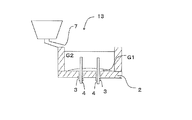
本発明の溶融槽の別の実施形態は、ガラス融液上に原料を投入する原料供給口を備えることができる。この場合、投入される原料は、酸化物、水酸化物、及び炭酸塩等の粉末であってもよく、それらを造粒した原料粒子であってもよく、それらの混合物であってもよい。図4はその一例を示す図である。溶融槽13の一端には原料供給口7がある。第二のガラスの原料は、原料供給口7から溶融槽13のガラス融液上に投入され、溶解されてガラス融液G2となる。溶融槽13は、加熱手段として底壁2に設置された電極4を備えているが、補助的な加熱手段としてバーナー等を備えることができる。溶融槽13は、電極4は補助的な加熱手段とし、バーナーを主たる加熱手段とすることもできる。なお、電極4を主たる加熱手段として用いる場合であっても、電極4をガラス融液G2に挿入する前にガラス融液G2を貯留するときには、上記バーナー等を用いてガラスの原料を溶解する。
Another embodiment of the melting tank of the present invention can include a raw material supply port for charging the raw material onto the glass melt. In this case, the raw material to be input may be a powder of oxide, hydroxide, carbonate, or the like, raw material particles obtained by granulating them, or a mixture thereof. FIG. 4 is a diagram showing an example. There is a raw material supply port 7 at one end of the
次に、本発明の電極の挿入方法をステップごとに説明する。
[電極を配置するステップ]
図5に示すように、電極4は、溶融槽1にガラス融液G2を貯留する前に、底壁2の貫通穴に挿入された電極の上端部4aが溶融槽1の内側の底面より10〜150mm下方に位置するように配置される。このとき、電極の上端部4aは、電極ホルダ3の上面よりも上方かつ底壁よりも下方に待機してあり、電極ホルダ3に備えられた冷却手段の効果で冷やされている。
Next, the electrode insertion method of the present invention will be described step by step.
[Step of placing electrodes]
As shown in FIG. 5, the
[ガラス融液G1を充填するステップ]
図5には、作業点が900℃以上1100℃以下の無アルカリガラスの融液であるガラス融液G1が、溶融槽1の底壁2に設けられた貫通穴の内面と電極ホルダ3の上面とで囲まれた空間Sに、充填された状態を示す。このとき電極の上端部4aはガラス融液G1で覆われている。貫通穴にガラス融液G1を充填することで、電極の挿入前に電極の酸化等の可能性がある部分をガラス融液G1で覆うことにより、電極の酸化等による劣化は防止できる。電極が劣化する可能性がある部分とは、ガラス融液G2に挿入する前に電極の温度が高くなる部分である。言い換えると、電極が劣化する可能性がある部分とは、電極の上部領域であり、電極を電極ホルダで保持する場合には電極と電極ホルダとの隙間や、電極を煉瓦で保持する場合には電極と煉瓦との隙間等の部分を含む。図5で2本の電極の上端部4aは、それぞれの空間Sにあるガラス融液G1で覆われているが、図4に見られるように複数の空間Sにあるガラス融液G1がつながった状態であってもよい。
[Step of filling glass melt G1]
In FIG. 5, a
ガラス融液G1を充填する方法は種々の方法を採用できる。例えば、ガラス融液G1は、他の溶融槽等で第一のガラスの原料を溶解して得られたガラス融液G1を、底壁2に設けられた貫通穴の内面と電極ホルダ3の上面とで囲まれた空間Sに注ぐ方法で充填してもよい。また、第一のガラスの原料は、溶融槽1内で溶解してもよい。電極4の酸化による劣化を防止できること、及び作業が簡単であることから、ガラス融液を充填するステップは、第一のガラスのカレットを前記貫通穴の内部又は周囲に配置し(カレットを配置するステップ)、前記配置したカレットを溶融してガラス融液G1にすること(カレットを溶融するステップ)が好ましい。
Various methods can be adopted as the method of filling the glass melt G1. For example, the glass melt G1 is obtained by dissolving the glass melt G1 obtained by melting the first glass raw material in another melting tank or the like with the inner surface of the through hole provided in the
[第一のガラスのカレットを配置するステップ]
貫通穴の内部又は周囲には、第一のガラスのカレットが配置される。第一のガラスのカレットは、後述のカレットを溶融するステップにおいて、電極の上端部4aをガラス融液G1で覆うに足りる充分量を適切な位置に配置する。また、第一のガラスのカレットは、底壁2の貫通穴付近の表面に配置してもよく、貫通穴を塞ぐように配置してもよい。
第一のガラスのカレットは、小さく砕いて底壁2の貫通穴の空間、すなわち貫通穴内面と電極ホルダ3の上面とに囲まれた空間Sに充填されるように配置することが好ましい。例えば、長径が1mm〜20mm程度の粒状に砕いた第一のガラスのカレットを空間S内に充填することは、電極の上端部4aが、カレットの溶融後にガラス融液G1によって速やかに覆われるので特に好ましい。砕いたカレットを空間Sに充填した上に平坦な板状のカレットを載せることは、電極の上端部4aから高温の空気を遮断できるのでより好ましい。
[Step of placing the first glass cullet]
A first glass cullet is disposed inside or around the through hole. The first glass cullet is disposed at an appropriate position in a sufficient amount to cover the
The first glass cullet is preferably crushed and disposed so as to fill the space of the through hole in the
[第一のガラスのカレットを溶融するステップ]
底壁の貫通穴に充填された第一のガラスのカレットは、溶融槽1の側壁や天井等に設けられた加熱用バーナーなどを用いて溶融槽の温度を上げると、溶融されてガラス融液G1となる。溶融槽1内の大部分が1500℃程度の高温になっている場合でも、底壁2の貫通穴内部は、電極4が酸化されるのを防止するために電極ホルダ3に備えられた冷却手段等によって、例えば500℃〜800℃程度に冷やされている。第一のガラスは、作業点が900℃以上1100℃以下のガラスであるから、この温度域である程度の流動性を有し、溶融状態になる。
[Step of melting first glass cullet]
The first glass cullet filled in the through hole of the bottom wall is melted when the temperature of the melting tank is increased using a heating burner provided on the side wall or the ceiling of the
[ガラス融液G2を貯留するステップ]
ガラス融液G1を空間Sに充填した後は、ガラス融液G2を溶融槽1に貯留する。このときガラス融液G2の温度は、例えば1500℃以上になっている。ガラス融液G2については後述する。
図6は、電極をガラス融液G2に挿入する前で、ガラス融液G2が貯留された状態を表した溶融槽1の断面図である。ガラス融液G2を貯留する方法としては、例えば以下の方法が採用できる。
[Step of storing glass melt G2]
After the glass melt G1 is filled into the space S, the glass melt G2 is stored in the
FIG. 6 is a cross-sectional view of the
ガラス融液G2の貯留方法の一例としては、第二のガラスの原料を造粒した原料粒子を酸素燃焼炎中及び/又は熱プラズマ中に投入して溶解することにより形成した溶融ガラス粒子を堆積する方法が挙げられる。この方法では、溶融槽1の上部に原料粒子を溶融するためのバーナーを設置し、酸素燃焼炎中に投入した原料粒子を気相中で溶融ガラス粒子として溶融槽1に落下させ堆積させる方法が採用できる。
As an example of a method for storing glass melt G2, molten glass particles formed by melting raw material particles obtained by granulating the second glass raw material in an oxyfuel flame and / or thermal plasma are deposited. The method of doing is mentioned. In this method, there is a method in which a burner for melting raw material particles is installed in the upper part of the
例えば、図2の溶融槽11では、天井に下向きの酸素バーナー5が設けられている。酸素バーナー5は、火炎を形成するためのノズルのほかに原料を供給するノズルを備えている。第二のガラスの原料粒子G20は、酸素バーナー5の原料供給用ノズルから気流搬送によって高温の酸素燃焼炎中に投入される。第二のガラスの原料粒子G20は、酸化物や炭酸塩等の原料の混合物が集合したものからなり、例えば1mm程度以下の粒子状に造粒されたものである。第二のガラスの原料粒子G20は、酸素バーナー5を燃焼させることによって形成された高温の気相中で溶解し、第二のガラスの溶融ガラス粒子G21となる。第二のガラスの溶融ガラス粒子G21は、電極の上端部4aが底壁2内に留まっている状態の溶融槽11に堆積して貯留される。
For example, in the
また、ガラス融液G2の貯留方法の別の例としては、溶融槽1の外(例えば他の溶融槽)で第二のガラスの原料を溶解してから、得られたガラス融液G2を溶融槽1に流入させることによりガラス融液G2を貯留する方法が挙げられる。この場合、溶融槽1は、ガラス融液G2を均質化するための槽として利用できる。
例えば、図3の溶融槽12では、第二のガラスの原料が原料供給口72から他の溶融槽100に投入される。第二のガラスの原料は、他の溶融槽100の側壁部に設けられたバーナー52の熱で溶解してガラス融液G2を形成する。得られたガラス融液G2は、ガラス流入口6から、電極の上端部4aが底壁2内に留まっている状態の溶融槽12に流入して貯留される。
Another example of the method for storing the glass melt G2 is to melt the glass melt G2 obtained after melting the raw material of the second glass outside the melt tank 1 (for example, another melt tank). The method of storing glass melt G2 by making it flow in the
For example, in the
前記ガラス融液G2の貯留方法のさらに別の例としては、第二のガラスの原料を溶融槽1に投入して溶解することによってガラス融液G2を貯留する方法が挙げられる。この方法では、第二のガラスの原料を混合して溶融槽1に投入した後、溶融槽1の側壁や天井に設けられたバーナーで溶解することができる。
例えば、図4の溶融槽13では、第二のガラスの原料を原料供給口7から電極の上端部4aが底壁2内に留まっている状態の溶融槽13に投入し、バーナー等で加熱して溶解することによりガラス融液G2を貯留する。
Still another example of the method for storing the glass melt G2 is a method for storing the glass melt G2 by charging the raw material of the second glass into the
For example, in the
[電極を挿入するステップ]
ガラス融液G2の貯留後、電極の上端部4aは、ガラス融液G1を貫通してガラス融液G2に入るように電極4を押し上げて挿入される。このときガラス融液G2が貯留された溶融槽1内の大部分は1500℃程度の高温になっているが、底壁2の貫通穴内部は、電極ホルダ3に備えられた冷却手段等によって、例えば500℃〜800℃程度に冷やされている。電極ホルダ3の水冷を数分間中止するなどの方法で、電極の上端部4aを覆っているガラス融液G1の温度を900〜1100℃程度まで上げると、ガラス融液G1は、粘度が下がって適度に流動するようになる。したがって、電極4は、大きな加重を加えなくても押し上げることが可能になる。さらに、電極4は、ガラス融液G2がバーナー等で加熱されて高温になっているので、大きな加重を加えなくても挿入して、ガラス融液G2内に突出させることができる。電極の上端部4aの位置は、ガラス融液G2を加熱するために適切な高さとする。
電極の上端部4aをガラス融液G2に挿入した後、電極間に通電するとガラス中に電流が流れてジュール熱が発生し、ガラス融液G2が加熱される。
[Step of inserting electrode]
After storing the glass melt G2, the
After the
[第一のガラス]
第一のガラスは無アルカリガラスである。すなわち、第一のガラスは、Na2O、K2O、及びLi2O等のアルカリ金属成分を不純物レベル以上には含有しない。アルカリ金属成分は、含有するとしてもガラス中の合計が1モル%以下である。アルカリ金属成分を含有するガラスの場合には、溶融槽1の底壁2を構成する煉瓦内にアルカリ金属成分が侵入して煉瓦の電気抵抗率を低下させるおそれがある。煉瓦の電気抵抗率が低下するとガラス融液G2の中を流れるべき電流が煉瓦内に流れ、ガラス融液の加熱効率は低下する。また、煉瓦内に電流が流れると、煉瓦は異常な加熱を起こし、溶融する恐れがある。
第一のガラスは、酸化物基準のモル%表示でSiO2を52〜64%、B2O3を3〜25%、Al2O3を2〜10%、MgOを0〜11%、CaOを0〜11%、並びにSrO及びBaOから選ばれるいずれか一以上の酸化物を総量で2〜30%、含有することが好ましい。このようなガラスは、無アルカリガラスでありながらソーダライムガラスと同程度の低い粘性を有し、しかも液相温度が低いので結晶化が生じにくく、電極を酸化させにくい。
[First glass]
The first glass is alkali-free glass. That is, the first glass does not contain alkali metal components such as Na 2 O, K 2 O, and Li 2 O above the impurity level. Even if it contains an alkali metal component, the total in glass is 1 mol% or less. In the case of glass containing an alkali metal component, the alkali metal component may enter the brick constituting the
The first glass is SiO 2 52-64%, B 2 O 3 3-25%, Al 2 O 3 2-10%, MgO 0-11%, CaO, expressed as mol% on oxide basis. 0 to 11%, and any one or more oxides selected from SrO and BaO are preferably contained in a total amount of 2 to 30%. Such a glass is alkali-free glass but has a viscosity as low as soda lime glass, and since the liquidus temperature is low, crystallization hardly occurs and the electrode is not easily oxidized.
以下、この好ましいガラスの組成について「モル%」を単に「%」と表記して説明する。
SiO2は、ガラスのネットワークを形成する酸化物であり必須である。SiO2の含有量は、52%以上であることが好ましく、54%以上であることがより好ましい。また、SiO2の含有量は、64%以下であることが、好ましく、62%以下であることがより好ましい。SiO2の含有量は、上記の下限値以上とすればガラスが安定で失透しにくくなり、上記の上限値以下とすればガラス化に要する温度が高くなりすぎないからである。
Hereinafter, the composition of this preferable glass will be described by simply describing “mol%” as “%”.
SiO 2 is an oxide that forms a glass network and is essential. The content of SiO 2 is preferably 52% or more, and more preferably 54% or more. Further, the content of SiO 2 is preferably 64% or less, and more preferably 62% or less. This is because if the content of SiO 2 is not less than the above lower limit value, the glass is stable and hardly devitrified, and if it is not more than the above upper limit value, the temperature required for vitrification does not become too high.
Al2O3は、ガラスを安定化する成分であり2%以上含有することが好ましい。Al2O3は、2%以上であるとガラスを安定化する効果が高いので好ましい。Al2O3は、10%以下であると、ガラス化に高温を要せず、また液相温度が高くなりすぎないので好ましい。
SiO2とAl2O3はガラスの作業点を高くする成分である。作業点を1100℃以下にするためには、SiO2及びAl2O3の含有量の合計は、68%以下であることが好ましく、66%以下であることがより好ましい。作業点を900℃以上にするためには、SiO2とAl2O3の含有量の合計は57%以上であることが好ましく、60%以上であることがより好ましい。SiO2とAl2O3の含有量の合計を前記範囲とすることで、好ましい作業点を有するガラスが得られる。SiO2とAl2O3の含有量の合計は、60〜66%であることがより好ましい。
Al 2 O 3 is a component that stabilizes the glass, and is preferably contained in an amount of 2% or more. Al 2 O 3 is preferably 2% or more because the effect of stabilizing the glass is high. When Al 2 O 3 is 10% or less, vitrification does not require a high temperature and the liquidus temperature does not become too high, which is preferable.
SiO 2 and Al 2 O 3 are components that increase the working point of glass. In order to set the working point to 1100 ° C. or lower, the total content of SiO 2 and Al 2 O 3 is preferably 68% or lower, and more preferably 66% or lower. In order to set the working point to 900 ° C. or higher, the total content of SiO 2 and Al 2 O 3 is preferably 57% or higher, and more preferably 60% or higher. By setting the total content of SiO 2 and Al 2 O 3 in the above range, a glass having a preferable work point can be obtained. The total content of SiO 2 and Al 2 O 3 is more preferably 60 to 66%.
B2O3は、ガラスのネットワークを形成する成分であり、粘性を下げる成分である。B2O3の含有量は、3%以上であることが好ましく、5%以上であることが、ガラスの粘性を低くできるので、より好ましい。B2O3の含有量は、25%以下であることが好ましく、20%以下であることが、ガラスの耐酸性や耐水性を高くできるので、より好ましい。 B 2 O 3 is a component that forms a glass network and is a component that lowers the viscosity. The content of B 2 O 3 is preferably 3% or more, and more preferably 5% or more because the viscosity of the glass can be lowered. The content of B 2 O 3 is preferably 25% or less, and more preferably 20% or less because the acid resistance and water resistance of the glass can be increased.
MgO、CaO、SrO及びBaOは、いずれもガラスの安定性を増す任意成分であり、粘性を下げる成分であり、合計で10〜40%含有することが好ましい。ガラスの安定性を高めるためには、いずれか2種以上を含有することがより好ましい。液相温度を下げるためにはMgO、CaO、SrO及びBaOの総量は40%以下であることが好ましく、30%以下であることがより好ましい。ガラスの粘性を下げるためには、MgO、CaO、SrO及びBaOの総量は10%以上であることが好ましく、15%以上であることがより好ましく、20%以上であることがさらに好ましい。
MgOを含有する場合、ガラスの失透性の観点から、その含有量は1〜11%であることがより好ましい。
CaOを含有する場合、ガラスの失透性の観点から、その含有量は1〜11%であることがより好ましい。
SrO及びBaOは、ガラスの粘性を下げる効果が大きく、比重を大きくする成分である。SrO及びBaOから選ばれるいずれか一以上の酸化物の総量は、粘性及び比重の観点から2%以上であることが好ましく、5%以上であることがより好ましい。SrO及びBaOから選ばれるいずれか一以上の酸化物の総量は、ガラスの失透性の観点から30%以下であることが好ましく、25%以下であることがより好ましい。
MgO, CaO, SrO, and BaO are all optional components that increase the stability of the glass and are components that lower the viscosity, and are preferably contained in a total of 10 to 40%. In order to improve the stability of the glass, it is more preferable to contain any two or more of them. In order to lower the liquidus temperature, the total amount of MgO, CaO, SrO and BaO is preferably 40% or less, and more preferably 30% or less. In order to reduce the viscosity of the glass, the total amount of MgO, CaO, SrO and BaO is preferably 10% or more, more preferably 15% or more, and further preferably 20% or more.
When it contains MgO, it is more preferable that the content is 1 to 11% from a viewpoint of the devitrification property of glass.
When it contains CaO, it is more preferable that the content is 1 to 11% from a viewpoint of the devitrification property of glass.
SrO and BaO are components that greatly increase the viscosity of the glass and increase the specific gravity. The total amount of any one or more oxides selected from SrO and BaO is preferably 2% or more, more preferably 5% or more from the viewpoint of viscosity and specific gravity. The total amount of one or more oxides selected from SrO and BaO is preferably 30% or less and more preferably 25% or less from the viewpoint of devitrification of the glass.
第一のガラスは、上記のほかにZnO、ZrO2、TiO2、La2O3、及びP2O5から選ばれる一以上の成分を適宜含有することができる。これらの総量は、10%以下であることが好ましく、5%以下であることがより好ましい。
第一のガラスは、As2O3、Sb2O3、PbO、及びBi2O3を含有しないことが好ましい。これらの成分は、電極を酸化する傾向が強い。
In addition to the above, the first glass can appropriately contain one or more components selected from ZnO, ZrO 2 , TiO 2 , La 2 O 3 , and P 2 O 5 . The total amount of these is preferably 10% or less, and more preferably 5% or less.
The first glass preferably does not contain As 2 O 3 , Sb 2 O 3 , PbO, and Bi 2 O 3 . These components have a strong tendency to oxidize the electrode.
[第二のガラス]
第二のガラスは、作業点が1100℃超のガラスである。そのようなガラスは、歪点も高いことから耐熱性の高いガラスとして有用である。
第二のガラスは、酸化物基準のモル%表示でSiO2を60〜75%、B2O3を0〜20%、Al2O3を5〜20%、MgO、CaO、SrO及びBaOから選ばれるいずれか一以上の酸化物を総量で5〜25%、並びにSiO2及びAl2O3を合計で68%超、含有する無アルカリガラスであることが好ましい。このような組成のガラスは、歪点が高く、熱膨張係数や、耐酸性、その他の特性の点から液晶ディスプレイパネル用等に用いる基板ガラスに適している。
[Second glass]
The second glass is a glass having a working point exceeding 1100 ° C. Such a glass is useful as a glass having high heat resistance because of its high strain point.
The second glass is a SiO 2 60 to 75% by mol% based on oxides,
このガラス組成について説明する。
SiO2は、ガラスのネットワークを形成する酸化物であり必須である。SiO2の含有量は、60%以上であることが好ましく、65%以上であることが、ガラスの歪点を高くできることから、より好ましい。SiO2の含有量は75%以下であることが好ましく、70%以下であることが、ガラス化に要する温度を低くできることから、より好ましい。
Al2O3はSiO2とともに歪点を高くする成分であり、5%以上含有することによって歪点を高くすることができる。Al2O3の含有量は、20%以下であるとガラスが不安定になりにくい。
This glass composition will be described.
SiO 2 is an oxide that forms a glass network and is essential. The content of SiO 2 is preferably 60% or more, and more preferably 65% or more because the strain point of the glass can be increased. The content of SiO 2 is preferably 75% or less, and more preferably 70% or less because the temperature required for vitrification can be lowered.
Al 2 O 3 is a component that increases the strain point together with SiO 2 , and the content of 5% or more can increase the strain point. If the content of Al 2 O 3 is 20% or less, the glass is less likely to become unstable.
ガラスの歪点を高くするためには、SiO2とAl2O3の含有量の合計は、68%超であることが好ましく、70%以上であることがより好ましい。ガラスの製造しやすさの観点からは、SiO2とAl2O3の含有量の合計は、85%以下であることが好ましく、80%以下であることがより好ましい。
B2O3はガラスの粘性を下げる任意成分である。ガラスの耐酸性を高くするためには、B2O3の含有量は、20%以下であることが好ましく、15%以下であることがより好ましい。B2O3を含有する場合、ガラスの粘性の観点から、含有量は1%以上であることが好ましく、5%以上であることがより好ましい。
MgO、CaO、SrO及びBaOはいずれもガラスの粘性を下げる任意成分であり、ガラスの粘性を下げるためには、いずれか一以上の酸化物を総量で5%以上含有することが好ましく、10%以上含有することがより好ましい。MgO、CaO、SrO及びBaOの総量は、ガラスの安定性の観点で、25%以下であることが好ましく、20%以下であることがより好ましい。
In order to increase the strain point of the glass, the total content of SiO 2 and Al 2 O 3 is preferably more than 68%, and more preferably 70% or more. From the viewpoint of easy manufacturing of glass, the total content of SiO 2 and Al 2 O 3 is preferably 85% or less, and more preferably 80% or less.
B 2 O 3 is an optional component that lowers the viscosity of the glass. In order to increase the acid resistance of the glass, the content of B 2 O 3 is preferably 20% or less, and more preferably 15% or less. When B 2 O 3 is contained, the content is preferably 1% or more, and more preferably 5% or more, from the viewpoint of the viscosity of the glass.
MgO, CaO, SrO and BaO are all optional components that lower the viscosity of the glass, and in order to lower the viscosity of the glass, it is preferable that any one or more oxides are contained in a total amount of 5% or more. It is more preferable to contain above. The total amount of MgO, CaO, SrO and BaO is preferably 25% or less, and more preferably 20% or less, from the viewpoint of glass stability.
第二のガラスは、上記のほかにZnO、CuO、CoO、Fe2O3、ZrO2、TiO2、La2O3、及びP2O5から選ばれる一以上の成分を含有してもよい。これらの総量は、5%以下であることが好ましい。 In addition to the above, the second glass may contain one or more components selected from ZnO, CuO, CoO, Fe 2 O 3 , ZrO 2 , TiO 2 , La 2 O 3 , and P 2 O 5. . The total amount of these is preferably 5% or less.
[ガラス製品の製造方法]
本発明のガラス製品の製造方法の実施形態は、第二のガラスからなるガラス製品を製造する方法であり、前述の電極の挿入方法を用いて、ガラス融液G2を加熱するステップを有する。
図7は、一般的なガラス製品の製造方法の例を表すフロー図である。ガラス製品は、ガラスの原料を溶解してガラス融液を得るステップS01、得られたガラス融液G2を均質化するステップS02、ガラス融液G2を板状などに成形するステップS03、成形した成形物を徐冷するステップS04を経て得ることができる。
ガラス融液G2を加熱するステップは、原料を溶融してガラス融液G2を得るステップS01、及び得られたガラス融液G2を均質化するステップS02の一方又は両方のステップで、本発明の電極の挿入方法によって挿入した電極を用いてガラス融液G2を加熱することが好ましい。
[Glass product manufacturing method]
Embodiment of the manufacturing method of the glass product of this invention is a method of manufacturing the glass product which consists of 2nd glass, and has the step which heats the glass melt G2 using the above-mentioned electrode insertion method.
FIG. 7 is a flowchart showing an example of a general glass product manufacturing method. The glass product is obtained by melting a glass raw material to obtain a glass melt, step S01 for homogenizing the obtained glass melt G2, step S03 for shaping the glass melt G2 into a plate shape, and the like. It can be obtained through step S04 of slowly cooling the object.
The step of heating the glass melt G2 includes one or both of a step S01 for melting the raw material to obtain the glass melt G2 and a step S02 for homogenizing the obtained glass melt G2. It is preferable to heat the glass melt G2 using the electrode inserted by the insertion method.
本発明の電極の挿入方法で挿入された電極を用いてガラス融液G2を得るステップS01を実施する場合、第二のガラスの原料は、本発明の電極の挿入方法によって電極を挿入した溶融槽1に投入され溶解される。例えば、図4において、第二のガラス原料は、原料供給口7から溶融槽13内のガラス融液G2上に投入され、本発明の電極の挿入方法によって挿入した電極4を用いて溶解される。ガラス融液G2を得るステップS01で本発明の電極の挿入方法を用いる場合には、バーナーなどを主たる加熱手段として原料を溶解し、電極4を補助的な加熱手段として利用してもよい。
When the step S01 for obtaining the glass melt G2 using the electrode inserted by the electrode insertion method of the present invention is performed, the second glass material is a melting tank in which the electrode is inserted by the electrode insertion method of the present invention. 1 is dissolved. For example, in FIG. 4, the second glass raw material is charged on the glass melt G2 in the
本発明の電極の挿入方法で挿入された電極を用いてガラス融液G2を均質化するステップS02を実施する場合、ガラス融液G2を得るステップS01は、任意の方法によって行うことができる。すなわち、ガラス融液G2は、他の溶融槽等を用いて任意の方法で原料を溶解して形成し、本発明の電極の挿入方法によって電極を挿入した溶融槽1に流し入れて均質化することができる。この均質化をする場合には、他の加熱手段を適宜併用することができる。例えば、図3では、ガラス融液G2は、他の溶融槽100に原料供給口72から第二のガラスの原料を投入し、他の溶融槽100の側壁部に設けられたバーナー52の熱で前記原料を溶解して形成する。得られたガラス融液G2は、ガラス流入口6から溶融槽12に流し入れ、本発明の電極の挿入方法で挿入した電極4を用いて加熱し、脱泡等の均質化することができる。
When step S02 for homogenizing glass melt G2 using the electrode inserted by the electrode insertion method of the present invention is performed, step S01 for obtaining glass melt G2 can be performed by any method. That is, the glass melt G2 is formed by melting the raw material by an arbitrary method using another melting tank or the like, and is poured into the
また、第二のガラスの原料粒子は、酸素燃焼炎中及び/又は熱プラズマ中に投入して溶解することによって溶融ガラス粒子を形成し、得られた溶融ガラス粒子は、本発明の電極の挿入方法によって電極を挿入した溶融槽に供給しながら均質化してもよい。例えば、図2において溶融槽11の天井には下向きの酸素バーナー5が設けられ、酸素バーナー5は、酸素燃焼炎を形成するためのノズルの他にガラスの原料粒子を供給するノズルを備えている。第二のガラスの原料粒子G20は、気流搬送によって酸素バーナー5の原料供給用ノズルから高温の酸素燃焼炎中に投入される。第二のガラスの原料粒子G20は、酸化物や炭酸塩等の原料の混合物からなり、例えば1mm程度以下の粒子状に造粒されたものである。第二のガラスの原料粒子G20は、酸素バーナー5を燃焼させることによって形成された高温の気相中で溶解し、第二のガラスの溶融ガラス粒子G21となって溶融槽11に落下する。得られた第二のガラスの溶融ガラス粒子G21は、溶融槽11内に貯留し、本発明の電極の挿入方法によって挿入した電極4を用いて加熱して均質化することができる。
ガラス融液G2を板状などに成形するステップS03及び成形物を徐冷するステップS04は、公知の方法で行うことができる。
The second glass raw material particles are melted by being introduced into an oxyfuel flame and / or thermal plasma to form molten glass particles, and the obtained molten glass particles are inserted into the electrode of the present invention. You may homogenize, supplying to the melting tank which inserted the electrode by the method. For example, in FIG. 2, a downward oxygen burner 5 is provided on the ceiling of the
The step S03 for forming the glass melt G2 into a plate shape and the step S04 for gradually cooling the formed product can be performed by a known method.
表1、2は、第一のガラス及び第二のガラスの例について、酸化物基準のモル%で表示したガラス組成及び物性値を示したものである。例1〜10は第一のガラスの例、例11及び12は比較例、例13は第二のガラスの実施例であり第一のガラスの比較例でもある。
ガラスの原料としては、一般的に使用されている酸化物、炭酸塩、及び水酸化物等を使用し、表1、2のSiO2からNa2Oまでの欄に示した組成となるように調合及び混合した。混合した原料を、白金坩堝に入れ、間接抵抗加熱式の電気炉を用いて、例1、2、及び12については1500℃、並びに例13については1600℃に加熱して溶融した。例1、2は第一のガラスの例である。例12はソーダライムガラスである。
Tables 1 and 2 show the glass compositions and physical property values expressed in mol% based on oxides for the examples of the first glass and the second glass. Examples 1 to 10 are examples of the first glass, Examples 11 and 12 are comparative examples, Example 13 is an example of the second glass, and is also a comparative example of the first glass.
As raw materials for glass, commonly used oxides, carbonates, hydroxides, etc. are used so that the composition shown in the columns from SiO 2 to Na 2 O in Tables 1 and 2 is obtained. Formulated and mixed. The mixed raw materials were put into a platinum crucible and melted by heating to 1500 ° C. for Examples 1, 2, and 12 and 1600 ° C. for Example 13 using an indirect resistance heating type electric furnace. Examples 1 and 2 are examples of the first glass. Example 12 is soda lime glass.
得られた溶融ガラスからカレットと物性測定用のガラスブロックを得て、各ガラスの作業点を回転粘度計で測定した。結果を表1の作業点欄に示す。
また、温度傾斜炉を用いる方法で液相温度を測定した。結果を表1の液相温度欄に示す。さらに、「JISZ8807−1976固体比重測定方法4.液中でひょう量する測定方法」を準用して比重を測定した結果を表1の比重欄に示す。
ガラスの物性値は、例1、2、12、及び13については実測値、例3〜11についてはガラス組成からの推定値である。
A cullet and a glass block for measuring physical properties were obtained from the obtained molten glass, and the working point of each glass was measured with a rotational viscometer. The results are shown in the work point column of Table 1.
Further, the liquidus temperature was measured by a method using a temperature gradient furnace. The results are shown in the liquid phase temperature column of Table 1. Furthermore, the specific gravity column of Table 1 shows the result of measuring the specific gravity by applying “JISZ 8807-1976 Solid Specific
The physical property values of the glass are actually measured values for Examples 1, 2, 12, and 13, and estimated values from the glass composition for Examples 3 to 11.
例1、2、12、及び13の組成のガラスについては、その効果を評価するため、以下の実験を行った。実験では、まず、高ジルコニア質電鋳煉瓦(商品名ZB−X9540:AGCセラミックス社製)に直径70mmの貫通穴を2箇所設けて電極ホルダをはめ込んだものを溶融槽の底壁に設置し、直径48mmのモリブデン棒を電極として電極ホルダに挿入した。
次に、実験では、電極の上端が溶融槽の底面より20mm下になるように調整してから、第一のガラスとして例1のガラスカレットを1.5kgずつ、底壁の各貫通穴の上部に充填し、電極ホルダを水冷しながら、溶融槽の底面から50mm上の位置で測定された温度が1600℃になるまで加熱した。これによって、第一のガラスカレットは溶融した。このとき貫通穴の内部は電極ホルダの水冷機能によって冷却されているが、500〜800℃程度になっていると推定される。
さらに、実験では、第二のガラスとして1600℃で溶融された例13のガラス融液を溶融槽に貯留した後、電極ホルダの冷却を5分間停止し、電極を上方に押し込んだところ、所定の高さ(500mm)まで問題なく挿入できた。その後2ヶ月間、溶融槽の運転を継続したところ、ガラス融液の温度は常に適正に保持され、高品質のガラス製品を製造することができた。
For the glasses having the compositions of Examples 1, 2, 12, and 13, the following experiment was conducted in order to evaluate the effect. In the experiment, first, a high zirconia electroformed brick (trade name ZB-X9540: manufactured by AGC Ceramics) was provided with two through holes with a diameter of 70 mm and fitted with an electrode holder on the bottom wall of the melting tank, A molybdenum rod having a diameter of 48 mm was inserted as an electrode into the electrode holder.
Next, in the experiment, after adjusting the upper end of the electrode to be 20 mm below the bottom of the melting tank, 1.5 kg each of the glass cullet of Example 1 as the first glass, the upper part of each through hole in the bottom wall The electrode holder was heated until the temperature measured at a position 50 mm above the bottom of the melting tank reached 1600 ° C. while cooling the electrode holder with water. This melted the first glass cullet. At this time, the inside of the through hole is cooled by the water cooling function of the electrode holder, but is estimated to be about 500 to 800 ° C.
Further, in the experiment, after the glass melt of Example 13 melted at 1600 ° C. as the second glass was stored in the melting tank, the cooling of the electrode holder was stopped for 5 minutes, and the electrode was pushed upward. Insertion was possible up to a height (500 mm) without any problems. When the operation of the melting tank was continued for 2 months thereafter, the temperature of the glass melt was always kept properly, and a high-quality glass product could be produced.
別の実験として第一のガラスとして例1のガラスのカレットのかわりに例12のガラスのカレットを用いた場合は、電極を挿入するまでは問題がなかったが、溶融槽の運転を約1ヶ月継続した後にガラス融液の温度が低下する問題が発生し、ガラス製品の品質が不安定になった。
また、第一のガラスとして例1のガラスのカレットのかわりに例13のガラスのカレットを用いた場合は、電極ホルダの冷却を5分間停止して温度を上げてもガラスの粘性が高すぎて電極を挿入することができなかった。第一のガラスとして例2〜10のガラスを用いて同様の実験をした場合は、アルカリ金属酸化物を含有せず、好ましい粘性を有していることから、例1のガラスを用いた場合と同様の効果が予想できる。
さらに、例1〜10のガラスは、いずれも例13のガラスより比重が大きいので、第二のガラスとして例13のガラスの融液を貯留した場合に第一のガラスと第二のガラスの混合が生じにくいと考えられる。
例11のガラスは、CaO含有量が高く、液相温度が高いので電極を挿入する際にガラスが結晶化する恐れがあり、電極が破損する恐れがある。
In another experiment, when the glass cullet of Example 12 was used instead of the glass cullet of Example 1 as the first glass, there was no problem until the electrode was inserted. After continuing, there was a problem that the temperature of the glass melt decreased, and the quality of the glass product became unstable.
In addition, when the glass cullet of Example 13 was used as the first glass instead of the glass cullet of Example 1, the viscosity of the glass was too high even when the temperature of the electrode holder was stopped for 5 minutes and the temperature was raised. The electrode could not be inserted. When the same experiment was performed using the glass of Examples 2 to 10 as the first glass, the glass had the preferable viscosity without containing an alkali metal oxide. Similar effects can be expected.
Furthermore, since the specific gravity of the glasses of Examples 1 to 10 is larger than that of the glass of Example 13, when the melt of the glass of Example 13 is stored as the second glass, the first glass and the second glass are mixed. Is considered to be difficult to occur.
Since the glass of Example 11 has a high CaO content and a high liquidus temperature, the glass may crystallize when the electrode is inserted, and the electrode may be damaged.
本発明は、無アルカリガラスなどの高歪点ガラスの製造に適用可能である。 The present invention is applicable to the production of high strain point glass such as alkali-free glass.
1、11、12、13:溶融槽
2 :底壁
3 :電極ホルダ
4 :電極
4a :電極の上端部
4b :電極の下端部
5、52 :バーナー
6 :ガラス流入口
7、72 :原料供給口
100 :他の溶融槽
G1 :第一のガラスの融液
G2 :第二のガラスの融液
G20 :第二のガラスの原料粒子
G21 :第二のガラスの溶融ガラス粒子
DESCRIPTION OF
Claims (15)
ガラス溶融槽の煉瓦製の底壁にある貫通穴に電極の上端が該底壁の溶融ガラス側表面よりも10〜150mm下方になる位置に該電極を配置するステップと、
前記貫通穴に作業点が900℃以上1100℃以下の無アルカリガラスである第一のガラスの融液を充填するステップと、
前記ガラス溶融槽に作業点が1100℃超の第二のガラスの融液を貯留するステップと、
前記電極の上端が前記第一のガラスの融液を貫通し前記第二のガラスの融液に入るように該電極を挿入するステップと、
を有する電極の挿入方法。 A method for inserting an electrode of a glass melting tank,
Disposing the electrode at a position where the upper end of the electrode is 10 to 150 mm below the molten glass side surface of the bottom wall in a through hole in the brick bottom wall of the glass melting tank;
Filling the through hole with a melt of a first glass which is an alkali-free glass having a working point of 900 ° C. or higher and 1100 ° C. or lower;
Storing a second glass melt having a work point of over 1100 ° C. in the glass melting tank;
Inserting the electrode so that the upper end of the electrode penetrates the melt of the first glass and enters the melt of the second glass;
An electrode insertion method comprising:
前記第二のガラスの融液を成形するステップと、
前記成形された成形物を徐冷するステップと、
を含むガラス製品の製造方法。 Inserting the electrode into the glass melting tank by the electrode insertion method according to any one of claims 1 to 7, and heating the melt of the second glass with the electrode;
Forming a melt of the second glass;
Gradually cooling the molded article,
A method for producing glass products including
貫通穴を有する煉瓦製の底壁と、該底壁の貫通穴に挿入された電極と、前記貫通穴に充填された第一のガラスと、を含み、
前記第一のガラスは、作業点が900℃以上1100℃以下の無アルカリガラスである
ガラス溶融槽。 A glass melting tank for melting a second glass having a work point of over 1100 ° C.,
A brick bottom wall having a through hole, an electrode inserted into the through hole of the bottom wall, and a first glass filled in the through hole,
Said 1st glass is a glass melting tank which is a non-alkali glass whose work point is 900 degreeC or more and 1100 degrees C or less.
Priority Applications (1)
| Application Number | Priority Date | Filing Date | Title |
|---|---|---|---|
| JP2012143078A JP2014005180A (en) | 2012-06-26 | 2012-06-26 | Method of inserting electrode, method of manufacturing glass product, method of manufacturing glass melting tank, and glass melting tank |
Applications Claiming Priority (1)
| Application Number | Priority Date | Filing Date | Title |
|---|---|---|---|
| JP2012143078A JP2014005180A (en) | 2012-06-26 | 2012-06-26 | Method of inserting electrode, method of manufacturing glass product, method of manufacturing glass melting tank, and glass melting tank |
Publications (1)
| Publication Number | Publication Date |
|---|---|
| JP2014005180A true JP2014005180A (en) | 2014-01-16 |
Family
ID=50103280
Family Applications (1)
| Application Number | Title | Priority Date | Filing Date |
|---|---|---|---|
| JP2012143078A Pending JP2014005180A (en) | 2012-06-26 | 2012-06-26 | Method of inserting electrode, method of manufacturing glass product, method of manufacturing glass melting tank, and glass melting tank |
Country Status (1)
| Country | Link |
|---|---|
| JP (1) | JP2014005180A (en) |
Cited By (3)
| Publication number | Priority date | Publication date | Assignee | Title |
|---|---|---|---|---|
| WO2019035327A1 (en) * | 2017-08-18 | 2019-02-21 | 日本電気硝子株式会社 | Method for manufacturing glass article, and melting furnace |
| JP2021059459A (en) * | 2019-10-02 | 2021-04-15 | Agc株式会社 | Glass melting method, glass melting furnace, and manufacturing method of glass |
| CN112723734A (en) * | 2021-01-19 | 2021-04-30 | 王志渊 | Electric melting furnace for producing continuous basalt fibers |
-
2012
- 2012-06-26 JP JP2012143078A patent/JP2014005180A/en active Pending
Cited By (7)
| Publication number | Priority date | Publication date | Assignee | Title |
|---|---|---|---|---|
| WO2019035327A1 (en) * | 2017-08-18 | 2019-02-21 | 日本電気硝子株式会社 | Method for manufacturing glass article, and melting furnace |
| JP2019034871A (en) * | 2017-08-18 | 2019-03-07 | 日本電気硝子株式会社 | Method for manufacturing glass article and melting furnace |
| CN111032584A (en) * | 2017-08-18 | 2020-04-17 | 日本电气硝子株式会社 | Method for producing glass article and melting furnace |
| US11530152B2 (en) | 2017-08-18 | 2022-12-20 | Nippon Electric Glass Co., Ltd. | Method for manufacturing glass article, and melting furnace |
| CN111032584B (en) * | 2017-08-18 | 2023-03-03 | 日本电气硝子株式会社 | Method for producing glass article and melting furnace |
| JP2021059459A (en) * | 2019-10-02 | 2021-04-15 | Agc株式会社 | Glass melting method, glass melting furnace, and manufacturing method of glass |
| CN112723734A (en) * | 2021-01-19 | 2021-04-30 | 王志渊 | Electric melting furnace for producing continuous basalt fibers |
Similar Documents
| Publication | Publication Date | Title |
|---|---|---|
| JP7036168B2 (en) | Non-alkali glass substrate | |
| TWI767049B (en) | Manufacturing method of alkali-free glass substrate and alkali-free glass substrate | |
| TWI538889B (en) | Manufacture of glass plates | |
| TWI303240B (en) | Producing glass using outgassed frit | |
| JP7333159B2 (en) | Method for producing alkali-free glass substrate | |
| JP2015512849A5 (en) | ||
| JP2006321665A (en) | Bismuth-based lead-free glass composition | |
| JP5890559B2 (en) | Manufacturing method of glass substrate | |
| TW201213246A (en) | Alumina isopipes for use with tin-containing glasses | |
| JP6125538B2 (en) | Manufacturing method of mineral wool | |
| JP6665435B2 (en) | Method for manufacturing glass articles | |
| WO2018123505A1 (en) | Alkali-free glass substrate production method | |
| JP2009040675A (en) | Method for manufacturing silicate glass, mixed raw material for silicate glass melting and glass article for electronic material | |
| WO2019093129A1 (en) | Method for producing alkali-free glass substrate, and alkali-free glass substrate | |
| JP2014005180A (en) | Method of inserting electrode, method of manufacturing glass product, method of manufacturing glass melting tank, and glass melting tank | |
| JP5731437B2 (en) | Manufacturing method of glass plate | |
| WO2019124271A1 (en) | Method for producing glass plate | |
| WO2021261446A1 (en) | Method for manufacturing low alkali glass plate, and low alkali glass plate | |
| KR102344757B1 (en) | Silicate glass production method, silicate glass, and silica raw material for silica glass | |
| JP2022010144A (en) | Glass substrate | |
| JP4074568B2 (en) | Manufacturing method of optical glass | |
| WO2022054738A1 (en) | Method for manufacturing low alkali glass plate, and low alkali glass plate | |
| TW201831409A (en) | Glass article production method and glass substrate group | |
| JP7001987B2 (en) | Glass substrate | |
| JP2021024756A (en) | Method for manufacturing glass article |