JP2014003923A5 - - Google Patents
Download PDFInfo
- Publication number
- JP2014003923A5 JP2014003923A5 JP2012140518A JP2012140518A JP2014003923A5 JP 2014003923 A5 JP2014003923 A5 JP 2014003923A5 JP 2012140518 A JP2012140518 A JP 2012140518A JP 2012140518 A JP2012140518 A JP 2012140518A JP 2014003923 A5 JP2014003923 A5 JP 2014003923A5
- Authority
- JP
- Japan
- Prior art keywords
- communication
- seal
- cylindrical
- screw
- hole
- Prior art date
- Legal status (The legal status is an assumption and is not a legal conclusion. Google has not performed a legal analysis and makes no representation as to the accuracy of the status listed.)
- Granted
Links
- 238000004891 communication Methods 0.000 description 88
- 238000009987 spinning Methods 0.000 description 26
- 239000007788 liquid Substances 0.000 description 16
- 230000002093 peripheral Effects 0.000 description 13
- 230000004048 modification Effects 0.000 description 5
- 238000006011 modification reaction Methods 0.000 description 5
- 238000004804 winding Methods 0.000 description 4
- 229910000838 Al alloy Inorganic materials 0.000 description 2
- 229910000861 Mg alloy Inorganic materials 0.000 description 2
- 229910001234 light alloy Inorganic materials 0.000 description 2
- 238000010079 rubber tapping Methods 0.000 description 2
- 238000007789 sealing Methods 0.000 description 2
- 230000001629 suppression Effects 0.000 description 2
- 239000004952 Polyamide Substances 0.000 description 1
- 230000000875 corresponding Effects 0.000 description 1
- 230000000694 effects Effects 0.000 description 1
- 239000012530 fluid Substances 0.000 description 1
- 210000001699 lower leg Anatomy 0.000 description 1
- 238000000034 method Methods 0.000 description 1
- 229920002866 paraformaldehyde Polymers 0.000 description 1
- 229920002647 polyamide Polymers 0.000 description 1
- 239000011528 polyamide (building material) Substances 0.000 description 1
- 230000002265 prevention Effects 0.000 description 1
- 229920005989 resin Polymers 0.000 description 1
- 239000011347 resin Substances 0.000 description 1
- 229920003051 synthetic elastomer Polymers 0.000 description 1
- 229920003002 synthetic resin Polymers 0.000 description 1
- 239000000057 synthetic resin Substances 0.000 description 1
- 239000005061 synthetic rubber Substances 0.000 description 1
Images

Description
本発明は、釣り竿に装着可能であり、釣り糸を前方に繰り出すスピニングリール及びスピニングリールのリール本体に関する。 The present invention relates to a spinning reel that can be attached to a fishing rod and feeds a fishing line forward, and a reel body of the spinning reel.
スピニングリールのリール本体は、開口を有する筐体部と、開口を塞ぐように筐体部に固定され、筐体部との間で機構装着空間を形成可能な蓋部材と、筐体部及び蓋部材の後部を覆うガード部材と、を備えている。ガード部材は筐体部にネジ止めされる。ガード部材を筐体部にネジ止めするためにガード部材に前方に突出するボス部を設けたリール本体が従来知られている(例えば、特許文献1参照)。従来のリール本体は、筐体部の前部に貫通孔を設け、貫通孔とボス部との間に中間部材を配置している。中間部材は、後部が第1ネジ部材によってボス部に固定され、かつ前部が第2ネジ部材によって貫通孔に固定されている。貫通孔は第2ネジ部材による固定後にキャップにより塞がれる。これにより、ガード部材を固定するためのネジ部材がリール本体の後部に露出することなくガード部材を容易に固定できる。 The reel body of the spinning reel includes a housing portion having an opening, a lid member fixed to the housing portion so as to close the opening, and capable of forming a mechanism mounting space between the housing portion, the housing portion, and the lid A guard member that covers a rear portion of the member. The guard member is screwed to the casing. 2. Description of the Related Art Conventionally, a reel main body in which a boss portion protruding forward is provided on a guard member in order to screw the guard member to a housing portion (see, for example, Patent Document 1). Conventional reel body is provided with a front in the through hole of the housing portion, and an intermediate member disposed between the through hole and the boss. The intermediate member has a rear portion fixed to the boss portion by the first screw member and a front portion fixed to the through hole by the second screw member. The through hole is closed by a cap after being fixed by the second screw member. Thereby, the guard member can be easily fixed without exposing the screw member for fixing the guard member to the rear portion of the reel body.
従来の構成では、ガード部材を固定するためのネジ部材がリール本体の後部に露出しないが、ガード部材を固定するために2本のネジ部材が必要になり、ガード部材の固定作業が煩雑になる。また、貫通孔にキャップ部材を装着しているが、ボス部とリール本体との隙間から液体が機構装着空間に浸入するおそれがある。 In the conventional configuration, the screw member for fixing the guard member is not exposed at the rear part of the reel body, but two screw members are required to fix the guard member, and the fixing work of the guard member becomes complicated. . Although wearing the cap member into the through hole, the liquid from the gap between the boss and the Li Lumpur body there is a risk of entering the mechanism mounting space.
本発明の課題は、機構装着空間への液体の浸入を抑え、かつネジ部材を後部に露出させることなくガード部材を容易に固定できるようにすることにある。 An object of the present invention is to prevent liquid from entering the mechanism mounting space and to easily fix the guard member without exposing the screw member to the rear part.
発明1に係るスピニングリールのリール本体は、釣り竿に装着可能であり、釣り糸を前方に繰り出し可能なスピニングリールのリール本体である。リール本体は、筐体部と、蓋部材と、ガード部材と、筒状部材と、第1シール部材と、第2シール部材と、を備える。筐体部は、側部が開口する機構装着空間と、前縁部に開口し機構装着空間と連通する第1連通部と、第1連通部と逆側に配置され機構装着空間と連通し後縁部に開口する第2連通部と、を有している。蓋部材は、機構装着空間を塞ぐために筐体部に着脱自在に装着される。ガード部材は、筐体部及び蓋部材を覆うように後方から装着される。ガード部材は、筐体部の後縁部から第2連通部に挿入可能なボス部を有している。筒状部材は、第1連通部と第2連通部との間で機構装着空間内に少なくとも一部が配置される。第1シール部材は、筒状部材と第1連通部との隙間をシールする。第2シール部材は、筒状部材と第2連通部との隙間をシールする。ネジ部材は、第1連通部を通過可能であり、筒状部材の内部に頭部が係止されボス部にねじ込まれる。 The spinning reel reel body according to the first aspect of the present invention is a spinning reel reel body that can be attached to a fishing rod and can feed fishing line forward. The reel body includes a housing portion, a lid member, a guard member, a cylindrical member, a first seal member, and a second seal member. The housing portion has a mechanism mounting space whose side portion opens, a first communication portion that opens at the front edge portion and communicates with the mechanism mounting space, and is disposed on the opposite side of the first communication portion and communicates with the mechanism mounting space. And a second communication portion that opens to the edge portion. The lid member is detachably attached to the housing unit in order to close the mechanism mounting space. The guard member is mounted from the rear so as to cover the casing and the lid member. The guard member has a boss part that can be inserted into the second communication part from the rear edge part of the housing part. The tubular member is at least partially disposed in the mechanism mounting space between the first communication portion and the second communication portion. The first seal member seals a gap between the tubular member and the first communication portion. The second seal member seals the gap between the cylindrical member and the second communication portion. The screw member can pass through the first communication portion, the head is locked inside the tubular member, and is screwed into the boss portion.
このリール本体では、頭部が筒状部材に係止された1本のネジ部材によりガード部材が筐体部に固定される。この筒状部材は、第1シール部材及び第2シール部材により第1連通部との隙間及び第2連通部との隙間がシールされる。このため、筒状部材の内部から機構装着空間内に液体が浸入しない。また、1本のネジ部材によってガード部材の筐体部への固定と筒状部材の筐体部への固定とを行える。これにより、機構装着空間への液体の浸入を抑え、かつネジ部材を後部に露出させることなくガード部材を容易に固定できるようになる。 In this reel body, the guard member is fixed to the casing portion by one screw member whose head is locked to the cylindrical member. In this cylindrical member, the gap between the first communication part and the second communication part is sealed by the first seal member and the second seal member. For this reason, the liquid does not enter the mechanism mounting space from the inside of the cylindrical member. In addition, the guard member can be fixed to the casing and the cylindrical member can be fixed to the casing with a single screw member. As a result, it is possible to prevent the liquid from entering the mechanism mounting space and to easily fix the guard member without exposing the screw member to the rear part.
発明2に係るスピニングリールのリール本体は、発明1に記載のリール本体において、第2連通部は、後縁部に開口しボス部が挿入される第1孔部と、第1孔部から前縁部に向かって形成されネジ部材のネジ軸部が通過可能であり、第1孔部よりも小径の第2孔部と、第2孔部が開口し第2孔部に直交する面を有する壁部と、を有している。筒状部材は、機構装着空間内に配置される。筒状部材は、筒部と、底部と、を有している。筒部は、第1連通部に対向して配置される。筒部は、ネジ部材の頭部を挿入可能である。底部は、壁部に対向して配置される。底部は、ネジ軸部が通過可能な貫通孔を有している。底部は、頭部を係止可能である。第1シール部材は、第1連通部と筒部とに嵌合する。 A reel body of a spinning reel according to a second aspect of the present invention is the reel main body according to the first aspect, wherein the second communicating portion is opened at the rear edge portion and the boss portion is inserted, and the front portion from the first hole portion. The screw shaft portion of the screw member that is formed toward the edge portion can pass therethrough, and has a second hole portion having a smaller diameter than the first hole portion, and a surface that is open to the second hole portion and orthogonal to the second hole portion. And a wall portion. The cylindrical member is disposed in the mechanism mounting space. The cylindrical member has a cylinder part and a bottom part. The tube portion is disposed to face the first communication portion. The cylindrical part can insert the head of a screw member. The bottom portion is disposed to face the wall portion. The bottom portion has a through hole through which the screw shaft portion can pass. The bottom part can lock the head part. The first seal member is fitted to the first communication portion and the tube portion.
この場合には、筒状部材が機構装着空間に配置されるので、蓋部材を筐体部に固定する前に筒状部材を機構装着空間に配置できる。また、第1シール部材が第1連通部と筒部とに嵌合するので、第1シール部材によって筒状部材を支持できる。 In this case, since the cylindrical member is disposed in the mechanism mounting space, the cylindrical member can be disposed in the mechanism mounting space before the lid member is fixed to the casing. Further, since the first seal member is fitted to the first communication portion and the cylindrical portion, the cylindrical member can be supported by the first seal member.
発明3に係るスピニングリールのリール本体は、発明2に記載のリール本体において、第1シール部材は、第1連通部に嵌合する一端部が筒部に嵌合する他端部よりも大径の載頭円錐形状の弾性体製の部材である。この場合には、第1連通部を通って筒部に装着される第1シール部材が先細りに形成されるので、第1シール部材を筒部に装着しやすい。 A reel main body of a spinning reel according to a third aspect of the present invention is the reel main body according to the second aspect, wherein the first seal member has one end fitted to the first communicating portion larger in diameter than the other end fitted to the tube portion. This is a member made of an elastic body having a truncated cone shape. In this case, the first seal member attached to the cylinder portion through the first communication portion is formed to be tapered, so that the first seal member can be easily attached to the cylinder portion.
発明4に係るスピニングリールのリール本体は、発明2又は3に記載のリール本体において、第2シール部材は、壁部と底部との間に配置される。筒状部材は、底部から壁部に向けて円形に突出するシール装着部を有している。第2シール部材は、シール装着部の外周面に装着される。この場合には、壁部と底部との間に配置される第2シール部材がシール装着部に装着されるので、第2シール部材を確実に装着できる。 The reel main body of the spinning reel according to a fourth aspect is the reel main body according to the second or third aspect, wherein the second seal member is disposed between the wall portion and the bottom portion. The cylindrical member has a seal mounting portion that protrudes in a circular shape from the bottom toward the wall. The second seal member is mounted on the outer peripheral surface of the seal mounting portion. In this case, since the 2nd seal member arrange | positioned between a wall part and a bottom part is mounted | worn with a seal | sticker mounting part, a 2nd seal member can be mounted | worn reliably.
発明5に係るスピニングリールのリール本体は、発明4に記載のリール本体において、第2シール部材は、シール装着部に装着可能なOリングである。この場合には、市販のシール部材によって筒状部材と第2連通部との隙間をシールできる。 The reel main body of the spinning reel according to a fifth aspect is the reel main body according to the fourth aspect, wherein the second seal member is an O-ring that can be mounted on the seal mounting portion. In this case, the gap between the cylindrical member and the second communication portion can be sealed with a commercially available sealing member.
発明6に係るスピニングリールのリール本体は、発明1から5のいずれかに記載のリール本体において、スピニングリールは、スプールと、スプールに釣り糸を巻き取るためのロータと、ロータを駆動するための駆動ギアと、を備える。筒状部材は、駆動ギアの軸方向において、駆動ギアと対向する位置に配置される。この場合には、筒状部材と駆動ギアとを軸方向に並べて配置できるので、筒状部材が駆動ギアに干渉しない。このため、筒状部材を設けても駆動ギアの大径化を図ることができる。 A reel body of a spinning reel according to a sixth aspect of the present invention is the reel main body according to any one of the first to fifth aspects, wherein the spinning reel is a spool, a rotor for winding fishing line around the spool, and a drive for driving the rotor. And a gear. The cylindrical member is disposed at a position facing the drive gear in the axial direction of the drive gear. In this case, since the cylindrical member and the drive gear can be arranged side by side in the axial direction, the cylindrical member does not interfere with the drive gear. For this reason, even if a cylindrical member is provided, the diameter of the drive gear can be increased.
発明7に係るスピニングリールのリール本体は、発明1から6のいずれかに記載のリール本体において、筐体部は、釣り竿に装着可能な釣り竿装着部を有している。この場合には、比較的剛性が高い筐体部に釣りを行っているときに釣り竿からの力が作用する釣り竿装着部が設けられるので、釣り竿装着部の強度を確保しやすい。 A reel main body of a spinning reel according to a seventh aspect is the reel main body according to any one of the first to sixth aspects, wherein the casing has a fishing rod mounting portion that can be mounted on a fishing rod. In this case, since the fishing rod mounting portion on which the force from the fishing rod acts when fishing on the relatively rigid casing portion is provided, it is easy to ensure the strength of the fishing rod mounting portion.
発明8に係るスピニングリールは、発明1から7のいずれかに記載のリール本体と、スプールと、ロータと、駆動ギアと、を備えている。スプールは、リール本体に前後往復移動可能に装着される。ロータは、スプールに釣り糸を巻き付けるためにリール本体に回転自在に支持される。 A spinning reel according to an eighth aspect includes the reel main body according to any one of the first to seventh aspects, a spool, a rotor, and a drive gear. The spool is attached to the reel body so as to be movable back and forth. The rotor is rotatably supported by the reel body for winding the fishing line around the spool.
このスピニングリールでは、上記作用効果を奏するスピニングリールを得ることができる。 With this spinning reel, it is possible to obtain a spinning reel that exhibits the above-described effects.
本発明によれば、筒状部材が第1シール部材及び第2シール部材により筐体部との間でシールされる。このため、筒状部材の内部から機構装着空間内に液体が浸入しない。また、1本のネジ部材によってガード部材の筐体部への固定と筒状部材の筐体部への固定とを行える。これにより、機構装着空間への液体の浸入を抑え、かつネジ部材を後部に露出させることなくガード部材を容易に固定できるようになる。 According to the present invention, the cylindrical member is sealed between the housing portion by the first seal member and the second seal member. For this reason, the liquid does not enter the mechanism mounting space from the inside of the cylindrical member. In addition, the guard member can be fixed to the casing and the cylindrical member can be fixed to the casing with a single screw member. As a result, it is possible to prevent the liquid from entering the mechanism mounting space and to easily fix the guard member without exposing the screw member to the rear part.
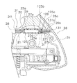
図1に示すように、本発明の一実施形態によるスピニングリール100は、釣り糸を前方に繰り出し可能なリールある。スピニングリール100は、ハンドル1と、ハンドル1を回転自在に支持するリール本体2と、ロータ3と、スプール4とを備えている。ロータ3は、リール本体2の前部に回転自在に支持されている。スプール4は、釣り糸を外周面に巻き取るものであり、ロータ3の前部に前後移動自在に配置されている。なお、ハンドル1はリール本体2の左右いずれにも装着可能である。
As shown in FIG. 1, a spinning
<リール本体の構成>
本発明の一実施形態によるリール本体2は、図2及び図3に示すように、側部が開口する機構装着空間2dを有する筐体部2aと、蓋部材2b(図3)と、筒状部材25と、ボス部26aを有するガード部材26と、ネジ部材27と、第1シール部材28と、第2シール部材29と、を備える。筐体部2aは、前縁部に開口し機構装着空間2dに連通する第1連通部30と、第1連通部30と反対側に配置され、機構装着空間2dと連通し後縁部に開口する第2連通部31と、を有している。
<Structure of reel body>
As shown in FIGS. 2 and 3, a reel
筐体部2aは、たとえば、マグネシウム合金やアルミニウム合金等の軽合金製のものである。筐体部2aには、上部に前後に延びるT字形の釣り竿装着部2eが一体形成されている。筐体部2aの機構装着空間2d内には、図2に示すように、ロータ駆動機構5と、オシレーティング機構6とが設けられている。筐体部2aの前端には、図3、図4、及び図5に示すように、円形のフランジ部2fを構成する概ね半円形の第1フランジ2f1と、フランジ部2fより小径で先端が開口する円筒部2g(図4参照)とが形成されている。第1フランジ2f1には、第1連通部30が開口している。
The
第1連通部30は、ネジ部材27が通過可能な内径を有する丸孔によって構成される。第1連通部30は、筐体部2aの前縁部であるフランジ部2fから第2連通部31に向かって突出する第1突出部2hに形成されている。第1連通部30は、ネジ部材27によりガード部材26を取り付けた後に第1シール部材28により塞がれている。
The
第2連通部31は、筐体部2aの後縁部から第1連通部30に向けて突出する第2突出部2iに形成されている。第2連通部31は、筐体部2aの後縁部に開口する第1孔部31aと、第1孔部31aから筐体部2aの前縁部に向かって形成される第2孔部31bと、第2孔部31bが開口する壁部31cと、を有している。第1孔部31aには、ガード部材26のボス部26aを挿入可能である。第2孔部31bは、第1孔部31aによりも小径である。第2孔部31bには、ネジ部材27の後述するネジ軸部27bが通過可能である。壁部31cは、第2孔部31bが開口し、第2孔部31bに直交する面で構成される。
The 2nd communication part 31 is formed in the
図1及び図3に示すように、蓋部材2bは、機構装着空間2dを塞ぐために筐体部2aに着脱可能に装着される。蓋部材2bは、たとえば、マグネシウム合金やアルミニウム合金等の軽合金製のものである。蓋部材2bは、たとえば、ロータ3で隠れる前側の2箇所で図示しない2本の固定ボルトにより筐体部2aに固定されている。前側の2本の固定ボルトは、筐体部2aの前部に形成された図4に示す2つのネジ穴18にねじ込まれる。また、蓋部材2bは、ロータ3から離反する後側の1箇所で図示しない固定ボルトにより筐体部2aに固定されている。後側の固定ボルトは、筐体部2aの後部に形成されたネジ孔19にねじ込まれる。したがって、前側の2本の固定ボルトはロータ3により隠れる。また、後側の固定ボルトは、ガード部材26によりカバーされる。したがって、蓋部材2bを固定する固定ボルトはリール本体2の外部に露出しない。蓋部材2bの前端には、第1フランジ2f1とともにフランジ部2fを構成する第2フランジ2f2が形成されている。
As shown in FIGS. 1 and 3, the lid member 2b is detachably mounted on the
図3、図4及び図5に示すように、筒状部材25は、例えばポリアミド樹脂又はポリアセタール等の合成樹脂製の部材である。筒状部材25は、筐体部2aの機構装着空間2dに配置されている。筒状部材25は、第1連通部30と第2連通部31との間に配置される。筒状部材25は、第1連通部30に対向して配置されネジ部材27の頭部27aを挿入可能な筒部25aと、底部25bと、シール装着部25cと、を有している。筒部25aは、第1連通部30と実質的に同径の孔を有している。底部25bは、壁部31cに対向して配置される。底部25bは、ネジ部材27のネジ軸部27bが通過可能な貫通孔25dを有している。底部25bは、ネジ部材27の頭部27aを係止可能である。シール装着部25cは、底部25bから壁部31cに向かって筒状に突出している。シール装着部25cの先端部は、壁部31cに接触して配置される。貫通孔25dは、第2連通部31の第2孔部31bと実質的に同径の孔である。
As shown in FIGS. 3, 4, and 5, the tubular member 25 is a member made of synthetic resin such as polyamide resin or polyacetal. The cylindrical member 25 is disposed in the
ガード部材26は、図2、図4及び図5に示すように、筐体部2a及び蓋部材2bを覆うように後方から装着される部材である。ガード部材26は、リール本体2の後部の外形形状を決定している。ガード部材26は、姿合わせのための図示しないパッキンを介して釣り竿装着部2eを含む筐体部2a及び蓋部材2bに装着される。ガード部材26のボス部26aは、中心にネジ部材27がネジ止め固定されるように棒状に形成される。ボス部26aは、前方に突出して形成され、筐体部2aの後縁部から第2連通部31に挿入可能である。具体的には、ボス部26aは、前述したように第2連通部31の第1孔部31aに挿入可能である。ボス部26aの中心には、ネジ部材27がねじ込まれる雌ネジ部26bが形成されている。雌ネジ部26bは、ボス部26aの軸方向の途中の位置まで延びる。ボス部26aは、ガード部材26が固定されたときに、第1孔部31aと第2孔部31bとの段差と隙間を形成可能な長さを有する。
As shown in FIGS. 2, 4, and 5, the
図4に示すように、ネジ部材27は、頭部27aと、頭部27aより小径となるように形成され、外周部に雄ネジ部が形成されたネジ軸部27bと、を有する部材である。この実施形態では、ネジ部材27は、ボス部26aに形成された雌ネジ部26bに螺合するボルト部材である。しかし、ネジ部材は、ボス部26a内に雌ネジ部を形成可能なタッピングビスでもよい。ネジ部材27は、スピニングリール100の組み立て前に筒状部材25に装着される。組立時には、第1連通部30を経由してドライバー等の締付工具の先端を筒状部材25に挿入し、締付工具によってネジ部材27を回してガード部材26のボス部26aにねじ込む。これにより、ガード部材26及び筒状部材25が筐体部2aに固定される。
As shown in FIG. 4, the
第1シール部材28は、筒状部材25と第1連通部30との隙間をシールする。第1シール部材28は、第1連通部30及び筒状部材25の筒部25aのそれぞれの内周面に嵌合する。第1シール部材28は、合成ゴム等の弾性体製の部材である。図4に示すように、第1シール部材28は、第1連通部30に嵌合する第1端部28aの外径が、筒状部材25の筒部25aに嵌合する第2端部28bの外径よりも大きい載頭円錐形状の部材である。第1シール部材28の第1端部28aの外径は、第1連通部30の内径よりも大きく、第2端部28bの外径は、筒状部材25の筒部25aの内径よりも僅かに小さい。これにより、第1シール部材28が先細りの形状になり、第1連通部30を経由して筒状部材25に第1シール部材28を装着しやすくなる。このような構成の第1シール部材28によって、筒状部材25の内部から機構装着空間2d内への液体の浸入を防止できるとともに、第1連通部30から機構装着空間2d内への液体の浸入を防止できる。
The
第2シール部材29は、筒状部材25と第2連通部31との隙間をシールする。第2シール部材は、シール装着部25cに装着されるOリングである。Oリングの線径は、シール装着部25cの突出長さよりも大きい。これにより、シール装着部25cの先端面が壁部31cに当接した状態で第2シール部材29が壁部31cと底部25bとに挟まれて僅かに圧縮する。これにより、第2シール部材29は、底部25bと壁部31cとの隙間をシールする。この結果、第2連通部31に液体が浸入しても筒状部材25から機構装着空間2d内への液体の浸入を防止できる。
The second seal member 29 seals the gap between the tubular member 25 and the second communication portion 31. The second seal member is an O-ring that is attached to the seal attachment portion 25c. The wire diameter of the O-ring is larger than the protruding length of the seal mounting portion 25c. As a result, the second seal member 29 is sandwiched between the
このリール本体2では、ガード部材26を取り付けるためのネジ部材27が第1シール部材28によって覆われている。このため、ネジ部材27が外部に露出しないすっきりとした外観を得ることができる。また、第1連通部30と筒状部材25との隙間が第1シール部材28によってシールされ、第2連通部31と筒状部材との隙間が第2シール部材29によってシールされている。このため、機構装着空間2dへの液体の浸入を抑え、かつネジ部材27を後部に露出させることなくガード部材26を容易に固定できる。また蓋部材2bを筐体部2aに固定するネジ部材もロータ3及びガード部材26により隠れるため、それらの固定ボルトも外部に露出しない。
In the
<スピニングリールのその他の構成>
ロータ駆動機構5は、図3に示すように、ハンドル1が固定された駆動軸10と、駆動軸10に一体又は別体で設けられるフェースギアの形態の駆動ギア11と、駆動ギア11に噛み合うピニオンギア12と、を有している。駆動軸10は、図3に示すように、第1軸受16a及び第2軸受16bによりリール本体2に回転自在に支持されている。第1軸受16aは、筐体部2aに設けられた第1ボス部17aに装着される。第2軸受16bは、蓋部材2bに設けられた第2ボス部17b装着される。駆動ギア11の外周部は、駆動軸10の軸方向において、筐体部2aに配置された筒状部材25と対向して配置される。言い換えれば、筒状部材25は、駆動ギア11と干渉しないように配置される。このため、筒状部材25を設けても駆動ギア11の大径化を阻害しない。このため、この実施形態の駆動ギア11は、従来の駆動ギアよりも直径が大きく歯数が多い。
<Other configuration of spinning reel>
As shown in FIG. 3, the rotor drive mechanism 5 meshes with the
図2に示すように、ピニオンギア12は筒状に形成されており、ピニオンギア12の前部はロータ3の中心部を貫通し、ナット13によりロータ3に固定されている。また、ピニオンギア12は、その軸方向の中間部と後端部とが、それぞれ軸受14a、14bを介してリール本体2に回転自在に支持されている。
As shown in FIG. 2, the
オシレーティング機構6は、図2及び図3に示すように、スプール4の中心部にドラグ機構60を介して連結されたスプール軸15を前後方向に移動させてスプール4を同方向に移動させるための機構である。オシレーティング機構6は、スプール軸15の下方に平行に配置されたトラバースカム軸21と、トラバースカム軸21に沿って前後方向に移動するスライダ22と、トラバースカム軸21の先端に固定された中間ギア23とを有している。スライダ22にはスプール軸15の後端が回転不能に固定されている。中間ギア23はピニオンギア12に噛み合っている。
2 and 3, the
ロータ3は、図2に示すように、リール本体2に対して前後方向の第1軸X回りに回転自在である。ロータ3は、ピニオンギア12に一体回転可能に連結される。ロータ3は、ピニオンギア12に連結される概ね筒状のロータ本体3aと、ロータ本体3aの両側方から延びる第1ロータアーム3b及び第2ロータアーム3cと、を有している。また、ロータ3は、第1ロータアーム3b及び第2ロータアーム3cに揺動可能に連結されるベールアーム40と、を有している。ベールアーム40は、釣り糸をスプール4に巻き取るために設けられる。
As shown in FIG. 2, the rotor 3 is rotatable about the first axis X in the front-rear direction with respect to the
ロータ3は、ローラ型のワンウェイクラッチ51を有する逆転防止機構50により逆転禁止状態と逆転許可状態とに切り換え可能である。この切換操作は、リール本体2の下部に配置された切換レバー52により行える。
The rotor 3 can be switched between a reverse rotation prohibition state and a reverse rotation permission state by a reverse
スプール4は、図2に示すように、ロータ3の第1ロータアーム3bと第2ロータアーム3cとの間に配置されている。スプール4は、スプール軸15の先端にドラグ機構60を介して装着されている。スプール4は、外周に釣り糸が巻かれる糸巻き胴部4aと、糸巻き胴部4aの後方に糸巻き胴部4aと一体形成された筒状のスカート部4bと、糸巻き胴部4aの前端に設けられた大径のフランジ部4cとを有している。
ドラグ機構60は、スプール4の回転を制動するものであり、スプール軸15の先端に螺合するドラグ調整つまみ61と、ドラグ調整つまみ61により押圧されてスプール4を制動する制動部62とを有している。
As shown in FIG. 2, the spool 4 is disposed between the
The
<リール本体の組立手順>
このような構成のスピニングリールでは、リール本体2内にロータ駆動機構5及びオシレーティング機構6を装着するとともに、円筒部2g内に逆転防止機構50を装着する。また、筒状部材25にネジ部材27及び第2シール部材29を装着し、ネジ部材27により筒状部材25を筐体部2aの機構装着空間2d内に仮置きする。この状態で蓋部材2bを筐体部2aにかぶせて、図示しない固定ボルトにより筐体部2aに蓋部材2bを固定する。次に、筐体部2a及び蓋部材2bの後方からガード部材26を装着する。このとき、ガード部材26のボス部26aを第2連通部31の第1孔部31aに挿入する。そして、第1連通部30から、ドライバーなどの締付工具を利用してネジ部材27をボス部26aにネジ込み、ガード部材26及び筒状部材25を筐体部2aに固定する。これにより、リール本体2の組立作業が完了する。
<Reel body assembly procedure>
In the spinning reel having such a configuration, the rotor driving mechanism 5 and the
ここでは、筒状部材25と第1連通部30との隙間及び筒状部材と第2連通部31との隙間が、第1シール部材28及び第2シール部材29によってシールされる。また、筒状部材25の内部に配置された1本のネジ部材27を、後部から第2連通部31に挿入されたボス部26aに螺合させてガード部材26及び筒状部材25を筐体部2aに固定している。このため、機構装着空間2dへの液体の浸入を抑え、かつネジ部材27を後部に露出させることなくガード部材26を容易に筐体部2aに固定できる。
Here, the gap between the tubular member 25 and the
<変形例>
前記実施形態では、筒状部材25のシール装着部25cの先端を第2連通部31の壁部31cに接触させていたが、本発明はこれに限定されない。図6に示すように、変形例では、第2連通部131をボス部126aを挿入可能な第1孔部131aだけで構成する。筒状部材125のシール装着部125cは、第2連通部131の第1孔部131aに嵌合する。変形例では、シール装着部125cの外周面に第2シール部材129を装着するための環状溝125eを形成し、第2シール部材129によってシール装着部125cと第1孔部131aの内周面との隙間をシールしている。また、筒状部材125の底部125bは、第2連通部131の壁部31cに接触している。その他の構成は、前記実施形態と同様なため前記実施形態と同じ符号を付して説明を省略する。
<Modification>
In the said embodiment, although the front-end | tip of the seal mounting part 25c of the cylindrical member 25 was made to contact the
このような構成の変形例では、筒状部材125を機構装着空間2d内に仮置きするときに、筒状部材125が保持されやすくなる。
In the modified example having such a configuration, the
<特徴>
上記実施形態は、下記のように表現可能である。
<Features>
The above embodiment can be expressed as follows.
(A)リール本体2は、釣り竿に装着可能であり、釣り糸を前方に繰り出すスピニングリール100のリール本体2である。リール本体2は、筐体部2aと、蓋部材2bと、ガード部材26と、ネジ部材27と、筒状部材25と、第1シール部材28と、第2シール部材29と、を備える。筐体部2aは、側部が開口する機構装着空間2dと、前縁部に開口し機構装着空間2dと連通する第1連通部30と、第1連通部30と逆側に配置され機構装着空間2dと連通し後縁部に開口する第2連通部31と、を有している。蓋部材2bは、機構装着空間2dを塞ぐために筐体部2aに着脱自在に装着される。ガード部材26は、筐体部2a及び蓋部材2bを覆うように後方から装着される。ガード部材26は、筐体部2aの後縁部から第2連通部31に挿入可能なボス部26aを有している。筒状部材25は、第1連通部30と第2連通部31との間で機構装着空間2d内に少なくとも一部が配置される。第1シール部材28は、筒状部材25と第1連通部30との隙間をシールする。第2シール部材29は、筒状部材25と第2連通部31との隙間をシールする。ネジ部材27は、第1連通部30を通過可能であり、筒状部材25の内部に頭部27aが係止されボス部26aにねじ込まれる。
(A) The
このリール本体2では、頭部27aが筒状部材25に係止された1本のネジ部材27によりガード部材26が筐体部2aに固定される。この筒状部材25は、第1シール部材28及び第2シール部材29により第1連通部30との隙間及び第2連通部31との隙間がシールされる。このため、筒状部材25の内部から機構装着空間2d内に液体が浸入しない。また、1本のネジ部材27によってガード部材26の筐体部2aへの固定と筒状部材25の筐体部2aへの固定とを行える。これにより、機構装着空間2dへの液体の浸入を抑え、かつネジ部材27を後部に露出させることなくガード部材26を容易に固定できるようになる。
In the
(B)リール本体2において、第2連通部31は、後縁部に開口しボス部26aが挿入される第1孔部31aと、第1孔部31aから前縁部に向かって形成されネジ部材27のネジ軸部27bが通過可能であり、第1孔部31aよりも小径の第2孔部31bと、第2孔部31bが開口し第2孔部31bに直交する面を有する壁部31cと、を有している。筒状部材25は、機構装着空間2d内に配置される。筒状部材25は、筒部25aと、底部25bと、を有している。筒部25aは、第1連通部30に対向して配置される。筒部25aは、ネジ部材27の頭部を挿入可能である。底部25bは、壁部31cに対向して配置される。底部25bは、ネジ軸部27bが通過可能な貫通孔25dを有している。底部25bは、頭部27aを係止可能である。第1シール部材28は、第1連通部30と筒部25aとに嵌合する。
(B) In the
この場合には、筒状部材25が機構装着空間2dに配置されるので、蓋部材2bを筐体部2aに固定する前に筒状部材25を機構装着空間2dに配置できる。また、第1シール部材28が第1連通部30と筒部25aとに嵌合するので、第1シール部材28によって筒状部材25を支持できる。
In this case, since the cylindrical member 25 is disposed in the
(C)リール本体2において、第1シール部材28は、第1連通部30に嵌合する第1端部28aが筒部25aに嵌合する第2端部28bよりも大径の載頭円錐形状の弾性体製の部材である。この場合には、第1連通部30を通って筒部25aに装着される第1シール部材28が先細りに形成されるので、第1シール部材28を筒部25aに装着しやすい。
(C) In the
(D)リール本体は、発明2又は3に記載のリール本体において、第2シール部材29は、壁部31cと底部25bとの間に配置される。筒状部材25は、底部25bから壁部31cに向けて円形に突出するシール装着部25cを有している。第2シール部材29は、シール装着部25cの外周面に装着される。この場合には、壁部31cと底部25bとの間に配置される第2シール部材29がシール装着部25cに装着されるので、第2シール部材29を確実に装着できる。
(D) The reel body is the reel body according to the second or third aspect, and the second seal member 29 is disposed between the
(E)リール本体2において、第2シール部材29は、シール装着部25cに装着可能なOリングである。この場合には、市販のOリングによって筒状部材25と第2連通部31との隙間をシールできる。
(E) In the
(F)スピニングリールは、スプール4と、スプール4に釣り糸を巻き取るためのロータ3と、ロータ3を駆動するための駆動ギア11と、を備える。リール本体2において、筒状部材25は、駆動ギア11の軸方向において、駆動ギア11と対向する位置に配置される。この場合には、筒状部材25と駆動ギア11とを軸方向に並べて配置できるので、筒状部材25が駆動ギア11に干渉しない。このため、筒状部材25を設けても駆動ギア11の大径化を図ることができる。
(F) The spinning reel includes a spool 4, a rotor 3 for winding the fishing line around the spool 4, and a
(G)リール本体2において、筐体部2aは、釣り竿に装着可能な釣り竿装着部2eを有する。この場合には、比較的剛性が高い筐体部2aに釣りを行っているときに釣り竿からの力が作用する釣り竿装着部2eが設けられるので、釣り竿装着部2eの強度を確保しやすい。
(G) In the
<他の実施形態>
以上、本発明の一実施形態について説明したが、本発明は上記実施形態に限定されるものではなく、発明の要旨を逸脱しない範囲で種々の変更が可能である。特に、本明細書に書かれた複数の実施形態及び変形例は必要に応じて任意に組合せ可能である。
<Other embodiments>
As mentioned above, although one Embodiment of this invention was described, this invention is not limited to the said embodiment, A various change is possible in the range which does not deviate from the summary of invention. In particular, a plurality of embodiments and modifications described in this specification can be arbitrarily combined as necessary.
(a)前記実施形態では、第2シール部材29としてOリングを開示したが、第2シール部材はOリングに限定されない。例えば、壁部31cと底部25bとの間に配置されるリング状のシートパッキンでもよい。
(A) Although the O-ring is disclosed as the second seal member 29 in the embodiment, the second seal member is not limited to the O-ring. For example, a ring-shaped sheet packing disposed between the
(b)前記実施形態では、筒状部材25を機構装着空間2dにのみ配置したが、本発明はこれに限定されない。図7に示すリール本体202において、筒状部材225は、筐体部202aの第1連通部230と第2連通部231とを貫通して配置される。したがって、筒状部材225は、機構装着空間2dを超えて配置される。第1連通部230は、大径の第3孔部230aと小径の第4孔部230bと、を有している。第2連通部231は筒状部材225が貫通可能に形成される。
(B) In the above embodiment, the cylindrical member 25 is disposed only in the
筒状部材225は、第3孔部230aと第4孔部230bとの段差部分に係止される大径の鍔部225bと、鍔部225bよりも小径の筒部225aと、を有している。筒状部材225は、ネジ部材227の頭部227aを挿入可能な内径を有する第1部分225cと、ガード部材226のボス部226aを挿入可能な内径を有する第2部分225dと、第1部分225cと第2部分225dとの間に配置される小径の第3部分225eと、を内周部に有している。第3部分225eは、ネジ部材227のネジ軸部227bが通過可能な内径を有している。筒部225aの後端部は、筐体部202aよりも後方に突出している。
The cylindrical member 225 includes a large-diameter flange portion 225b that is locked to a step portion between the third hole portion 230a and the fourth hole portion 230b, and a cylindrical portion 225a that is smaller in diameter than the flange portion 225b. Yes. The cylindrical member 225 includes a first portion 225c having an inner diameter into which the head portion 227a of the screw member 227 can be inserted, a second portion 225d having an inner diameter into which the boss portion 226a of the guard member 226 can be inserted, and a first portion 225c. And a small-diameter third portion 225e disposed between the second portion 225d and the second portion 225d. The third portion 225e is threaded
ガード部材226のボス部226aの先端部は、第2部分225dと第3部分225eとの段差よりも後方に配置されている。 The tip of the boss 226a of the guard member 226 is disposed behind the step between the second portion 225d and the third portion 225e.
ネジ部材227は、頭部227aが第1部分225cと第3部分225eとの段差に係止される。ネジ軸部227bは、第3部分225eを貫通してボス部226aに螺合する。ネジ部材227は、例えばタッピングビスである。 As for screw member 227, head 227a is latched by the level difference of the 1st portion 225c and the 3rd portion 225e. The screw shaft portion 227b passes through the third portion 225e and is screwed into the boss portion 226a. The screw member 227 is, for example, a tapping screw.
筒状部材225と第1連通部230との隙間をシールする第1シール部材228は、筒部225aの前部の外周面と第1連通部230との間に配置される。第1シール部材228は、筒部225aの外周面に形成された第1環状溝225fに装着されている。 The first sealing member 228 that seals the gap between the cylindrical member 225 and the first communication portion 230 is disposed between the outer peripheral surface of the front portion of the cylindrical portion 225 a and the first communication portion 230. The first seal member 228 is attached to a first annular groove 225f formed on the outer peripheral surface of the cylindrical portion 225a.
筒状部材225と第2連通部231との隙間をシールする第2シール部材229は、筒部225aの後部の外周面と第2連通部231との間に配置される。第2シール部材229は、筒部225aの後部の外周面に形成された第2環状溝225gに装着されている。第1シール部材228及び第2シール部材229は、Oリングである。筒状部材225の第1部分225cの前側開口部分は、例えば弾性体製のキャップ部材39により塞がれる。 The second seal member 229 that seals the gap between the tubular member 225 and the second communication portion 231 is disposed between the outer peripheral surface of the rear portion of the tubular portion 225a and the second communication portion 231. The second seal member 229 is attached to a second annular groove 225g formed on the outer peripheral surface of the rear portion of the cylindrical portion 225a. The first seal member 228 and the second seal member 229 are O-rings. The front opening portion of the first portion 225c of the cylindrical member 225 is closed by, for example, an elastic cap member 39.
このように形成されたリール本体201では、第1シール部材228及び第2シール部材229を装着した筒状部材225を第1連通部230から挿入し、第2連通部231を貫通して予め筐体部202aに鍔部225bが第3孔部230aと第4孔部230bの段差に接触するまで押し込む。機構装着空間2d内への機構の装着が完了すると、組み立てが完了すると、ガード部材226のボス部226aを筒状部材225と第2部分225dに挿入する。そして、第1部分225cからネジ部材227を挿入し、ガード部材226が筐体部202a及び蓋部材(図示せず)に接触し、かつ鍔部225bが第1連通部230の第3孔部230aと第4孔部230bとの段差に接触するまでねじ込む。これにより、ガード部材226及び筒状部材225が筐体部202aに固定される。
In the reel body 201 formed in this way, the cylindrical member 225 fitted with the first seal member 228 and the second seal member 229 is inserted from the first communication portion 230 and penetrates through the second communication portion 231 in advance. The body part 202a is pushed in until the flange part 225b contacts the step between the third hole part 230a and the fourth hole part 230b. When the mounting of the mechanism in the
このような構成のリール本体202では、筒状部材225の前後の外周部が第1シール部材228及び第2シール部材229によりシールされるので、筒状部材225と第1連通部230及び第2連通部231との隙間から機構装着空間2dへの液体の浸入を防止できる。また、筒状部材225が筐体部202aの前縁部と後縁部とを貫通して設けられるので、筒状部材225の内部に液体が浸入しても、機構装着空間2dへの液体の浸入を防止できる。その他の構成は前記実施形態と同様なため説明を省略する。
In the reel main body 202 having such a configuration, the front and rear outer peripheral portions of the cylindrical member 225 are sealed by the first seal member 228 and the second seal member 229, so the cylindrical member 225, the first communication portion 230, and the second seal member 225 are sealed. It is possible to prevent liquid from entering the
(c)前記実施形態では、筐体部2aに釣り竿装着部2eが一体形成されていたが、蓋部材2bに釣り竿装着部2eが一体形成されてもよい。
(C) In the above-described embodiment, the fishing
2 リール本体
2a 筐体部
2b 蓋部材
2d 機構装着空間
2e 釣り竿装着部
3 ロータ
4 スプール
5 ロータ駆動機構
11 駆動ギア
25 筒状部材
25a 筒部
25b 底部
25c シール装着部
26 ガード部材
26a ボス部
27 ネジ部材
27a 頭部
27b ネジ軸部
28 第1シール部材
28a 第1端部
28b 第2端部
29 第2シール部材
30 第1連通部
31 第2連通部
31a 第1孔部
31b 第2孔部
31c 壁部
100 スピニングリール
125 筒状部材
125c シール装着部
125e 環状溝
129 第2シール部材
131 第2連通部
131a 第1孔部
131c 壁部
202a 筐体部
225 筒状部材
225a 筒部
225b 鍔部
225c 第1部分
225d 第2部分
225e 第3部分
225f 第1環状溝
225g 第2環状溝
226 ガード部材
226a ボス部
227 ネジ部材
227a 頭部
227b ネジ軸部
228 第1シール部材
229 第2シール部材
230 第1連通部
230a 第3孔部
230b 第4孔部
231 第2連通部
2
Priority Applications (7)
| Application Number | Priority Date | Filing Date | Title |
|---|---|---|---|
| JP2012140518A JP5956842B2 (en) | 2012-06-22 | 2012-06-22 | Spinning reel and reel body of spinning reel |
| US13/894,933 US9055735B2 (en) | 2012-06-07 | 2013-05-15 | Spinning reel and spinning-reel reel unit |
| EP13169800.3A EP2671446B1 (en) | 2012-06-07 | 2013-05-29 | Spinning reel and spinning-reel unit |
| TW102118945A TWI631896B (en) | 2012-06-07 | 2013-05-29 | Spinning reel and spinning-reel reel unit |
| CN201310205276.9A CN103478093B (en) | 2012-06-07 | 2013-05-29 | Spinning fishing reel and fishing reel main body thereof |
| KR1020130063651A KR102101238B1 (en) | 2012-06-07 | 2013-06-03 | Spinning reel and spinning-reel reel unit |
| MYPI2013700921A MY165059A (en) | 2012-06-07 | 2013-06-03 | Spinning reel and spinning-reel unit |
Applications Claiming Priority (1)
| Application Number | Priority Date | Filing Date | Title |
|---|---|---|---|
| JP2012140518A JP5956842B2 (en) | 2012-06-22 | 2012-06-22 | Spinning reel and reel body of spinning reel |
Publications (3)
| Publication Number | Publication Date |
|---|---|
| JP2014003923A JP2014003923A (en) | 2014-01-16 |
| JP2014003923A5 true JP2014003923A5 (en) | 2015-04-30 |
| JP5956842B2 JP5956842B2 (en) | 2016-07-27 |
Family
ID=50102304
Family Applications (1)
| Application Number | Title | Priority Date | Filing Date |
|---|---|---|---|
| JP2012140518A Active JP5956842B2 (en) | 2012-06-07 | 2012-06-22 | Spinning reel and reel body of spinning reel |
Country Status (1)
| Country | Link |
|---|---|
| JP (1) | JP5956842B2 (en) |
Families Citing this family (2)
| Publication number | Priority date | Publication date | Assignee | Title |
|---|---|---|---|---|
| JP7013204B2 (en) * | 2017-10-27 | 2022-01-31 | 株式会社シマノ | Spinning reel |
| JP6917284B2 (en) * | 2017-11-27 | 2021-08-11 | グローブライド株式会社 | Mounting structure of the cover member of the spinning reel for fishing |
Family Cites Families (3)
| Publication number | Priority date | Publication date | Assignee | Title |
|---|---|---|---|---|
| JP2000316430A (en) * | 1999-05-10 | 2000-11-21 | Ryobi Ltd | Spinning reel |
| JP4804331B2 (en) * | 2006-12-21 | 2011-11-02 | 株式会社シマノ | Spinning reel body |
| JP4804330B2 (en) * | 2006-12-21 | 2011-11-02 | 株式会社シマノ | Spinning reel body |
-
2012
- 2012-06-22 JP JP2012140518A patent/JP5956842B2/en active Active
Similar Documents
| Publication | Publication Date | Title |
|---|---|---|
| KR102101238B1 (en) | Spinning reel and spinning-reel reel unit | |
| TWI612891B (en) | Spinning wheel reel | |
| JP5254882B2 (en) | Fishing reel | |
| JP4804330B2 (en) | Spinning reel body | |
| JP2015035987A5 (en) | ||
| JP5956842B2 (en) | Spinning reel and reel body of spinning reel | |
| TW201509298A (en) | Spinning reel | |
| JP2006217848A (en) | Handle assembly for spinning reel | |
| JP2014003923A5 (en) | ||
| JP4804331B2 (en) | Spinning reel body | |
| JP5244025B2 (en) | Fishing reel | |
| US8939391B2 (en) | Spinning reel body and spinning reel | |
| KR20110046309A (en) | Spinning Reel Fishing Line Guide | |
| JP2008295375A (en) | Spinning reel for fishing | |
| JP2009106233A (en) | Spinning reel | |
| JP4533425B2 (en) | Cutting blade rotor | |
| JP4709019B2 (en) | Fishing spinning reel | |
| JP4970147B2 (en) | Fishing spinning reel | |
| JP4964709B2 (en) | Fishing reel | |
| JP6586005B2 (en) | Fishing spinning reel | |
| JP2010172252A (en) | Reel body of spinning reel | |
| JP2008295374A (en) | Spinning reel for fishing | |
| JP2007111061A (en) | Spinning reel for fishing | |
| JP2007259811A (en) | Fishing reel | |
| JP4828861B2 (en) | Fishing rod structure |