JP2014002248A - Imaging device, method, and program - Google Patents
Imaging device, method, and program Download PDFInfo
- Publication number
- JP2014002248A JP2014002248A JP2012137058A JP2012137058A JP2014002248A JP 2014002248 A JP2014002248 A JP 2014002248A JP 2012137058 A JP2012137058 A JP 2012137058A JP 2012137058 A JP2012137058 A JP 2012137058A JP 2014002248 A JP2014002248 A JP 2014002248A
- Authority
- JP
- Japan
- Prior art keywords
- light emission
- strobe
- delay time
- exposure
- emission luminance
- Prior art date
- Legal status (The legal status is an assumption and is not a legal conclusion. Google has not performed a legal analysis and makes no representation as to the accuracy of the status listed.)
- Ceased
Links
Images


Classifications
-
- H—ELECTRICITY
- H04—ELECTRIC COMMUNICATION TECHNIQUE
- H04N—PICTORIAL COMMUNICATION, e.g. TELEVISION
- H04N23/00—Cameras or camera modules comprising electronic image sensors; Control thereof
- H04N23/56—Cameras or camera modules comprising electronic image sensors; Control thereof provided with illuminating means
-
- H—ELECTRICITY
- H04—ELECTRIC COMMUNICATION TECHNIQUE
- H04N—PICTORIAL COMMUNICATION, e.g. TELEVISION
- H04N23/00—Cameras or camera modules comprising electronic image sensors; Control thereof
- H04N23/70—Circuitry for compensating brightness variation in the scene
- H04N23/74—Circuitry for compensating brightness variation in the scene by influencing the scene brightness using illuminating means
Abstract
Description
本技術は、撮像装置及び方法、並びにプログラムに関し、特に、高速のシャッタ速度においても適正な調光制御を実現することができる、撮像装置及び方法、並びにプログラムに関する。 The present technology relates to an imaging apparatus, method, and program, and more particularly, to an imaging apparatus, method, and program capable of realizing appropriate dimming control even at a high shutter speed.
従来、撮像装置が、同調速度以上のシャッタ速度でストロボ撮影を行う場合、フラット発光により、被写体を照明して調光する(例えば、特許文献1参照)。フラット発光とは、ストロボ光を連続的に発光することで、定常光と同様の効果を得ることができるものをいう。 2. Description of the Related Art Conventionally, when an imaging apparatus performs strobe shooting at a shutter speed that is equal to or higher than the synchronization speed, the subject is illuminated with light by flat light emission (for example, refer to Patent Document 1). Flat light emission refers to light that can obtain the same effect as steady light by continuously emitting strobe light.
しかしながら、従来の撮像装置が、シャッタ速度を高速にしてストロボ撮影を行う場合、フラット発光のリップルの影響によって、適正な調光制御の実行が困難になるおそれがある。 However, when a conventional imaging apparatus performs strobe shooting at a high shutter speed, it may be difficult to perform proper dimming control due to the influence of flat light emission ripple.
本技術は、このような状況に鑑みてなされたものであり、高速のシャッタ速度においても適正な調光制御を実現できるようにしたものである。 The present technology has been made in view of such a situation, and is capable of realizing appropriate dimming control even at a high shutter speed.
本技術の一側面の撮像装置は、ストロボの発光開始タイミングを示す発光トリガがストロボに対して発行されてから前記ストロボの発光輝度が所定値に到達するまでの遅延時間を取得する発光制御部と、前記遅延時間に基づいて、露光開始タイミングを制御する撮像制御部と、前記露光開始タイミングから撮像された撮像画像に対して明るさを補正する場合に用いられる補正量を、前記遅延時間に基づいて算出する補正量算出部とを備える。 An imaging apparatus according to an aspect of the present technology includes a light emission control unit that acquires a delay time from when a light emission trigger indicating a light emission start timing of a strobe is issued to the strobe until the light emission luminance of the strobe reaches a predetermined value; Based on the delay time, an imaging control unit for controlling the exposure start timing based on the delay time, and a correction amount used when correcting the brightness of the captured image captured from the exposure start timing, And a correction amount calculation unit for calculating.
前記撮像装置と被写体までの距離に基づいて、前記ストロボの発光輝度の前記所定値を算出する発光輝度算出部をさらに備え、前記ストロボによって、前記発光輝度算出部により算出された前記ストロボの発光輝度の前記所定値に対応する前記遅延時間が、発光輝度と遅延時間との関係を示すテーブルから検出されると、前記発光制御部は、前記ストロボにより検出された前記遅延時間を取得することができる。 A light emission luminance calculating unit that calculates the predetermined value of the light emission luminance of the strobe based on the distance between the imaging device and the subject, and the light emission luminance of the strobe calculated by the light emission luminance calculation unit by the strobe When the delay time corresponding to the predetermined value is detected from a table indicating the relationship between the light emission luminance and the delay time, the light emission control unit can acquire the delay time detected by the strobe. .
前記撮像制御部は、前記発光トリガが発行されてから前記遅延時間が経過したタイミングに基づいて、前記露光開始タイミングを設定することができる。 The imaging control unit can set the exposure start timing based on a timing at which the delay time has elapsed after the light emission trigger is issued.
前記撮像制御部は、前記露光開始タイミングから所定の露光時間が経過したタイミングを、露光終了タイミングとして設定し、前記補正量算出部は、前記露光開始タイミングにおける発光輝度と前記露光終了タイミングにおける発光輝度とに基づいて、前記補正量を算出することができる。 The imaging control unit sets a timing at which a predetermined exposure time has elapsed from the exposure start timing as an exposure end timing, and the correction amount calculating unit sets the emission luminance at the exposure start timing and the emission luminance at the exposure end timing. Based on the above, the correction amount can be calculated.
前記所定の露光時間は、前記発光トリガが発行されてストロボの発光輝度が単調増加している期間内、又は、発光輝度が単調増加してピークに到達した後の、単調減少している期間内に設定することができる。 The predetermined exposure time is within a period in which the light emission luminance of the strobe is monotonously increasing after the light emission trigger is issued, or within a period in which the light emission luminance monotonously increases and reaches a peak. Can be set to
前記撮像制御部は、前記ストロボの発光輝度が前記ピークに到達したタイミングに基づいて、前記露光開始タイミングを設定することができる。 The imaging control unit can set the exposure start timing based on the timing at which the light emission luminance of the strobe reaches the peak.
本技術の一側面の撮像方法及びプログラムは、上述した本技術の一側面の撮像装置に対応する方法及びプログラムである。 An imaging method and program according to one aspect of the present technology are a method and program corresponding to the imaging device according to one aspect of the present technology described above.
本技術の一側面の撮像装置及び方法並びにプログラムにおいては、ストロボの発光開始タイミングを示す発光トリガがストロボに対して発行されてから前記ストロボの発光輝度が所定値に到達するまでの遅延時間が取得され、前記遅延時間に基づいて、露光開始タイミングが制御され、前記露光開始タイミングから撮像された撮像画像に対して明るさを補正する場合に用いられる補正量が、前記遅延時間に基づいて算出される。 In the imaging apparatus, method, and program according to one aspect of the present technology, a delay time from when a light emission trigger indicating the light emission start timing of the strobe is issued to the strobe until the light emission luminance of the strobe reaches a predetermined value is acquired. An exposure start timing is controlled based on the delay time, and a correction amount used when correcting the brightness of a captured image captured from the exposure start timing is calculated based on the delay time. The
以上のごとく、本技術によれば、高速のシャッタ速度においても適正な調光制御を実現することができる。 As described above, according to the present technology, appropriate dimming control can be realized even at a high shutter speed.
[フラット発光のリップル]
はじめに、本技術の理解を容易なものとすべく、所定の速度以上のシャッタ速度で撮像する場合におけるフラット発光のリップルの影響について説明する。
[Ripple of flat light emission]
First, in order to facilitate understanding of the present technology, the influence of ripples of flat light emission when imaging at a shutter speed higher than a predetermined speed will be described.
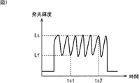
図1は、フラット発光における発光輝度の時間推移を示す図である。図1において、横軸は、時間軸を示し、縦軸は、発光輝度を示している。図1に示されるように、発光輝度は、発光期間において周期的に変化する。 FIG. 1 is a diagram showing a time transition of light emission luminance in flat light emission. In FIG. 1, the horizontal axis indicates the time axis, and the vertical axis indicates the light emission luminance. As shown in FIG. 1, the light emission luminance periodically changes during the light emission period.
フラット発光における発光輝度の時間推移を示す波形において、リップル周波数は30kHz乃至50kHzであり、1Ev程度の波高値のばらつきがある。したがって、所定の速度以上、例えば10万分の1秒のシャッタ速度で撮像される場合、露光のタイミングによっては、最大で1Ev程度の露光のばらつきが発生する。 In the waveform showing the time transition of the light emission luminance in flat light emission, the ripple frequency is 30 kHz to 50 kHz, and there is a variation in peak value of about 1 Ev. Therefore, when imaging is performed at a predetermined speed or higher, for example, at a shutter speed of 1 / 100,000 seconds, exposure variation of about 1 Ev at maximum occurs depending on the exposure timing.
具体的には、フラット発光のリップルとは無関係に露光が行われることになるため、時刻ts1のタイミングで露光が行われる場合もあるし、時刻ts2のタイミングで露光が行われる場合もある。この場合、図1に示されるように、時刻ts1のタイミングでは発光輝度Lfのストロボ光によって露光が行われるのに対して、時刻ts2のタイミングでは、時刻ts1のときよりも明るい発光輝度Lsのストロボ光によって露光が行われることになる。 Specifically, since the exposure is performed regardless of the ripple of the flat light emission, the exposure may be performed at the timing of time ts1, or the exposure may be performed at the timing of time ts2. In this case, as shown in FIG. 1, exposure is performed with strobe light having a light emission luminance Lf at time ts1, whereas a strobe with light emission luminance Ls that is brighter than at time ts1 at time ts2. Exposure is performed by light.
このように、所定の速度以上のシャッタ速度で撮像される場合、フラット発光のリップルの影響により、適正な調光制御が困難になるおそれがある。 As described above, when an image is captured at a shutter speed that is equal to or higher than a predetermined speed, it is difficult to perform proper dimming control due to the influence of a ripple of flat light emission.
そこで、本発明者等は、所定の速度以上のシャッタ速度においても適正な調光制御を実現すべく、以下に説明するような本技術の手法を開発した。 Accordingly, the present inventors have developed a technique of the present technology as described below in order to realize appropriate dimming control even at a shutter speed equal to or higher than a predetermined speed.
[本技術の手法の概略]
本技術の手法の理解を容易なものとすべく、その概略について説明する。
[Outline of the technique of this technology]
In order to facilitate understanding of the technique of the present technology, an outline thereof will be described.
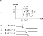
図2は、本技術の手法について説明する図である。 FIG. 2 is a diagram illustrating a technique of the present technology.
図2Aは、本技術が適用される撮像装置による記録用の撮像時における、外付ストロボによる発光(以下、本発光と称する)の輝度のタイミングチャートである。図2Aにおいて、横軸は、時間軸を示し、縦軸は、発光輝度を示している。 FIG. 2A is a timing chart of luminance of light emitted by an external strobe (hereinafter referred to as “main light emission”) at the time of image pickup for recording by an image pickup apparatus to which the present technology is applied. In FIG. 2A, the horizontal axis indicates the time axis, and the vertical axis indicates the light emission luminance.
図2Bは、外付ストロボ21(後述する図3参照)に対する発光トリガの発行タイミングを示すタイミングチャートである。外付ストロボ21は、発光開始タイミングを示す発光トリガが撮像装置1(後述する図3参照)の本体部から発行されると、本発光する。なお、以下では、本技術が適用される撮像装置1から外付ストロボ21を除く部分を、撮像装置1の本体部101(後述する図3参照)と称する。
FIG. 2B is a timing chart showing the emission trigger issuance timing for the external strobe 21 (see FIG. 3 described later). The
図2Cは、撮像装置1の本体部101の内部での露光開始トリガの発行タイミングを示すタイミングチャートである。撮像装置1の本体部101が、露光開始トリガを内部の撮像素子44(後述する図3参照)に発行すると、撮像素子44は露光を開始する。
FIG. 2C is a timing chart showing the issuance timing of the exposure start trigger inside the
図2Dは、撮像装置1の本体部101の内部での露光終了トリガの発行タイミングを示すタイミングチャートである。撮像装置1の本体部101が、露光終了トリガを内部の撮像素子44に発行すると、撮像素子44は露光を終了する。
FIG. 2D is a timing chart showing the issuance timing of the exposure end trigger inside the
撮像装置1の本体部101は、外付ストロボ21に対して、本発光の前に所定の発光量で予備的に発光(以下、プリ発光と称する)するように指示をする。
The
外付ストロボ21は、プリ発光の指示が発行されると、所定の発光輝度でプリ発光する。すると、撮像装置1の本体部101は、プリ発光の反射光に基づいて、被写体までの距離を算出する。撮像装置1の本体部101は、被写体までの距離に基づいて、本発光に必要な発光輝度L1を算出する。なお、発光輝度L1の算出の具体的な手法については後述する。撮像装置1の本体部101は、算出された発光輝度L1を外付ストロボ21に対して通知する。
When an instruction for pre-emission is issued, the
ここで、外付ストロボ21は、発光遅延時間と発光輝度とが予め対応付けられたテーブルを有している。そこで、外付ストロボ21は、通知された発光輝度L1に対応する発光遅延時間Tdを当該テーブルから検出する。発光遅延時間Tdは、発光トリガが発行されてから外付ストロボ21の発光輝度が所定値に到達するまでに要する時間であり、図2の場合、発光トリガが発行されてから外付ストロボ21が発光輝度L1で発光するまでに要する時間である。外付ストロボ21は、検出された発光遅延時間Tdを撮像装置1の本体部101に通知する。
Here, the
撮像装置1の本体部101は、通知された発光遅延時間Tdに基づいて、発光トリガと露光開始タイミングを示す露光開始トリガとをそれぞれ発行する。図2の場合、発光トリガの発行時刻を時刻teとすると、露光開始トリガの発行時刻は、時刻teから発光遅延時間Td後の時刻tsとされる。
The
外付ストロボ21は、発光トリガが発行された時刻teに本発光する。この場合、外付ストロボ21の本発光による発光輝度の波形は、例えば図2に示されるように、時刻teで直ちにピークにならずに、徐々に単調増加していき、所定の遅れを持ってピークの発光輝度L1に到達すると、今度は徐々に単調減少していくような曲線Cになる。
The
また、撮像装置1の本体部101が、時刻tsに露光開始トリガを発行すると、内部の撮像素子44は露光を開始する。図2の場合、発光輝度がピークの発光輝度L1となる時刻tsから露光が開始される。
Further, when the
その後、撮像装置1の本体部101が、露光開始トリガを発行した時刻tsから露光時間Tss後の時刻tfに露光終了トリガを発行すると、内部の撮像素子44は露光を終了する。なお、露光時間Tssは、予め所定の値に設定されている。このとき、露光終了トリガは、外付ストロボ21にも通知される。
Thereafter, when the
外付ストロボ21は、露光終了トリガを受信した時刻、即ち露光が終了した時刻(この時刻は露光終了トリガが発行された時刻tfに略等しい)の発光輝度L2を測定する。外付ストロボ21は、測定した発光輝度L2を撮像装置1の本体部101に通知する。
The
撮像装置1の本体部101は、先に算出した発光輝度L1と、外付ストロボ21から通知された発光輝度L2とに基づいて、本発光時の発光量の不足分を算出する。
The
具体的には、本来、外付ストロボ21の本発光により、撮像装置1の本体部101(即ち、撮像素子44の受光)に必要となる発光量は、露光時間Tss(即ち、露光開始トリガが発行されてから露光終了トリガが発行されるまでの時間)の期間中、一定の発光輝度L1で外付ストロボ21が発光を継続した場合の発光量GN(ガイドナンバー)である。しかしながら、外付ストロボ21の本発光による実際の発光輝度は、一定とはならず、発光トリガが発行されると先ず単調増加し、所定の遅れを持ってピークの発光輝度L1に到達すると、今度は単調減少する。このため、露光時間が、発光輝度の単調増加又は単調減少の期間を含むと、当該期間の発光輝度では、本来必要な発光量より不足した発光量でストロボが発光していることになる。
Specifically, the amount of light emission originally required for the
そこで、撮像装置1の本体部101は、本発光のうち、発光輝度の単調増加又は単調減少の期間における、発光量の不足分を算出する。即ち、露光時間が、単調増加している期間内、又は、単調減少している期間内に設定される。
Therefore, the
従来のフラット発光では、レリーズ要求と、ストロボのリップルとが無関係であったため、レリーズ要求のタイミング毎に、発光輝度の単調増加又は単調減少の期間と露光時間との関係が場合によって変化してしまい、発光量の不足分を算出することは非常に困難である。 In conventional flat light emission, the release request and strobe ripple are irrelevant, so the relationship between the period of monotonic increase or decrease in emission brightness and the exposure time varies depending on the release request timing. It is very difficult to calculate the shortage of light emission amount.
これに対して、本技術の手法では、レリーズ要求に応じて発光トリガと露光開始トリガとが適切に一定のタイミングに調整されるので、レリーズ要求のタイミングによらず、発光輝度の単調増加又は単調減少の期間と露光時間との関係を一定に保つことができる。このため、本技術の撮像装置1の本体部101は、発光輝度の単調増加又は単調減少の期間における、発光量の不足分を算出することが可能になる。
On the other hand, according to the technique of the present technology, the light emission trigger and the exposure start trigger are appropriately adjusted at a constant timing according to the release request, so that the light emission luminance increases monotonously or monotonically regardless of the release request timing. The relationship between the decrease period and the exposure time can be kept constant. For this reason, the
さらに、発光輝度の単調減少の期間だけに発光量の不足分が現れれば、発光輝度の単調増加と単調減少との両期間に発光量の不足分が現れる場合、即ちピークの発光輝度L1を挟むように露光時間が設定される場合と比較して、発光量の不足分の算出が非常に容易になる。そこで、露光時間がピークの発光輝度L1を挟まないように、露光開始トリガの発行タイミングが調整されると好適である。 Furthermore, if a shortage of the light emission amount appears only during the monotonic decrease period of the light emission luminance, a shortage of the light emission amount appears during both the monotonous increase and the monotonic decrease of the light emission luminance, that is, sandwiching the peak light emission luminance L1. Thus, in comparison with the case where the exposure time is set, it is very easy to calculate the shortage of the light emission amount. Therefore, it is preferable that the exposure start trigger issuance timing is adjusted so that the light emission luminance L1 having the peak exposure time is not sandwiched.
具体的には、図2に示すように、本発光のストロボがピークの発光輝度L1に到達したタイミングで、露光開始トリガが発行されると好適である。この場合には、輝度の単調減少の期間だけに発光量の不足分が現れることになる。図2Aの場合には、左下がりのハッチングで示される領域(期間Tssの発光曲線Cより上の領域)r2の面積が、この発光量の不足分に相当する。即ち、図2Aの場合には、本発光時の実際の発光量は、右下がりのハッチングで示される領域(期間Tssの発光曲線Cより下の領域)r1の面積が相当する。つまり、発光量GNは、図2Aの場合には、領域r1と領域r2とから構成される長方形の面積分の発光量に相当する。しかしながら、実際には、領域r2の面積分だけ発光量が不足することになる。 Specifically, as shown in FIG. 2, it is preferable that the exposure start trigger is issued at the timing when the main light emission strobe reaches the peak light emission luminance L1. In this case, the shortage of light emission appears only during the period of monotonous decrease in luminance. In the case of FIG. 2A, the area of the region r2 (region above the light emission curve C in the period Tss) indicated by hatching that falls to the left corresponds to the shortage of the light emission amount. That is, in the case of FIG. 2A, the actual light emission amount during the main light emission corresponds to the area of the region r1 (region below the light emission curve C in the period Tss) indicated by the right-down hatching. That is, in the case of FIG. 2A, the light emission amount GN corresponds to the light emission amount for the rectangular area composed of the region r1 and the region r2. However, in actuality, the light emission amount is insufficient by the area of the region r2.
このため、本発光時に撮像された撮像画像(即ち、露光開始トリガが発行されてから撮像された撮像画像)は、この本発光時の発光量の不足分だけ暗い画像となっているため、所定のゲインを用いて明るさの補正をする必要がある。そこで、撮像装置1の本体部101は、領域r2の面積分に相当する、本発光時の発光量の不足分を算出し、当該不足分に基づいてゲインを算出する。そして、撮像装置1の本体部101は、算出されたゲインを用いて、本発光時に撮像した撮像画像の画像データに対して明るさを補正する画像処理を施す。
For this reason, the captured image captured during the main light emission (that is, the captured image captured after the exposure start trigger is issued) is a dark image corresponding to the shortage of the light emission amount during the main light emission. It is necessary to correct the brightness by using the gain. Therefore, the
このように、本技術の手法においては、撮像装置1の本体部101は、外付ストロボ21から本発光の前に通知された発光遅延時間Tdに基づいて、発光トリガと露光開始トリガを発行するタイミングを調整する。即ち、レリーズ要求のタイミングにかかわらず、ストロボの発光段階のうち適切な段階で露光が開始されるように、撮像装置1の本体部101は、発光トリガと露光開始トリガを発行するタイミングを調整する。これにより、高速のシャッタ速度においても適正な調光制御を実現することができる。
As described above, in the technique of the present technology, the
[撮像装置の機能的構成例]
図3は、本技術が適用される撮像装置1の機能的構成例を示すブロック図である。
[Functional configuration example of imaging device]
FIG. 3 is a block diagram illustrating a functional configuration example of the
撮像部11は、ズームレンズ41、絞り42、フォーカスレンズ43、及び撮像素子44から構成される。ズームレンズ41は、焦点距離を一定の範囲で自在に変化させる光学レンズである。絞り42は、ズームレンズ41を通過して入射してくる光の一部を遮光して、フォーカスレンズ43を介して撮像素子44へ入射する光の光量を調節する。フォーカスレンズ43は、撮像素子44の受光面に被写体像を結像させるため光学レンズである。
The imaging unit 11 includes a
撮像素子44は、例えば、CCD(Charge Coupled Devices)センサやCMOS(Complementary Metal Oxide Semiconductor)センサ等で構成される。撮像素子44は、CPU(Central Processing Unit)16から供給されるタイミング信号に従って動作することにより、ズームレンズ41、絞り42、及びフォーカスレンズ43を介して入射する被写体からの光を受光して光電変換を行う。そして、撮像素子44は、受光量に応じた電気信号としてのアナログの画像信号を、A/D(Analog/Digital)変換部12に供給する。
The
A/D変換部12は、撮像素子44からのアナログ信号の画像信号をA/D変換し、その結果得られるデジタル信号を、画像データとして、CPU16に供給する。
The A / D converter 12 A / D converts the analog image signal from the
画像データ処理部13は、画像データをCPU16から取得して、各種画像処理を適宜施した上で、表示部15や記録デバイス14に供給する。例えば、画像データ処理部13は、CPU16から記録の指示を受けた場合、CPU16から取得した画像データに対してJPEG(Joint Photographic Experts Group)方式等を用いた圧縮符号化処理を施し、その結果得られる圧縮符号化データを、記録デバイス14に記録させる。
The image
また、画像データ処理部13は、記録デバイス14に記録された圧縮符号化データを読み出して伸張復号処理を施し、その結果得られる撮像画像等のデータを表示部15に供給する。このようにして、表示部15に撮像画像等のデータが供給された場合、当該撮像画像等が表示部15に表示される。
In addition, the image
記録デバイス14は、例えば、DVD(Digital Versatile Disc)等のディスクや、メモリカード等の半導体メモリその他のリムーバブルなリムーバブル記録媒体であり、撮像装置1に対して、容易に着脱可能になっている。記録デバイス14には、例えば撮影画像のデータ等が記録される。
The
CPU16は、プログラムROM(Read Only Memory)19に記録されているプログラムを実行することにより、撮像装置1を構成する各部を制御し、また、操作部17からの信号に応じて、各種の処理を行う。
The
本実施形態では、CPU16は、所定のプログラムを実行することにより、操作検出部61、発光制御部62、撮像制御部63、画像データ取得部64、距離算出部65、輝度算出部66、及びゲイン算出部67として機能する。
In the present embodiment, the
操作検出部61は、操作部17に対するユーザの操作を検出する。操作検出部61は、操作部17に含まれるレリーズボタンがユーザにより押下されたことを、レリーズ要求として検出して、発光制御部62と撮像制御部63に通知する。
The
発光制御部62は、操作検出部61からレリーズ要求が通知されると、外付ストロボ21に対してプリ発光の指示を発行する。すると、外付ストロボ21は、所定の発光輝度でプリ発光する。
When a release request is notified from the
撮像制御部63は、操作検出部61からレリーズ要求が通知されると、撮像部11の撮像動作の制御を開始する。具体的には例えば、撮像制御部63は、ズームレンズ41の焦点距離、絞り42の絞り値、フォーカスレンズ43の駆動を伴うオートフォーカス処理を制御する。このような撮像制御部63の制御の下、撮像部11からA/D変換部12に供給され、A/D変換された画像信号が、画像データとして画像データ取得部64に供給される。また、撮像制御部63は、撮像時の絞り値を輝度算出部66に供給する。
When receiving a release request from the
画像データ取得部64は、画像データをA/D変換部12から取得すると、画像データ処理部13に供給する。また、画像データ取得部64は、プリ発光時に撮像された画像データをA/D変換部12から取得すると、距離算出部65にも供給する。
When the image
距離算出部65は、プリ発光時において、画像データ取得部64から供給された画像データに基づいて、撮像装置1から被写体までの距離を算出し、輝度算出部66に供給する。
The
輝度算出部66は、撮像制御部63から供給された絞り値と、距離算出部65から供給された被写体までの距離とに基づいて、本発光に必要な発光輝度L1を算出する。
The
具体的には、輝度算出部66は、被写体までの距離と絞り値との積(距離×しぼり値)を、本発光により必要となる発光量GNとして算出する。ここで、上述したように、発光量GNは、図2Aの長方形の面積に相当し、露光時間Tssは予め決められている。したがって、輝度算出部66は、求めた発光量GNを露光時間Tssで除算することで、発光輝度L1を算出することができる。輝度算出部66は、算出された発光輝度L1を発光制御部62に供給する。
Specifically, the
発光制御部62は、輝度算出部66から供給された発光輝度L1を、CPU16に接続されている外付ストロボ21に通知する。すると、外付ストロボ21から、発光輝度L1に対応する発光遅延時間Tdが、発光制御部62に通知される。
The light
発光制御部62は、外付ストロボ21から通知された発光遅延時間Tdに基づいて、発光トリガを発行する。発光制御部62により発光トリガが発行されると、外付ストロボ21は発光輝度L1で本発光する。
The light
また、撮像制御部63は、外付ストロボ21から通知された発光遅延時間Tdに基づいて、例えば外付ストロボ21による本発光において発光輝度がピークの発光輝度L1に到達したタイミングで、露光開始トリガを発行する。撮像制御部63により露光開始トリガが発行されると、撮像素子44は露光を開始する。その後、露光開始トリガが発行された時刻から予め設定された露光時間Tssが経過すると、撮像制御部63は、露光終了トリガを発行する。撮像制御部63により露光終了トリガが発行されると、撮像素子44は露光を終了する。
Further, the
撮像制御部63は、発光制御部62を介して外付ストロボ21に露光終了トリガを通知する。すると、外付ストロボ21から、露光が終了した時刻の発光輝度L2が、発光制御部62に通知される。
The
ゲイン算出部67は、輝度算出部66により算出された発光輝度L1と発光制御部62に通知された発光輝度L2とに基づいて、上述したように、本発光時の発光量の不足分を算出し、当該不足分に基づいてゲインを算出する。具体的には、ここでは図2に示すように、外付ストロボ21による本発光においてピークの発光輝度L1に到達したタイミングで、露光開始トリガが発行されている。そこで、発光量GNから領域r1の面積分の発光量が減算された結果得られる領域r2の面積が、本発光時の発光量の不足分として算出され、当該不足分に基づいてゲインが算出される。ゲイン算出部67は、算出されたゲインを画像データ処理部13に供給する。
Based on the light emission luminance L1 calculated by the
画像データ処理部13は、ゲイン算出部67から供給されたゲインを用いて、本発光時に撮像部11により撮像されて画像データ取得部64を介して供給された画像データに対して、明るさを補正する画像処理を施す。
The image
このようなCPU16には、上述したA/D変換部12、及び画像データ処理部13の他さらに、操作部17、EEPROM(Electrically Erasable Programmable ROM)18、プログラムROM19、RAM(Random Access Memory)20、及び外付ストロボ21が接続されている。
In addition to the A /
操作部17は、ユーザによって操作され、その操作に対応した信号を、CPU16に供給する。操作部17には、例えば、図示せぬ電源ボタン、レリーズボタン、ズームボタン、操作ボタン等が含まれる。
The operation unit 17 is operated by the user and supplies a signal corresponding to the operation to the
EEPROM18は、CPU16の制御にしたがい、各種データを記憶し、撮像装置1の電源がオフにされた後にも保持しておく。換言すると、撮像装置1の電源がオフにされたときにも保持しておく必要があるデータ、例えば撮像装置1に設定された情報等が、EEPROM18に記憶される。
The
プログラムROM19は、CPU16が実行するプログラムを記憶し、さらには、CPU16がプログラムを実行する上で必要なデータを記憶している。RAM20は、CPU16が各種の処理を行う上で必要なプログラムやデータを一時記憶する。
The
外付ストロボ21は、発光部80、時間検出部81、テーブル記憶部82、及び輝度測定部83から構成される。
The
発光部80は、CPU16からプリ発光の指示が発行されると、所定の発光輝度でプリ発光する。また、発光部80は、CPU16から発光トリガが発行されると、プリ発光後に通知された発光輝度で本発光する。
When a pre-flash instruction is issued from the
時間検出部81は、CPU16から通知された発光輝度L1に対応する発光遅延時間Tdを、テーブル記憶部82に記憶されているテーブルから検出する。時間検出部81は、検出された発光遅延時間TdをCPU16に通知する。
The
テーブル記憶部82は、発光遅延時間と発光輝度とが予め対応付けられたテーブルを記憶する。
The
輝度測定部83は、CPU16により露光終了トリガが発行された時刻の発光輝度L2を測定する。輝度測定部83は、測定された発光輝度L2をCPU16に通知する。
The
なお、撮像装置1から外付ストロボ21を除いた撮像装置1の部分が、本体部101に該当する。
Note that the part of the
[撮像装置の処理]
次に、このような構成の撮像装置1の処理の流れについて、図4乃至図6を参照して説明する。
[Processing of imaging device]
Next, a processing flow of the
図4は、撮像装置1の本体部101による調光制御処理の流れの一例を説明するフローチャートである。図5は、外付ストロボ21による発光処理の流れの一例を説明するフローチャートである。また、図6は、撮像装置1の本体部101と外付ストロボ21の間の処理の関係について説明する図である。
FIG. 4 is a flowchart for explaining an example of the flow of dimming control processing by the
ステップS1において、本体部101の操作検出部61は、操作部17に対するレリーズ要求を検出する。検出されたレリーズ要求は、発光制御部62と撮像制御部63に通知される。
In step S <b> 1, the
ステップS2において、発光制御部62は、外付ストロボ21に対してプリ発光の指示を発行する。
In step S <b> 2, the light
すると、ステップS31において、外付ストロボ21の発光部80は、CPU16からプリ発光の指示を受信する。
Then, in step S31, the
ステップS32において、発光部80は、所定の発光輝度でプリ発光する。
In step S32, the
すると、ステップS3において、本体部101の撮像制御部63は、撮像部11の撮像を制御する。プリ発光時に撮像された画像信号は、A/D変換部12においてA/D変換されて画像データとされる。また、撮像時の絞り値が輝度算出部66に供給される。
Then, in step S <b> 3, the
ステップS4において、画像データ取得部64は、プリ発光時に撮像された画像データをA/D変換部12から取得する。
In step S <b> 4, the image
ステップS5において、距離算出部65は、画像データ取得部64により取得されたプリ発光時の画像データに基づいて、撮像装置1から被写体までの距離を算出する。
In step S <b> 5, the
ステップS6において、輝度算出部66は、発光輝度L1を算出する。即ち、輝度算出部66は、撮像制御部63から供給された絞り値と、距離算出部65により算出された被写体までの距離とに基づいて、本発光に必要な発光輝度L1を算出する。具体的には、被写体までの距離と絞り値との積で表わされる発光量GNが、露光時間Tssで除算されることにより発光輝度L1が算出される。
In step S6, the
ステップS7において、発光制御部62は、輝度算出部66により算出された発光輝度L1を、外付ストロボ21に通知する。
In step S <b> 7, the light
すると、ステップS33において、外付ストロボ21は、CPU16から通知された発光輝度L1を受信する。
Then, in step S33, the
ステップS34において、時間検出部81は、発光輝度L1に対応する発光遅延時間Tdを、テーブル記憶部82に記憶されているテーブルから検出する。
In step S <b> 34, the
ステップS35において、時間検出部81は、検出された発光遅延時間Tdを、CPU16に通知する。
In step S35, the
すると、ステップS8において、本体部101の発光制御部62は、外付ストロボ21から通知された発光遅延時間Tdを受信する。
Then, in step S8, the light
ステップS9において、発光遅延時間Tdに基づいて、発光制御部62は発光トリガを発行し、撮像制御部63は露光開始トリガを発行する。
In step S9, based on the light emission delay time Td, the light
ステップS10において、本体部101の撮像素子44は、露光を開始する。即ち、発光輝度がピークの発光輝度L1となる時刻から露光が開始される。なお、ステップS9において発行された発光トリガは、外付ストロボ21にも通知される。
In step S10, the
すると、ステップS36において、発光部80は、ステップS9においてCPU16により発行された発光トリガを受信する。
Then, in step S36, the
ステップS37において、発光部80は、発光輝度L1で本発光する。
In step S37, the
ステップS11において、本体部101の撮像制御部63は、露光終了トリガを発行する。即ち、撮像制御部63は、露光開始トリガが発行された時刻から予め設定された露光時間Tssが経過すると、露光終了トリガを発行する。
In step S11, the
ステップS12において、撮像素子44は、露光を終了する。なお、ステップS11において発行された露光終了トリガは、外付ストロボ21にも通知される。
In step S12, the
すると、ステップS38において、外付ストロボ21は、CPU16により発行された露光終了トリガを受信する。
Then, in step S38, the
ステップS39において、輝度測定部83は、CPU16により露光終了トリガが発行された時刻の発光輝度L2を測定する。
In step S39, the
ステップS40において、輝度測定部83は、測定された発光輝度L2を、CPU16に通知する。これにより、外付ストロボ21の発光処理は終了する。
In step S40, the
すると、ステップS13において、本体部101の発光制御部62は、外付ストロボ21から通知された発光輝度L2を受信する。
Then, in step S13, the light
ステップS14において、ゲイン算出部67は、ゲインを算出する。即ち、ゲイン算出部67は、輝度算出部66により算出された発光輝度L1と発光制御部62に通知された発光輝度L2とに基づいて、本発光時の発光量の不足分を算出し、当該不足分に基づいてゲインを算出する。
In step S14, the
ステップS15において、画像データ処理部13は、ゲイン算出部67により算出されたゲインを用いて、本発光時に撮像された画像データに対して、明るさを補正する画像処理を施す。これにより、本体部101の調光制御処理は終了する。
In step S <b> 15, the image
このように、本技術の手法においては、撮像装置1の本体部101は、外付ストロボ21から本発光の前に通知された発光遅延時間Tdに基づいて、ストロボの発光段階のうち適切な段階で露光が開始されるように、発光トリガと露光開始トリガを発行するタイミングを調整する。これにより、高速のシャッタ速度においても適正な調光制御を実現することができる。
As described above, according to the technique of the present technology, the
上述の例では、外付ストロボ21により発光処理が実行された。しかしながら、ストロボは外付に限定されず、本体部101に内蔵されてもよい。この場合、CPU16に時間検出部81及び輝度測定部83が設けられる。また、テーブル記憶部82は、EEPROM18に設けられる。
In the above example, the light emission processing is executed by the
[本技術のプログラムへの適用]
上述した一連の処理は、ハードウエアにより実行させることもできるし、ソフトウエアにより実行させることができる。
[Application of this technology to programs]
The series of processes described above can be executed by hardware or can be executed by software.
一連の処理をソフトウエアにより実行させる場合には、そのソフトウエアを構成するプログラムが、専用のハードウエアに組み込まれているコンピュータ、または、各種のプログラムをインストールすることで、各種の機能を実行することが可能な、例えば汎用のパーソナルコンピュータなどに、ネットワークや記録媒体からインストールされる。 When a series of processing is executed by software, a program constituting the software executes various functions by installing a computer incorporated in dedicated hardware or various programs. For example, a general-purpose personal computer is installed from a network or a recording medium.
例えば、CPU16に実行させるプログラムは、あらかじめプログラムROM19にインストール(記憶)させておくこともできる。その他、プログラムが記憶された記録デバイス14を、パッケージメディアとして撮像装置1のユーザに提供することもできる。この場合には当該プログラムは、CPU16の制御にしたがって、パッケージメディアとして提供された記録デバイス14から読み出されて、EEPROM18にインストールされる。
For example, a program to be executed by the
また、CPU16に実行させるプログラムは、図示はしないが、インターネット等のネットワークを介在する通信機能が撮像装置1に備えられている場合、ダウンロードサイトから、撮像装置1に直接ダウンロードされ、あるいは、図示せぬコンピュータでダウンロードされて撮像装置1に供給されることによって、EEPROM18にインストールされる。また、プログラムは、ローカルエリアネットワーク、インターネット、デジタル衛星放送といった、有線または無線の伝送媒体を介して提供することができる。
Further, although not shown, the program to be executed by the
なお、コンピュータが実行するプログラムは、本明細書で説明する順序に沿って時系列に処理が行われるプログラムであっても良いし、並列に、あるいは呼び出しが行われたとき等の必要なタイミングで処理が行われるプログラムであっても良い。 The program executed by the computer may be a program that is processed in time series in the order described in this specification, or in parallel or at a necessary timing such as when a call is made. It may be a program for processing.
本技術の実施の形態は、上述した実施の形態に限定されるものではなく、本技術の要旨を逸脱しない範囲において種々の変更が可能である。 Embodiments of the present technology are not limited to the above-described embodiments, and various modifications can be made without departing from the gist of the present technology.
例えば、本技術は、1つの機能をネットワークを介して複数の装置で分担、共同して処理するクラウドコンピューティングの構成をとることができる。 For example, the present technology can take a configuration of cloud computing in which one function is shared by a plurality of devices via a network and is jointly processed.
また、上述のフローチャートで説明した各ステップは、1つの装置で実行する他、複数の装置で分担して実行することができる。 In addition, each step described in the above flowchart can be executed by being shared by a plurality of apparatuses in addition to being executed by one apparatus.
さらに、1つのステップに複数の処理が含まれる場合には、その1つのステップに含まれる複数の処理は、1つの装置で実行する他、複数の装置で分担して実行することができる。 Further, when a plurality of processes are included in one step, the plurality of processes included in the one step can be executed by being shared by a plurality of apparatuses in addition to being executed by one apparatus.
なお、本技術は、以下のような構成もとることができる。
(1)
ストロボの発光開始タイミングを示す発光トリガがストロボに対して発行されてから前記ストロボの発光輝度が所定値に到達するまでの遅延時間を取得する発光制御部と、
前記遅延時間に基づいて、露光開始タイミングを制御する撮像制御部と、
前記露光開始タイミングから撮像された撮像画像に対して明るさを補正する場合に用いられる補正量を、前記遅延時間に基づいて算出する補正量算出部と
を備える撮像装置。
(2)
前記撮像装置と被写体までの距離に基づいて、前記ストロボの発光輝度の前記所定値を算出する発光輝度算出部を
さらに備え、
前記ストロボによって、前記発光輝度算出部により算出された前記ストロボの発光輝度の前記所定値に対応する前記遅延時間が、発光輝度と遅延時間との関係を示すテーブルから検出されると、前記発光制御部は、前記ストロボにより検出された前記遅延時間を取得する
前記(1)に記載の撮像装置。
(3)
前記撮像制御部は、前記発光トリガが発行されてから前記遅延時間が経過したタイミングに基づいて、前記露光開始タイミングを設定する
前記(1)または(2)に記載の撮像装置。
(4)
前記撮像制御部は、前記露光開始タイミングから所定の露光時間が経過したタイミングを、露光終了タイミングとして設定し、
前記補正量算出部は、前記露光開始タイミングにおける発光輝度と前記露光終了タイミングにおける発光輝度とに基づいて、前記補正量を算出する
前記(1)乃至(3)のいずれかに記載の撮像装置。
(5)
前記所定の露光時間は、前記発光トリガが発行されてストロボの発光輝度が単調増加している期間内、又は、発光輝度が単調増加してピークに到達した後の、単調減少している期間内に設定される
前記(1)乃至(4)のいずれかに記載の撮像装置。
(6)
前記撮像制御部は、前記ストロボの発光輝度が前記ピークに到達したタイミングに基づいて、前記露光開始タイミングを設定する
前記(1)乃至(5)のいずれかに記載の撮像装置。
In addition, this technique can also take the following structures.
(1)
A light emission control unit for acquiring a delay time from when a light emission trigger indicating the light emission start timing of the strobe is issued to the strobe until the light emission luminance of the strobe reaches a predetermined value;
An imaging control unit for controlling the exposure start timing based on the delay time;
An imaging apparatus comprising: a correction amount calculation unit that calculates a correction amount used when correcting the brightness of a captured image captured from the exposure start timing based on the delay time.
(2)
A light emission luminance calculating unit that calculates the predetermined value of the light emission luminance of the strobe based on a distance from the imaging device to a subject;
When the delay time corresponding to the predetermined value of the light emission luminance of the strobe calculated by the light emission luminance calculation unit is detected by the strobe from a table indicating a relationship between the light emission luminance and the delay time, the light emission control is performed. The imaging device according to (1), wherein the unit acquires the delay time detected by the strobe.
(3)
The imaging apparatus according to (1) or (2), wherein the imaging control unit sets the exposure start timing based on a timing at which the delay time has elapsed after the emission trigger is issued.
(4)
The imaging control unit sets a timing at which a predetermined exposure time has elapsed from the exposure start timing as an exposure end timing,
The imaging apparatus according to any one of (1) to (3), wherein the correction amount calculation unit calculates the correction amount based on light emission luminance at the exposure start timing and light emission luminance at the exposure end timing.
(5)
The predetermined exposure time is within a period in which the light emission luminance of the strobe is monotonously increasing after the light emission trigger is issued, or within a period in which the light emission luminance monotonously increases and reaches a peak. The imaging device according to any one of (1) to (4).
(6)
The imaging apparatus according to any one of (1) to (5), wherein the imaging control unit sets the exposure start timing based on a timing at which the light emission luminance of the strobe reaches the peak.
本技術は、撮像動作を制御可能な情報処理装置に適用することができる。 The present technology can be applied to an information processing apparatus that can control an imaging operation.
1 撮像装置, 11 撮像部, 13 画像処理部, 16 CPU, 21 外付ストロボ, 61 操作検出部, 62 発光制御部, 63 撮像制御部, 64 画像データ取得部, 65 距離算出部, 66 輝度算出部, 67 ゲイン算出, 80 発光部, 81 時間検出部, 82 テーブル記憶部, 83 輝度測定部, 101 本体部
DESCRIPTION OF
Claims (8)
前記遅延時間に基づいて、露光開始タイミングを制御する撮像制御部と、
前記露光開始タイミングから撮像された撮像画像に対して明るさを補正する場合に用いられる補正量を、前記遅延時間に基づいて算出する補正量算出部と
を備える撮像装置。 A light emission control unit for acquiring a delay time from when a light emission trigger indicating the light emission start timing of the strobe is issued to the strobe until the light emission luminance of the strobe reaches a predetermined value;
An imaging control unit for controlling the exposure start timing based on the delay time;
An imaging apparatus comprising: a correction amount calculation unit that calculates a correction amount used when correcting the brightness of a captured image captured from the exposure start timing based on the delay time.
さらに備え、
前記ストロボによって、前記発光輝度算出部により算出された前記ストロボの発光輝度の前記所定値に対応する前記遅延時間が、発光輝度と遅延時間との関係を示すテーブルから検出されると、前記発光制御部は、前記ストロボにより検出された前記遅延時間を取得する
請求項1に記載の撮像装置。 A light emission luminance calculating unit that calculates the predetermined value of the light emission luminance of the strobe based on a distance from the imaging device to a subject;
When the delay time corresponding to the predetermined value of the light emission luminance of the strobe calculated by the light emission luminance calculation unit is detected by the strobe from a table indicating a relationship between the light emission luminance and the delay time, the light emission control is performed. The imaging device according to claim 1, wherein the unit acquires the delay time detected by the strobe.
請求項2に記載の撮像装置。 The imaging apparatus according to claim 2, wherein the imaging control unit sets the exposure start timing based on a timing at which the delay time has elapsed after the emission trigger is issued.
前記補正量算出部は、前記露光開始タイミングにおける発光輝度と前記露光終了タイミングにおける発光輝度とに基づいて、前記補正量を算出する
請求項3に記載の撮像装置。 The imaging control unit sets a timing at which a predetermined exposure time has elapsed from the exposure start timing as an exposure end timing,
The imaging apparatus according to claim 3, wherein the correction amount calculation unit calculates the correction amount based on light emission luminance at the exposure start timing and light emission luminance at the exposure end timing.
請求項4に記載の撮像装置。 The predetermined exposure time is within a period in which the light emission luminance of the strobe is monotonously increasing after the light emission trigger is issued, or within a period in which the light emission luminance monotonously increases and reaches a peak. The imaging device according to claim 4.
請求項5に記載の撮像装置。 The imaging apparatus according to claim 5, wherein the imaging control unit sets the exposure start timing based on a timing at which the light emission luminance of the strobe reaches the peak.
前記遅延時間に基づいて、露光開始タイミングを制御し、
前記露光開始タイミングから撮像された撮像画像に対して明るさを補正する場合に用いられる補正量を、前記遅延時間に基づいて算出する
ステップを含む撮像方法。 Obtain a delay time from when a light emission trigger indicating the light emission start timing of the strobe is issued to the strobe until the light emission luminance of the strobe reaches a predetermined value,
Based on the delay time, control the exposure start timing,
An imaging method including a step of calculating a correction amount used when correcting the brightness of a captured image captured from the exposure start timing based on the delay time.
ストロボの発光開始タイミングを示す発光トリガがストロボに対して発行されてから前記ストロボの発光輝度が所定値に到達するまでの遅延時間を取得する発光制御部と、
前記遅延時間に基づいて、露光開始タイミングを制御する撮像制御部と、
前記露光開始タイミングから撮像された撮像画像に対して明るさを補正する場合に用いられる補正量を、前記遅延時間に基づいて算出する補正量算出部
として機能させるためのプログラム。 Computer
A light emission control unit for acquiring a delay time from when a light emission trigger indicating the light emission start timing of the strobe is issued to the strobe until the light emission luminance of the strobe reaches a predetermined value;
An imaging control unit for controlling the exposure start timing based on the delay time;
A program for causing a correction amount used when correcting the brightness of a captured image captured from the exposure start timing to function as a correction amount calculation unit that calculates based on the delay time.
Priority Applications (3)
| Application Number | Priority Date | Filing Date | Title |
|---|---|---|---|
| JP2012137058A JP2014002248A (en) | 2012-06-18 | 2012-06-18 | Imaging device, method, and program |
| CN201310231157.0A CN103516992A (en) | 2012-06-18 | 2013-06-09 | Imaging device and method, and program |
| US13/913,820 US9143669B2 (en) | 2012-06-18 | 2013-06-10 | Imaging device and method, and program |
Applications Claiming Priority (1)
| Application Number | Priority Date | Filing Date | Title |
|---|---|---|---|
| JP2012137058A JP2014002248A (en) | 2012-06-18 | 2012-06-18 | Imaging device, method, and program |
Publications (2)
| Publication Number | Publication Date |
|---|---|
| JP2014002248A true JP2014002248A (en) | 2014-01-09 |
| JP2014002248A5 JP2014002248A5 (en) | 2015-02-26 |
Family
ID=49755541
Family Applications (1)
| Application Number | Title | Priority Date | Filing Date |
|---|---|---|---|
| JP2012137058A Ceased JP2014002248A (en) | 2012-06-18 | 2012-06-18 | Imaging device, method, and program |
Country Status (3)
| Country | Link |
|---|---|
| US (1) | US9143669B2 (en) |
| JP (1) | JP2014002248A (en) |
| CN (1) | CN103516992A (en) |
Families Citing this family (5)
| Publication number | Priority date | Publication date | Assignee | Title |
|---|---|---|---|---|
| KR102449873B1 (en) * | 2015-12-11 | 2022-10-04 | 삼성전자주식회사 | Method for controlling photographing device including flash and apparatus for photographing |
| US10609265B2 (en) * | 2017-01-26 | 2020-03-31 | Qualcomm Incorporated | Methods and apparatus for synchronizing camera flash and sensor blanking |
| JP2018157918A (en) * | 2017-03-22 | 2018-10-11 | ソニー株式会社 | Control device for surgery, control method, surgical system, and program |
| CN107040727B (en) * | 2017-05-11 | 2020-09-04 | 成都希格玛光电科技有限公司 | Camera exposure method and device |
| CN109005365B (en) * | 2018-08-22 | 2020-12-08 | 浙江大华技术股份有限公司 | Method and device for controlling starting of light supplement lamp |
Citations (4)
| Publication number | Priority date | Publication date | Assignee | Title |
|---|---|---|---|---|
| JP2003289473A (en) * | 2002-03-28 | 2003-10-10 | Toshiba Corp | Mobile terminal equipment |
| JP2008270987A (en) * | 2007-04-17 | 2008-11-06 | Canon Inc | Image pickup device and its control method |
| JP2009290467A (en) * | 2008-05-28 | 2009-12-10 | Canon Inc | Imaging device |
| JP2011160188A (en) * | 2010-02-01 | 2011-08-18 | Olympus Imaging Corp | Photographing device |
Family Cites Families (5)
| Publication number | Priority date | Publication date | Assignee | Title |
|---|---|---|---|---|
| JPS5533152A (en) * | 1978-08-30 | 1980-03-08 | Minolta Camera Co Ltd | Shutter control system of electric shutter camera |
| JPS5978324A (en) * | 1982-10-27 | 1984-05-07 | Olympus Optical Co Ltd | Stroboscopic light emission controller of electronic camera using solid-state image pickup element |
| US4771309A (en) * | 1985-03-04 | 1988-09-13 | Seikosha Co., Ltd. | Strobe control circuit for flash photography |
| JP4573987B2 (en) | 2000-10-18 | 2010-11-04 | キヤノン株式会社 | Flash device |
| US8817173B2 (en) * | 2010-02-01 | 2014-08-26 | Olympus Imaging Corp. | Photographing apparatus capable of flash emission |
-
2012
- 2012-06-18 JP JP2012137058A patent/JP2014002248A/en not_active Ceased
-
2013
- 2013-06-09 CN CN201310231157.0A patent/CN103516992A/en active Pending
- 2013-06-10 US US13/913,820 patent/US9143669B2/en not_active Expired - Fee Related
Patent Citations (4)
| Publication number | Priority date | Publication date | Assignee | Title |
|---|---|---|---|---|
| JP2003289473A (en) * | 2002-03-28 | 2003-10-10 | Toshiba Corp | Mobile terminal equipment |
| JP2008270987A (en) * | 2007-04-17 | 2008-11-06 | Canon Inc | Image pickup device and its control method |
| JP2009290467A (en) * | 2008-05-28 | 2009-12-10 | Canon Inc | Imaging device |
| JP2011160188A (en) * | 2010-02-01 | 2011-08-18 | Olympus Imaging Corp | Photographing device |
Also Published As
| Publication number | Publication date |
|---|---|
| CN103516992A (en) | 2014-01-15 |
| US20130335583A1 (en) | 2013-12-19 |
| US9143669B2 (en) | 2015-09-22 |
Similar Documents
| Publication | Publication Date | Title |
|---|---|---|
| US8866962B2 (en) | Imaging apparatus and camera system | |
| JP2011097141A (en) | Imaging device, method for controlling the same, and program | |
| JP6321145B2 (en) | Ranging device, ranging method, and ranging program | |
| US9456145B2 (en) | Apparatus for photographing that carries out a pre-flash photography | |
| JP2014002248A (en) | Imaging device, method, and program | |
| US10025163B2 (en) | Flash unit and emitted light amount control method | |
| WO2015166714A1 (en) | Distance-measurement device, distance-measurement method, and distance-measurement program | |
| US20140267815A1 (en) | Image capturing apparatus and method of controlling the same | |
| US11044413B2 (en) | Light emitting apparatus and image pickup apparatus used for photographing, control methods therefor, storage media storing control programs therefor, and image pickup system | |
| JP2011040799A (en) | Imaging device | |
| JP2010256519A (en) | Imaging apparatus | |
| JP6429495B2 (en) | Imaging apparatus and control method thereof, illumination apparatus, and program | |
| JP6089486B2 (en) | Light emission control device, light emission control program | |
| US8630535B2 (en) | Light emission control device and light emission control method | |
| JP6188424B2 (en) | Illumination device, imaging device, light emission control method, and program | |
| JP7102231B2 (en) | Imaging device and its control method, program | |
| JP5546381B2 (en) | Imaging apparatus and control method thereof | |
| US20230142109A1 (en) | Light emitting device for assisting photographing, method of controlling same, and storage medium | |
| JP5265416B2 (en) | Camera device with flash dimming function | |
| JP2022178951A (en) | Imaging device, lighting device, and control methods thereof | |
| JP6127583B2 (en) | Imaging device | |
| JP2009169055A (en) | Imaging apparatus | |
| JP2014127770A (en) | Imaging apparatus | |
| JP2014003444A (en) | Imaging device and method, and program | |
| JP2009260714A (en) | Imaging apparatus |
Legal Events
| Date | Code | Title | Description |
|---|---|---|---|
| A521 | Request for written amendment filed |
Free format text: JAPANESE INTERMEDIATE CODE: A523 Effective date: 20150109 |
|
| A621 | Written request for application examination |
Free format text: JAPANESE INTERMEDIATE CODE: A621 Effective date: 20150109 |
|
| A977 | Report on retrieval |
Free format text: JAPANESE INTERMEDIATE CODE: A971007 Effective date: 20151118 |
|
| A131 | Notification of reasons for refusal |
Free format text: JAPANESE INTERMEDIATE CODE: A131 Effective date: 20151119 |
|
| A521 | Request for written amendment filed |
Free format text: JAPANESE INTERMEDIATE CODE: A523 Effective date: 20160105 |
|
| A01 | Written decision to grant a patent or to grant a registration (utility model) |
Free format text: JAPANESE INTERMEDIATE CODE: A01 Effective date: 20160621 |
|
| A045 | Written measure of dismissal of application [lapsed due to lack of payment] |
Free format text: JAPANESE INTERMEDIATE CODE: A045 Effective date: 20161020 |