JP2014000491A - Vibration type driving device, medical apparatus, and medical system - Google Patents
Vibration type driving device, medical apparatus, and medical system Download PDFInfo
- Publication number
- JP2014000491A JP2014000491A JP2012135444A JP2012135444A JP2014000491A JP 2014000491 A JP2014000491 A JP 2014000491A JP 2012135444 A JP2012135444 A JP 2012135444A JP 2012135444 A JP2012135444 A JP 2012135444A JP 2014000491 A JP2014000491 A JP 2014000491A
- Authority
- JP
- Japan
- Prior art keywords
- elastic member
- vibration type
- type driving
- driving device
- driven member
- Prior art date
- Legal status (The legal status is an assumption and is not a legal conclusion. Google has not performed a legal analysis and makes no representation as to the accuracy of the status listed.)
- Pending
Links
Images


Classifications
-
- H—ELECTRICITY
- H02—GENERATION; CONVERSION OR DISTRIBUTION OF ELECTRIC POWER
- H02N—ELECTRIC MACHINES NOT OTHERWISE PROVIDED FOR
- H02N11/00—Generators or motors not provided for elsewhere; Alleged perpetua mobilia obtained by electric or magnetic means
- H02N11/006—Motors
-
- A—HUMAN NECESSITIES
- A61—MEDICAL OR VETERINARY SCIENCE; HYGIENE
- A61B—DIAGNOSIS; SURGERY; IDENTIFICATION
- A61B34/00—Computer-aided surgery; Manipulators or robots specially adapted for use in surgery
- A61B34/30—Surgical robots
-
- A—HUMAN NECESSITIES
- A61—MEDICAL OR VETERINARY SCIENCE; HYGIENE
- A61B—DIAGNOSIS; SURGERY; IDENTIFICATION
- A61B5/00—Measuring for diagnostic purposes; Identification of persons
- A61B5/05—Detecting, measuring or recording for diagnosis by means of electric currents or magnetic fields; Measuring using microwaves or radio waves
- A61B5/055—Detecting, measuring or recording for diagnosis by means of electric currents or magnetic fields; Measuring using microwaves or radio waves involving electronic [EMR] or nuclear [NMR] magnetic resonance, e.g. magnetic resonance imaging
-
- A—HUMAN NECESSITIES
- A61—MEDICAL OR VETERINARY SCIENCE; HYGIENE
- A61B—DIAGNOSIS; SURGERY; IDENTIFICATION
- A61B90/00—Instruments, implements or accessories specially adapted for surgery or diagnosis and not covered by any of the groups A61B1/00 - A61B50/00, e.g. for luxation treatment or for protecting wound edges
- A61B90/36—Image-producing devices or illumination devices not otherwise provided for
- A61B90/37—Surgical systems with images on a monitor during operation
- A61B2090/374—NMR or MRI
Abstract
Description
本発明は、磁気共鳴を利用した画像診断装置のボア近傍または内部に設置する振動型駆動装置または、振動型駆動装置を用いた医療装置、及び医療システムに関するものである。 The present invention relates to a vibration type drive device installed in the vicinity or inside of a bore of an image diagnostic apparatus using magnetic resonance, a medical device using the vibration type drive device, and a medical system.
近年、医療支援ロボットの分野において、磁気共鳴イメージング装置を用いた画像フィードバックによる手術支援ロボットの研究開発が盛んである。旧来の磁気共鳴イメージング装置は、円筒形状のガントリーによって患者の体表を覆う形で画像診断を行う。一方、近年では、開口部の大きなガントリーやガントリーの中央部に広い空間を持つオープン磁気共鳴イメージング装置が開発され、手術支援ロボットや医師による磁気共鳴イメージング装置内部への介入の可能性が大きく広がりつつある。一方で、磁気共鳴イメージング装置における静磁場は、1.5[T]〜3.0[T]程度の非常に強いものであり、3次元位置情報を精度よく決定するために、その磁場精度は非常に高精度に管理されている。従って、磁気共鳴イメージング装置のガントリーの近くに持ち込む手術支援ロボットやその他医療機器は、画像アーチファクトの発生など、画像形成への影響を少なくしなければならない。したがって、それらには、磁気共鳴イメージング装置内部で発生している磁場の線形性及び均一性を乱さないことが要求される。 In recent years, in the field of medical support robots, research and development of surgical support robots based on image feedback using a magnetic resonance imaging apparatus has been active. The conventional magnetic resonance imaging apparatus performs image diagnosis in such a manner that a body surface of a patient is covered with a cylindrical gantry. On the other hand, in recent years, an open magnetic resonance imaging apparatus having a large opening and a wide space in the center of the gantry has been developed, and the possibility of intervention inside the magnetic resonance imaging apparatus by a surgical support robot or a doctor is greatly expanding. is there. On the other hand, the static magnetic field in the magnetic resonance imaging apparatus is a very strong one of about 1.5 [T] to 3.0 [T]. In order to determine the three-dimensional position information with high accuracy, the magnetic field accuracy is It is managed with very high accuracy. Therefore, a surgical support robot and other medical equipment brought near the gantry of the magnetic resonance imaging apparatus must reduce the influence on image formation, such as generation of image artifacts. Therefore, they are required not to disturb the linearity and uniformity of the magnetic field generated inside the magnetic resonance imaging apparatus.
特許文献1には磁気共鳴イメージング装置の近くで使用する振動型駆動装置において、housing以外の構成要素について、磁気共鳴イメージング装置の画像アーチファクトに影響を与えない材料で構成すると記載されている。特許文献1では、振動型駆動装置の構成要素としてチタン、タンタル、アルミニウムを用いる構成例が開示されている。 Patent Document 1 describes that in a vibration type driving device used near a magnetic resonance imaging apparatus, constituent elements other than housing are made of a material that does not affect image artifacts of the magnetic resonance imaging apparatus. Patent Document 1 discloses a configuration example using titanium, tantalum, and aluminum as components of a vibration type driving device.
一方非特許文献1には、一般的に非磁性金属とされている、オーステナイト系ステンレス鋼SUS304、SUS316やアルミニウム系金属、チタン系金属などよりも磁化率の低いベリリウム銅であっても、磁気共鳴イメージング装置を用いた取得画像に対し、画像アーチファクトを発生させるという実験結果が報告されている。 On the other hand, Non-Patent Document 1 discloses magnetic resonance even with beryllium copper having a lower magnetic susceptibility than austenitic stainless steel SUS304, SUS316, aluminum-based metal, titanium-based metal, etc. An experimental result has been reported that an image artifact is generated for an acquired image using an imaging apparatus.
従って、特許文献1に開示されている金属材料をもって振動型駆動装置の各構成要素を形成させたとしても、振動型駆動装置ユニットを磁気共鳴イメージング装置の近くに設置した場合、結果的に画像アーチファクトを発生させる恐れがある。 Therefore, even if each component of the vibration type driving device is formed of the metal material disclosed in Patent Document 1, if the vibration type driving device unit is installed near the magnetic resonance imaging apparatus, an image artifact is consequently obtained. May occur.
以上の点に鑑みて、本発明の一様態は磁気共鳴イメージング装置のガントリー近傍または内部に設置しても磁気共鳴イメージング装置の画像へアーチファクトの発生がない、または低減された、振動型駆動装置を提供する。 In view of the above points, according to one aspect of the present invention, there is provided a vibration-type driving device in which no artifact is generated or reduced in an image of a magnetic resonance imaging apparatus even when installed near or inside the gantry of the magnetic resonance imaging apparatus. provide.
上記の課題を解決するため、本発明は解決手段の一様態として、電気―機械エネルギ素子と、前記電気―機械エネルギ素子が固着された弾性部材と、前記弾性部材に振動が励起されることによって、前記弾性部材との間に相対変位が生じる被駆動部材と、前記弾性部材と前記被駆動部材との間に設けられた接触部材と、を備え、
前記弾性部材及び前記被駆動部材は、それぞれ非金属材料から成り、前記接触部材は、樹脂、非酸化物系セラミックス、または充填剤が添加されたセラミックスからなる振動型駆動装置を提供する。
In order to solve the above-described problems, the present invention provides an electro-mechanical energy element, an elastic member to which the electro-mechanical energy element is fixed, and vibration generated in the elastic member. A driven member in which relative displacement occurs between the elastic member and a contact member provided between the elastic member and the driven member,
The elastic member and the driven member are each made of a non-metallic material, and the contact member provides a vibration type driving device made of a resin, a non-oxide ceramic, or a ceramic to which a filler is added.
本発明によれば、磁場が発生している空間において、磁場への影響の少ない振動型駆動装置を提供することができる。たとえば、ガントリー近傍または内部に安全設置でき、さらに磁気共鳴イメージング装置の磁場への影響を最小限に抑えた振動型駆動装置を提供することができる。また、その振動型駆動装置を用いた医療用マニピュレータを提供することができる。 ADVANTAGE OF THE INVENTION According to this invention, the vibration type drive device with little influence on a magnetic field can be provided in the space where the magnetic field has generate | occur | produced. For example, it is possible to provide a vibration type driving device that can be safely installed in the vicinity of or inside the gantry and further minimizes the influence on the magnetic field of the magnetic resonance imaging apparatus. In addition, a medical manipulator using the vibration type driving device can be provided.
以下に、本発明の実施の形態について説明する。 Embodiments of the present invention will be described below.
本発明の一様態は、電気―機械エネルギ素子と、前記電気―機械エネルギ素子が固着された弾性部材と、前記弾性部材に振動が励起されることによって、前記弾性部材との間に相対変位が生じる被駆動部材と、前記弾性部材と前記被駆動部材との間に設けられた接触部材と、を備え、
前記弾性部材及び前記被駆動部材は、それぞれ非金属材料から成り、前記接触部材は、樹脂、非酸化物系セラミックス、または充填剤が添加されたセラミックスからなる振動型駆動装置に関する。
According to an aspect of the present invention, an electro-mechanical energy element, an elastic member to which the electro-mechanical energy element is fixed, and vibration is excited in the elastic member, thereby causing relative displacement between the elastic member. A generated driven member, and a contact member provided between the elastic member and the driven member,
The elastic member and the driven member are each made of a non-metallic material, and the contact member is related to a vibration type driving device made of a resin, a non-oxide ceramic, or a ceramic to which a filler is added.
なお。本願明細書において、ある部材がAから成る、または、Aから形成される、とは、Aのみから構成されることに限定されず、実質的にAからなる場合を含む。したがって、前記部材が実質的にAから構成されているのと同様の機能を満たすのであれば、A以外の元素や材料が不純物としてAに混入している場合も含む。 Note that. In this specification, a certain member is made of A or made of A is not limited to being made of only A, but includes a case of being made substantially of A. Therefore, if the member substantially fulfills the same function as that composed of A, it includes the case where an element or material other than A is mixed in A as an impurity.
また、被駆動部材とは、弾性部材の振動により、弾性部材との間に相対変位が生じるものである。なお、弾性部材と被駆動部材の間に相対変位が生じるとは、弾性部材と被駆動部材の両方が移動する場合、弾性部材が固定され被駆動部材が移動する場合、及び被駆動部材が固定され弾性部材が移動する場合を含む。 Further, the driven member is a member in which relative displacement occurs between the elastic member and the elastic member due to vibration of the elastic member. Note that relative displacement occurs between the elastic member and the driven member when both the elastic member and the driven member move, when the elastic member is fixed and the driven member moves, and when the driven member is fixed. And the case where the elastic member moves.
(実施の形態1)
図1乃至図3を用いて、本発明の第1の実施形態について説明する。尚、図中に示した座標軸は、共通のものとする。
(Embodiment 1)
A first embodiment of the present invention will be described with reference to FIGS. The coordinate axes shown in the figure are common.
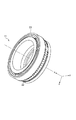
図1は本発明第1の実施形態における振動型駆動装置1の概略斜視図である。図1に示す振動型駆動装置を立体分解表示した概略斜視図を図2に示す。また、図1の振動型駆動装置の、x軸正方向から見た中心軸を通るy−z断面における断面図を図3(a)に示す。図3(a)において、円で囲ったB部及び、C部の拡大詳細図について、各々図3(b)、(c)に示す。 FIG. 1 is a schematic perspective view of a vibration type driving apparatus 1 according to a first embodiment of the present invention. FIG. 2 shows a schematic perspective view of the vibration type driving device shown in FIG. Further, FIG. 3A shows a cross-sectional view of the vibration type driving device of FIG. 1 in a yz section passing through the central axis viewed from the positive x-axis direction. In FIG. 3 (a), enlarged detail views of a B portion and a C portion surrounded by a circle are shown in FIGS. 3 (b) and 3 (c), respectively.
まず、振動型駆動装置1の構造及び、動作原理について説明する。2は弾性部材であり、裏面には、電気―機械エネルギ変換素子などの機械エネルギ付与素子が設けられる。例えば、圧電素子5が固着されている。電気基板9によって圧電素子5へ電気信号が伝達されると、圧電素子5は電気的エネルギを機械的エネルギへ変換し、アキシャル方向へ変位を生じる。圧電素子5を複数に分極し、弾性部材2の曲げ振動モードに合致した固有振動数を励起させることで、弾性部材2の上端面ではアキシャル方向の変位とそれに直交した駆動方向(図では周方向)の変位を得ることができる。また、弾性部材2には図に示すように、複数の溝をラジアル方向に設けることにより、より少ないエネルギで効率的に、より大きな変位を得ることが可能である。一方、図3(c)に示すように、弾性部材2の上端には溝が設けられ、そこに接触部材4が埋め込まれ、接触部材4の一端が弾性部材2に固着されている。接触部材4の他端は、被駆動部材3に接触している。被駆動部材3は弾性部3aをもち、弾性部材2のアキシャル方向の変位に倣うことで、弾性部材2の上端における2次元的な変位から、駆動方向(図では周方向)の変位を効率よく取り出せる機構としている。
First, the structure and operation principle of the vibration type driving device 1 will be described.
次に振動型駆動装置1における支持機構について説明する。弾性部材2は第1の支持部材6によって支持されている。第1の支持部材6は、120度間隔でラジアル方向に保持機構6aを備え、図3(b)に示すように、保持機構6aが弾性部材2の溝に嵌め込まれることで、弾性部材2をラジアル方向に拘束、支持している。電気基板9、圧電素子5及び弾性部材が一体となったユニットは、支持部材6の上に配置された不織布10の上に保持されている。図中、保持機構6aは、第1の支持部材6の一部として示してあるが、弾性部材2の第1の支持部材6への組み込み容易性を考慮して、第1の支持部材6と保持機構6aとを別体として形成するなど、第1の支持部材6を2体以上から形成することができる。
Next, a support mechanism in the vibration type driving device 1 will be described. The
次に、被駆動部材3の支持方法について説明する。7は、被駆動部材3を支持する第2の支持部材である。第2の支持部材7は、外輪7a、内輪7b、複数の玉7cで構成されるラジアル玉軸受である。被駆動部材3と第2の支持部材7は、外輪7aの外径嵌合によって支持されている。内輪7bの上端部と、加圧部材8に設けられた弾性部8aとは接触状態にあり、加圧部材8の外周に設けられた雄ねじ8bと第1の支持部材6の内周に設けられた雌ねじ6bを締め付けることによって、弾性部8aを弾性変形させる。加圧部材8は、弾性部材2および被駆動部材3の少なくとも一方を接触部材4へ接触加圧する部材であり、この弾性変形を利用することで、アキシャル方向に適切な荷重で加圧することができる。このように、被駆動部材3を接触部材4側へ適切な荷重で加圧することで、駆動に適した良好な摩擦特性を得ることができる。
Next, a method for supporting the driven
本実施形態の振動型駆動装置において、弾性部材2、被駆動部材3、接触部材4が非金属材料から成る。たとえば、弾性部材2をセラミックス、被駆動部材3を樹脂で形成し、接触部材4を樹脂または非酸化物系セラミックスで形成する。なお、弾性部材及び接触部材の両方をセラミックスで形成した場合は、セラミックスが水分を吸着することにより、弾性部と接触部材との間の摩擦特性が安定せず、振動型駆動装置としての性能に悪影響を及ぼすことがある。従って、接触部材を摺動性の良い、強化プラスチック(FRP)等の樹脂やシリコンカーバイド等の非酸化物系セラミックス、非酸化物系セラミックス等が充填剤として添加されたセラミックスで形成することにより、安定した摩擦特性が得られる効果がある。
In the vibration type driving device of the present embodiment, the
また、上記に加え、第1の支持部材6及び第2の支持部材7、及び加圧部材8は非金属材料、例えばセラミックスや樹脂から成る。
In addition to the above, the
本発明の振動型駆動装置において、圧電素子の電極や電気基板の配線以外は、非金属材料から成るため、磁場の発生している空間において本発明の振動型駆動装置を使用したとしても、磁場の乱れが発生しない、または、発生したとしても低減されたものとなる。したがって、磁場を乱すことなく振動型駆動装置により物体の位置を移動したり制御したりすることができる。 In the vibration type driving device of the present invention, since the electrodes other than the electrodes of the piezoelectric element and the wiring of the electric substrate are made of a non-metallic material, even if the vibration type driving device of the present invention is used in a space where a magnetic field is generated, the magnetic field Disturbance does not occur or even if it occurs. Therefore, the position of the object can be moved or controlled by the vibration type driving device without disturbing the magnetic field.
例えば、本発明における振動型駆動装置を、磁気共鳴イメージング装置近傍または内部で用いる場合、磁気共鳴イメージング装置の画像形成に影響を与えずに、または影響が低減された画像形成を行うことができる。 For example, when the vibration type driving device according to the present invention is used in the vicinity of or inside the magnetic resonance imaging apparatus, it is possible to perform image formation without affecting or reducing the image formation of the magnetic resonance imaging apparatus.
本実施形態の振動型駆動装置1の各構成部材の材料について、具体例を説明する。まず、弾性部材2の材料について述べる。本実施の形態では、弾性部材として、セラミックや樹脂を用いることができる。樹脂としては、強化プラスチック(FRP)として、充填剤が添加された樹脂を用いることができ、例えば、ポリエーテルエーテルケトン(PEEK)にグラスファイバーやカーボンファイバーなどの充填剤が添加された材料を用いることができる。本実施の形態では、ファインセラミックの一種である、立方晶中に一部正方晶を分散・析出させ、熱間静水圧加圧焼結法(HIP)によって焼結させた部分安定化ジルコニア(PSZ:Partially Stabilized Zirconia)を用いる。安定化ジルコニア(SZ:Stabilized Zirconia)は、耐熱材料として用いられている。安定化ジルコニアは、ジルコニア(ZrO2)に酸化マグネシウム(MgO)や、イットリア(Y2O3)、酸化カルシウム(CaO)等が固溶させることによって、低温状態でも立方晶を維持する。一方、部分安定化ジルコニア(PSZ)では、正方晶を準安定相として含有させる。このため、酸化マグネシウム(MgO)やイットリア(Y2O3)の少なくとも一方を、ジルコニア(ZrO2)を安定化ジルコニア(SZ)として安定化させるのに必要な量よりも少ない量添加し、適切な熱処理を行う。これによって、ジルコニアを部分的に安定させることが可能である。強度を増すために、アルミナ(Al2O3)を固溶していてもよい。部分安定化ジルコニアを採用することで、応力場における亀裂先端の破壊エネルギが、正方晶から単斜晶へのマルテンサイト変態により吸収されるため、ファインセラミックスでも高い靱性を得られる利点がある。また、弾性部材として、アルミナ(Al2O3)を適用することも可能である。参考までに市販の純度99.5[%]のアルミナ(Al2O3)と、イットリア(Y2O3)が添加され熱間静水圧加圧焼結法(HIP)によって焼結された部分安定化ジルコニア(PSZ)を用いて、弾性部材を形成した場合について、シミュレーション結果をもとに性能比較を行う。シミュレーションは、溝幅1.0[mm]、溝底半径R0.2[mm]をもつ外径約φ60[mm]、高さ約5[mm]の弾性部材にある曲げ振動モードを想定したPeek to Peekで振幅2[μm]の強制変位を与えることにより行った。市販されている99.5[%]のアルミナ(Al2O3)と部分安定化ジルコニア(PSZ)、各々の材料で弾性部材を形成した時の弾性部材に生じる最大主応力を求めたシミュレーション結果を表1に示す。表1において、各材料の特性値は、概略参考値であり、保証値ではない。表1よりアルミナ(Al2O3)では、最大主応力が静的な抗折力の約21[%]であるのに対し、部分安定化ジルコニア(PSZ)では、最大主応力が静的な抗折力の約2.6[%]であることがわかる。弾性部材2には、ラジアル方向に周期的な曲げ振動を繰り返し励起するため、弾性部材に生じる最大主応力が静的な抗折力に比べて非常に小さいことが望ましい。セラミックスは脆性材料のため、弾性部材に用いるのに適した、抗析力に対する最大主応力の割合を定義することは困難であるが、一つの指標として煉瓦や石材におけるアンウィン(Unwin)の安全率を参考にする。アンウィンの安全率において、動的な繰り返し荷重が作用する場合は、安全率約30が目安とされている。表1におけるシミュレーション結果から求めると、アルミナの場合が安全率約4.7、部分安定化ジルコニア(PSZ)の場合が安全率約37に相当し、部分安定化ジルコニア(PSZ)の方がより適切な材料であると判断できる。
A specific example of the material of each constituent member of the vibration type driving device 1 of the present embodiment will be described. First, the material of the
部分安定化ジルコニア(PSZ)は、比重がマルテンサイト系ステンレス鋼SUS420J2の約79[%]程度と、樹脂やアルミナ(Al2O3)などのセラミックス材料と比べて、高比重である。よって、弾性部材として、ファインセラミックスの中でも部分安定化ジルコニア(PSZ)を用いることで、より大きな振動エネルギを得ることができ、また、樹脂と比較して粘性損失が少ないため、非金属材料の中でも良好な振動特性を得ることができる。 Partially stabilized zirconia (PSZ) has a specific gravity of about 79% of martensitic stainless steel SUS420J2 and a high specific gravity compared to ceramic materials such as resin and alumina (Al 2 O 3 ). Therefore, by using partially stabilized zirconia (PSZ) among the fine ceramics as the elastic member, a larger vibration energy can be obtained, and since there is less viscous loss compared to the resin, among non-metallic materials Good vibration characteristics can be obtained.

次に、被駆動部材3の材料とその製造方法について説明する。先に述べたように、被駆動部材は、図中z方向において安定した弾性特性を有することが必要である。また、振動型駆動装置の良好な制御特性を得るために、弾性部材の曲げ振動に追従する振動モードに合致した被駆動部材の固有振動数は、弾性部材の、曲げ振動に合致した固有振動数よりも十分高い必要がある。以上の2点に鑑みて、被駆動部材は充填剤を添加した樹脂を用いて形成することができ、例えば、ポリエーテルエーテルケトン(PEEK)にグラスファイバーやカーボンファイバーなどの充填剤が添加された強化プラスチック(FRP)を用いて形成できる。充填剤として添加されたグラスファイバー(GF)やカーボンファイバー(CF)は硬質な耐摩耗性材料としても作用し、安定した摩擦力を確保するのにも寄与する。その他、摺動性の向上のためにポリテトラフルオロエチレン(PTFE)などのフッ素系樹脂やポリイミド(PI)等の耐熱性樹脂を含有してもよい。また、摩擦力向上のために、セラミックスまたは樹脂材料にシリコンカーバイド(SiC)やチタンカーバイド(TiC)等の非酸化物系セラミックスを含有してもよい。接触部材の表層としては、ダイアモンドライクカーボン(DLC)等の非金属材料や、前記シリコンカーバイド(SiC)やチタンカーバイド(TiC)等の非酸化物セラミックスから成る被膜が形成されていてもよい。通常市販されている強化プラスチックを使用して被駆動部材を形成する場合、切削加工あるいは射出成形によって製作するのが一般的である。図中に示した円環状の被駆動部材を、前者の切削加工により製作する場合、市販のFRPから成るバー材を用いて加工するのが一般的である。しかし、バー材の多くは押し出し成形によって製作されているため、充填剤の配向が押し出し方向に揃い、剛性の異方性を生じやすい。加えて、ラジアル方向にも充填剤の密度が異なり、設計に対する特性誤差を生じやすい。また、射出成型によって、円環状の被駆動部材を製作する場合は、金型のゲートを起点とした不均一分散が起こりやすく、同様に剛性の異方性を生じやすい。従って本実施の形態では、次の手順に従い被駆動部材を製作する。まず、粒体状の樹脂と充填剤の繊維を予め均一に混合した後、円筒状の金型に入れて加熱しながら圧縮成形を施し、形成する被駆動部材より大きい寸法の円柱(円盤)状のブランク材を成形する。次に、圧縮成形によって製作されたブランク材を旋盤加工などの機械加工によって所定の寸法に仕上げる。このような手順に従うと、強化プラスチックの充填剤を均一に分散させることができ、弾性部3aの弾性特性を精度よく設計することが可能である。設計例として、被駆動部材として従来から用いられているA5056などのアルミ系金属を用いた場合と同等の弾性機能を、弾性部3aに付与する場合を考える。グラスファイバーを30[%]添加したポリエーテルエーテルケトン(PEEK)は、アルミニウム系金属A5056の約14[%]のヤング率を持つ。被駆動部材の材料として、このグラスファイバーが添加されたPEEKを用いた場合、弾性部3aのz方向の厚さ寸法を、駆動周波数に応じて設計することで、A5056と同等の弾性特性が得られる。このように、充填剤を均一に分散させることにより弾性特性の精度を向上させる効果が期待できる。また、充填剤の添加により、クリープ時間を拡大させる効果が期待できる。本実施の形態では、粒体状の樹脂と充填剤を予め混合した後に圧縮成形したものをブランク材として利用する製作例について説明した。しかし、このような方法が適用困難な場合でも、次のような方法で、充填剤を添加した強化プラスチック(FRP)の異方性を簡易的に改善させることが可能である。市販のバー材や管材、その他の資材をブランク成形用の金型に入れ、加熱しながらゆっくり圧縮成形を施すことで、揃っていた充填剤の配向を分散させる効果が期待できる。
Next, the material of the driven
次に、加圧部材8の材料について説明する。本実施の形態における加圧部材8は弾性部8aを備えており、その弾性を第2の支持部材7の予圧と、弾性部材2−接触部材4−被駆動部材3間の接触圧力の管理に利用していることから、弾性部8aは高精度な弾性特性を持つことが要求される。例えば、弾性部8aは樹脂を用いて形成することができ、一般的なエンジニアリングプラスチックを用いて加圧部材8を形成すれば、異方性の少ない弾性特性が得られる。更に、被駆動部材3と同様に充填剤が添加された強化プラスチック(FRP)を用いると、良好なクリープ特性を得ることができる。
Next, the material of the
最後に、圧電素子5、第1の支持部材6、第2の支持部材7、接触部材4の材料について説明する。圧電素子5としては、圧電層にセラミック等の非磁性体を用いることができ、例えばジルコン酸鉛とチタン酸鉛(PbZrO3−PbTiO3)を主成分とする圧電素子を用いることが出来る。また、第1の支持部材6は樹脂やセラミックスを用いて形成することができ、高精度な弾性特性や、高い耐熱性が要求されないため、例えば、エンジニアリングプラスチックや、マシナブルセラミックス、ファインセラミックスなどの非金属材料の適用が可能である。第2の支持部材7については、外輪7a及び、内輪7bは樹脂やセラミックスを用いて形成することができ、エンジニアリングプラスチックや、マシナブルセラミックス、ファインセラミックスなどの非金属材料の適用が可能である。玉7cは、セラミックス等の非金属材料を用いて形成することができるが、部分安定化ジルコニアを用いて形成すると、靱性、耐熱性、耐摩耗性に優れた玉7cを形成することができる。また、接触部材4は非金属である樹脂を用いて形成することができる。摺動性を向上させる目的から、接触部材4の材料としては、フッ素系樹脂のポリテトラフルオロエチレン(PTFE)が好ましい。また、樹脂としては、セラミックス等の充填剤が添加された樹脂を用いてもよい。たとえば、シリコンカーバイド(SiC)やチタンカーバイド(TiC)等の非酸化物系セラミックスを含有した樹脂を用いることができる。ポリイミド(PI)等の耐熱性樹脂を含有してもよい。また、摩擦力向上のために、セラミックスに、シリコンカーバイド(SiC)やチタンカーバイド(TiC)等の非酸化物系セラミックスを含有してもよい。接触部材の表層として、硬質な摩擦層である、ダイアモンドライクカーボン(DLC)やシリコンカーバイド(SiC)、チタンカーバイド(TiC)等の非酸化物系セラミックスから成る被膜を形成してもよい。
Finally, materials of the
本実施の形態において、各部材の適切な材料について説明してきたが、本発明における振動型駆動装置は上述の材料に限定されるものではなく、各部材は、非金属材料により構成されていることを満たしていればよい。ただし、上述のように、弾性部材と被駆動体の両方がセラミックスから成る場合、接触部材を、ポリテトラフルオロエチレン(PTFE)などのフッ素系樹脂やポリイミド(PI)等の耐熱性樹脂を含有した樹脂で形成することで、良好な摺動性が確保できる。さらに、接触部材として、セラミックスまたは樹脂材料にシリコンカーバイド(SiC)やチタンカーバイド(TiC)等の非酸化物系セラミックスを含有することで、安定した摩擦特性を得る効果が期待できる。 In the present embodiment, an appropriate material for each member has been described. However, the vibration type driving device according to the present invention is not limited to the above-described material, and each member is made of a non-metallic material. As long as However, as described above, when both the elastic member and the driven body are made of ceramics, the contact member contains a fluorine resin such as polytetrafluoroethylene (PTFE) or a heat resistant resin such as polyimide (PI). Good slidability can be ensured by forming the resin. Furthermore, by containing non-oxide ceramics such as silicon carbide (SiC) or titanium carbide (TiC) in the ceramic or resin material as the contact member, an effect of obtaining stable friction characteristics can be expected.
ここで、非金属材料とは金属結合以外からなる材料、すなわち、イオン結合、共有結合、または分子間力をもとに構成されている材料を指す。また、ある部材がAから成る、Aから形成される、とは、Aのみから構成されることに限定されず、実質的にAからなる場合を含む。従って、本実施形態において、例えば磁気共鳴イメージング装置の画像形成に実質的な影響を与えない程度に、ある部材に他の元素や材料等が混入している場合も含む。 Here, the non-metallic material refers to a material other than a metal bond, that is, a material configured based on an ionic bond, a covalent bond, or an intermolecular force. In addition, the fact that a certain member is made of A and formed of A is not limited to being made of only A, but includes a case of being substantially made of A. Therefore, in this embodiment, for example, the case where other elements, materials, and the like are mixed in a certain member to the extent that does not substantially affect the image formation of the magnetic resonance imaging apparatus is included.
本実施の形態では、機械エネルギ付与素子の一例として電気―機械エネルギー変換素子の一例である圧電素子を用いたが、これに限定されず、磁歪効果を利用した機械エネルギ付与素子を用いてもよい。また、機械エネルギ付与素子は、電気エネルギや磁気エネルギを機械エネルギに変換するものに限定されず、流体や熱等のもつエネルギを機械エネルギに変換するものであってもよい。 In this embodiment, a piezoelectric element which is an example of an electro-mechanical energy conversion element is used as an example of a mechanical energy applying element. However, the present invention is not limited to this, and a mechanical energy applying element using a magnetostrictive effect may be used. . Further, the mechanical energy applying element is not limited to one that converts electrical energy or magnetic energy into mechanical energy, and may be one that converts energy such as fluid or heat into mechanical energy.
本実施の形態では、円環状の回転駆動型の振動型駆動装置に関する実施の形態について記載したが、中実状の回転型駆動装置や、直動駆動型、面内駆動型、球状駆動型の振動型駆動装置への適用も容易に実施可能である。 In the present embodiment, an embodiment related to an annular rotational drive type vibration type drive device has been described. However, a solid rotary type drive device, a direct drive type, an in-plane drive type, and a spherical drive type vibration are described. It can be easily applied to a mold drive device.
(実施の形態2)
図4乃至図6を用いて、本発明の第2の実施形態について説明する。尚、図中に示した座標軸は、共通のものとする。また、実施の形態1と共通する箇所は説明を省略し、共通する部品は同一の符号を用いて説明する。
(Embodiment 2)
A second embodiment of the present invention will be described with reference to FIGS. The coordinate axes shown in the figure are common. Further, the description of the parts common to the first embodiment will be omitted, and common parts will be described using the same reference numerals.
図4は本発明第2の実施形態における振動型駆動装置21の概略斜視図である。図4に示す振動型駆動装置21を立体分解表示した概略斜視図を図5に示す。また、図4の振動型駆動装置の、x軸正方向から見た中心軸を通るy−z断面における断面図を図6(a)に示す。図6(a)において、円で囲ったD部の拡大詳細図について、図6(b)に示す。
FIG. 4 is a schematic perspective view of the vibration
まず、振動型駆動装置21の構造及び、動作原理について説明する。22は弾性部材であり、裏面には機械エネルギ付与素子が設けられる。例えば、電気―機械エネルギ変換素子である、圧電素子5が固着されている。実施の形態1と同様に、弾性部材22の曲げ方向の振動モードに合致した固有振動数を励起させることで、弾性部材22の上端面ではアキシャル方向の変位とそれに直交した駆動方向(図では周方向)の変位を得ることができる。一方、図6(b)に示すように、接触部材24の上端は、被駆動部材23に固着され、下端は弾性部材22の上端に接触している。接触部材24は弾性部24aをもち、弾性部材22のアキシャル方向の変位に倣うことで、弾性部材22の上端における2次元的な変位から、駆動方向(図では周方向)の変位を効率よく取り出せる機構としている。
First, the structure and operation principle of the vibration
次に振動型駆動装置21における支持機構について説明する。弾性部材22は第1の支持部材6によって支持され、被駆動部材23は第2の支持部材7によって支持され、支持方法は実施の形態1と同様とする。
Next, the support mechanism in the vibration
本実施の形態の振動型駆動装置21においても、圧電素子の電極や電気基板の配線以外は、非金属材料から成る。したがって、磁場の発生している空間において本発明の振動型駆動装置を使用したとしても、磁場の乱れが発生しない、または、発生したとしても低減されたものとなる。従って、例えば、本実施の形態における振動型駆動装置21を、磁気共鳴イメージング装置のガントリー近傍または内部で用いる場合、磁気共鳴イメージング装置の画像形成に影響を与えずに、または影響が低減された画像形成を行うことができる。本実施の形態で用いる非金属材料の具体例について、以下に説明する。
The vibration
まず、弾性部材22の材料について述べる。弾性部材22の材料としては、樹脂やセラミックス等を用いることができる。本実施の形態においては、実施の形態1と同様に、熱間静水圧加圧焼結法(HIP)によって焼結させた部分安定化ジルコニア(PSZ:Partially Stabilized Zirconia)を用いる。
First, the material of the
次に、被駆動部材23の材料について説明する。本実施の形態において、被駆動体部材はセラミックからなる。被駆動部材は、実施の形態1でも説明したように、良好な制御特性を得るために、弾性部材の曲げ振動に追従する振動モードに合致した被駆動部材の固有振動数が、弾性部材の曲げ振動に合致した固有振動数よりも十分高い必要がある。従って、例えば、弾性部材よりも比重が小さく、ヤング率の高い純度99.5[%]のアルミナ(Al2O3)を使用する。
Next, the material of the driven
次に、接触部材24の材料について説明する。接触部材24は、樹脂などの非金属を用いて形成することができる。接触部材24については、弾性部24aの高精度な弾性特性及び、弾性部材22に対する摺動性が求められるため、樹脂としては、充填剤が添加された樹脂を用いることができる。例えば、接触部材24は、グラスファイバーやカーボンファイバー等の充填剤が均一に分散された強化プラスチックを用いて形成される。接触部材24の形成方法としては、粒体状の樹脂と、上記充填剤とを混合した後、圧縮成形することにより成形することができる。樹脂には、例えば、ポリフェニレンサルファイド樹脂(PPS)や、ポリエーテルエーテルケトン(PEEK)を用いる。充填剤として添加されたグラスファイバー(GF)やカーボンファイバー(CF)は硬質な耐摩耗性材料としても作用し、安定した摩擦力の確保にも寄与する。また、充填剤として、セラミックスが添加された樹脂を用いることもできる。たとえば、摩擦力向上の観点から、シリコンカーバイド(SiC)やチタンカーバイド(TiC)等の非酸化物系セラミックスを含有した樹脂を用いることができる。その他、摺動性の向上のためにポリテトラフルオロエチレン(PTFE)などのフッ素系樹脂やポリイミド(PI)等の耐熱性樹脂を含有してもよい。また、摩擦力向上のために、セラミックスにシリコンカーバイド(SiC)やチタンカーバイド(TiC)等の非酸化物系セラミックスを含有した材料を用いてもよい。更に、接触部材の表層として、硬質な摩擦層である、ダイアモンドライクカーボン(DLC)やシリコンカーバイド(SiC)、チタンカーバイド(TiC)等の非酸化物系セラミックスから成る被膜を形成してもよい。
Next, the material of the
また、圧電素子5、電気基板9、不織布10、第1の支持部材6、第2の支持部材7、及び加圧部材8の材料に関しては、実施の形態1と同様のものを用いることができる。
In addition, regarding the materials of the
本実施の形態における振動型駆動装置21は、実施の形態1と比較して、被駆動部材23を高剛性に形成することができるため、被駆動部材23の良好な制御性を確保できる。また、接触部材24をセラミックスで形成してもよい。しかし、弾性部材22及び接触部材24の両方をセラミックスで形成した場合は、セラミックスが水分を吸着することにより、弾性部材22と接触部材24との間の摩擦特性が安定せず、振動型駆動装置としての性能に悪影響を及ぼすことがある。従って、弾性部材22、及び被駆動部材23をセラミックスで、接触部材24を、強化プラスチック(FRP)等の充填剤が添加された樹脂で形成することで、高精度な弾性特性を確保しつつ、充填剤が硬質な耐摩耗性材料として機能するため、摩擦力も確保できる。また接触部材24に、ポリテトラフルオロエチレン(PTFE)などのフッ素系樹脂やポリイミド(PI)等の耐熱性樹脂を含有することで、良好な摺動性が確保できる。さらに、セラミックスまたは樹脂材料にシリコンカーバイド(SiC)やチタンカーバイド(TiC)等の硬質非酸化物系セラミックスを含有したり、これらの材料から成る被膜を形成したりすることで、安定した摩擦特性を得る効果が期待できる。
The vibration
本実施の形態では、図6(b)の図中Eで示したx−y平面に平行な平面を境に、被駆動部材23と接触部材24が各々形成されているが、図中で示したEと異なる箇所で、被駆動部材23と接触部材24が固着されていても良い。本実施の形態では、被駆動部材23がセラミックスで形成されている例について記載したが、被駆動部材23が強化プラスチック(FRP)等の非金属材料で構成されていてもよい。また、被駆動部材23と接触部材24が同一部材から成る場合や、同一部材が一体で形成されている場合も本発明の範疇に含まれる。
In the present embodiment, the driven
本実施の形態では、機械エネルギ付与素子の一例として電気―機械エネルギー変換素子の一例である圧電素子を用いたが、これに限定されず、磁歪効果を利用した機械エネルギ付与素子を用いてもよい。また、機械エネルギ付与素子は、電気エネルギや磁気エネルギを機械エネルギに変換するものに限定されず、流体や熱等のもつエネルギを機械エネルギに変換するものであってもよい。 In this embodiment, a piezoelectric element which is an example of an electro-mechanical energy conversion element is used as an example of a mechanical energy applying element. However, the present invention is not limited to this, and a mechanical energy applying element using a magnetostrictive effect may be used. . Further, the mechanical energy applying element is not limited to one that converts electrical energy or magnetic energy into mechanical energy, and may be one that converts energy such as fluid or heat into mechanical energy.
また、本実施の形態では、円環状の回転駆動型の振動型駆動装置に関する実施の形態について記載したが、中実状の回転型駆動装置や、直動駆動型、面内駆動型、球状駆動型の振動型駆動装置への適用も容易に実施可能である。 Further, in the present embodiment, an embodiment related to an annular rotational drive type vibration type drive device has been described, but a solid rotary type drive device, a linear motion drive type, an in-plane drive type, a spherical drive type The present invention can be easily applied to the vibration type driving device.
(実施の形態3)
図7乃至図9を用いて、本発明の第3の実施形態について説明する。尚、図中に示した座標軸は、共通のものとする。また、実施の形態1及び実施の形態2と共通する箇所は説明を省略し、共通する部品は同一の符号を用いて説明する。
(Embodiment 3)
A third embodiment of the present invention will be described with reference to FIGS. The coordinate axes shown in the figure are common. Also, description of parts common to the first and second embodiments will be omitted, and common parts will be described using the same reference numerals.
図7は本発明第3の実施形態における振動型駆動装置31の概略斜視図である。図7に示す振動型駆動装置を立体分解表示した概略斜視図を図8に示す。また、図7の振動型駆動装置の、x軸正方向から見た中心軸を通るy−z断面における断面図を図9(a)に示す。図9(a)において、円で囲ったF部の拡大詳細図について、図9(b)に示す。
FIG. 7 is a schematic perspective view of the vibration
まず、振動型駆動装置31の構造及び、動作原理について説明する。22は弾性部材であり、裏面には機械エネルギ付与素子が設けられる。例えば、電気―機械エネルギ変換素子である、圧電素子5が固着されている。実施の形態1と同様に、弾性部材22の曲げ方向の振動モードに合致した固有振動数を励起させることで、弾性部材2の上端面ではアキシャル方向の変位とそれに直交した駆動方向(図では周方向)の変位を得ることができる。一方、図9(b)に示すように、薄膜状の接触部材34の上端は、被駆動部材33に固着され、下端は弾性部材22の上端に接触している。被駆動部材33は弾性部33aをもち、弾性部材22のアキシャル方向の変位に倣うことで、弾性部材22の上端における2次元的な変位から、駆動方向(図では周方向)の変位を効率よく取り出せる機構としている。
First, the structure and operation principle of the vibration
次に振動型駆動装置31における支持機構について説明する。弾性部材22は第1の支持部材6によって支持され、被駆動部材23は第2の支持部材7によって支持され、支持方法は実施の形態1と同様とする。
Next, a support mechanism in the vibration
本実施の形態の振動型駆動装置31においても、圧電素子の電極や電気基板の配線以外は、非金属材料から成る。したがって、磁場の発生している空間において本発明の振動型駆動装置を使用したとしても、磁場の乱れが発生しない、または、発生したとしても低減されたものとなる。よって、例えば、本実施の形態における振動型駆動装置31を、磁気共鳴イメージング装置のガントリー近傍または内部で用いる場合、磁気共鳴イメージング装置の画像形成に影響を与えずに、または影響が低減された、画像形成を行うことができる。本実施の形態で用いる非金属材料の具体例について、以下に説明する。
The vibration
まず、弾性部材22の材料としては、樹脂やセラミックス等を用いることができる。本実施の形態において、弾性部材22は、実施の形態2と同様に、熱間静水圧加圧焼結法(HIP)によって焼結させた部分安定化ジルコニア(PSZ:Partially Stabilized Zirconia)を用いる。
First, as the material of the
次に、被駆動部材33も、セラミックスである、高靱性の部分安定化ジルコニア(PSZ)を用いる。
Next, the to-
接触部材34は、樹脂、非酸化物系セラミックス、または充填剤として非酸化物系セラミックスが添加されたセラミックスからなり、例えば、摺動性を向上させる目的から、フッ素系樹脂のポリテトラフルオロエチレン(PTFE)を用いて形成することができる。またポリイミド(PI)等の耐熱性樹脂を含有してもよい。セラミックスまたは樹脂にシリコンカーバイド(SiC)やチタンカーバイド(TiC)等の非酸化物系セラミックスを含有させることで、摩擦力を向上させることができる。また、接触部材の表層として、硬質な摩擦層である、ダイアモンドライクカーボン(DLC)やシリコンカーバイド(SiC)、チタンカーバイド(TiC)等の非酸化物系セラミックスから成る被膜を形成してもよい。
The
また、圧電素子5、電気基板9、不織布10、第1の支持部材6、第2の支持部材7、及び加圧部材8の材料に関しては、実施の形態1と同様のものを用いることができる。
In addition, regarding the materials of the
本実施の形態における振動型駆動装置31は、被駆動部材33を高靱性に形成することができるため、被駆動部材33の良好な弾性特性を確保できる。本実施の形態では、弾性部材22と被駆動部材33とを、ともに部分安定化ジルコニア(PSZ)で形成しているため、両者を直接接触させると水分の吸着により、安定した摩擦特性が得られないため、振動型駆動装置の性能に悪影響を及ぼすことがある。そこで、本実施の形態のように、弾性部材22と被駆動部材33との間に接触部材34を設けることにより、良好な摺動性を確保することができる。
Since the driven
本実施の形態では、被駆動部材33がセラミックスで形成されている例について記載したが、被駆動部材33が強化プラスチック(FRP)等の非金属材料で構成されていてもよい。接触部材は、ポリテトラフルオロエチレン(PTFE)であることが望ましいが、ポリイミド(PI)等の耐熱性樹脂を含有してもよい。また、摩擦力向上のために、シリコンカーバイド(SiC)やチタンカーバイド(TiC)等の非酸化物系セラミックスが充填剤として添加された、セラミックスや樹脂から形成されてもよい。接触部材の表層として、硬質な摩擦層である、ダイアモンドライクカーボン(DLC)やシリコンカーバイド(SiC)、チタンカーバイド(TiC)等の非酸化物系セラミックスから成る被膜を形成してもよい。また、被駆動部材33、接触部材34が同一部材から成る場合や、同一部材が一体で形成されている場合も本発明の範疇に含まれる。
In the present embodiment, an example in which the driven
本実施の形態では、機械エネルギ付与素子の一例として電気―機械エネルギー変換素子の一例である圧電素子を用いたが、これに限定されず、磁歪効果を利用した機械エネルギ付与素子を用いてもよい。また、機械エネルギ付与素子は、電気エネルギや磁気エネルギを機械エネルギに変換するものに限定されず、流体や熱等のもつエネルギを機械エネルギに変換するものであってもよい。 In this embodiment, a piezoelectric element which is an example of an electro-mechanical energy conversion element is used as an example of a mechanical energy applying element. However, the present invention is not limited to this, and a mechanical energy applying element using a magnetostrictive effect may be used. . Further, the mechanical energy applying element is not limited to one that converts electrical energy or magnetic energy into mechanical energy, and may be one that converts energy such as fluid or heat into mechanical energy.
また、本実施の形態では、円環状の回転駆動型の振動型駆動装置に関する実施の形態について記載したが、中実状の回転型駆動装置や、直動駆動型、面内駆動型、球状駆動型の振動型駆動装置への適用も容易に実施可能である。 Further, in the present embodiment, an embodiment related to an annular rotational drive type vibration type drive device has been described, but a solid rotary type drive device, a linear motion drive type, an in-plane drive type, a spherical drive type The present invention can be easily applied to the vibration type driving device.
(実施の形態4)
本実施の形態では、本発明の振動型駆動装置の応用例を示す。本発明の振動型駆動装置は、磁気共鳴イメージング装置の内部で用いる医療装置に用いることができる。また、本発明の振動型駆動装置を用いて、磁気共鳴イメージング装置内部で使用可能な医療装置を有する、医療システムを提供することができる。
(Embodiment 4)
In this embodiment, an application example of the vibration type driving device of the present invention is shown. The vibration type driving device of the present invention can be used for a medical device used inside a magnetic resonance imaging apparatus. Moreover, the medical system which has a medical device which can be used inside a magnetic resonance imaging apparatus can be provided using the vibration type drive device of this invention.
医療システムにおいて、磁気共鳴イメージング装置内部に、本発明の振動型駆動装置を有する医療装置を設置する。本実施の形態において、医療装置は、医療器具と、医療器具を保持し、移動可能に構成された保持部と、保持部に取り付けられ、保持部を移動する振動型駆動装置とを備える。このような構成とすることで、磁気共鳴イメージング装置によって、患者の画像取得情報を取得しながら、医療装置により医療処置を行うことができる。 In a medical system, a medical device having the vibration type driving device of the present invention is installed inside a magnetic resonance imaging apparatus. In the present embodiment, the medical device includes a medical instrument, a holding unit configured to hold and move the medical instrument, and a vibration type driving device that is attached to the holding unit and moves the holding unit. With such a configuration, a medical procedure can be performed by the medical device while acquiring image acquisition information of the patient by the magnetic resonance imaging apparatus.
図10及び図11を用いて、磁気共鳴イメージング装置の内部で用いられる医療装置として医療用マニピュレータ、固定部としてアーム、医療器具としてエンドエフェクタを用いる例について説明する。なお、医療器具はこれに限定されず、例えば、メス、鉗子、ニードル、プローブ、及び診断用の器具などが含まれる。 An example in which a medical manipulator is used as a medical device used inside a magnetic resonance imaging apparatus, an arm is used as a fixing unit, and an end effector is used as a medical instrument will be described with reference to FIGS. In addition, a medical instrument is not limited to this, For example, a scalpel, forceps, a needle, a probe, a diagnostic instrument, etc. are included.
図10は、本発明の医療用マニピュレータ50を設置した、磁気共鳴イメージング装置40を模式的に示した概略斜視図である。ここでは、磁気共鳴イメージング装置として、ダブルドーナツ型のオープン磁気共鳴イメージング装置を用いた例を示す。図10において、42は患者を寝かせるための処置台、43は、処置台42の保持部、41a、41bは磁気共鳴イメージング装置の構成要素である磁石であり、ここでは円筒形状を有する。円筒形磁石41a、41bの間には、マニピュレータ50を設置するためのマニピュレータ設置台44が設置されている。円筒形磁石41a、41bの間にマニピュレータ50を設置しているため、磁気共鳴イメージング装置による画像取得情報を取得しながら、マニピュレータ50による医療処置を可能としている。
FIG. 10 is a schematic perspective view schematically showing a magnetic
次に、医療用マニピュレータ50の詳細構造について、図11を用いて説明する。医療用マニピュレータ50は、各々回転1自由度をもつ、第1関節61、第2関節62、第3関節63、第4関節64を介して、第1アーム53、第2アーム54、第3アーム55、第4アーム56を備えた4軸垂直多関節アームの構造を有する。各々の関節には、実施の形態1乃至3に示した、弾性部材等を支持する第1の支持部材、被駆動部材等を支持する第2の支持部材を備えた、振動型駆動装置51a〜51gが配置され、各関節に駆動トルクを付与することができる。また、第4アームの先端にはエンドエフェクタ57が装着され、穿刺や焼灼、把持等の任意の医療処置を行う。
Next, the detailed structure of the
次に、各振動型駆動装置の取り付け構造について説明する。振動型駆動装置51aの第1の支持部材は、マニピュレータ基台52に固定され、第2の支持部材は第1アーム53に固定され、振動型駆動装置51aは第1関節61まわりの回転トルクを付与可能な構造である。振動型駆動装置51b及び51cの第1の支持部材は、ともに第1アーム53に固定され、振動型駆動装置51b及び51cの第2の支持部材は、ともに第1アーム54に固定される。振動型駆動装置51b及び51cは第2関節62まわりの回転トルクを付与可能な構造である。振動型駆動装置51d及び51eの第1の支持部材は、ともに第2アーム54に固定され、振動型駆動装置51d及び51eの第2の支持部材は、ともに第3アーム55に固定される。振動型駆動装置51d及び51eは第3関節63まわりの回転トルクを付与可能な構造である。振動型駆動装置51f及び51gの第1の支持部材は、ともに第3アーム55に固定され、振動型駆動装置51f及び51gの第2の支持部材は、ともに第4アーム56に固定される。振動型駆動装置51f及び51gは第4関節64まわりの回転トルクを付与可能な構造である。
Next, the mounting structure of each vibration type driving device will be described. The first support member of the vibration
次に、医療用マニピュレータ50の材料について説明する。振動型駆動装置51a〜51gには、実施の形態1乃至3の振動型駆動装置のいずれかを用いている。従って、振動型駆動装置51a〜51gは、各々の電気基板や電極を除くすべての部材が非金属材料から成っている。また、マニピュレータ基台52、第1アーム53、第2アーム54、第3アーム55、第4アーム56は、すべて、非金属材料やベリリウム銅等の金属非磁性材料といった、非磁性材料から成っている。
Next, the material of the
従って、本実施の形態によれば、医療用マニピュレータを磁気共鳴イメージング装置の円筒形磁石の近傍に安全に設置することができる。さらに磁気共鳴イメージング装置の磁場への影響を最小限に抑えた医療用マニピュレータを提供することができる。そのため、磁気共鳴イメージング装置による取得画像に対するアーチファクトを最小限に抑えることが可能である。本発明の振動型駆動装置を医療用マニピュレータの関節へ直接配置することで、歯車やベルトなどの動力伝達機構を少なくすることができ、マニピュレータの応答性を高めることが可能である。また、本実施の形態のように、本発明の振動型駆動装置を関節に複数配置することで、駆動トルクを補うことが可能である。 Therefore, according to the present embodiment, the medical manipulator can be safely installed in the vicinity of the cylindrical magnet of the magnetic resonance imaging apparatus. Furthermore, it is possible to provide a medical manipulator in which the influence on the magnetic field of the magnetic resonance imaging apparatus is minimized. Therefore, it is possible to minimize artifacts with respect to images acquired by the magnetic resonance imaging apparatus. By directly arranging the vibration type driving device of the present invention at the joint of the medical manipulator, it is possible to reduce power transmission mechanisms such as gears and belts, and to improve the responsiveness of the manipulator. Further, as in the present embodiment, it is possible to supplement the driving torque by arranging a plurality of vibration type driving devices of the present invention at the joint.
本実施の形態では、磁気共鳴イメージング装置として、ダブルドーナツ型オープン磁気共鳴イメージング装置の内部に、医療用マニピュレータを設置した例を示したが、磁気共鳴イメージング装置はこれに限定されない。また、医療用マニピュレータとして、4軸垂直多関節型のマニピュレータを記載したが、水平多関節型のマニピュレータであっても、平行リンク機構型のマニピュレータであってもよく、マニピュレータの自由度や振動型駆動装置の設置場所や個数に制限はない。また、回転駆動型の振動型駆動装置を関節に直接配置した医療用マニピュレータに関する実施の形態について記載したが、振動型駆動装置は、これに限定されない。振動型駆動装置としては、直動駆動型や面内駆動型、球状駆動型の振動型駆動装置を用いてもよく、関節への駆動トルク付与手段として、動力伝達機構を備えていてもよい。 In the present embodiment, as an example of a magnetic resonance imaging apparatus, a medical manipulator is installed inside a double donut open magnetic resonance imaging apparatus. However, the magnetic resonance imaging apparatus is not limited to this. In addition, although a four-axis vertical articulated manipulator has been described as a medical manipulator, it may be a horizontal articulated manipulator or a parallel link mechanism type manipulator. There are no restrictions on the location and number of drive units. Moreover, although the embodiment regarding the medical manipulator in which the rotational drive type vibration type drive device is directly arranged on the joint has been described, the vibration type drive device is not limited to this. As the vibration type drive device, a direct drive type, an in-plane drive type, a spherical drive type vibration type drive device may be used, and a power transmission mechanism may be provided as means for applying drive torque to the joint.
1 振動型駆動装置
2 弾性部材
3 被駆動部材
4 接触部材
5 圧電素子
DESCRIPTION OF SYMBOLS 1 Vibration
Claims (23)
前記電気―機械エネルギ変換素子が固着された弾性部材と、
前記弾性部材に振動が励起されることによって、前記弾性部材との間に相対変位が生じる被駆動部材と、
前記弾性部材と前記被駆動部材との間に設けられた接触部材と、を備え、
前記弾性部材は非金属材料から成り、
前記被駆動部材は非金属材料から成り、
前記接触部材は、樹脂、非酸化物系セラミックス、または充填剤が添加されたセラミックスからなる振動型駆動装置。 An electromechanical energy conversion element;
An elastic member to which the electro-mechanical energy conversion element is fixed;
A driven member in which a relative displacement is generated between the elastic member and vibration caused by excitation of the elastic member;
A contact member provided between the elastic member and the driven member,
The elastic member is made of a non-metallic material,
The driven member is made of a non-metallic material,
The contact member is a vibration type driving device made of a resin, a non-oxide ceramic, or a ceramic to which a filler is added.
前記被駆動部材を支持する非金属材料から成る第2の支持部材と、
前記弾性部材および前記被駆動部材の少なくとも一方を前記接触部材へ接触加圧する非金属材料から成る加圧部材と、を備えた請求項1乃至7いずれか一項に記載の振動型駆動装置。 A first support member made of a non-metallic material that supports the elastic member;
A second support member made of a non-metallic material that supports the driven member;
The vibration type driving device according to any one of claims 1 to 7, further comprising: a pressing member made of a non-metallic material that contacts and pressurizes at least one of the elastic member and the driven member to the contact member.
医療器具を保持する保持部と、
保持部に取り付けられた振動型駆動装置と、を備え
前記振動型駆動装置は、
電気―機械エネルギ変換素子と、
前記電気―機械エネルギ変換素子が固着された弾性部材と、
前記弾性部材に振動が励起されることによって、前記弾性部材との間に相対変位が生じる被駆動部材と、
前記弾性部材と前記被駆動部材との間に設けられた接触部材と、を備え、
前記弾性部材は非金属材料から成り、
前記被駆動部材は非金属材料から成り、
前記接触部材は、非金属材料から成る、医療装置。 Medical instruments,
A holding part for holding a medical device;
A vibration type driving device attached to a holding unit, the vibration type driving device,
An electromechanical energy conversion element;
An elastic member to which the electro-mechanical energy conversion element is fixed;
A driven member in which a relative displacement is generated between the elastic member and vibration caused by excitation of the elastic member;
A contact member provided between the elastic member and the driven member,
The elastic member is made of a non-metallic material,
The driven member is made of a non-metallic material,
The medical device, wherein the contact member is made of a non-metallic material.
前記被駆動部材を支持する非金属材料から成る第2の支持部材と、
前記弾性部材および前記被駆動部材の少なくとも一方を前記接触部材へ接触加圧する非金属材料から成る加圧部材と、を備えた請求項11乃至21いずれか一項に記載の医療装置。 A first support member made of a non-metallic material that supports the elastic member;
A second support member made of a non-metallic material that supports the driven member;
The medical device according to any one of claims 11 to 21, further comprising: a pressurizing member made of a non-metallic material that contacts and pressurizes at least one of the elastic member and the driven member to the contact member.
前記磁気共鳴イメージング装置内部に設けられた請求項11乃至21いずれか一項に記載の医療装置と、
を備える医療システム。
A magnetic resonance imaging apparatus;
The medical device according to any one of claims 11 to 21, provided inside the magnetic resonance imaging device,
A medical system comprising:
Priority Applications (2)
| Application Number | Priority Date | Filing Date | Title |
|---|---|---|---|
| JP2012135444A JP2014000491A (en) | 2012-06-15 | 2012-06-15 | Vibration type driving device, medical apparatus, and medical system |
| US13/916,350 US20130338482A1 (en) | 2012-06-15 | 2013-06-12 | Vibration type driving device, medical apparatus, and medical system |
Applications Claiming Priority (1)
| Application Number | Priority Date | Filing Date | Title |
|---|---|---|---|
| JP2012135444A JP2014000491A (en) | 2012-06-15 | 2012-06-15 | Vibration type driving device, medical apparatus, and medical system |
Publications (2)
| Publication Number | Publication Date |
|---|---|
| JP2014000491A true JP2014000491A (en) | 2014-01-09 |
| JP2014000491A5 JP2014000491A5 (en) | 2015-07-30 |
Family
ID=49756522
Family Applications (1)
| Application Number | Title | Priority Date | Filing Date |
|---|---|---|---|
| JP2012135444A Pending JP2014000491A (en) | 2012-06-15 | 2012-06-15 | Vibration type driving device, medical apparatus, and medical system |
Country Status (2)
| Country | Link |
|---|---|
| US (1) | US20130338482A1 (en) |
| JP (1) | JP2014000491A (en) |
Cited By (2)
| Publication number | Priority date | Publication date | Assignee | Title |
|---|---|---|---|---|
| WO2017002143A1 (en) * | 2015-06-29 | 2017-01-05 | 川崎重工業株式会社 | Surgical robot |
| CN111390969A (en) * | 2020-03-24 | 2020-07-10 | 珠海格力电器股份有限公司 | Vibration reduction system and robot with same |
Citations (8)
| Publication number | Priority date | Publication date | Assignee | Title |
|---|---|---|---|---|
| JPH04340382A (en) * | 1991-05-13 | 1992-11-26 | Nasuka:Kk | Supersonic motor |
| JPH0576189A (en) * | 1991-04-02 | 1993-03-26 | Matsushita Electric Ind Co Ltd | Ultrasonic motor |
| JPH0998584A (en) * | 1995-09-29 | 1997-04-08 | Canon Inc | Oscillation wave drive |
| JPH10210769A (en) * | 1997-01-24 | 1998-08-07 | Olympus Optical Co Ltd | Piezoelectric actuator |
| JP2000102268A (en) * | 1997-09-08 | 2000-04-07 | Ngk Insulators Ltd | Piezoelectric/electrostriction device |
| JP2003265499A (en) * | 2002-03-13 | 2003-09-24 | Hitachi Ltd | Manipulator for operation |
| JP2004329726A (en) * | 2003-05-12 | 2004-11-25 | Hitachi Ltd | Surgical operation apparatus |
| JP2006262635A (en) * | 2005-03-17 | 2006-09-28 | Ritsuo Inaba | Ultrasonic motor |
Family Cites Families (1)
| Publication number | Priority date | Publication date | Assignee | Title |
|---|---|---|---|---|
| US7106163B2 (en) * | 1998-03-27 | 2006-09-12 | The Furukawa Electric Co., Ltd. | Core |
-
2012
- 2012-06-15 JP JP2012135444A patent/JP2014000491A/en active Pending
-
2013
- 2013-06-12 US US13/916,350 patent/US20130338482A1/en not_active Abandoned
Patent Citations (8)
| Publication number | Priority date | Publication date | Assignee | Title |
|---|---|---|---|---|
| JPH0576189A (en) * | 1991-04-02 | 1993-03-26 | Matsushita Electric Ind Co Ltd | Ultrasonic motor |
| JPH04340382A (en) * | 1991-05-13 | 1992-11-26 | Nasuka:Kk | Supersonic motor |
| JPH0998584A (en) * | 1995-09-29 | 1997-04-08 | Canon Inc | Oscillation wave drive |
| JPH10210769A (en) * | 1997-01-24 | 1998-08-07 | Olympus Optical Co Ltd | Piezoelectric actuator |
| JP2000102268A (en) * | 1997-09-08 | 2000-04-07 | Ngk Insulators Ltd | Piezoelectric/electrostriction device |
| JP2003265499A (en) * | 2002-03-13 | 2003-09-24 | Hitachi Ltd | Manipulator for operation |
| JP2004329726A (en) * | 2003-05-12 | 2004-11-25 | Hitachi Ltd | Surgical operation apparatus |
| JP2006262635A (en) * | 2005-03-17 | 2006-09-28 | Ritsuo Inaba | Ultrasonic motor |
Cited By (2)
| Publication number | Priority date | Publication date | Assignee | Title |
|---|---|---|---|---|
| WO2017002143A1 (en) * | 2015-06-29 | 2017-01-05 | 川崎重工業株式会社 | Surgical robot |
| CN111390969A (en) * | 2020-03-24 | 2020-07-10 | 珠海格力电器股份有限公司 | Vibration reduction system and robot with same |
Also Published As
| Publication number | Publication date |
|---|---|
| US20130338482A1 (en) | 2013-12-19 |
Similar Documents
| Publication | Publication Date | Title |
|---|---|---|
| JP6386023B2 (en) | Needle placement manipulator having two rotating guides | |
| JP6415531B2 (en) | Needle placement manipulator having attachment for RF coil | |
| Sutherland et al. | NeuroArm: an MR compatible robot for microsurgery | |
| JP6948389B2 (en) | Placement manipulators and attachments for positioning puncture devices | |
| JP5984521B2 (en) | Vibration type driving device, medical device, and medical system | |
| US20060138901A1 (en) | Manipulator | |
| Kang et al. | Development of flexure based 6-degrees of freedom parallel nano-positioning system with large displacement | |
| WO2017192796A1 (en) | Remote center of motion robot | |
| JP2014000491A (en) | Vibration type driving device, medical apparatus, and medical system | |
| Xiao et al. | MR-conditional actuations: A review | |
| Sieber et al. | A novel haptic platform for real time bilateral biomanipulation with a MEMS sensor for triaxial force feedback | |
| EP1455990B1 (en) | Micromanupulator including piezoelectric benders | |
| JP6829916B2 (en) | Piezoelectric motor and injection equipment | |
| El Bannan et al. | Development of an MRI-compatible, compact, rotary-linear piezoworm actuator | |
| Xu et al. | A novel rotary ultrasonic motor using the longitudinal vibration mode | |
| Barnard et al. | The long range voice coil atomic force microscope | |
| JP2017005795A (en) | Vibration type drive device and medical system | |
| Li et al. | Thermal effect on piezoelectric stick-slip actuator systems | |
| Cai et al. | Novel surgical needle design and manufacturing for vibratory-assisted insertion in medical applications | |
| Sun et al. | A novel two-degrees of freedom (2-DOF) piezo-driven positioning platform with the working stroke being over 20 cm | |
| De Lorenzo et al. | Miniaturized rigid probe driver with haptic loop control for neurosurgical interventions | |
| Hao et al. | High-field MRI-compatible needle placement robot for prostate interventions | |
| Meinhold et al. | Tuneable resonance actuators for magnetic resonance elastography | |
| Li et al. | The Frequency-Variable Rotor-Blade-Based Two-Degree-of-Freedom Actuation Principle for Linear and Rotary Motion | |
| Goteea et al. | A Compact Electromagnetic Dual Actuation Positioning System with a 10 mm Range and Nanometer Resolution |
Legal Events
| Date | Code | Title | Description |
|---|---|---|---|
| A521 | Request for written amendment filed |
Free format text: JAPANESE INTERMEDIATE CODE: A523 Effective date: 20150615 |
|
| A621 | Written request for application examination |
Free format text: JAPANESE INTERMEDIATE CODE: A621 Effective date: 20150615 |
|
| A977 | Report on retrieval |
Free format text: JAPANESE INTERMEDIATE CODE: A971007 Effective date: 20160324 |
|
| A131 | Notification of reasons for refusal |
Free format text: JAPANESE INTERMEDIATE CODE: A131 Effective date: 20160329 |
|
| A02 | Decision of refusal |
Free format text: JAPANESE INTERMEDIATE CODE: A02 Effective date: 20161025 |