JP2013542408A - Signal and detection system for coding applications - Google Patents
Signal and detection system for coding applications Download PDFInfo
- Publication number
- JP2013542408A JP2013542408A JP2013527428A JP2013527428A JP2013542408A JP 2013542408 A JP2013542408 A JP 2013542408A JP 2013527428 A JP2013527428 A JP 2013527428A JP 2013527428 A JP2013527428 A JP 2013527428A JP 2013542408 A JP2013542408 A JP 2013542408A
- Authority
- JP
- Japan
- Prior art keywords
- optical
- receiver
- transmitter
- signal
- optical coating
- Prior art date
- Legal status (The legal status is an assumption and is not a legal conclusion. Google has not performed a legal analysis and makes no representation as to the accuracy of the status listed.)
- Pending
Links
- 238000001514 detection method Methods 0.000 title description 2
- 230000003287 optical effect Effects 0.000 claims abstract description 144
- 238000000576 coating method Methods 0.000 claims abstract description 121
- 239000011248 coating agent Substances 0.000 claims abstract description 76
- 230000004044 response Effects 0.000 claims abstract description 23
- 230000003595 spectral effect Effects 0.000 claims abstract description 20
- 238000000034 method Methods 0.000 claims abstract description 18
- 239000000758 substrate Substances 0.000 claims description 40
- 230000005540 biological transmission Effects 0.000 claims description 5
- 238000006243 chemical reaction Methods 0.000 claims description 3
- 238000009434 installation Methods 0.000 claims description 2
- 239000003973 paint Substances 0.000 description 29
- 238000010586 diagram Methods 0.000 description 8
- 238000005516 engineering process Methods 0.000 description 7
- 238000005286 illumination Methods 0.000 description 4
- 230000000694 effects Effects 0.000 description 3
- 238000002474 experimental method Methods 0.000 description 3
- 238000002310 reflectometry Methods 0.000 description 3
- 230000008901 benefit Effects 0.000 description 2
- 239000003086 colorant Substances 0.000 description 2
- 238000011161 development Methods 0.000 description 2
- 230000005670 electromagnetic radiation Effects 0.000 description 2
- 230000001788 irregular Effects 0.000 description 2
- 239000000463 material Substances 0.000 description 2
- 239000000049 pigment Substances 0.000 description 2
- 230000035945 sensitivity Effects 0.000 description 2
- 238000000926 separation method Methods 0.000 description 2
- OHVLMTFVQDZYHP-UHFFFAOYSA-N 1-(2,4,6,7-tetrahydrotriazolo[4,5-c]pyridin-5-yl)-2-[4-[2-[[3-(trifluoromethoxy)phenyl]methylamino]pyrimidin-5-yl]piperazin-1-yl]ethanone Chemical compound N1N=NC=2CN(CCC=21)C(CN1CCN(CC1)C=1C=NC(=NC=1)NCC1=CC(=CC=C1)OC(F)(F)F)=O OHVLMTFVQDZYHP-UHFFFAOYSA-N 0.000 description 1
- 238000002835 absorbance Methods 0.000 description 1
- 238000010521 absorption reaction Methods 0.000 description 1
- 230000006978 adaptation Effects 0.000 description 1
- 230000008859 change Effects 0.000 description 1
- 230000002860 competitive effect Effects 0.000 description 1
- 150000001875 compounds Chemical class 0.000 description 1
- 230000008878 coupling Effects 0.000 description 1
- 238000010168 coupling process Methods 0.000 description 1
- 238000005859 coupling reaction Methods 0.000 description 1
- 238000013461 design Methods 0.000 description 1
- 239000000975 dye Substances 0.000 description 1
- 230000007274 generation of a signal involved in cell-cell signaling Effects 0.000 description 1
- 239000000976 ink Substances 0.000 description 1
- 238000012986 modification Methods 0.000 description 1
- 230000004048 modification Effects 0.000 description 1
- 238000012544 monitoring process Methods 0.000 description 1
- 238000012827 research and development Methods 0.000 description 1
- 238000012552 review Methods 0.000 description 1
- 238000005070 sampling Methods 0.000 description 1
- 239000000126 substance Substances 0.000 description 1
- 238000012360 testing method Methods 0.000 description 1
- 238000012795 verification Methods 0.000 description 1
- 230000003313 weakening effect Effects 0.000 description 1
- 239000001052 yellow pigment Substances 0.000 description 1
Images


Classifications
-
- G—PHYSICS
- G01—MEASURING; TESTING
- G01N—INVESTIGATING OR ANALYSING MATERIALS BY DETERMINING THEIR CHEMICAL OR PHYSICAL PROPERTIES
- G01N21/00—Investigating or analysing materials by the use of optical means, i.e. using sub-millimetre waves, infrared, visible or ultraviolet light
- G01N21/84—Systems specially adapted for particular applications
- G01N21/8422—Investigating thin films, e.g. matrix isolation method
-
- B—PERFORMING OPERATIONS; TRANSPORTING
- B44—DECORATIVE ARTS
- B44F—SPECIAL DESIGNS OR PICTURES
- B44F1/00—Designs or pictures characterised by special or unusual light effects
- B44F1/02—Designs or pictures characterised by special or unusual light effects produced by reflected light, e.g. matt surfaces, lustrous surfaces
-
- B—PERFORMING OPERATIONS; TRANSPORTING
- B67—OPENING, CLOSING OR CLEANING BOTTLES, JARS OR SIMILAR CONTAINERS; LIQUID HANDLING
- B67C—CLEANING, FILLING WITH LIQUIDS OR SEMILIQUIDS, OR EMPTYING, OF BOTTLES, JARS, CANS, CASKS, BARRELS, OR SIMILAR CONTAINERS, NOT OTHERWISE PROVIDED FOR; FUNNELS
- B67C3/00—Bottling liquids or semiliquids; Filling jars or cans with liquids or semiliquids using bottling or like apparatus; Filling casks or barrels with liquids or semiliquids
- B67C3/007—Applications of control, warning or safety devices in filling machinery
-
- G—PHYSICS
- G01—MEASURING; TESTING
- G01N—INVESTIGATING OR ANALYSING MATERIALS BY DETERMINING THEIR CHEMICAL OR PHYSICAL PROPERTIES
- G01N21/00—Investigating or analysing materials by the use of optical means, i.e. using sub-millimetre waves, infrared, visible or ultraviolet light
- G01N21/17—Systems in which incident light is modified in accordance with the properties of the material investigated
- G01N21/25—Colour; Spectral properties, i.e. comparison of effect of material on the light at two or more different wavelengths or wavelength bands
- G01N21/251—Colorimeters; Construction thereof
-
- G—PHYSICS
- G01—MEASURING; TESTING
- G01N—INVESTIGATING OR ANALYSING MATERIALS BY DETERMINING THEIR CHEMICAL OR PHYSICAL PROPERTIES
- G01N21/00—Investigating or analysing materials by the use of optical means, i.e. using sub-millimetre waves, infrared, visible or ultraviolet light
- G01N21/17—Systems in which incident light is modified in accordance with the properties of the material investigated
- G01N21/25—Colour; Spectral properties, i.e. comparison of effect of material on the light at two or more different wavelengths or wavelength bands
- G01N21/256—Arrangements using two alternating lights and one detector
-
- G—PHYSICS
- G01—MEASURING; TESTING
- G01N—INVESTIGATING OR ANALYSING MATERIALS BY DETERMINING THEIR CHEMICAL OR PHYSICAL PROPERTIES
- G01N21/00—Investigating or analysing materials by the use of optical means, i.e. using sub-millimetre waves, infrared, visible or ultraviolet light
- G01N21/17—Systems in which incident light is modified in accordance with the properties of the material investigated
- G01N21/25—Colour; Spectral properties, i.e. comparison of effect of material on the light at two or more different wavelengths or wavelength bands
- G01N21/27—Colour; Spectral properties, i.e. comparison of effect of material on the light at two or more different wavelengths or wavelength bands using photo-electric detection ; circuits for computing concentration
-
- G—PHYSICS
- G01—MEASURING; TESTING
- G01N—INVESTIGATING OR ANALYSING MATERIALS BY DETERMINING THEIR CHEMICAL OR PHYSICAL PROPERTIES
- G01N21/00—Investigating or analysing materials by the use of optical means, i.e. using sub-millimetre waves, infrared, visible or ultraviolet light
- G01N21/17—Systems in which incident light is modified in accordance with the properties of the material investigated
- G01N21/55—Specular reflectivity
-
- G—PHYSICS
- G07—CHECKING-DEVICES
- G07D—HANDLING OF COINS OR VALUABLE PAPERS, e.g. TESTING, SORTING BY DENOMINATIONS, COUNTING, DISPENSING, CHANGING OR DEPOSITING
- G07D7/00—Testing specially adapted to determine the identity or genuineness of valuable papers or for segregating those which are unacceptable, e.g. banknotes that are alien to a currency
- G07D7/06—Testing specially adapted to determine the identity or genuineness of valuable papers or for segregating those which are unacceptable, e.g. banknotes that are alien to a currency using wave or particle radiation
- G07D7/12—Visible light, infrared or ultraviolet radiation
- G07D7/1205—Testing spectral properties
-
- A—HUMAN NECESSITIES
- A47—FURNITURE; DOMESTIC ARTICLES OR APPLIANCES; COFFEE MILLS; SPICE MILLS; SUCTION CLEANERS IN GENERAL
- A47K—SANITARY EQUIPMENT NOT OTHERWISE PROVIDED FOR; TOILET ACCESSORIES
- A47K5/00—Holders or dispensers for soap, toothpaste, or the like
- A47K5/06—Dispensers for soap
- A47K5/12—Dispensers for soap for liquid or pasty soap
- A47K5/1217—Electrical control means for the dispensing mechanism
-
- G—PHYSICS
- G01—MEASURING; TESTING
- G01N—INVESTIGATING OR ANALYSING MATERIALS BY DETERMINING THEIR CHEMICAL OR PHYSICAL PROPERTIES
- G01N21/00—Investigating or analysing materials by the use of optical means, i.e. using sub-millimetre waves, infrared, visible or ultraviolet light
- G01N21/84—Systems specially adapted for particular applications
- G01N21/8422—Investigating thin films, e.g. matrix isolation method
- G01N2021/8427—Coatings
-
- G—PHYSICS
- G01—MEASURING; TESTING
- G01N—INVESTIGATING OR ANALYSING MATERIALS BY DETERMINING THEIR CHEMICAL OR PHYSICAL PROPERTIES
- G01N2201/00—Features of devices classified in G01N21/00
- G01N2201/06—Illumination; Optics
- G01N2201/062—LED's
- G01N2201/0621—Supply
-
- G—PHYSICS
- G01—MEASURING; TESTING
- G01N—INVESTIGATING OR ANALYSING MATERIALS BY DETERMINING THEIR CHEMICAL OR PHYSICAL PROPERTIES
- G01N2201/00—Features of devices classified in G01N21/00
- G01N2201/06—Illumination; Optics
- G01N2201/069—Supply of sources
- G01N2201/0696—Pulsed
Abstract
送信機と受信機との間の様々な光学コーティングのスペクトル反応を区別するためのシステム及び方法が記載されている。
システムは、光学コーティングを有する製品が他の製品と共に使用されることを認められているか否かを判定するために、光学コーティングが正規のスペクトル反応を発生させるか否かを判定するのにおいて効果的である。
【選択図】図1Systems and methods are described for distinguishing the spectral response of various optical coatings between a transmitter and a receiver.
The system is effective in determining whether an optical coating produces a normal spectral response to determine whether a product with the optical coating is allowed to be used with other products. It is.
[Selection] Figure 1
Description
送信機と受信機との間の種々の光学コーティングのスペクトル反応を区別するためのシステム及び方法が記載されている。システム及び方法は、光学コーティングが、その光学コーティングを有する製品が他の製品と共に使われることが認められているか否かを判定することを含む多数のアプリケーションにおいて使用され得る、正規のスペクトル反応を発生させる場合に有効である。 Systems and methods for distinguishing the spectral response of various optical coatings between a transmitter and a receiver are described. The system and method generates a regular spectral response that can be used in a number of applications, including determining whether an optical coating is allowed to be used with other products. It is effective when
今日の競争の激しい市場環境において、企業が新しい市場及び市場シェアを生み出し、維持し、そして、成長させるためのコストはますます高額になっている。そこで、企業(「最初の企業」)の指導的立場に追随することによって市場に参入しようとするかもしれない新規参入者から保護される製品及び/又は市場に対する最初の企業の投資を守るための低コストな手段を提供する技術に対する需要が高まっている。即ち、最初の企業の研究開発を利用することにより同等レベルの開発労力をかけることなく偽造又はより安い製品を生産できる新規参入者によって偽造される及び/又は価格を下げられることから自社で開発した製品を守る手段を企業が有するための需要が存在する。加えて、製品に関連したブランド名及び/又は業務上の信用に実質的に投資してきたであろう最初の企業が、最初の企業の製品と共に使われ得る、類似の、又は、紛らわしいほど酷似している製品を、競争相手が作り出し、そして、販売する能力を弱めることによって、ブランド名及び/又は業務上の信用並びに関連する収入源を守ることも非常に重要である。 In today's competitive market environment, the costs for companies to create, maintain and grow new markets and market shares are increasingly high. So to protect the first company's investment in the product and / or the market protected from new entrants who may try to enter the market by following the leadership position of the company ("first company") There is an increasing demand for technologies that provide low-cost means. That is, it was developed in-house because it was counterfeited and / or reduced in price by new entrants who could produce counterfeit or cheaper products without using the same level of development effort by utilizing the research and development of the first company There is a demand for companies to have means to protect their products. In addition, the first company that would have substantially invested in the brand name and / or operational credit associated with the product may be similar or confusingly similar that may be used with the product of the first company. It is also very important to protect brand name and / or business credit and related revenue sources by weakening the ability of competitors to create and sell their products.
上記のことは消耗品を販売する企業、及び、競争相手が最初の企業の特定の装置と共に使用するための競合する詰め替え型の製品の販売を望むかもしれない場合、特に重要である。例えば、最初の企業が、カートリッジ又は他の容器の形態にて消耗品を組み込む装置の交換を含む、交換装置を開発しているかもしれない。この場合、消耗品は、その消耗品が使い切られた後、通常の間隔にて交換され、そして、最初の企業は、消耗品の繰り返し販売を通じて、交換装置のための開発コストを、確保することを期待する。しばしば、競争相手は、より高価な交換製品及び/又は消耗品の開発コストを負うことなく、最初の企業の交換製品と共に使用できる「非正規の」消耗品を製造することによって、消耗品の価格を下げようと努力する。過去において、競争相手が非正規の消耗品を様々な交換装置と首尾よく結合させることをより難しくするための様々な解決手法が開発されてきた一方で、正規の商品のブランド名及び/又は収益源を守るため、ある種の装置の中にある非正規の製品の使用を妨げる低コストの解決手法への特定の需要が継続して存在している。加えて、低コストの解決手法は、正規品の確認方法が異なる製品の組合せの間に実装され得る、製品の数を増大させることができる。 The above is particularly important if the company sells consumables and the competitor may wish to sell competing refillable products for use with the first company's specific equipment. For example, the first company may have developed a replacement device that includes replacement of a device that incorporates consumables in the form of cartridges or other containers. In this case, the consumables are replaced at regular intervals after the consumables are used up, and the first company shall ensure the development cost for the replacement device, through the repeated sale of the consumables. Expect. Often, competitors price consumables by producing “non-genuine” consumables that can be used with the first company's replacement products without incurring the cost of developing more expensive replacement products and / or consumables. Try to lower In the past, while various solutions have been developed to make it more difficult for competitors to successfully combine non-genuine consumables with various exchange devices, the brand name and / or revenue of a legitimate product To protect the source, there continues to be a specific need for low-cost solutions that prevent the use of non-genuine products in certain devices. In addition, a low cost solution can increase the number of products that can be implemented between different product combinations where the authentic verification method is different.
過去のシステムは、主要製品と共に非正規の消耗品を使用する能力を制限する又は妨げる、主要製品と消耗品との整合を提供する種々の技術を含んでいた。そのような技術はバーコードシステム、無線周波数識別システム等を含んでいた。これらの個々の技術は上述の通り効果的である一方、低コストの解決手法を提供する技術に対する需要は継続して存在している。 Past systems have included various technologies that provide key product and consumable alignment that limit or prevent the ability to use non-genuine consumables with the main product. Such techniques included bar code systems, radio frequency identification systems, and the like. While these individual technologies are effective as described above, there continues to be a need for technologies that provide low cost solutions.
先行技術の再検討は、発光ダイオード(LED)の送信機及び受信機の使用が、主要製品と消耗品との組合せの間の符号化を提供するための方法としては過去に用いられてこなかったことを示している。 Prior art review has shown that the use of light emitting diode (LED) transmitters and receivers has not been used in the past as a way to provide encoding between a combination of main products and consumables. It is shown that.
例えば、米国特許公開第2009/0177315号(Goeking)は、製品に関連づけられた参照用の表示を光学的に識別することによって、容器に注入される正規の製品を交換する方法を開示している。この参照先の開示内容は、光源からの光があるとき燐光する1つ又はそれ以上の印を含んでいる。 For example, US Patent Publication No. 2009/0177315 (Goeking) discloses a method for replacing a regular product that is injected into a container by optically identifying a reference indication associated with the product. . This referenced disclosure includes one or more indicia that phosphorescence when there is light from the light source.
米国特許公開第2010/0147879号(Ophardt)は、光発色性の部分を有する導波管を含む交換可能な符号化構成要素を開示している。運用は、物質が1つ又はそれ以上の親和性のある光発色性の化合物を含んでいるか否かを判定するため、導波管の一端を通過する電磁波放射線の入力及び導波管の出力における電磁波放射線を検出することを含んでいる。 US Patent Publication No. 2010/0147879 (Ofardt) discloses a replaceable encoding component that includes a waveguide having a photochromic moiety. Operation is at the input of electromagnetic radiation passing through one end of the waveguide and at the output of the waveguide to determine whether the substance contains one or more compatible photochromic compounds. Includes detecting electromagnetic radiation.
米国特許公開第2010/0036528号(Minard)は、光学スキャナ又は無線周波数センサを経由して、パッケージ特有の情報を受け取る制御システムを利用する交換装置の利用を開示している。この無線周波数センサは無線自動識別(RFID)技術を採用するデータ入力システムに含まれている。無線スキャナはRFIDタグによって放射される無線信号を受け取り、そして、分析する。 US 2010/0036528 (Minard) discloses the use of a switching device that utilizes a control system that receives package specific information via an optical scanner or radio frequency sensor. The radio frequency sensor is included in a data input system that employs wireless automatic identification (RFID) technology. The wireless scanner receives and analyzes the wireless signal emitted by the RFID tag.
米国特許第5,862,844号(Perrin)は、1つ又はそれ以上の照明源及び制御回路に沿った1つ又はそれ以上の光学センサを備える、交換装置を制御するためのシステムを開示している。この制御回路は、物質交換を開始するため、光学センサのうち少なくとも1つに応答する。この制御回路は、容器が直接出口の下に現れたとき、交換装置を作動させるために設計されている。 US Pat. No. 5,862,844 (Perrin) discloses a system for controlling an exchange device comprising one or more illumination sources and one or more optical sensors along a control circuit. ing. The control circuit is responsive to at least one of the optical sensors to initiate a material exchange. This control circuit is designed to activate the exchange device when the container appears directly under the outlet.
米国特許第7,621,426号(Reynolds)は、電子的に駆動される符号化デバイス及び/又は正規の補充容器からの識別符号を利用する交換製品のためのシステムを開示している。このシステムは補充容器の適合性を判定するための近接周波数の応答を利用する。 US Pat. No. 7,621,426 (Reynolds) discloses a system for an exchange product that utilizes an electronically driven encoding device and / or an identification code from a regular refill container. This system utilizes a close frequency response to determine refill container suitability.
米国特許公開第2009/0276091号(Duha)は、塗料交換装置にある正規の塗料の使用を確実にするため読み出し可能なタグを分析するための装置を開示している。 US Patent Publication No. 2009/0276091 (Duha) discloses an apparatus for analyzing a readable tag to ensure the use of regular paint in a paint changer.
本発明に従って、送信機と受信機との間の種々の光学コーティングのスペクトル反応を区別するためのシステム及び方法が記載される。ここに記載されたシステムは、光学コーティングが正規のスペクトル反応を生じさせているか否かを判定するにあたって、ひいては、その光学コーティングを有する製品が他の製品と共に使用されることが正当であるか否かを判定するために、効果的である。 In accordance with the present invention, systems and methods are described for distinguishing the spectral response of various optical coatings between a transmitter and a receiver. The system described here will determine whether an optical coating is producing a normal spectral response and thus whether it is justified that a product with that optical coating is used with other products. It is effective to determine whether or not.
最初の態様に従って、送信機と受信機との間の基板上の1つ又はそれ以上の光学コーティングのスペクトル反応を区別するためのシステムであって、
第1の光信号を光学コーティングに対して送出するため、前記光学コーティングに隣接して作動可能に位置している送信機、
光学コーティングからの反射光を受信するため、前記光学コーティングに隣接して作動可能に位置している受信機、並びに、
前記受信機側で正規の信号に対する反射光を解釈するため、及び、前記光学コーティングが正規の、又は、非正規の、いずれの光学コーティングであるかを判定するため、前記受信機に作動可能に接続された受信電子機器、
を備えるシステムが規定されている。
望ましい実施形態において、前記送信機はLED光源である。
According to a first aspect, a system for distinguishing the spectral response of one or more optical coatings on a substrate between a transmitter and a receiver, comprising:
A transmitter operatively located adjacent to the optical coating for delivering a first optical signal to the optical coating;
A receiver operatively located adjacent to the optical coating for receiving reflected light from the optical coating; and
Operable to the receiver to interpret reflected light for a regular signal at the receiver side and to determine whether the optical coating is a regular or non-regular optical coating Connected receiving electronics,
A system comprising:
In a preferred embodiment, the transmitter is an LED light source.
他の実施形態において、前記システムは、少なくとも2つの送信機を含み、且つ、個々の送信機は異なる波長の光を前記光学コーティングに対して送出する。 In other embodiments, the system includes at least two transmitters, and each transmitter transmits different wavelengths of light to the optical coating.
1つの実施形態において、前記送信機は共通の光学コーティングに対して光を送出し、且つ、前記光学コーティングは個々の光の波長に対して異なる反射の特性を有する。 In one embodiment, the transmitters emit light to a common optical coating, and the optical coating has different reflection characteristics for individual wavelengths of light.
他の実施形態において、前記正規の信号は、個々の送信機からの、受信された信号の組合せである。 In another embodiment, the regular signal is a combination of received signals from individual transmitters.
更に他の実施形態において、前記光学コーティングは少なくとも2つの光学コーティングを含み、且つ、個々の光学コーティングは付随する送信機と受信機との組合せと対になっている。 In yet another embodiment, the optical coating includes at least two optical coatings, and each optical coating is paired with an associated transmitter and receiver combination.
他の実施形態において、個々の送信機と受信機との組合せに係る個々の送信機は異なる波長の光を発光する。前記少なくとも2つの光学コーティングはまた、異なる反射の特性を有し得る。 In other embodiments, the individual transmitters associated with the combination of individual transmitters and receivers emit light of different wavelengths. The at least two optical coatings may also have different reflective properties.
他の実施形態において、
前記光学コーティングは、少なくとも2つの空間的に離れた光学コーティング、及び、1つの送信機と受信機との組合せ、を含み、
前記送信機からの光は、光学システムを通って前記少なくとも2つの空間的に離れた光学コーティングへ向けられ、且つ、
個々の前記少なくとも2つの空間的に離れた光学コーティングからの反射光は、前記送信機と受信機との組合せに係る前記受信機にて受光される。
In other embodiments,
The optical coating comprises at least two spatially separated optical coatings, and one transmitter and receiver combination;
Light from the transmitter is directed through the optical system to the at least two spatially separated optical coatings; and
Reflected light from each of the at least two spatially separated optical coatings is received at the receiver associated with the transmitter and receiver combination.
1つの実施形態において、個々の前記少なくとも2つの空間的に離れた光学コーティングは、異なる反射の特性を有する。 In one embodiment, each said at least two spatially separated optical coatings have different reflective properties.
更に他の実施形態において、
前記基板は回転基板であり、且つ、
前記回転基板は前記基板上の前記送信機と受信機との組合せの反射点を回転させて通過する少なくとも1つの光学コーティングを含む。
前記基板は異なる反射の特性を有する少なくとも2つの光学コーティングを含み得る。
In still other embodiments,
The substrate is a rotating substrate; and
The rotating substrate includes at least one optical coating that rotates through the reflection points of the transmitter and receiver combination on the substrate.
The substrate may include at least two optical coatings having different reflective properties.
1つの実施形態において、前記少なくとも2つの光学コーティングは実質的に同一の色及び異なる反射の特性を有する。 In one embodiment, the at least two optical coatings have substantially the same color and different reflection characteristics.
他の実施形態において、前記LEDは、前記LED内にて少なくとも2つの波長の連続発生を可能とする多色LEDであり、且つ、前記受信機は前記少なくとも2つの波長に対応する反射信号を受信する。 In another embodiment, the LED is a multi-color LED that allows the continuous generation of at least two wavelengths within the LED, and the receiver receives a reflected signal corresponding to the at least two wavelengths. To do.
他の実施形態において、前記入力光信号はパルス状である。 In another embodiment, the input optical signal is pulsed.
他の態様において、本発明は基板上の少なくとも2つの光学コーティングのスペクトル反応を区別するためのシステムであって、
送信機と受信機とを含む少なくとも1つの送信機と受信機との組合せを含み、
前記送信機は、前記基板上の第1及び第2の光学コーティングに対して光信号を送出し、
前記システムは、前記第2の光学コーティングに対する光信号の一部をそらすため、前記送信機に隣接して位置している光学要素を含み、
前記受信機は、第1及び第2の光学コーティングからの反射光を受信するため、第1及び第2の光学コーティングに隣接して作動可能に位置する、
システムを提供する。
In another aspect, the invention is a system for distinguishing the spectral response of at least two optical coatings on a substrate, comprising:
Including at least one transmitter and receiver combination including a transmitter and a receiver;
The transmitter sends optical signals to the first and second optical coatings on the substrate;
The system includes an optical element positioned adjacent to the transmitter to divert a portion of the optical signal to the second optical coating;
The receiver is operatively positioned adjacent to the first and second optical coatings for receiving reflected light from the first and second optical coatings;
Provide a system.
更に他の態様において、本発明は、主要装置に関連する、光学コーティングを有する基板を評価する方法であって、
(a)前記主要装置に対して作動可能な位置に前記基板の前記光学コーティングを設置するステップ、
(b)前記主要装置から前記光学コーティングに対して第1の光信号を送出するステップ、
(c)前記主要装置上で前記光学コーティングが反射させた反射光信号を受信するステップ、
(d)前記反射光信号を所定の信号パターンと比較し、且つ、前記反射光信号が前記所定の信号パターンと一致するか否かを判定するステップ、
(e)(d)の結果に基づいて反応信号を提供するステップ、
を含む方法を提供する。
In yet another aspect, the present invention is a method for evaluating a substrate having an optical coating associated with a primary device comprising:
(A) placing the optical coating on the substrate in a position operable with respect to the main device;
(B) sending a first optical signal from the main device to the optical coating;
(C) receiving a reflected light signal reflected by the optical coating on the main device;
(D) comparing the reflected light signal with a predetermined signal pattern and determining whether the reflected light signal matches the predetermined signal pattern;
(E) providing a reaction signal based on the result of (d);
A method comprising:
他の実施形態において、前記(b)のステップは少なくとも第2の光信号を含む。
1.更に他の実施形態において、光学コーティングは少なくとも2つの光学コーティングであり、個々の光学コーティングは、前記(a)乃至(c)のステップが、付随する送信機と受信機との組合せと対になって設置、送出及び受信が行われることを含むように、付随する送信機と受信機との組合せと対になる。
2.更に他の実施形態において、個々の前記少なくとも2つの光学コーティングは異なる反射の特性を有する。
In another embodiment, the step (b) includes at least a second optical signal.
1. In yet another embodiment, the optical coating is at least two optical coatings, and each optical coating is paired with the associated transmitter and receiver combination of steps (a) through (c) above. Paired with the associated transmitter and receiver combination to include installation, transmission and reception.
2. In still other embodiments, the individual at least two optical coatings have different reflective properties.
本発明は添付の図面を参照して記載されている。
図面を参照しながら、インク、塗料、顔料及び染料を含み且つそれらに限定されない、種々の光学コーティングの反射の特性が、その上に光学コーティングが施されたある品目が正規のものであるか否かを示すために用いられる、符号化アプリケーションのための信号及び検出システムを説明する。システムが、そこに作動の基本的な概念が記載された、種々の事例への参照と共に記載される。より詳細に説明されるように、ここに記載された概念は本発明の目的を達成するための異なる実施形態及び応用にて使用され得る。 With reference to the drawings, the reflective properties of various optical coatings, including but not limited to inks, paints, pigments and dyes, are normal for an item on which an optical coating is applied. A signal and detection system for an encoding application used to indicate is described. The system will be described with reference to various cases where the basic concepts of operation are described. As described in more detail, the concepts described herein can be used in different embodiments and applications to achieve the objectives of the present invention.
より具体的な態様において、本発明は、1つ又はそれ以上のLED送信機、受信機、及び、符号化アプリケーションのための数多くの機器構成にて展開し得る塗料を含む光学コーティング、を説明する。これらの実施形態はスペクトル反応の分析を可能にする光学コーティングの吸収及び反射の特性を利用する。1つ又はそれ以上のLED光源を1つ又はそれ以上の光学コーティングと結合させることによって、特定の正規の信号パターンを規定するために使用される様々なスペクトルの特徴から反射信号のパターンが構成され得る。 In a more specific aspect, the present invention describes one or more LED transmitters, receivers, and optical coatings that include paint that can be deployed in numerous instrument configurations for encoding applications. . These embodiments take advantage of the absorption and reflection properties of optical coatings that allow analysis of spectral responses. By combining one or more LED light sources with one or more optical coatings, the reflected signal pattern is constructed from the various spectral features used to define a particular normal signal pattern. obtain.
重要なことは、本システムは、標本化及び符号化の目的のために蛍光又は燐光に代えて反射率を使用することによる一般に低い素材コスト、及び、符号化を達成するために必要な低電力等を含んだ、他のシステムに勝る数多くの利点を提供し得る。 Importantly, the system is generally low in material cost by using reflectivity instead of fluorescence or phosphorescence for sampling and encoding purposes, and the low power required to achieve encoding. It can provide numerous advantages over other systems, including and the like.
本発明との関連で、多数の方法を示唆し、そして、種々の活動を開始するために製造者/利用者によって使用され得る、2つの関連した製品の間の無数の符号が、ここに記載された原理を使用して確立される可能性がある。同様に、信号生成及び信号解釈並びにそれに続く関連した電子機器が開始し得るあらゆる活動に使用される電子機器は多様であり、しかし、当業者によって理解されるここに記載された技術へと容易に統合される。 A myriad of codes between two related products are described here that suggest numerous methods in the context of the present invention and that can be used by manufacturers / users to initiate various activities. May be established using established principles. Similarly, the electronics used for signal generation and interpretation and any subsequent activities that can be initiated by the associated electronics are diverse, but are easily adapted to the techniques described herein as understood by those skilled in the art. Integrated.
本発明に従って及び図1及び図1Aに示される通り、第1の実施形態において、システム10は送信機12及び受信機14を含む。一般に、送信機は特定の波長の光を光学コーティング16に対して発光し、すぐに、光が受信機14に向けて反射される。光学コーティング16の特性に基づいて、受信機にて受信される信号は、光学コーティングにおける反射の程度及び/又は光の吸光度の効果に応じて変化する。例として、図1では、実線で示されるように、送信機は黄色の光線12aを発光し、送出された信号12aが受信機にて受信された信号14aと実質的に同一であるように、光学コーティング16は黄色い光を反射するよう設計されている。送出され及び受信される信号の代表的な信号パターンは信号12b、14bとして示されていて、そこでは波長及び信号強度の両方が実質的に同一でることが示されている。
In accordance with the present invention and as shown in FIGS. 1 and 1A, in a first embodiment,
その一方、図1Aに示されるように、光学コーティング16aが黄色い光を吸収する特性を有していた場合、受信された信号14c、14dは光学コーティングによって吸収された黄色い光の代表的なものとなる可能性がある。部分的に吸収された信号は点線で示されている。同様に、光学コーティングが黄色い光を反射するよう設計されている一方で、送信機12が赤い光を発光するよう変更された場合、異なる受信信号が観察される可能性がある。
On the other hand, as shown in FIG. 1A, if the
その結果、送出される光の色及び/又は光学コーティングが変更されること並びに光学コーティングからの反射を監視することによって、スペクトル反射性における相対的な相違点又は類似点は、関連した電子機器によって解釈されるに従い、光学コーティングが正規のものであるか否かを判定するために使用することができる。従って、光学コーティングが製品に適用された場合、その技術は、適切な電子機器と組み合わせると1つの製品が他の製品(又は他の機能)と共に使用されることを効果的に認めたり防いだりできる、符号情報を作り出すために使用され得る。 As a result, by changing the color of the transmitted light and / or the optical coating and monitoring the reflection from the optical coating, the relative differences or similarities in spectral reflectivity can be determined by the associated electronics. As interpreted, it can be used to determine whether the optical coating is authentic. Thus, when an optical coating is applied to a product, the technology can effectively recognize or prevent one product from being used with another product (or other function) when combined with the appropriate electronics. Can be used to produce sign information.
加えて、上記の基本的な概念は、より複雑な信号反応、及び、それ故、以下に詳細に説明される2つの製品の間の符号化における相対的な程度の複雑さ、を作り出すため、拡張され得る。 In addition, the basic concept above creates a more complex signal response and, therefore, a relative degree of complexity in the encoding between the two products described in detail below. Can be extended.
図2、2A及び3に示されるように、より複雑なシステム反応を許容するため、1つよりも多くの光源及び/又は光学コーティングを使用する照明を含むよう、システムは拡張され得る。 As shown in FIGS. 2, 2A and 3, the system can be expanded to include illumination using more than one light source and / or optical coating to allow for more complex system reactions.
図2を参照して、配置20は2つの送信機22a、22bを有するように記述されていて、送信機22aは1つの色(例えば、橙色)の光を発光し、送信機22bは赤外線を放射する。この場合、光学コーティング24は橙色の光を反射するが赤外線は反射しない。
図のように、受信信号28には受信機30にて受信された(受信された橙色光に対応した)高い強度の28a及び(赤外線光に対応した)低い強度の28bの信号が含まれるように、送出信号26は橙色26a及び赤外線26bの交互のパルスを含み得る。この場合、高い強度と低い強度の交互の信号は正規の光学コーティングを示し得る。
Referring to FIG. 2,
As shown in the figure, the received
比較して、図2Aに示されるように、非正規の光学コーティング42は橙色光を吸収し、赤外線を部分的に反射することが、受信信号44は正規の信号パターンと一致しない結果に繋がる。そこで、関連する電子機器はこの信号を正規の信号とは認識しない。
In comparison, as shown in FIG. 2A, the non-regular
図3に示されるように、追加的な結合50が記載されている。この場合、同じ基板51上の別個の光学コーティングが、別個の送信機と受信機との組合せと共に提供されている。第1の光学コーティング52が第1の送信機54及び第1の受信機56と対になっていて、第2の光学コーティング58が第2の送信機60及び第2の受信機62と対になっている。この例において、送信信号64及び66は同一であって受信信号68及び70が異なるように、送信機54及び60は同じ光を異なる光学コーティング52及び58に対して放射する。その結果、関連する電子機器が、両方の送信機/受信機の組合せに関して受信した信号が正規の信号でるか否かを判定することになる。
As shown in FIG. 3, an
重要なことは、相対的に洗練された設備が無いとき、人間が光学コーティングを複製することが困難となるように、光学コーティングの色及び外観が肉眼によっては実質的に同一に見られ得ることである。更に、当業者に理解されるように、光学コーティングの化学的性質及び光学コーティングの物理的分離/位置決めにおける相対的に小さな違いは、光学コーティングの複製又は重複が困難となるよう、スペクトル反応を実質的に変えるのに充分である。 Importantly, in the absence of relatively sophisticated equipment, the color and appearance of the optical coating can be seen substantially the same by the naked eye so that it is difficult for humans to duplicate the optical coating. It is. Furthermore, as will be appreciated by those skilled in the art, relatively small differences in the chemistry of the optical coating and the physical separation / positioning of the optical coating can substantially alter the spectral response so that it is difficult to duplicate or duplicate the optical coating. Enough to change.
追加的な例において、他の結合が利用され得る。例えば、システムは、1つの光学コーティングに対するより多くの数の送信機、空間的に分離した光学コーティングに対する異なる送信機、及び/又は、異なる数の受信機を包含することができる。他の実施形態において、両方の受信信号が正当性を確実にするため閾値の範囲にて一致しなければならない、重複した送信機及び受信機のシステムが採用され得る。 In additional examples, other combinations can be utilized. For example, the system can include a greater number of transmitters for one optical coating, different transmitters for spatially separated optical coatings, and / or a different number of receivers. In other embodiments, a duplicate transmitter and receiver system may be employed where both received signals must match within a threshold range to ensure correctness.
図4に、第1の製品80が第2の製品82と組み合わせられる、システムの代表的な配置が示される。図のように、第1の製品は、第2の製品82上の光学コーティング80a、即ち、第2の製品82が、第1の製品80と共に使用することを認められているか否かを判定するため、送信信号を提供するための電子機器84及び受信信号を受信して解釈するための受信電子機器86を含む。上記の通り、電子機器84及び受信電子機器86は、当業者によって理解される通り、幅広い機能を提供するために設計され得る。
FIG. 4 shows an exemplary arrangement of the system in which the
<例>
(第1例−信号強度)
信号強度の実験が、反射性塗料基板に対するLED光の反射の電圧反応を測定するために行われた。LED(3.5V/5mA)は顔料10C873(Shepard Color Company)を含む反射性塗料に隣接して配置されている。反射光は、統合レンズ(integrated lens)を有し、可視光線及び近赤外線の反応に最適化された、光−電圧(LTV)変換器(TS252 10kQ負荷)によって受信される。3.5Vの信号はLTV変換器によって受信され、それによって、有意な信号がLTVにて受信され得ることが示された。
<Example>
(First example-signal strength)
Signal strength experiments were performed to measure the voltage response of the reflection of LED light to the reflective paint substrate. The LED (3.5 V / 5 mA) is placed adjacent to the reflective paint containing pigment 10C873 (Shepard Color Company). The reflected light is received by a light-to-voltage (LTV) converter (
(第2例−LEDセンサ要素)
第1例のフォトダイオードと類似のスペクトル感度を有するフォトダイオード(Hamamatsu S2386−18L)が410及び680nm並びに430及び650nmのLEDと共にそれぞれテストされた。フォトダイオードは、有意な信号がフォトダイオードにて受信できることを示した。
(Second example-LED sensor element)
A photodiode (Hamamatsu S2386-18L) with similar spectral sensitivity to the photodiode of the first example was tested with 410 and 680 nm and 430 and 650 nm LEDs, respectively. The photodiode showed that a significant signal could be received at the photodiode.
(第3例−外見上類似だが異なる反射特性を有する2つの塗料の使用)
2つの黒色塗料、黒色30C591及び黒色20F944(Shepard Color Company)が基板上に隣接して並んで付着し、そして、950nmのLEDを用いて照らされている。LTVにて受信信号が計測され、黒色30C591では3.25Vであり黒色20F944では1.25Vであり、これは、固定された入力光の波長を用いて、コーティングされた基板の異なる領域の実質的に類似の色が、異なる反射パターンを提供できることを示している。
(Example 3-Use of two paints that are similar in appearance but have different reflective properties)
Two black paints, black 30C591 and black 20F944 (Shepard Color Company) are deposited side by side on the substrate and illuminated using a 950 nm LED. The received signal is measured by the LTV, which is 3.25V for the black 30C591 and 1.25V for the black 20F944, which is substantially different in different areas of the coated substrate using a fixed wavelength of input light. Similar colors indicate that different reflection patterns can be provided.
(第4例−2色照明)
反射性が均質で無いスペクトル曲線を有する塗料が2つの異なる波長により照らされ、そして、反射信号が比較された。茶色10C873(Shepard Color Company)が、橙色LED(595nm)及び赤外線LED(950nm)により照らされた。TSL252フォトセンサが反射光を検出するために用いられた。その結果、595nmの光はほとんど反射光が発生しなかったのに対して、950nmの光は有意な反射信号を発生させた。これらの結果は、異なるLED光源を用いて、1つの塗料が異なる反射パターンを提供できることを示している。
(Example 4-2 color illumination)
Paints with spectral curves that were not homogeneous in reflection were illuminated by two different wavelengths and the reflected signals were compared. Brown 10C873 (Shepard Color Company) was illuminated by an orange LED (595 nm) and an infrared LED (950 nm). A TSL252 photosensor was used to detect the reflected light. As a result, 595 nm light generated almost no reflected light, whereas 950 nm light generated a significant reflected signal. These results show that one paint can provide different reflection patterns using different LED light sources.
2つ目の実験にて、黄色顔料10P270(Shepard Color Company)が青色LED(470nm)及び赤色LED(650nm)により照らされた。その結果、640nmの反射は、470nmの反射の概ね6倍大きかった。 In the second experiment, the yellow pigment 10P270 (Shepard Color Company) was illuminated by a blue LED (470 nm) and a red LED (650 nm). As a result, the reflection at 640 nm was approximately 6 times larger than the reflection at 470 nm.
この実験において、管理基板(塗料の無い紙表面)が塗装されたテスト基板と比較され、470nm及び650nmの両方における無塗装の基板の反射性は実質的に類似していた(±5%)。 In this experiment, the control substrate (paper surface without paint) was compared to the coated test substrate, and the reflectivity of the uncoated substrate at both 470 nm and 650 nm was substantially similar (± 5%).
(第5例−回転基板)
図3Bを参照して、記載された符号化システムに係る1つの実施形態70は、基板が回転表面73の上に組み込まれ、回転表面に送信71aを送り、回転表面から受信72aを受けるため、送信機71及び受信機72が配置されている。重要なことは、本実施形態は、追加の送信機/受信機の組合せの必要又は複雑化を伴わずに、基板に組み込まれた著しく複雑な符号を許容する。例えば、基板が回転するのに伴って個々の縞が送信機/受信機の組合せの反射点を通過するよう、基板は回転基板の外側又は内側の表面に複数の縞74を含み得る。それ故、理解されるように、回転基板上に組み込まれた符号の相対的な複雑さは、縞の塗料(例えば、タイプ)、縞の幅及び/又は基板の形状のような様々なパラメータによって、著しく増加する。代表的な例として、図3Bに示されるように、縞の特性に基づいて入力信号71は、図示されるように形状に特徴を有する受信信号72bを発生させ得る。この例において、縞の幅及び塗料のタイプの両方が、関連する電子機器によって認識され、そして解釈される、正規の信号を発生させるように変更されている。上記の通り、個々の縞は、色が、下位の基板と、及び、互いに、実質的に同一であり得、それ故、代表的な符号を肉眼では事実上区別できない。
(Fifth example-rotating substrate)
With reference to FIG. 3B, one
(第6例−3色照明)
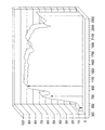
1つの塗料(例えば、黄色10P270)が3つの異なる色のLEDと共に使用される可能性が検討された。この場合、異なる入力波長からの異なる信号パターンを観察するため、塗料の反射のスペクトル特性を使用することができた。図5に示されるように、入力波長の範囲が予期された明白な又は異なる信号を提供する反射応答を確立するために利用され得るような、塗料の反射特性は入力LEDの波長に合致し得る様々な山と谷とを有する。例えば、反射の特徴に関して、400−470nmの入力波長は、予期される10%の反射の応答を提供する可能性があり、その一方で、690−700nm及び940−950nmの入力は、それぞれ予期される60%−90%の反射の応答を提供する。そこで、反応の明白な値及び又は割合は正規の符号信号を確立するために比較され得る。
(6th example-3 color illumination)
The possibility of using one paint (eg yellow 10P270) with three different colored LEDs was considered. In this case, the spectral characteristics of the paint reflection could be used to observe different signal patterns from different input wavelengths. As shown in FIG. 5, the reflective properties of the paint can match the wavelength of the input LED, such that the range of input wavelengths can be utilized to establish a reflective response that provides the expected obvious or different signal. It has various mountains and valleys. For example, with respect to reflection characteristics, an input wavelength of 400-470 nm may provide the expected 10% reflection response, while inputs of 690-700 nm and 940-950 nm are expected, respectively. Provides a 60% -90% reflection response. Thus, the apparent value and / or rate of response can be compared to establish a normal sign signal.
<実装例>
(3色LED)
より小型のパッケージにおいて、図5に関して記載されたような、より複雑な符号信号を生じさせるために、1つの3色LEDが使用され得る。例えば、3色(赤、緑、青)のLEDが、共通の光線経路に沿った異なる色の連続の及びパターン化された出力を提供するために構成され得る。そこで、その光は、個々の色の信号を受信するためのただ1つの受信機を要求する共通の基板に対して容易に向けられる。更に、正規の信号を代表するために統合され得る、追加の反射符号を生成するための、1つ以上の3色LEDが対応する受信機及び塗料と組み合わされ得る。
<Example of implementation>
(3-color LED)
In a smaller package, a single tri-color LED can be used to produce a more complex code signal as described with respect to FIG. For example, three color (red, green, blue) LEDs can be configured to provide continuous and patterned output of different colors along a common ray path. The light is then easily directed to a common substrate that requires only one receiver to receive the individual color signals. In addition, one or more tri-color LEDs can be combined with corresponding receivers and paints to generate additional reflection codes that can be integrated to represent a regular signal.
(見えないバーコード)
肉眼では実質的に同一の外観を有し、しかし、特定の照明の下では特定の反射応答を示す、バーコード型のシステムが塗料の組合せを用いて設計され得る。この場合、上記の通り、「符号」は専門的でない観察者には事実上目に見えないように、塗料は下部の基板/製品の色と実質的に合致するように選択され得る。
(Invisible barcode)
A barcode-type system can be designed with a combination of paints that has substantially the same appearance to the naked eye, but shows a specific reflection response under specific lighting. In this case, as described above, the paint may be selected to substantially match the color of the underlying substrate / product so that the “sign” is virtually invisible to non-professional observers.
この実装は、2つの黒色塗料(黒色30C591(「0」と称される)及び黒色20F944(「1」と称される))を用いて設計された、個々の塗料の3つの交互に変わる筋が基板上に塗られ、950nmのLEDで照らされた、バーコードにおいてテストされた。即ち、バーコードは「010101」のパターンを有していた。この符号はLED/センサの組合せに関連するバーコードの連続する入れ替わりによって読み取られた。この結果は、対応する「高い」電圧信号「x」及び「低い」電圧信号「y」、即ち、「xyxyxy」として反射パターンが識別できることを示している。 This implementation is designed with two black paints (black 30C591 (referred to as “0”) and black 20F944 (referred to as “1”)), three alternating streaks of individual paints. Were coated on the substrate and tested in barcodes illuminated with 950 nm LEDs. That is, the barcode has a pattern of “010101”. This code was read by successive permutations of the bar code associated with the LED / sensor combination. This result shows that the reflection pattern can be identified as the corresponding “high” voltage signal “x” and “low” voltage signal “y”, ie, “xyxyxy”.
バーコードに係る種々の実施形態において、関連する電子機器は、製品の組合せ及び/又は相対的な符号の複雑さの物理的な特徴に従って設計され得る。即ち、符号に関連するLED/センサの組合せの移動によって符号が読み取られる1つのLED/センサの組合せを利用して、又は、複数のLED/センサの組合せが上記の個々のバーコード要素(例えば、色又は縞)に適合されて、バーコードが実装され得る。 In various embodiments relating to barcodes, the associated electronics can be designed according to physical characteristics of product combinations and / or relative code complexity. That is, using a single LED / sensor combination where the code is read by movement of the LED / sensor combination associated with the code, or multiple LED / sensor combinations may include the individual bar code elements described above (eg, A barcode can be implemented, adapted to the color or stripe).
重要なことは、これらの性質に基づいて、LED、センサ、塗料、要素の物理的な適合及び動作、並びに、基板の塗料の大きさ及び形状、のパラメータの様々な組合せ、を利用する、広範囲の信号パターンが作り出され得ることが理解される。 Importantly, based on these properties, a wide range of LEDs, sensors, paints, physical adaptation and operation of elements, and various combinations of substrate paint size and shape parameters are utilized. It is understood that a number of signal patterns can be created.
関連する電子機器は特定の実施形態に、近接スイッチ及び/又はパルス信号を介して電力消費を最小化する或いは削減することを含む、様々な機能を提供するよう設計され得ることも理解される。種々の実施形態において、システムはまた、図3Aに示されるように、1つの光源が異なる光学コーティングに対して向けられることを可能とする、1つ又はそれ以上の光学要素61を含み得る。この場合、光学要素は送信機の光を、異なる光学コーティングに向けられた離れた光学経路に対して、分割するために用いられ得る。受信機に係る配列及び受信の特徴に応じて、両方の光学コーティングからの反射光を受信するために1つの受信機が利用される。
It is also understood that the associated electronics may be designed to provide various functions in certain embodiments, including minimizing or reducing power consumption via proximity switches and / or pulse signals. In various embodiments, the system may also include one or more
(製品の組合せの関係)
製品の組合せの間の物理的な関係は、実装される符号のタイプに寄与する。一般的に、利用可能な物理的な空間と1つの要素が他の要素に関連する分離及び/又は移動は符号化システムの特定の設計を決定し得る。近接スイッチ及びパルス上の電力等の特徴は、当業者によって理解されるように、電力消費を最小限にするために利用され得る。
(Product combination relationship)
The physical relationship between product combinations contributes to the type of code implemented. In general, the available physical space and the separation and / or movement of one element relative to another may determine the particular design of the encoding system. Features such as proximity switches and power on the pulse can be utilized to minimize power consumption, as will be appreciated by those skilled in the art.
(塗料)
本発明に従って、上記の通り、塗料の反射の特性を充分に引き出すために、多くの異なる塗料が利用され得る。当業者によって理解されるように、最終的な塗料の選択では、求められる符号化アプリケーションに基づいて、求められる安全性のレベル、基板の形状及び大きさ並びに基板の色等の要因を含み且つそれに限られないアプリケーションに関連する多数の要因が考慮される。
(paint)
In accordance with the present invention, as described above, many different paints can be utilized to fully exploit the reflective properties of the paint. As will be appreciated by those skilled in the art, the final paint selection includes and includes factors such as the required level of safety, board shape and size, and board color, based on the required coding application. A number of factors related to non-limiting applications are considered.
塗料は種々の周知の製品技術を使用した基板に適用される。 The paint is applied to the substrate using various well-known product technologies.
(LED)
適切なLEDの選択において使用される要因は、スペクトル発光特性、発光特性の空間的な寸法(例えば、角度寸法)及び発光色等を含み且つそれに限られない。
(LED)
Factors used in selecting an appropriate LED include, but are not limited to, spectral emission characteristics, spatial dimensions of the emission characteristics (eg, angular dimensions), emission color, and the like.
(フォトセンサ)
フォトセンサは、スペクトル感度(例えば、可視光及び近赤外線)、反応の空間的な寸法、大きさ(例えば、輪郭の大きさ及び寸法)及び速度を含み且つそれに限られない要因に基づいて選択され得る。フォトセンサはフォトダイオード、フォトトランジスタ及び光−電圧変換器を含み得る。
(Photo sensor)
Photosensors are selected based on factors including, but not limited to, spectral sensitivity (eg, visible and near infrared), spatial dimensions of response, magnitude (eg, contour size and dimensions) and speed. obtain. The photosensor can include a photodiode, a phototransistor, and a light-to-voltage converter.
本発明が、望ましい実施形態及び望ましいその使用に関連して説明され、そして、例示されているが、それに限定されるものではなく、当業者によって理解される、本発明の完全な、意図された範囲内で、修正及び変更がなされ得る。 While the invention has been described and illustrated in connection with preferred embodiments and preferred uses thereof, it is not intended to be limited thereto but to be understood by those of ordinary skill in the art Modifications and changes may be made within the scope.
Claims (22)
第1の光信号を光学コーティングに対して送出するため、前記光学コーティングに隣接して作動可能に位置している送信機、
前記光学コーティングからの反射光を受信するため、前記光学コーティングに隣接して作動可能に位置している受信機、並びに、
前記受信機側で正規の信号に対する反射光を解釈するため、及び、前記光学コーティングが正規の、又は、非正規の、いずれの光学コーティングであるかを判定するため、前記受信機に作動可能に接続された受信電子機器、
を含むシステム。 A system for distinguishing the spectral response of one or more optical coatings on a substrate between a transmitter and a receiver, comprising:
A transmitter operatively located adjacent to the optical coating for delivering a first optical signal to the optical coating;
A receiver operatively located adjacent to the optical coating for receiving reflected light from the optical coating; and
Operable to the receiver to interpret reflected light for a regular signal at the receiver side and to determine whether the optical coating is a regular or non-regular optical coating Connected receiving electronics,
Including system.
前記送信機はLED光源である、システム。 The system of claim 1, wherein
The system, wherein the transmitter is an LED light source.
前記システムは少なくとも2つの送信機を含み、且つ、
個々の送信機は異なる波長の光を前記光学コーティングに対して送出する、
システム。 A system according to claim 1 or claim 2, wherein
The system includes at least two transmitters; and
Individual transmitters emit different wavelengths of light to the optical coating;
system.
個々の送信機は共通の光学コーティングに対して光を送出し、且つ、
前記光学コーティングは個々の光の波長に対する異なる反射の特性を有する、
システム。 The system of claim 3, wherein
Individual transmitters emit light to a common optical coating; and
The optical coating has different reflection characteristics for individual wavelengths of light;
system.
前記正規の信号は、個々の送信機からの、受信信号の組合せである、システム。 The system according to claim 3 or claim 4,
The regular signal is a combination of received signals from individual transmitters.
前記光学コーティングは少なくとも2つの光学コーティングを含み、且つ、
個々の光学コーティングは付随する送信機と受信機の組合せと対になっている、
システム。 The system of claim 1, wherein
The optical coating comprises at least two optical coatings; and
Each optical coating is paired with an associated transmitter and receiver combination,
system.
個々の送信機と受信機との組合せに係る個々の送信機は異なる波長の光を発光する、システム。 The system of claim 6, wherein
A system in which individual transmitters associated with a combination of individual transmitters and receivers emit light of different wavelengths.
前記少なくとも2つの光学コーティングは異なる反射の特性を有する、システム。 The system according to claim 6 or 7,
The system, wherein the at least two optical coatings have different reflective properties.
個々の光学コーティングは異なる反射の特性を有する、システム。 The system of claim 7, wherein
Individual optical coatings have different reflective properties.
前記光学コーティングは、少なくとも2つの空間的に離れたな光学コーティング、及び、1つの送信機と受信機との組合せ、を含み、
前記送信機からの光は、光学システムを通って前記少なくとも2つの空間的に離れた光学コーティングへ向けられ、且つ、
個々の前記少なくとも2つの空間的に離れた光学コーティングからの反射光は、前記送信機と受信機との組合せの前記受信機にて受光される、
システム。 The system of claim 1, wherein
The optical coating comprises at least two spatially separated optical coatings, and one transmitter and receiver combination;
Light from the transmitter is directed through the optical system to the at least two spatially separated optical coatings; and
Reflected light from each of the at least two spatially separated optical coatings is received at the receiver of the transmitter and receiver combination;
system.
前記少なくとも2つの空間的に離れた光学コーティングは、異なる反射特性を有する、システム。 The system of claim 10, wherein
The system, wherein the at least two spatially separated optical coatings have different reflective properties.
前記基板は回転基板であり、且つ、
前記回転基板は前記基板上の前記送信機と受信機との組合せの反射点を回転させて通過する少なくとも1つの光学コーティングを含む、
システム。 The system of claim 1, wherein
The substrate is a rotating substrate; and
The rotating substrate includes at least one optical coating that rotates and passes through a reflection point of the transmitter and receiver combination on the substrate;
system.
前記基板は異なる反射の特性を有する少なくとも2つの光学コーティングを含む、システム。 The system of claim 12, wherein
The system wherein the substrate includes at least two optical coatings having different reflective properties.
前記少なくとも2つの光学コーティングは塗装された縞である、システム。 The system according to claim 12 or claim 13,
The system, wherein the at least two optical coatings are painted stripes.
前記少なくとも2つの光学コーティングは実質的に同一の色及び異なる反射の特性を有する、システム。 The system of claim 14, wherein
The system, wherein the at least two optical coatings have substantially the same color and different reflection characteristics.
前記LEDは、前記LED内にて少なくとも2つの波長の連続発生を可能とする多色LEDであり、且つ、
前記受信機は前記少なくとも2つの波長に対応する反射信号を受信する、
システム。 The system according to any one of claims 2 to 15,
The LED is a multi-color LED that allows continuous generation of at least two wavelengths within the LED, and
The receiver receives reflected signals corresponding to the at least two wavelengths;
system.
前記第1の光信号はパルス上である、システム。 The system according to any one of claims 1 to 16,
The system, wherein the first optical signal is on a pulse.
送信機と受信機とを含む少なくとも1つの送信機と受信機との組合せを含み、
前記送信機は、前記基板上の第1及び第2の光学コーティングに対して光信号を送出し、
前記システムは、前記第2の光学コーティングに対する光信号の一部をそらすため、前記送信機に隣接して位置している光学要素を含み、
前記受信機は、第1及び第2の光学コーティングからの反射光を受信するため、第1及び第2の光学コーティングに隣接して作動可能に位置する、
システム。 A system for distinguishing the spectral response of at least two optical coatings on a substrate, comprising:
Including at least one transmitter and receiver combination including a transmitter and a receiver;
The transmitter sends optical signals to the first and second optical coatings on the substrate;
The system includes an optical element positioned adjacent to the transmitter to divert a portion of the optical signal to the second optical coating;
The receiver is operatively positioned adjacent to the first and second optical coatings for receiving reflected light from the first and second optical coatings;
system.
(a)前記主要装置に対して作動可能な位置に前記基板の前記光学コーティングを設置するステップ、
(b)前記主要装置から前記光学コーティングに対して第1の光信号を送出するステップ、
(c)前記主要装置上で前記光学コーティングが反射させた反射光信号を受信するステップ、
(d)前記反射光信号を所定の信号パターンと比較し、且つ、前記反射光信号が前記所定の信号パターンと一致するか否かを判定するステップ、
(e)(d)の結果に基づいて反応信号を提供するステップ、
を含む方法。 A method for evaluating a substrate having an optical coating associated with a main device comprising:
(A) placing the optical coating on the substrate in a position operable with respect to the main device;
(B) sending a first optical signal from the main device to the optical coating;
(C) receiving a reflected light signal reflected by the optical coating on the main device;
(D) comparing the reflected light signal with a predetermined signal pattern and determining whether the reflected light signal matches the predetermined signal pattern;
(E) providing a reaction signal based on the result of (d);
Including methods.
前記(b)のステップは少なくとも第2の光信号を含む、方法。 The method of claim 19, wherein
The step (b) includes at least a second optical signal.
光学コーティングは少なくとも2つの光学コーティングであり、
個々の光学コーティングは、前記(a)乃至(c)のステップが、付随する送信機と受信機との組合せと対になって設置、送出及び受信が行われることを含むように、付随する送信機と受信機との組合せと対になる、
方法。 The method of claim 19, wherein
The optical coating is at least two optical coatings;
Each optical coating has an associated transmission such that the steps (a) to (c) include installation, transmission and reception paired with an associated transmitter and receiver combination. Paired with a combination of a receiver and a receiver,
Method.
個々の前記少なくとも2つの光学コーティングは異なる反射の特性を有する、方法。 The method of claim 21, wherein
The method wherein each said at least two optical coatings have different reflective properties.
Applications Claiming Priority (3)
| Application Number | Priority Date | Filing Date | Title |
|---|---|---|---|
| US38167110P | 2010-09-10 | 2010-09-10 | |
| US61/381,671 | 2010-09-10 | ||
| PCT/CA2011/001008 WO2012031354A1 (en) | 2010-09-10 | 2011-09-09 | Signal and detection system for keying applications |
Publications (2)
| Publication Number | Publication Date |
|---|---|
| JP2013542408A true JP2013542408A (en) | 2013-11-21 |
| JP2013542408A5 JP2013542408A5 (en) | 2015-12-10 |
Family
ID=45810037
Family Applications (1)
| Application Number | Title | Priority Date | Filing Date |
|---|---|---|---|
| JP2013527428A Pending JP2013542408A (en) | 2010-09-10 | 2011-09-09 | Signal and detection system for coding applications |
Country Status (12)
| Country | Link |
|---|---|
| US (2) | US9476826B2 (en) |
| EP (1) | EP2614360A4 (en) |
| JP (1) | JP2013542408A (en) |
| KR (1) | KR20140007064A (en) |
| CN (1) | CN103221804A (en) |
| AU (1) | AU2011301170B2 (en) |
| BR (1) | BR112013005279B1 (en) |
| CA (1) | CA2810701C (en) |
| MX (2) | MX336955B (en) |
| NZ (1) | NZ607905A (en) |
| RU (1) | RU2595296C2 (en) |
| WO (1) | WO2012031354A1 (en) |
Cited By (1)
| Publication number | Priority date | Publication date | Assignee | Title |
|---|---|---|---|---|
| JP2018519870A (en) * | 2015-05-07 | 2018-07-26 | 1928732 オンタリオ インコーポレイテッド | Signal detection system for pairing products |
Families Citing this family (6)
| Publication number | Priority date | Publication date | Assignee | Title |
|---|---|---|---|---|
| US10893781B2 (en) * | 2011-05-27 | 2021-01-19 | Sun Chemical Corporation | Authentication reader and a dispenser comprising the authentication reader |
| GB201118109D0 (en) * | 2011-10-20 | 2011-11-30 | Reckitt Benckiser Llc | A dispenser for dispensing a product |
| US9999323B2 (en) | 2011-05-27 | 2018-06-19 | Sun Chemical Corporation | Authentication reader and a dispenser comprising the authentication reader |
| MX351575B (en) | 2011-12-20 | 2017-10-18 | Smart Wave Tech Corp | Systems and methods for authenticating bulk products. |
| US20150355099A1 (en) * | 2014-06-06 | 2015-12-10 | Hamilton Sundstrand Corporation | Scratch verification apparatus and method |
| DE102016111348A1 (en) * | 2016-06-21 | 2017-12-21 | Bundesdruckerei Gmbh | DOCUMENTS READER |
Citations (5)
| Publication number | Priority date | Publication date | Assignee | Title |
|---|---|---|---|---|
| JPH05506117A (en) * | 1990-03-29 | 1993-09-02 | ジェニイ サプライズ エンタープライズ,インク. | ALU status determination device |
| JPH11342662A (en) * | 1998-05-29 | 1999-12-14 | Toshiba Tec Corp | Method and system for judging object of information apparatus |
| JP2003521050A (en) * | 2000-01-21 | 2003-07-08 | フレックス プロダクツ インコーポレイテッド | Automatic object verification system and method using optical interference device |
| JP2003260804A (en) * | 2002-03-08 | 2003-09-16 | Canon Inc | Ink tank and ink tank inspecting device |
| JP2005022292A (en) * | 2003-07-03 | 2005-01-27 | Nippon Oil Corp | Identifying structure of object and object provided therewith |
Family Cites Families (45)
| Publication number | Priority date | Publication date | Assignee | Title |
|---|---|---|---|---|
| US4204765A (en) * | 1977-12-07 | 1980-05-27 | Ardac, Inc. | Apparatus for testing colored securities |
| CH659433A5 (en) * | 1982-10-04 | 1987-01-30 | Landis & Gyr Ag | DOCUMENT WITH A REFLECTIVE OPTICAL SECURITY ELEMENT. |
| US5114226A (en) * | 1987-03-20 | 1992-05-19 | Digital Optronics Corporation | 3-Dimensional vision system utilizing coherent optical detection |
| IL94782A0 (en) * | 1989-06-19 | 1991-04-15 | Lansco Inc | Authentication apparatus using resonance absorption of light |
| US5093147A (en) | 1990-09-12 | 1992-03-03 | Battelle Memorial Institute | Providing intelligible markings |
| US5260582A (en) * | 1992-04-20 | 1993-11-09 | Danek Robert J | Currency verification device for detecting the presence or the absence of security threads |
| US5856048A (en) * | 1992-07-27 | 1999-01-05 | Dai Nippon Printing Co., Ltd. | Information-recorded media and methods for reading the information |
| EP0700980B1 (en) | 1994-03-17 | 1999-11-17 | Hitachi Maxell, Ltd. | PHOSPHOR, PHOSPHOR COMPOSITION and FLUORESCENT MARK CARRIER |
| US5862844A (en) | 1996-05-03 | 1999-01-26 | Nartron Corporation | Methods and systems for controlling a dispensing apparatus |
| US5836482A (en) * | 1997-04-04 | 1998-11-17 | Ophardt; Hermann | Automated fluid dispenser |
| GB2325883B (en) * | 1997-06-03 | 2000-01-12 | Portals Ltd | A security article,a method and manufacture of the security article,a method of verifying authenticity of the security article and security paper |
| US6045894A (en) * | 1998-01-13 | 2000-04-04 | 3M Innovative Properties Company | Clear to colored security film |
| DE19836813A1 (en) | 1998-08-14 | 2000-02-24 | Bundesdruckerei Gmbh | Value and security document with optically stimulable dyes for authenticity testing |
| US7566142B2 (en) * | 2004-02-13 | 2009-07-28 | Jam Strait, Inc. | Changing color LEDS |
| US6407376B1 (en) * | 2000-03-03 | 2002-06-18 | Axsun Technologies, Inc. | Optical channel monitoring system with self-calibration |
| EP1354919B1 (en) | 2000-11-16 | 2008-08-13 | Fujitsu Limited | Latent image-use printing ink composition, printed matter containing latent image recorded by the ink composition, reading method by latent image information and latent image information reading device |
| US6793723B2 (en) | 2001-05-10 | 2004-09-21 | Pitney Bowes Inc. | Homogeneous photosensitive optically variable ink compositions for ink jet printing |
| US20030042438A1 (en) * | 2001-08-31 | 2003-03-06 | Lawandy Nabil M. | Methods and apparatus for sensing degree of soiling of currency, and the presence of foreign material |
| US6837605B2 (en) * | 2001-11-28 | 2005-01-04 | Osram Opto Semiconductors Gmbh | Led illumination system |
| US7487109B2 (en) * | 2002-01-03 | 2009-02-03 | International Business Machines Corporation | Method and apparatus for optimizing a security database for a self-service checkout system |
| DE10233928A1 (en) * | 2002-07-25 | 2004-02-12 | Giesecke & Devrient Gmbh | Method and device for checking the authenticity of a security element |
| US7097074B2 (en) | 2003-01-24 | 2006-08-29 | Kraft Foods R&D, Inc. | Machine for the preparation of beverages |
| US7040566B1 (en) | 2003-04-08 | 2006-05-09 | Alwin Manufacturing Co., Inc. | Dispenser with material-recognition apparatus and material-recognition method |
| US20060180792A1 (en) | 2003-06-26 | 2006-08-17 | Prime Technology Llc | Security marker having overt and covert security features |
| US7028861B2 (en) * | 2003-12-16 | 2006-04-18 | Joseph S. Kanfer | Electronically keyed dispensing systems and related methods of installation and use |
| US7726599B2 (en) * | 2003-12-31 | 2010-06-01 | Kimberly-Clark Worldwide, Inc. | Apparatus and method for dispensing sheet material |
| EP1756649B1 (en) | 2004-05-20 | 2018-11-28 | VerifyMe, Inc. | Illumination sources and subjects having distinctly matched and mismatched narrow spectral bands |
| US7192474B2 (en) | 2004-06-22 | 2007-03-20 | Pitney Bowes Inc. | IR absorbing photosensitive optically variable ink compositions and process |
| EP1619465A1 (en) * | 2004-07-19 | 2006-01-25 | Nederlandse Organisatie Voor Toegepast-Natuurwetenschappelijk Onderzoek Tno | Optical monitoring apparatus and method of monitoring optical coatings |
| US7080755B2 (en) * | 2004-09-13 | 2006-07-25 | Michael Handfield | Smart tray for dispensing medicaments |
| US8927892B2 (en) | 2004-10-22 | 2015-01-06 | Parallel Synthesis Technologies | Rare earth downconverting phosphor compositions for optically encoding objects and methods and apparatus relating to same |
| US20060092210A1 (en) * | 2004-10-29 | 2006-05-04 | Selvan Maniam | Color sensor counterfeit ink detection |
| US7621426B2 (en) | 2004-12-15 | 2009-11-24 | Joseph Kanfer | Electronically keyed dispensing systems and related methods utilizing near field frequency response |
| AU2006202315B2 (en) * | 2005-06-17 | 2011-01-27 | Viavi Solutions Inc. | Covert security coating |
| DE102005033598A1 (en) * | 2005-07-19 | 2007-01-25 | Giesecke & Devrient Gmbh | Value document, production and testing of value documents |
| US20080087189A1 (en) | 2005-10-03 | 2008-04-17 | Sun Chemical Corporation | Security pigments and the process of making thereof |
| EP1943188A2 (en) | 2005-10-03 | 2008-07-16 | Sun Chemical Corporation | Security pigments and the process of making thereof |
| US8689677B2 (en) | 2005-12-12 | 2014-04-08 | Carrier Corporation | Data input system in postmix dispenser |
| US7674326B2 (en) | 2006-10-12 | 2010-03-09 | Xerox Corporation | Fluorescent phase change inks |
| ZA200903647B (en) * | 2006-11-28 | 2010-08-25 | Innovative American Technology | Multi-stage system for verification of container contents |
| US8071933B2 (en) | 2007-06-18 | 2011-12-06 | Gotohti.Com Inc | Photochromic optically keyed dispenser |
| CN101883514A (en) * | 2007-12-21 | 2010-11-10 | 佐治亚-太平洋消费产品有限合伙公司 | The method of product, distributor and allocated product |
| RU2378625C2 (en) * | 2008-03-03 | 2010-01-10 | Федеральное государственное учреждение "24 Центральный научно-исследовательский институт Министерства обороны Российской Федерации" | Method of measurement of brightness characteristics of objects in optical band of spectrum and device for its implementation |
| US20090276091A1 (en) | 2008-04-30 | 2009-11-05 | Emeric John Duha | Apparatus for use in dispensing tinted paint |
| US8240508B2 (en) * | 2008-12-29 | 2012-08-14 | Gojo Industries, Inc. | Low cost radio frequency identification (RFID) dispensing systems |
-
2011
- 2011-09-09 CN CN2011800435243A patent/CN103221804A/en active Pending
- 2011-09-09 MX MX2015002596A patent/MX336955B/en unknown
- 2011-09-09 WO PCT/CA2011/001008 patent/WO2012031354A1/en active Application Filing
- 2011-09-09 CA CA2810701A patent/CA2810701C/en active Active
- 2011-09-09 KR KR1020137006449A patent/KR20140007064A/en not_active Application Discontinuation
- 2011-09-09 JP JP2013527428A patent/JP2013542408A/en active Pending
- 2011-09-09 EP EP11822955.8A patent/EP2614360A4/en not_active Ceased
- 2011-09-09 AU AU2011301170A patent/AU2011301170B2/en active Active
- 2011-09-09 BR BR112013005279-1A patent/BR112013005279B1/en active IP Right Grant
- 2011-09-09 MX MX2013002705A patent/MX2013002705A/en active IP Right Grant
- 2011-09-09 RU RU2013115834/28A patent/RU2595296C2/en active
- 2011-09-09 NZ NZ607905A patent/NZ607905A/en unknown
-
2013
- 2013-03-08 US US13/791,073 patent/US9476826B2/en active Active
-
2016
- 2016-09-12 US US15/263,026 patent/US20160377550A1/en not_active Abandoned
Patent Citations (5)
| Publication number | Priority date | Publication date | Assignee | Title |
|---|---|---|---|---|
| JPH05506117A (en) * | 1990-03-29 | 1993-09-02 | ジェニイ サプライズ エンタープライズ,インク. | ALU status determination device |
| JPH11342662A (en) * | 1998-05-29 | 1999-12-14 | Toshiba Tec Corp | Method and system for judging object of information apparatus |
| JP2003521050A (en) * | 2000-01-21 | 2003-07-08 | フレックス プロダクツ インコーポレイテッド | Automatic object verification system and method using optical interference device |
| JP2003260804A (en) * | 2002-03-08 | 2003-09-16 | Canon Inc | Ink tank and ink tank inspecting device |
| JP2005022292A (en) * | 2003-07-03 | 2005-01-27 | Nippon Oil Corp | Identifying structure of object and object provided therewith |
Cited By (3)
| Publication number | Priority date | Publication date | Assignee | Title |
|---|---|---|---|---|
| JP2018519870A (en) * | 2015-05-07 | 2018-07-26 | 1928732 オンタリオ インコーポレイテッド | Signal detection system for pairing products |
| US11026539B2 (en) | 2015-05-07 | 2021-06-08 | Smart Wave Technologies, Inc. | Signal and detection system for pairing products |
| US11889945B2 (en) | 2015-05-07 | 2024-02-06 | Smart Wave Technologies, Inc. | Signal and detection system for pairing products |
Also Published As
| Publication number | Publication date |
|---|---|
| BR112013005279B1 (en) | 2020-03-31 |
| CA2810701A1 (en) | 2012-03-15 |
| US20130188187A1 (en) | 2013-07-25 |
| RU2595296C2 (en) | 2016-08-27 |
| CA2810701C (en) | 2017-06-20 |
| NZ607905A (en) | 2014-10-31 |
| RU2013115834A (en) | 2014-10-20 |
| AU2011301170A1 (en) | 2013-03-28 |
| EP2614360A4 (en) | 2015-04-22 |
| AU2011301170A8 (en) | 2013-05-23 |
| MX2013002705A (en) | 2013-07-22 |
| KR20140007064A (en) | 2014-01-16 |
| EP2614360A1 (en) | 2013-07-17 |
| US9476826B2 (en) | 2016-10-25 |
| MX336955B (en) | 2016-02-08 |
| CN103221804A (en) | 2013-07-24 |
| BR112013005279A2 (en) | 2017-06-06 |
| WO2012031354A1 (en) | 2012-03-15 |
| AU2011301170B2 (en) | 2014-09-04 |
| US20160377550A1 (en) | 2016-12-29 |
Similar Documents
| Publication | Publication Date | Title |
|---|---|---|
| US11889945B2 (en) | Signal and detection system for pairing products | |
| US9476826B2 (en) | Signal and detection system for keying applications | |
| CN201837586U (en) | Device for verifying article by using label agent material | |
| CA2517041C (en) | Fluorescent ink detector | |
| US20120104278A1 (en) | System And Method For The Excitation, Interrogation, And Identification Of Covert Taggants | |
| US8042741B2 (en) | Synthetic barcode system and method | |
| US11853843B2 (en) | Authentication system | |
| WO2010012046A1 (en) | A code carrier and an apparatus for reading a code carrier | |
| US9999323B2 (en) | Authentication reader and a dispenser comprising the authentication reader | |
| US10893781B2 (en) | Authentication reader and a dispenser comprising the authentication reader | |
| CA2224731A1 (en) | Anticounterfeiting method | |
| US20170132440A1 (en) | Optical reader device, tag for use on a disposable or replaceable component, optical data validation system and method for optical data validation | |
| US11278161B2 (en) | Authentication reader and a dispenser comprising the authentication reader | |
| RU2225030C2 (en) | Method and device for verifying genuineness of marking | |
| KR20210030752A (en) | Detector to recognize code and detecting method using the same |
Legal Events
| Date | Code | Title | Description |
|---|---|---|---|
| A621 | Written request for application examination |
Free format text: JAPANESE INTERMEDIATE CODE: A621 Effective date: 20140717 |
|
| A131 | Notification of reasons for refusal |
Free format text: JAPANESE INTERMEDIATE CODE: A131 Effective date: 20150721 |
|
| A711 | Notification of change in applicant |
Free format text: JAPANESE INTERMEDIATE CODE: A712 Effective date: 20150917 |
|
| A521 | Request for written amendment filed |
Free format text: JAPANESE INTERMEDIATE CODE: A523 Effective date: 20150924 |
|
| A521 | Request for written amendment filed |
Free format text: JAPANESE INTERMEDIATE CODE: A523 Effective date: 20151020 |
|
| A524 | Written submission of copy of amendment under article 19 pct |
Free format text: JAPANESE INTERMEDIATE CODE: A524 Effective date: 20151020 |
|
| A131 | Notification of reasons for refusal |
Free format text: JAPANESE INTERMEDIATE CODE: A131 Effective date: 20160405 |
|
| A02 | Decision of refusal |
Free format text: JAPANESE INTERMEDIATE CODE: A02 Effective date: 20161108 |