JP2013525843A - Method for optimizing both noise reduction and speech quality in a system with single or multiple microphones - Google Patents
Method for optimizing both noise reduction and speech quality in a system with single or multiple microphones Download PDFInfo
- Publication number
- JP2013525843A JP2013525843A JP2013506188A JP2013506188A JP2013525843A JP 2013525843 A JP2013525843 A JP 2013525843A JP 2013506188 A JP2013506188 A JP 2013506188A JP 2013506188 A JP2013506188 A JP 2013506188A JP 2013525843 A JP2013525843 A JP 2013525843A
- Authority
- JP
- Japan
- Prior art keywords
- noise
- signal
- value
- subband
- subband signal
- Prior art date
- Legal status (The legal status is an assumption and is not a legal conclusion. Google has not performed a legal analysis and makes no representation as to the accuracy of the status listed.)
- Pending
Links
- 230000009467 reduction Effects 0.000 title claims abstract description 89
- 238000000034 method Methods 0.000 title claims abstract description 57
- 201000007201 aphasia Diseases 0.000 claims abstract description 25
- 230000003595 spectral effect Effects 0.000 claims description 5
- 230000003044 adaptive effect Effects 0.000 abstract description 9
- 238000005516 engineering process Methods 0.000 abstract description 8
- 230000001629 suppression Effects 0.000 description 58
- 238000012545 processing Methods 0.000 description 21
- 238000001228 spectrum Methods 0.000 description 17
- 230000008569 process Effects 0.000 description 11
- 238000010586 diagram Methods 0.000 description 10
- 230000006870 function Effects 0.000 description 7
- 230000015556 catabolic process Effects 0.000 description 6
- 238000006731 degradation reaction Methods 0.000 description 6
- 238000009499 grossing Methods 0.000 description 6
- 230000005236 sound signal Effects 0.000 description 5
- 238000004891 communication Methods 0.000 description 4
- 230000000694 effects Effects 0.000 description 4
- 238000009826 distribution Methods 0.000 description 3
- 238000012986 modification Methods 0.000 description 3
- 230000004048 modification Effects 0.000 description 3
- 230000002238 attenuated effect Effects 0.000 description 2
- 230000006399 behavior Effects 0.000 description 2
- 230000008901 benefit Effects 0.000 description 2
- 230000005540 biological transmission Effects 0.000 description 2
- 230000008859 change Effects 0.000 description 2
- 210000003477 cochlea Anatomy 0.000 description 2
- 230000001419 dependent effect Effects 0.000 description 2
- 238000013461 design Methods 0.000 description 2
- 238000002592 echocardiography Methods 0.000 description 2
- 238000011156 evaluation Methods 0.000 description 2
- 238000001914 filtration Methods 0.000 description 2
- 230000007774 longterm Effects 0.000 description 2
- 239000000203 mixture Substances 0.000 description 2
- 230000008447 perception Effects 0.000 description 2
- 238000012805 post-processing Methods 0.000 description 2
- 230000009286 beneficial effect Effects 0.000 description 1
- 230000015572 biosynthetic process Effects 0.000 description 1
- 238000006243 chemical reaction Methods 0.000 description 1
- 239000002131 composite material Substances 0.000 description 1
- 230000007423 decrease Effects 0.000 description 1
- 230000001934 delay Effects 0.000 description 1
- 238000001514 detection method Methods 0.000 description 1
- 238000004880 explosion Methods 0.000 description 1
- 238000000605 extraction Methods 0.000 description 1
- 238000007667 floating Methods 0.000 description 1
- 230000000873 masking effect Effects 0.000 description 1
- 239000003607 modifier Substances 0.000 description 1
- 238000001303 quality assessment method Methods 0.000 description 1
- 238000003786 synthesis reaction Methods 0.000 description 1
- 230000002123 temporal effect Effects 0.000 description 1
- 238000012360 testing method Methods 0.000 description 1
- 230000002087 whitening effect Effects 0.000 description 1
Images


Classifications
-
- G—PHYSICS
- G10—MUSICAL INSTRUMENTS; ACOUSTICS
- G10L—SPEECH ANALYSIS TECHNIQUES OR SPEECH SYNTHESIS; SPEECH RECOGNITION; SPEECH OR VOICE PROCESSING TECHNIQUES; SPEECH OR AUDIO CODING OR DECODING
- G10L21/00—Speech or voice signal processing techniques to produce another audible or non-audible signal, e.g. visual or tactile, in order to modify its quality or its intelligibility
- G10L21/02—Speech enhancement, e.g. noise reduction or echo cancellation
- G10L21/0208—Noise filtering
- G10L21/0216—Noise filtering characterised by the method used for estimating noise
- G10L21/0232—Processing in the frequency domain
-
- G—PHYSICS
- G10—MUSICAL INSTRUMENTS; ACOUSTICS
- G10L—SPEECH ANALYSIS TECHNIQUES OR SPEECH SYNTHESIS; SPEECH RECOGNITION; SPEECH OR VOICE PROCESSING TECHNIQUES; SPEECH OR AUDIO CODING OR DECODING
- G10L25/00—Speech or voice analysis techniques not restricted to a single one of groups G10L15/00 - G10L21/00
- G10L25/03—Speech or voice analysis techniques not restricted to a single one of groups G10L15/00 - G10L21/00 characterised by the type of extracted parameters
- G10L25/18—Speech or voice analysis techniques not restricted to a single one of groups G10L15/00 - G10L21/00 characterised by the type of extracted parameters the extracted parameters being spectral information of each sub-band
-
- H—ELECTRICITY
- H04—ELECTRIC COMMUNICATION TECHNIQUE
- H04R—LOUDSPEAKERS, MICROPHONES, GRAMOPHONE PICK-UPS OR LIKE ACOUSTIC ELECTROMECHANICAL TRANSDUCERS; DEAF-AID SETS; PUBLIC ADDRESS SYSTEMS
- H04R3/00—Circuits for transducers, loudspeakers or microphones
- H04R3/002—Damping circuit arrangements for transducers, e.g. motional feedback circuits
-
- G—PHYSICS
- G10—MUSICAL INSTRUMENTS; ACOUSTICS
- G10L—SPEECH ANALYSIS TECHNIQUES OR SPEECH SYNTHESIS; SPEECH RECOGNITION; SPEECH OR VOICE PROCESSING TECHNIQUES; SPEECH OR AUDIO CODING OR DECODING
- G10L21/00—Speech or voice signal processing techniques to produce another audible or non-audible signal, e.g. visual or tactile, in order to modify its quality or its intelligibility
- G10L21/02—Speech enhancement, e.g. noise reduction or echo cancellation
- G10L21/0208—Noise filtering
- G10L2021/02087—Noise filtering the noise being separate speech, e.g. cocktail party
Landscapes
- Engineering & Computer Science (AREA)
- Physics & Mathematics (AREA)
- Acoustics & Sound (AREA)
- Signal Processing (AREA)
- Human Computer Interaction (AREA)
- Audiology, Speech & Language Pathology (AREA)
- Health & Medical Sciences (AREA)
- Computational Linguistics (AREA)
- Multimedia (AREA)
- Quality & Reliability (AREA)
- Spectroscopy & Molecular Physics (AREA)
- Circuit For Audible Band Transducer (AREA)
- Soundproofing, Sound Blocking, And Sound Damping (AREA)
Abstract
【解決手段】本技術は、音声の損失歪みと雑音低減との間のトレードオフのバランスをとるために、洗練された制御レベルを用いる、音響信号の適応型の雑音低減方法を提供する。音響信号のサブバンド信号における雑音成分のエネルギーレベルは、サブバンド信号について推定された信号対雑音比と、サブバンド信号の音声歪みについて推測された閾値レベルとに基づいて、低減される。いくつかの実施形態において、サブバンド信号における雑音成分のエネルギーレベルは、少なくとも、残留雑音目標レベルまで低減され得る。かかる目標レベルとは、雑音成分が知覚されなくなるレベルとして定義され得る。The present technology provides an adaptive noise reduction method for acoustic signals that uses sophisticated control levels to balance the trade-off between speech loss distortion and noise reduction. The energy level of the noise component in the subband signal of the acoustic signal is reduced based on the signal to noise ratio estimated for the subband signal and the threshold level estimated for the audio distortion of the subband signal. In some embodiments, the energy level of the noise component in the subband signal can be reduced to at least a residual noise target level. Such a target level can be defined as a level at which no noise component is perceived.
Description
本発明は、音声処理に関し、特に、音声信号の適応型の雑音低減に関する。 The present invention relates to audio processing, and more particularly to adaptive noise reduction of audio signals.
現在、都合の悪い音声環境において、音響信号内の背景雑音を低減するための、数多くの方法が存在する。かかる一つの方法は、定常雑音抑制システム(stationary noise suppression system)を用いることである。定常雑音抑制システムは、入力雑音より小さい、固定量の出力雑音を常に提供する。一般的に、この雑音抑制は、12−13デシベル(dB)の範囲である。この雑音抑制は、音声の損失歪み(speech loss distortion)の生成を回避するために、控えめなレベルに固定される。そのような歪みは、より大きな雑音抑制を用いることで、より顕著となる。 Currently, there are a number of ways to reduce background noise in an acoustic signal in an unfavorable voice environment. One such method is to use a stationary noise suppression system. A stationary noise suppression system always provides a fixed amount of output noise that is less than the input noise. Generally, this noise suppression is in the range of 12-13 decibels (dB). This noise suppression is fixed at a conservative level to avoid generating speech loss distortion. Such distortion becomes more pronounced with greater noise suppression.
より大きな雑音抑制を提供するために、信号対雑音比(SNR)に基づいた、動的な雑音抑制システムが利用されてきた。かかるSNRは、抑制値(suppression value)を決定するために、用いることができる。不幸なことに、SNRそのものは、音声歪みの良い予測手段ではない。これは、音声環境の種々の雑音の存在に起因する。SNRは、音声が、雑音より、どれだけ大きいかを示す比率である。しかしながら、音声は、非定常的な信号であり、絶えず変動し、また、無音(pause)を含み得る。一般的には、ある期間にわたる音声エネルギーは、単語、無音、単語、無音等を含み得る。さらに、音声環境において定常雑音及び動的雑音が、表れる可能性がある。SNRは、かかる定常的又は非定常的な音声及び雑音の全てを平均化し、雑音の全体的なレベルがどの程度かに基づいて、比率を決定する。雑音信号の統計に関する考慮はなされていない。 In order to provide greater noise suppression, dynamic noise suppression systems based on signal-to-noise ratio (SNR) have been utilized. Such SNR can be used to determine a suppression value. Unfortunately, SNR itself is not a good predictor of speech distortion. This is due to the presence of various noises in the voice environment. The SNR is a ratio indicating how much speech is larger than noise. However, speech is a non-stationary signal that constantly fluctuates and can include pause. In general, audio energy over a period of time may include words, silence, words, silence, and the like. Furthermore, stationary noise and dynamic noise may appear in the voice environment. SNR averages all such stationary or non-stationary speech and noise and determines the ratio based on what the overall level of noise is. No consideration is given to noise signal statistics.
いくつかの先行技術のシステムにおいて、雑音スペクトルの推定に基づいて、強調フィルタ(enhancement filter)が生成され得る。ある一般的な強調フィルタは、ウィーナーフィルタである。 In some prior art systems, an enhancement filter may be generated based on an estimate of the noise spectrum. One common enhancement filter is a Wiener filter.
都合の悪いことに、強調フィルタは、一般的に、ユーザの知覚を考慮せずに、特定の数学的な誤差量を最小化するように構成されている。その結果、雑音を抑制する信号強調の副作用として、一定量の音声劣化(speech degradation)が生ずる。例えば、エネルギーが雑音より低い音声成分は、一般的に、強調フィルタにより、抑制されてしまう。これにより、音声スペクトルの出力の変更がもたらされ、音声歪みとして知覚される。雑音レベルが上昇すると、かかる音声劣化は、より厳しくなり、より多くの音声成分が、拡張フィルタによって、減衰する。すなわち、SNRが低下すると、より多くの音声成分が、雑音に埋もれるか、又は雑音として解釈され、より多くの音声の損失歪みをもたらす。このことは、より多くの音声の損失歪みと、音声劣化をもたらす。 Unfortunately, enhancement filters are typically configured to minimize certain mathematical error quantities without considering user perception. As a result, a certain amount of speech degradation occurs as a side effect of signal enhancement that suppresses noise. For example, a speech component whose energy is lower than noise is generally suppressed by an enhancement filter. This results in a change in the output of the audio spectrum and is perceived as audio distortion. As the noise level increases, such speech degradation becomes more severe, and more speech components are attenuated by the expansion filter. That is, as the SNR decreases, more speech components are buried in or interpreted as noise, resulting in more speech loss distortion. This results in more voice loss distortion and voice degradation.
従って、音声の損失歪みと、残留雑音との間のトレードオフのバランスをとる、適応型の雑音低減方法が提供されることが望まれる。 Accordingly, it would be desirable to provide an adaptive noise reduction method that balances the trade-off between speech loss distortion and residual noise.
本技術は、音声の損失歪みと雑音低減との間のトレードオフのバランスをとるために、洗練された制御レベルを用いる、音響信号の適応型の雑音低減方法を提供する。音響信号のサブバンド信号における雑音成分のエネルギーレベルは、サブバンド信号について推定された信号対雑音比と、サブバンド信号の音声歪みについて推測された閾値レベルとに基づいて、低減される。いくつかの実施形態において、サブバンド信号における雑音成分のエネルギーレベルは、少なくとも、残留雑音目標レベルまで低減され得る。かかる目標レベルとは、雑音成分が知覚されなくなるレベルとして定義され得る。 The present technology provides an adaptive noise reduction method for acoustic signals that uses sophisticated control levels to balance the trade-off between speech loss distortion and noise reduction. The energy level of the noise component in the subband signal of the acoustic signal is reduced based on the signal to noise ratio estimated for the subband signal and the threshold level estimated for the audio distortion of the subband signal. In some embodiments, the energy level of the noise component in the subband signal can be reduced to at least a residual noise target level. Such a target level can be defined as a level at which no noise component is perceived.
本明細書で説明される、音響信号の雑音を低減する方法は、音響信号を受信する段階と、前記音響信号を、複数のサブバンド信号へと分離する段階とを含む。次に、低減値(reduction value)が、前記複数のサブバンド信号のうちの一のサブバンド信号に適用され、前記サブバンド信号の雑音成分のエネルギーレベルを低減させる。前記低減値は、前記サブバンド信号の推定された信号対雑音比と、前記サブバンド信号における音声損失歪みの推定された閾値レベルとに基づく。 A method for reducing noise in an acoustic signal described herein includes receiving an acoustic signal and separating the acoustic signal into a plurality of subband signals. Next, a reduction value is applied to one subband signal of the plurality of subband signals to reduce an energy level of a noise component of the subband signal. The reduction value is based on an estimated signal to noise ratio of the subband signal and an estimated threshold level of speech loss distortion in the subband signal.
本明細書で説明される、音響信号内の雑音を低減するシステムは、メモリに保管され、かつプロセッサによって実行される、周波数分析モジュールを含み、前記周波数モジュールは、音響信号を受信し、前記音響信号を、複数のサブバンド信号へと分離する。本システムは、さらに、メモリに保管され、かつプロセッサによって実行される、雑音低減モジュールを含み、前記雑音低減モジュールは、低減値(reduction value)を、前記複数のサブバンド信号のうちの一のサブバンド信号に適用し、前記サブバンド信号の雑音成分のエネルギーレベルを低減させる。前記低減値は、前記サブバンド信号の推定された信号対雑音比と、前記サブバンド信号における音声の損失歪みの推定された閾値レベルとに基づく。 A system for reducing noise in an acoustic signal as described herein includes a frequency analysis module stored in memory and executed by a processor, the frequency module receiving an acoustic signal and the acoustic signal. The signal is separated into a plurality of subband signals. The system further includes a noise reduction module stored in memory and executed by the processor, wherein the noise reduction module assigns a reduction value to one subband signal of the plurality of subband signals. Applied to a band signal, the energy level of the noise component of the subband signal is reduced. The reduction value is based on an estimated signal-to-noise ratio of the subband signal and an estimated threshold level of speech loss distortion in the subband signal.
本明細書で説明される、コンピュータ読取可能な記憶媒体は、コンピュータに、音響信号を受信する段階と、前記音響信号を、複数のサブバンド信号へと分離する段階とを実行させるプログラムを具体化する。 The computer-readable storage medium described herein embodies a program that causes a computer to receive an acoustic signal and to separate the acoustic signal into a plurality of subband signals. To do.
本発明の、他の実施形態と利点は、以下の図面、詳細な説明及びクレームを検討することによって、理解することができる。 Other embodiments and advantages of the invention can be understood by studying the following drawings, detailed description, and claims.
本技術は、音声の損失歪みと雑音低減との間のトレードオフのバランスをとるために、洗練された制御レベルを用いる、音響信号の適応型の雑音低減方法を提供する。雑音低減(Noise reduction)は、低減値(reduction value)(例えば、減算値(subtraction value)及び/又はゲインマスクの乗算)を、音響信号の対応するサブバンド信号に適用し、同時に、雑音低減によってもたらされる音声損失歪みを、許容可能な閾値レベルに制限することによって、なされ得る。低減値及び実行される雑音低減は、サブバンド信号にわたって、変動し得る。雑音低減は、個々のサブバンド信号の特性と、雑音低減によってもたらされた、知覚された音声損失歪みによる特性に基づき得る。雑音低減は、音声信号における雑音低減と音声の品質とを、共に最適化するように、実行され得る。 The present technology provides an adaptive noise reduction method for acoustic signals that uses sophisticated control levels to balance the trade-off between speech loss distortion and noise reduction. Noise reduction applies a reduction value (eg, multiplication of a subtraction value and / or gain mask) to the corresponding subband signal of the acoustic signal, while simultaneously reducing noise. This can be done by limiting the resulting audio loss distortion to an acceptable threshold level. The reduction value and noise reduction performed can vary across the subband signals. Noise reduction may be based on the characteristics of the individual subband signals and the perceived speech loss distortion caused by the noise reduction. Noise reduction may be performed to optimize both noise reduction and speech quality in the speech signal.
本技術は、サブバンド信号において実行される雑音低減量の下限(すなわち、下限の閾値)を提供する。雑音低減の下限は、サブバンド信号の音声損失歪みの量を制限する働きをする。結果として、あるサブバンド信号において、可能であれば、大きな量の雑音低減がなされ得る。大きな量の雑音低減に対する、高い音声損失歪みが許容されないような場合には、雑音低減は、より小さくなり得る。 The present technique provides a lower limit (ie, a lower threshold) for the amount of noise reduction performed on the subband signal. The lower limit of noise reduction serves to limit the amount of audio loss distortion of the subband signal. As a result, a large amount of noise reduction can be achieved, if possible, in certain subband signals. If high speech loss distortion is not acceptable for a large amount of noise reduction, the noise reduction can be smaller.
本システムにより実行される雑音低減は、雑音抑制(noise suppression)及び/又は雑音消去(noise cancellation)の方法をとり得る。本システムは、主たる音響サブバンド信号に適用される、低減値を生成し、雑音低減を達成する。低減値は、サブバンド信号に乗算されるゲインマスクとして実装され、サブバンド信号における雑音成分のエネルギーレベルを抑制する。乗法による処理は、乗法性(multiplicative)雑音抑制と呼ばれる。雑音消去において、低減値は、混合(mixture)サブバンド信号から、雑音参照(noise reference)サブバンド信号を減算することにより、サブバンド信号において実行された雑音消去量の下限として生成され得る。 The noise reduction performed by the system may take the form of noise suppression and / or noise cancellation. The system generates a reduction value applied to the main acoustic subband signal to achieve noise reduction. The reduction value is implemented as a gain mask multiplied by the subband signal, and suppresses the energy level of the noise component in the subband signal. Multiplicative processing is called multiplicative noise suppression. In noise cancellation, a reduction value may be generated as a lower limit of the amount of noise cancellation performed on the subband signal by subtracting the noise reference subband signal from the mixture subband signal.
本システムは、サブバンドの雑音成分のエネルギーレベルを、少なくとも、残留雑音目標レベルまで、減少させ得る。残留雑音目標レベルは、固定されるか、あるいは、ゆっくりと時間で変動し得る。また、いくつかの実施形態においては、各サブバンド信号に対して、同一である。残留雑音目標レベルは、例えば、雑音成分が、聞き取れなくなるか、又は知覚できなくなるレベルとして定義され得るか、あるいは、音響信号を取得するために用いるマイクの自己雑音のレベルより低いレベルとして定義され得る。別の例として、残留雑音目標レベルは、本明細書で説明される、雑音低減技術を実行するために用いられるシステム内の、内部AGCノイズゲート又はベースバンドノイズゲートのような、ある成分についてのノイズゲートより低くなり得る。 The system may reduce the energy level of the subband noise component to at least the residual noise target level. The residual noise target level can be fixed or can vary slowly over time. Also, in some embodiments, it is the same for each subband signal. The residual noise target level can be defined, for example, as a level at which the noise component becomes inaudible or perceptible, or can be defined as a level lower than the level of the microphone's self-noise used to acquire the acoustic signal. . As another example, the residual noise target level is for a component, such as an internal AGC noise gate or baseband noise gate, in a system used to perform the noise reduction techniques described herein. Can be lower than the noise gate.
いくつかの先行技術のシステムは、一般化されたサイドローブキャンセラを実行する。一般化されたサイドローブキャンセラは、受信した信号に含まれる、望ましい信号と、干渉信号を識別するために、使用される。望ましい信号は、望ましい位置から伝播し、干渉信号は、他の位置から伝播する。干渉信号は、干渉を消去する目的で、受信した信号から減算される。かかる減算は、さらに、音声損失歪みと音声劣化をもたらし得る。 Some prior art systems implement a generalized sidelobe canceller. A generalized sidelobe canceller is used to distinguish between the desired signal and the interference signal contained in the received signal. Desired signals propagate from the desired location, and interference signals propagate from other locations. The interference signal is subtracted from the received signal for the purpose of canceling the interference. Such subtraction can further result in audio loss distortion and audio degradation.
本技術の実施形態は、音声を受信し、かつ/あるいは提供するよう構成された、あらゆるオーディオ装置(例えば、携帯電話、ヘッドセット、会議システム。これに限定されない)において、実施され得る。本技術のいくつかの実施形態は、携帯電話における処理について説明されるが、本技術は、あらゆるオーディオ装置において、実施され得る。 Embodiments of the technology may be implemented in any audio device (eg, mobile phone, headset, conferencing system, but not limited) configured to receive and / or provide audio. Although some embodiments of the technology are described for processing in a mobile phone, the technology can be implemented in any audio device.
図1は、本技術の実施形態が用いられ得る環境の例を表す図である。ユーザは、オーディオ装置104への音源102として、振舞う。例示的なオーディオ装置104は、二つのマイク:音源102に対する主たるマイク106及び主たるマイク106から離れて位置する補助的なマイク108を含む。代わりに、オーディオ装置104は、単一のマイクを含んでもよい。さらなる他の実施形態において、オーディオ装置104は、二以上のマイク、例えば、3、4、5、6、7、8、9、10又はそれ以上のマイクを含んでもよい。
FIG. 1 is a diagram illustrating an example environment in which an embodiment of the present technology may be used. The user behaves as the sound source 102 to the
主たるマイク106及び補助的なマイク108は、全方位マイクであってもよい。代わりの実施形態は、他の方式のマイク又は音響センサを利用してもよい。
The
マイク106、108は、音源102からの音(すなわち、音響信号)を受信するが、マイク106、108は、雑音110をも拾う。図1において、雑音110は、単一の場所からやってくるように示されているが、音源102の位置と異なる、一以上の場所からの、あらゆる音を含み得る。さらに、雑音110は、反射とエコーを含み得る。雑音110は、定常雑音、非定常雑音及び/又はそれらの組み合わせであり得る。
The
いくつかの実施形態は、二つのマイク106、108によって受信される音響信号の間のレベルの差(例えば、エネルギーの差)を利用することができる。主たるマイク106は、補助的なマイク108よりも音源102に非常に近いため、主たるマイク106の強度レベルは、より高くなり、例えば、音声区間(speech/voice segment)に主たるマイク106によって受信される、より大きなエネルギーレベルをもたらす。
Some embodiments can take advantage of the level difference (eg, energy difference) between the acoustic signals received by the two
レベルの差は、時間周波数領域において、音声と雑音を区別するために用いられ得る。さらなる実施形態は、音声を区別するために、エネルギーレベルの差と、時間遅延との組み合わせを用いることができる。両耳キュー符号化に基づいて、音声信号抽出又は音声強調が、実施され得る。 Level differences can be used to distinguish speech and noise in the time-frequency domain. Further embodiments can use a combination of energy level differences and time delays to distinguish speech. Based on binaural cue coding, speech signal extraction or speech enhancement may be performed.
図2は、例示的なオーディオ装置104のブロック図である。図示される実施形態において、オーディオ装置104は、受信器200と、プロセッサ202と、主たるマイク106と、任意の補助的なマイク108と、音声処理システム210と、出力デバイス206を含む。オーディオ装置104は、動作に必要な、さらなる、あるいは他の部品を含んでもよい。同様に、オーディオ装置104は、図2に示される部品と同様又は同等の機能を実行する、より少ない部品を含んでもよい。
FIG. 2 is a block diagram of an
プロセッサ202は、オーディオ装置104のメモリ(図2にて図示されない)に保管された命令及びモジュールを実行し、本明細書で説明される、音響信号に対する雑音抑制を含む機能を実行する。プロセッサ202は、演算装置として具体化される、ハードウェア及びソフトウェアを含み得る。演算装置は、プロセッサ202の、浮動小数点演算や、他の演算を行うことができる。
The
例示的な受信器200は、通信ネットワークから信号を受信するよう構成された音響センサである。いくつかの実施形態において、受信器200は、アンテナデバイスを含んでもよい。その信号は、音声処理システム210へと転送され、本明細書で説明される技術を用いて、雑音を低減し、音声信号を、出力デバイス206へと提供する。本技術は、オーディオ装置104の送信パス及び受信パスの一方又は両方において、使用され得る。
The
音声処理システム210は、主たるマイク160と補助的なマイク108を用いて、音源から音響信号を受信し、その音響信号を処理するよう構成される。処理は、音響信号において雑音低減を実行する段階を含み得る。音声処理システム210は、以下で、より詳細に説明される。主たるマイク106と補助的なマイク108は、それらの間で、エネルギーレベルの差の検出を可能にするために、一定の距離、離れて配置され得る。主たるマイク106と補助的なマイク108により受信される音響信号は、電気信号(すなわち、主たる電気信号及び補助的な電気信号)へと変換され得る。電気信号そのものは、アナログデジタル変換器(図示しない)により、デジタル信号へと変換され、いくつかの実施形態に従って処理される。明確化を目的として、音響信号を区別するために、本明細書では、主たるマイク106により受信された音響信号は、主たる音響信号と呼び、補助的なマイク108で受信された音響信号は、補助的な音響信号と呼ぶ。主たる音響信号及び補助的な音響信号は、音声処理システム210によって処理され、信号対雑音比の改善した信号を生成する。本明細書で説明される技術についての実施形態は、主たるマイク106のみを利用して、実施され得ることに留意する。
The
出力デバイス206は、音声出力をユーザに提供する、あらゆるデバイスである。例えば、出力デバイス206は、スピーカ、ヘッドセット若しくはハンドセットのイヤホン又は会議装置のスピーカを含み得る。
The
様々な実施形態において、主たるマイク及び補助的なマイクが、近接して配置される(例えば、1−2cm)全方位マイクである場合には、前方対向(forwards-facing)及び後方対向(backwards- facing)な方向性マイクをシミュレートするために、ビームフォーミング技術が用いられ得る。レベルの差は、時間周波数領域での音声と雑音を区別するために用いられ、雑音低減において利用され得る。 In various embodiments, if the primary and auxiliary microphones are omnidirectional microphones placed in close proximity (eg, 1-2 cm), forwards-facing and backwards- Beamforming techniques can be used to simulate a facing) directional microphone. The level difference is used to distinguish between speech and noise in the time frequency domain and can be used in noise reduction.
図3は、本明細書で説明される雑音低減方法を実行するための、例示的な音声処理システム210のブロック図である。例示的な実施形態において、音声処理システム210は、オーディオ装置104の中のメモリの中に具体化される。音声処理システム210は、周波数分析モジュール302、特徴抽出器モジュール304、音源推定エンジンモジュール306、マスク生成器モジュール308、雑音消去器(NPNS)モジュール310、調整器モジュール312及び再構成器モジュール314を含むことができる。ここで、マスク生成器モジュール308は、調整器モジュール312及び雑音消去器モジュール310とともに、雑音低減モジュールと呼ぶ。音声処理システム210は、図3に示されるより、より多くの部品、あるいはより少ない部品を含み得る。また、複数のモジュールの機能は、より少ないモジュールか、又は追加のモジュールへ、組み合わされるか、または拡張され得る。例示的な通信ラインが、図3及び本明細書の他の図面において、様々なモジュールとの間に示されている。通信ラインは、どのモジュールが通信により他のモジュールと接続されているかを限定することを意図するものではない。また、モジュール間で通信される信号の数や種類を限定することを意図するものではない。
FIG. 3 is a block diagram of an example
動作において、主たるマイク106及び補助的なマイク108から受信した音響信号は、電気信号へと変換され、その電気信号は、周波数分析モジュール302を通じて処理される。一実施形態において、周波数分析モジュール302は、音響信号を取得し、フィルタバンクによりシミュレーションされる、蝸牛の周波数分析(例えば、蝸牛領域(cochlear domain))を模倣する。周波数分析モジュール302は、主たる音響信号と補助的な音響信号のそれぞれを、二つ以上の周波数サブバンド信号へと、分離する。サブバンド信号は、入力信号に関するフィルタリング処理の結果である。ここで、フィルタの帯域幅は、周波数分析モジュール302により受信される信号の帯域幅よりも狭い。代わりに、短時間フーリエ変換(STFT)のような他のフィルタ、サブバンドフィルタバンク、変調複素重ね(lapped)変換、蝸牛モデル、ウェーブレット等を、周波数分析及び合成のために、用いることができる。ほとんどの音声(例えば、音響信号)は複雑であり、一以上の周波数を含むため、音響信号のサブバンド分析は、フレームの間(例えば、既定の期間)の複雑な音響信号の各サブバンドの中で、どの個別の周波数が存在するかを決定する。例えば、フレームの長さは、4ms、8ms又は他の時間長であってもよい。いくつかの実施形態において、全くフレームが存在しなくてもよい。その結果は、高速蝸牛変換(FCT;fast cochlea transform)領域において、サブバンド信号を含み得る。
In operation, acoustic signals received from the
サブバンドのフレーム信号は、周波数分析モジュール302から、分析パスサブシステム320と、信号パスサブシステム330へと提供される。分析パスサブシステム320は、その信号を処理し、信号の特徴を識別し、サブバンド信号の音声成分と雑音成分とを区別し、信号調整器(modifier)を生成する。信号パスサブシステム330は、分析パスサブシステム320で生成された、乗算(multiplicative)ゲインマスクのような、ノイズキャンセラ又は雑音調整器を適用することにより、主たる音響信号のサブバンド信号を調整する責任を有する。その調整は、雑音を低減することができ、サブバンド信号における望ましい音声成分を保存する。
The subband frame signal is provided from the
信号パスサブシステム330は、NPNSモジュール310及び調整器モジュール312を含む。NPNSモジュール310は、周波数分析モジュール302から、サブバンドのフレーム信号を受信する。NPNSモジュール310は、主たる音響信号の、一以上のサブバンド信号から、雑音成分を取り去る(subtract)(すなわち、消去する)ことができる。または、NPNSモジュール310は、主たる信号の中の雑音成分のサブバンド推定と、雑音除去済みのサブバンド信号の形式による音声成分のサブバンド推定を、出力する。
The signal path subsystem 330 includes an NPNS module 310 and a
NPNSモジュール310は、様々な方法で、実装され得る。いくつかの実施形態において、NPNSモジュール310は、単一のNPNSモジュールによって、実装され得る。代わりに、NPNSモジュール310は、例えば、直接接続によって配置され得る、二以上のNPNSモジュールを含み得る。 The NPNS module 310 can be implemented in various ways. In some embodiments, the NPNS module 310 may be implemented by a single NPNS module. Instead, the NPNS module 310 may include two or more NPNS modules, which may be arranged by direct connection, for example.
NPNSモジュール310は、例えば、音源の位置に基づく二つのマイク構成に対し、減算(subtractive)アルゴリズムを用いることにより、雑音消去を提供する。NPNSモジュール310は、エコー消去を提供するためにも、用いられ得る。雑音消去及びエコー消去は、通常、音声品質の劣化がほとんどなく、あるいはまったくなく、達成され得る。そのため、NPNSモジュール310により実行される処理は、皇族のポストフィルタリング及び乗算処理の段階によって受信される、主たる音響信号において、増幅されたSNRをもたらす。実行される雑音消去の量は、雑音源の拡散と、マイク間の距離に依存し得る。これらは、共に、マイクの間の雑音の一貫性に貢献し、同時に、より高い一貫性が、よりよい消去をもたらす。 The NPNS module 310 provides noise cancellation, for example, by using a subtractive algorithm for two microphone configurations based on the location of the sound source. The NPNS module 310 can also be used to provide echo cancellation. Noise cancellation and echo cancellation can usually be achieved with little or no degradation of voice quality. As such, the processing performed by the NPNS module 310 results in an amplified SNR in the main acoustic signal received by the royal post-filtering and multiplication processing stages. The amount of noise cancellation performed can depend on the spread of the noise source and the distance between the microphones. These both contribute to noise consistency between microphones, while at the same time higher consistency results in better cancellation.
いくつかの実施形態において、雑音消去器モジュール310により実行される、雑音消去の例は、
米国特許出願第12/215,980号(タイトル「System and Method for Providing Noise Suppression Utilizing Null Processing Noise Subtraction」、2008年6月30日出願)、
米国特許出願第12/422,917号(タイトル「Adaptive Noise Cancellation」、2009年4月13日出願)、
米国特許出願第12/693,998号(タイトル「Adaptive Noise Reduction Using Level Cues」、2010年1月26日出願)、
において開示される。ここで、これらの内容を、本明細書に援用する。
In some embodiments, examples of noise cancellation performed by the noise canceler module 310 are:
No. 12 / 215,980 (title “System and Method for Providing Noise Suppression Utilizing Null Processing Noise Subtraction”, filed June 30, 2008),
US patent application Ser. No. 12 / 422,917 (title “Adaptive Noise Cancellation”, filed April 13, 2009),
US Patent Application No. 12 / 693,998 (Title “Adaptive Noise Reduction Using Level Cues”, filed January 26, 2010),
Is disclosed. These contents are hereby incorporated by reference.
分析パスサブシステム320の特徴抽出器モジュール304は、周波数分析モジュール302により提供される、主たる音響信号及び補助的な音響信号に由来する、サブバンドのフレーム信号を受信する。特徴抽出器モジュール304は、NPNSモジュール310の出力を受信し、サブバンド信号のフレームのエネルギー推定と、主たる音響信号と補助的な音響信号との間のマイク間レベル差(ILD)と、主たるマイクと補助的なマイクの自己雑音推定とを計算する。特徴抽出器モジュール304は、さらに、他のモジュールによって必要とされ得る、ピッチの推定や、マイク信号間の相互相関のような、他のモノラル又はステレオの特徴を計算してもよい。特徴抽出器モジュール304は、NPNSモジュール310への入力を提供し、NPNSモジュール310からの出力を処理することができる。
The
特徴抽出器モジュール304は、主たる音響信号と補助的な音響信号の、サブバンド信号のエネルギーレベルを計算することができ、また、そのエネルギーレベルから、マイク間のレベル差(ILD)を計算することができる。ILDは、特徴抽出器モジュール304の中の、ILDモジュールによって、決定され得る。
The
エネルギーレベル推定と、マイク間のレベル差の決定は、米国特許出願第11/343,524号(タイトル「System and Method for Utilizing Inter-Microphone Level Differences for Speech Enhancement」)において、より詳細に議論される。ここで、その内容を、本明細書に援用する。 Energy level estimation and determination of level differences between microphones are discussed in more detail in US patent application Ser. No. 11 / 343,524 (title “System and Method for Utilizing Inter-Microphone Level Differences for Speech Enhancement”). . The contents thereof are hereby incorporated by reference.
音源推定エンジンモジュール306は、フレームのエネルギー推定(量)を処理し、雑音推定を計算する。そして、サブバンド信号における雑音と音声のモデルを得る。音源推定エンジンモジュール306は、NPNSモジュール310の出力信号のエネルギースペクトルのような、音源の属性を、適応的に見積もる。エネルギースペクトル属性は、マイク生成モジュール308において、乗算マスクを生成するために用いられ得る。
The sound source
音源推定エンジンモジュール306は、特徴抽出器モジュール304から、ILDを受信することができる。そして、そのILDの確率分布又は対象となる音源102の「クラスタ」、背景雑音及び任意でエコーを追跡することができる。一般性の損失がなく、エコーを無視し、音声と雑音のILD分布が重複しないとき、二つの分布の間の、分類境界又は優性(dominance)閾値を特定することが可能である。分類境界又は優性閾値は、SNRが十分に肯定的であるとき、信号を音声として分類し、SNRが十分に否定的であるとき、信号を雑音として分類するために用いられる。かかる分類は、優性マスクとして、サブバンド又は時間フレームごとに決定され、クラスタ追跡モジュールにより、音源推定エンジンモジュール306の中の雑音推定モジュールへと出力される。
The sound source
クラスタ追跡モジュールは、サブバンドごとに、雑音/音声分類信号を生成し、その分類を、NPNSモジュール310に提供することができる。いくつかの実施形態において、その分類は、雑音と信号の間の区別を示す制御信号である。NPNSモジュール310は、分類信号を利用し、受信したマイクエネルギー推定信号において雑音を推定する。いくつかの実施形態において、クラスタ追跡モジュールの結果は、音源推定エンジンモジュール306の中の雑音推定モジュールへと転送され得る。言い換えれば、音声処理システム210で雑音信号を処理するために、現在の雑音推定が、雑音のある可能性のある、エネルギースペクトルにおける位置とともに、提供される。
The cluster tracking module can generate a noise / voice classification signal for each subband and provide the classification to the NPNS module 310. In some embodiments, the classification is a control signal that indicates a distinction between noise and signal. The NPNS module 310 uses the classification signal to estimate noise in the received microphone energy estimation signal. In some embodiments, the results of the cluster tracking module may be forwarded to a noise estimation module in the sound source
クラスタ追跡モジュールによる、クラスタを追跡する例は、米国特許出願第13/004,897号(タイトル「System and method for Adaptive Classification of Audio Sources」、2007年12月21日出願)に開示される。ここで、その開示内容を、本明細書に援用する。 An example of tracking clusters by the cluster tracking module is disclosed in US patent application Ser. No. 13 / 004,897 (title “System and method for Adaptive Classification of Audio Sources”, filed December 21, 2007). Here, the disclosure is incorporated herein by reference.
音源推定エンジンモジュール306は、クラスタ追跡モジュールから、雑音/音声分類制御信号を受信し、NPNSモジュール310の出力を受信して雑音N(t,w)を推定する、雑音推定モジュールを含み得る。雑音推定モジュールにより決定された雑音推定は、マイク生成モジュール308に提供される。いくつかの実施形態において、マスク生成器モジュール308は、NPNSモジュール310の雑音推定出力と、クラスタ追跡モジュールの出力を受信する。
The sound source
音源推定エンジンモジュール306の雑音推定モジュールは、ILD雑音推定器と、定常雑音推定器を含むことができる。一実施形態において、雑音推定は、max()演算と組み合わされ、それにより、組み合わされた雑音推定によって生ずる雑音抑制能力は、少なくとも、個別の雑音推定の能力となる。ILD雑音推定は、優性マスクと、NPNSモジュール310の出力信号エネルギーとから、算出される。
The noise estimation module of the sound source
マスク生成器モジュール308は、音源推定エンジンモジュール306により推定された、サブバンドの音声成分と雑音成分のモデルを受信する。音声スペクトルを推定するために、各サイドバンド信号に対する雑音スペクトルの雑音推定は、主たるスペクトルのエネルギー推定から減じられる。マスク生成器モジュール308は、主たる音響信号のサブバンド信号に対する、ゲインマスクを決定し、そのゲインマスクを調整器モジュール312へと提供することができる。調整器モジュール312は、そのゲインマスクを、NPNSモジュール310により出力された、雑音が減じられた主たる音響信号のサブバンド信号に、乗算する。そのマスクの適用により、主たる音響信号のサブバンド信号における雑音成分のエネルギーレベルが低減され、雑音低減が成し遂げられる。
The
以下でより詳細に説明されるように、マイク生成モジュール308から出力されるゲインマスクの値は、時間とサブバンド信号に依存し、サブバンドごとに雑音低減を最適化する。雑音低減は、音声損失歪みが、許容される閾値の制限に従うという、制約を受けることがある。閾値の制限は、例えば、音質最適化抑制(VQOS;voice quality optimized suppression)レベルのような、多くの要因に基づく可能性がある。VQOSレベルは,雑音低減によって取り込まれる、サブバンド信号における音声損失歪みの、推定される最大閾値レベルである。VQOSは、調整することができ、サブバンド信号の特性を考慮に入れる。その結果、システム及び音響設計者に対して、十分な設計の柔軟性を提供する。サブバンド信号において実施される雑音低減の量の下限は、VQOS閾値により決定される。その結果、サブバンド信号の音声損失歪みの量を制限する。結果として、可能な場合には、サブバンド信号において、大きな雑音低減が実施される。大きな量の雑音による、高い音声損失歪みが許容されない状況においては、より小さな雑音低減が実施され得る。
As will be described in more detail below, the value of the gain mask output from the
いくつかの実施形態において、サブバンド信号の雑音成分のエネルギーレベルは、少なくとも、残留雑音目標レベルまで低減され得る。残留雑音目標レベルは、固定されるか、あるいは、ゆっくりと時間で変動し得る。いくつかの実施形態において、残留雑音目標レベルは、各サブバンド信号に対して、同一となる。かかる目標レベルは、例えば、目標レベルは、例えば、雑音成分が、聞き取れなくなるか、又は知覚できなくなるレベルとして定義され得るか、あるいは、音響信号を取得するために用いるマイクの自己雑音のレベルより低いレベルであってもよい。別の例として、残留雑音目標レベルは、本明細書で説明される、雑音低減技術を実行するために用いられるシステム内の、内部AGCノイズゲート又はベースバンドノイズゲートのような、ある成分についてのノイズゲートより低くなり得る。 In some embodiments, the energy level of the noise component of the subband signal may be reduced to at least a residual noise target level. The residual noise target level can be fixed or can vary slowly over time. In some embodiments, the residual noise target level is the same for each subband signal. Such a target level can be defined, for example, as a level at which a noise component becomes inaudible or perceptible, or is lower than the level of self-noise of a microphone used to acquire an acoustic signal. It may be a level. As another example, the residual noise target level is for a component, such as an internal AGC noise gate or baseband noise gate, in a system used to perform the noise reduction techniques described herein. Can be lower than the noise gate.
再構成器モジュール314は、マスクされた周波数サブバンド信号を、蝸牛領域から、時間領域へと変換することができる。その変換は、マスクされた周波数サブバンド信号と位相シフトされた信号とを加算する段階を含むことができる。代わりに、その変換は、マスクされた周波数サブバンド信号を、蝸牛チャネル(cochlea channel)の逆(inverse)周波数で乗算する段階を含むことができる。時間領域への変換が完了すると、合成された音響信号は、出力装置206を介して、ユーザへ出力され、かつ/あるいは、符号化のために、コーデックへと提供され得る。
The
いくつかの実施形態において、合成された時間領域の音響信号についての、追加の事後処理が実行され得る。例えば、快適雑音生成器により生成される、快適雑音(comfort noise)が、ユーザに信号を提供する前に、合成された音響信号に追加され得る。快適雑音は、通常、聞き手にとって認識できない、一様な快適雑音(例えば、ピンク雑音)であり得る。かかる快適雑音は、合成された音響信号に加えられ、可聴性についての閾値を強制し、低レベルの非定常出力雑音成分をマスクする。いくつかの実施形態において、快適雑音レベルは、可聴性についての閾値よりちょうど上になるよう選択され、さらに、ユーザによって設定可能とされ得る。いくつかの実施形態において、マスク生成器モジュール308は、雑音を、快適雑音のレベルか、又はそれより低いレベルに抑えるゲインマスクを生成するために、快適雑音のレベルへのアクセスを有する。
In some embodiments, additional post processing may be performed on the synthesized time domain acoustic signal. For example, comfort noise generated by a comfort noise generator can be added to the synthesized acoustic signal before providing the signal to the user. The comfort noise can be uniform comfort noise (eg, pink noise) that is usually not perceivable by the listener. Such comfort noise is added to the synthesized acoustic signal, forcing a threshold for audibility and masking low level unsteady output noise components. In some embodiments, the comfort noise level is selected to be just above the threshold for audibility and may also be configurable by the user. In some embodiments, the
図3のシステムは、オーディオ装置によって処理される、複数の種類の信号を処理することができる。そのシステムは、一以上のマイクを介して受信される音響信号に、適用され得る。そのシステムは、デジタルのRx信号のような、アンテナ又は他の接続を通じて受信される信号をも処理することができる。 The system of FIG. 3 can process multiple types of signals that are processed by the audio device. The system can be applied to acoustic signals received via one or more microphones. The system can also process signals received through antennas or other connections, such as digital Rx signals.
図4は、マスク生成器モジュール308の例示的なブロック図である。マスク生成器モジュール308は、ウィーナーフィルタモジュール400、マスク平滑器モジュール402、信号対雑音比(SNR)推定器モジュール404、VQOSマッパモジュール406、残留雑音目標抑制(値)(RNTS;residual noise target suppressor)推定器モジュール408及びゲイン調整器モジュール410を含むことができる。マスク生成器モジュール308は、図4に示されるより、より多くの、あるいはより少ない部品を含んでもよい。また、モジュールの機能は、より少ないモジュール又は追加のモジュールへと、組み合わされるか、あるいは拡張されてもよい。
FIG. 4 is an exemplary block diagram of the
ウィーナーフィルタモジュール400は、ウィーナーフィルタのゲインマスク値Gwf(t,ω)を、主たる音響信号の各サブバンド信号に対して、計算する。ゲインマスク値は、時間フレームtの間の雑音と音声の短時間パワースペクトルと、サブバンド信号インデックスωに基づき得る。これは、数学的に、以下のように表される。
The

マスクを適用した結果として、音声歪みの量を制限するために、ウィーナーゲイン値は、知覚的に生成されたゲイン下限Glb(t,ω)を用いて、下方の境界となり得る: As a result of applying the mask, to limit the amount of audio distortion, the Wiener gain value can be a lower boundary using a perceptually generated gain lower limit G lb (t, ω):
ウィーナーフィルタモジュール400は、さらに、全体的な(global)音声区間検出器(VAD)と、各サブバンド又は「VADマスク」に対するサブバンドVADを含んでもよい。全体的なVADとサブバンドVADは、マスク生成器モジュール308によって、例えば、マスク平滑器モジュール402の中で使用され、また、例えば自動ゲイン制御(AGC)のような、マスク生成器モジュール308の外で、使用され得る。サブバンドVADマスクと全体的なvADは、ウィーナーゲインから、直接に導かれる。
The
SNR推定器モジュール404は、あるサブバンドにおける雑音成分と音声成分のエネルギー推定を受け取り、主たる音響信号のサブバンド信号ごとのSNRを計算する。サブバンドごとに計算されたSNRは、以下で説明される、知覚によって生成されたゲイン下限を計算するために、VQOSマッパモジュール406及びRNTS推定器モジュール408に提供され、使用される。
The
例示される実施形態において、SNR推定器モジュール404は、長期ピーク音声エネルギーの割合PS(t,ω)の、瞬間的な雑音エネルギーPn(t,ω)に対する割合として、瞬間のSNRを計算する。
In the illustrated embodiment, the
SNR推定器モジュール404は、(全てのサイドバンド信号にわたる)全体的なSNRを、さらに計算することができる。SNR推定器モジュール404は、システム210の中の他のモジュールの中にあると有益である。あるいは、該モジュールは、オーディオ装置104の他の機能を制御するための、OSの出力APIとして構成され得る。
The
VQOSマッパモジュール406は、各サブバンド信号Glb(t,ω)の最小ゲイン下限を決定する。最小ゲイン下限は、取り込まれた知覚による音声損失歪みが、少なくとも、指定されたVQOSレベルにより決定される、許容される閾値レベルでなくてはならないという制約を受ける。最大抑制値(Glb(t,ω)の逆数(inverse))は、サブバンド信号にわたって変動し、各サブバンド信号の周波数及びSNR並びにそのVQOSレベルに基づいて決定される。
The
各サブバンド信号の最小ゲイン下限は、数学的に、以下のように表される。 The minimum gain lower limit of each subband signal is expressed mathematically as follows.
![]()
![]()
例示される実施形態において、各サブバンド信号の最小ゲイン下限Glb(t,ω)は、オーディオ装置104のメモリに保管される参照テーブルを用いて決定される。
In the illustrated embodiment, the minimum gain lower limit G lb (t, ω) for each subband signal is determined using a look-up table stored in the memory of the
参照テーブルは、経験的に、主観的な音質評価テストを使用して、生成され得る。例えば、聞き手は、様々な抑制レベルと信号対雑音比の音声信号の音声損失歪みのレベル(VQOSレベル)を評価することができる。かかる評価は、音声信号品質の主観的な評価基準として、参照テーブルを生成するために用いられることができる。いくつかの実施形態において、コンピュータ化された技術を用いて音声信号品質を推定する、客観的な測定基準を用いるような代わりの技術が、参照テーブルを生成するために用いられてもよい。 The lookup table can be generated empirically using subjective sound quality assessment tests. For example, the listener can evaluate the level of speech loss distortion (VQOS level) of speech signals with various suppression levels and signal-to-noise ratios. Such an evaluation can be used to generate a look-up table as a subjective evaluation standard for audio signal quality. In some embodiments, alternative techniques such as using an objective metric that uses computerized techniques to estimate audio signal quality may be used to generate the lookup table.
一実施形態において、音声損失歪みのレベルは、以下のように定義され得る。 In one embodiment, the level of voice loss distortion may be defined as follows:
図5は、VQOSレベル2、4、6、8、10に対する、最大抑制値(最小のGlb(t,ω)の逆数(inverse))の、信号対雑音比及びサブバンド信号の中央周波数の関数としての、例示的な参照テーブルを表す。図5において例示される各テーブルのタイトルが示すように、そのテーブルは、音声歪みの特定のレベルが得られる前の、達成可能な最大の抑制値を示す。例えば、18dBの信号対雑音比、0.5kHzのサブバンド中央周波数、およびVQOSレベル2に対して、達成可能な最大の抑制値は、略18dBである。抑制値が18dBを超えるにつれて、音声歪みは、「知覚可能な音声歪みがない」状態を上回る。上述したように、参照テーブルの値は、経験的に決定され、実施形態によって変動し得る。
FIG. 5 shows the signal to noise ratio and the center frequency of the subband signal for the maximum suppression (inverse of minimum G lb (t, ω)) for
図5の参照テーブルは、三つの振る舞いを説明する。第一に、達成可能な最大抑制値は、VQOSレベルとともに、単調増加する。第二に、達成可能な最大抑制値は、サブバンド信号SNRとともに、単調増加する。第三に、既定の抑制量は、低い周波数より、高い周波数において、より高い音声損失歪みをもたらす。 The lookup table in FIG. 5 illustrates three behaviors. First, the maximum achievable suppression value increases monotonically with the VQOS level. Secondly, the maximum achievable suppression value increases monotonically with the subband signal SNR. Third, the predetermined amount of suppression results in higher speech loss distortion at higher frequencies than at lower frequencies.
また、VQOSマッパモジュール406は、音声損失歪みが、いくつかの許容可能な閾値レベルを下回り、同時に、SNRと雑音の種類に対して抑制量を最大化する、知覚モデルに基づく。結果として、あるサブバンド信号において、可能であれば、大きな量の雑音低減がなされ得る。大きな量の雑音低減に対する、高い音声損失歪みが許容されないような場合には、雑音低減は、より小さくなり得る。
The
図4に戻ると、RNTS推定器モジュール408は、最終的な(final)ゲイン下限Glb(t,ω)を決定する。VQOSマッパモジュール406によって提供される、最小のゲイン下限
Returning to FIG. 4, the
![]()
![]()
最終的なゲイン下限は、雑音成分のエネルギーレベルPn(t,ω)が、RNTLのエネルギーレベルPrntl(t,ω)である場合に、適用される最大の抑制が、低減された雑音をもたらさないように、さらに制限され得る。すなわち、エネルギーレベルが、既にRNTLを下回っているとき、最終的なゲイン下限は、1(unity)となる。そのような場合には、最終的なゲイン下限は、数学的に、以下のように表される。 The final gain lower limit is that the maximum suppression applied when the noise component energy level P n (t, ω) is the RNTL energy level P rntl (t, ω) reduces the reduced noise. It can be further limited so as not to bring about. That is, when the energy level is already below the RNTL, the final gain lower limit is 1 (unity). In such a case, the final lower gain limit is mathematically expressed as:
RNTLの選択は、システムの目的に依存する。RNTLは、固定的若しくは適応的であるか、周波数依存若しくはスカラであるか、又は、較正時に計算されるか、任意の装置依存のパラメータ若しくはAPI(application program interface)を通じて設定可能である。いくつかの実施形態において、NRTLは、各サブバンド信号に対して、同一である。RNTLは、例えば、雑音成分が知覚できなくなるレベルか、主たる音響信号を取得するために用いられる、主たるマイク106の自己雑音レベルのエネルギー推定Pmsnを下回るレベルとして、定義され得る。自己雑音レベルのエネルギー推定は、特徴抽出器モジュール304によって、事前に較正され得るか、又は求められ得る。別の例として、RNTLは、本明細書で説明される、雑音低減技術を実行するために用いられるシステム内の、内部AGCノイズゲート又はベースバンドノイズゲートのような、ある成分についてのノイズゲートより低くなり得る。
The choice of RNTL depends on the purpose of the system. The RNTL can be fixed or adaptive, frequency dependent or scalar, or calculated during calibration, or configurable through any device dependent parameter or API (application program interface). In some embodiments, the NRTL is the same for each subband signal. The RNTL may be defined, for example, as a level at which the noise component becomes unperceivable, or a level below the energy estimate P msn of the self-noise level of the
雑音成分を残留雑音目標レベルへと低減することは、いくつかの有益な効果をもたらす。第一に、残留雑音が「白色化」され(すなわち、時間とともに平滑化され、より一定の大きさのスペクトルを有する)、わずらわしく聞こえず、より快適雑音のように聞こえるようになる。第二に、不連続送信(DTX;discontinuous transmission)を有するコーデックによりエンコーディングする場合に、「白色化」による効果は、時間と共に、取り込まれる変調(modulation)を少なくする。そのコーデックが、時間と共に、大きく変調する残留雑音を受信した場合には、残留雑音のいくつかを、音声として誤って識別し、エンコーディングし得る。その結果、雑音の可聴な爆発音が、低減雑音信号へと加わる。時間の経過による、変調の低減は、信号をエンコードするために必要とされる、MIPSの量を低減させる。このことは、電力を節約する。時間の経過による、変調の低減は、エンコードされた信号に対する、フレームごとのビットの量を少なくする。このことは、エンコードされた信号を送信するために必要とされる電力をも低減し、その信号を伝播させるネットワークの容量を効果的に増大させる。 Reducing the noise component to the residual noise target level has several beneficial effects. First, the residual noise is “whitened” (ie, smoothed over time and has a more constant magnitude spectrum) and does not sound annoying and sounds more comfortable noise. Second, when encoding with a codec having discontinuous transmission (DTX), the effect of “whitening” reduces the modulation that is introduced over time. If the codec receives residual noise that modulates significantly over time, some of the residual noise may be misidentified and encoded as speech. As a result, an audible explosion of noise is added to the reduced noise signal. The reduction in modulation over time reduces the amount of MIPS required to encode the signal. This saves power. The reduction in modulation over time reduces the amount of bits per frame for the encoded signal. This also reduces the power required to transmit the encoded signal and effectively increases the capacity of the network to propagate the signal.
図6は、例示的な抑制値を、異なるVQOSレベルに対するサブバンドSNRの関数として示す図である。図6において、例示的な抑制値は、0.2kHz、1kHz及び5kHzの中央周波数をそれぞれ有するサブバンド信号に対して示される。例示的な抑制値は、残留雑音目標抑制値推定器モジュールからの出力として、最終ゲイン下限Glb(t,ω)の逆数となる。図6における、各プロットの、RNTSとラベルの付された、傾斜のある破線は、各サブバンド信号の残留雑音を、既定の残留雑音目標レベルより小さくするために必要な最小抑制値を示す。かかる特定の例における残留雑音目標レベルのスペクトルは、フラットである。 FIG. 6 is a diagram illustrating exemplary suppression values as a function of subband SNR for different VQOS levels. In FIG. 6, exemplary suppression values are shown for subband signals having center frequencies of 0.2 kHz, 1 kHz, and 5 kHz, respectively. An exemplary suppression value is the reciprocal of the final gain lower limit G lb (t, ω) as output from the residual noise target suppression value estimator module. The slanted dashed line labeled RNTS in each plot in FIG. 6 indicates the minimum suppression value required to reduce the residual noise of each subband signal below a predetermined residual noise target level. The spectrum of the residual noise target level in such a specific example is flat.
実線は、残留雑音目標抑制値推定器モジュール408によって決定され、各サブバンド信号に対する実際の抑制値である。実線から伸びる、RNTSとラベル付けされた線より上の破線は、RNTS推定器モジュール408によって課される、残留雑音目標レベルの制約がない場合の、各サブバンド信号に対する抑制値を表す。例えば、残留雑音目標レベルの制約がない場合には、示される例における抑制値は、VQOSレベルが2で、SNRが24dBで、かつ、サブバンドの中央周波数が0.2kHzである場合に対して、略48dBとなる。反対に、残留雑音目標レベルの制約がある場合には、最終的な抑制値は、略26dBとなる。
The solid line is determined by the residual noise target suppression
図6において示されるように、高いSNR値の抑制値は、RNTS推定器モジュール408により課される残留雑音目標レベルに束縛される。適度なSNR値において、それぞれ、高い抑制値は、許容可能な音声損失歪みの閾値レベルに到達する前に、適用され得る。低いSNR値において、抑制値は、雑音低減によって取り込まれる音声損失歪みにより、大きく束縛されるため、抑制値は、相対的に小さくなる。
As shown in FIG. 6, the high SNR value suppression value is bound to the residual noise target level imposed by the
図7は、例示的な入力音声パワースペクトル700、雑音パワースペクトル710及びRNTL720に対する、複数のサブバンドにわたる、最終的なゲイン下限Glb(t,ω)を表す。示される例において、周波数f1における最終的なゲイン下限は、雑音パワー710をRNTL720まで低減させるために必要となる値より、小さい抑制値に制限される。結果として、周波数f1における残留雑音パワーは、RNTL720を上回る。周波数f2における最終的なゲイン下限は、雑音パワー710の抑制値を、RNTL720まで下げる。従って、そのゲイン下限は、上述した技術を用いる、残留雑音目標抑制値推定器モジュール408により、制限される。周波数f3において、雑音パワー710は、RNTL720より小さい。従って、周波数f3において、最終的なゲイン下限は、1(unity)となり、抑制値は適用されず、雑音パワー710は変化しない。
FIG. 7 represents the final lower gain limit G lb (t, ω) across multiple subbands for an exemplary input
図4に戻ると、ウィーナーフィルタモジュール400からのウィーナーゲイン値は、任意のマスク平滑化モジュール402へとさらに提供される。マスク平滑化モジュール402は、ウィーナーゲイン値の時間平滑化を実行し、音楽雑音(musical noise)を低減することを支援する。ウィーナーゲイン値は、俊敏に(例えば、あるフレームから次のフレームへと)変動し得る。そして、音声と雑音の推定値は、各フレーム間で、大きく変動し得る。従って、ウィーナーゲイン値のそのままの使用は、不自然な結果(例えば、不連続、ブリップ、過渡(transient)等)を生じ得る。従って、ウィーナーゲイン値を時間平滑化するために、任意のフィルタ平滑化が、マスク平滑化モジュール402において、実行されてもよい。
Returning to FIG. 4, the Wiener gain value from the
ゲイン調節器モジュール410は、制限あるいは下限と、平滑化されたウィーナーゲイン値と、残留雑音目標抑制値推定器モジュール408により提供されるゲイン下限とを保つ。これは、著しく音声を歪めないように、マスクを加減するためになされ、数学的に、以下のように表される。
The
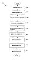
図8は、音響信号の雑音低減を実行する例示的な方法を表すフローチャートである。図8の各ステップは、任意の順序で実行されることができる。また、図8の方法は、例示されるより、追加のステップを含んでもよいし、より少ないステップであってもよい。 FIG. 8 is a flowchart representing an exemplary method for performing noise reduction of an acoustic signal. The steps of FIG. 8 can be performed in any order. Also, the method of FIG. 8 may include additional steps or fewer steps than illustrated.
ステップ802において、音響信号が、主たるマイク106と補助的なマイク108により、受信される。例示的な実施形態において、音響信号は、処理のために、デジタル形式へと変換される。いくつかの実施形態において、音響信号は、二つより多い、あるいは二つより少ないマイクから、受信される。
In
ステップ804において、音響信号についての周波数分析が実行され、音響信号を、サブバンド信号へと分離する。周波数分析は、フィルタバンクか、あるいは、例えば離散フーリエ変換若しくは離散コサイン変換を利用することができる。
In
ステップ806において、主たるマイクと補助的なマイクの両方で受信された音響信号のサブバンド信号のエネルギースペクトルが、計算される。エネルギー推定が計算されると、ステップ808において、マイク間のレベル差(ILD)が計算される。一実施形態において、ILDは、主たる音響信号と、補助的な音響信号の両方のエネルギー推定(すなわち、エネルギースペクトル)に基づいて、計算される。
In
ステップ810において、音声成分及び雑音成分は、適応的に、分類される。ステップ810は、受信されたエネルギー推定を分析し、可能であれば、音声を、音響信号の雑音と区別するために、ILDを分析する。 In step 810, the speech and noise components are adaptively classified. Step 810 analyzes the received energy estimate and, if possible, analyzes the ILD to distinguish speech from noise in the acoustic signal.
ステップ812において、サブバンド信号の雑音スペクトルが、決定される。複数の実施形態において、各サブバンド信号の雑音推定は、主たるマイク106において受信される、主たる音響信号に基づく。雑音推定は、主たるマイク106から受信された、主たる音響信号のサブバンド信号に対する現在のエネルギー推定と、以前に計算された雑音推定に基づき得る。雑音推定を決定する際に、例示的な実施形態に従い、IDLが増加したときに、雑音推定を凍結してもよいし、あるいは、そのペースを落としてもよい。
In
ステップ813において、雑音消去が実行される。ステップ814において、雑音抑制が実行される。雑音抑制処理については、図9において、以下でより詳細に説明する。ステップ816において、雑音抑制済みの音響信号は、ユーザへと出力され得る。いくつかの実施形態において、デジタル音響信号は、出力のために、アナログ信号へと変換される。出力は、例えば、スピーカ、イヤホン又は他の同様の装置を用いて、なされ得る。
In
図9は、音響信号の雑音抑制を実行する例示的な方法を表すフローチャートである。図9の各ステップは、任意の順序で実行されてもよい。また、図9の方法は、例示されるより、追加のステップを含んでもよいし、より少ないステップで実行されてもよい。 FIG. 9 is a flowchart illustrating an exemplary method for performing noise suppression of an acoustic signal. Each step of FIG. 9 may be performed in an arbitrary order. Also, the method of FIG. 9 may include additional steps or be performed in fewer steps than illustrated.
ステップ900において、サブバンド信号のウィーナフィルタゲインが、計算される。ステップ901において、主たる音響信号の各サブバンド信号の、推定信号対雑音比が計算される。SNRは、長期ピーク音声エネルギーの瞬間的な雑音エネルギーに対する割合として表される、瞬間のSNRであってもよい。
In
ステップ902において、各サブバンド信号の最小ゲイン下限
In
![]()
![]()
ステップ904において、最終的なゲイン下限は、各サブバンド信号に対して、決定される。最終的なゲイン下限は、最小ゲイン下限を制限することにより、決定され得る。最終的なゲイン下限は、サブバンド信号における雑音成分のエネルギーレベルが、少なくとも、残留雑音目標レベルまで低減されるという制約を受ける。
In
ステップ906において、各サブバンド信号に対する、最終的なゲイン下限の最大値と、ウィーナフィルタゲインは、NPNSモジュール310により出力される、主たる音響信号についての、対応する、雑音の減ぜられたサブバンド信号により、乗算される。乗算により、雑音の減ぜられたサブバンド信号における、雑音のレベルを低減し、雑音低減をもたらす。
In
ステップ908において、主たる音響信号の、マスクされたサブバンド信号は、時間領域へと変換される。例示的な変換技術は、マスクされたサブバンド信号を合成するために、蝸牛チャンネルの逆(inverse)周波数を、マスクされたサブバンド信号へと適用する。ステップ908において、快適雑音を適用するような、追加の後処理が実行されてもよい。いくつかの実施形態において、快適雑音は、加算器を用いて、適用される。
In
本明細書で説明された雑音低減技術は、サブバンド信号に乗算されるゲインマスクとして、低減値を実現し、サブバンド信号の雑音成分のエネルギーレベルを抑制する。かかる処理は、乗法性雑音抑制とよばれる。実施形態において、本明細書で説明された雑音低減技術は、さらに、あるいは代替的に、減法性(subtractive)雑音消去処理において、利用されてもよい。そのような場合には、低減値は、例えば、任意に雑音消去されたサブバンド信号と、元の雑音のある主たるサブバンド信号との間のクロスフェード値を制御することにより、サブバンド信号において実行される雑音消去の量に対する下限を提供するために、求められる。減算性雑音消去処理は、例えば、NPNSモジュール310において、実行され得る。 The noise reduction technique described in this specification realizes a reduction value as a gain mask multiplied by the subband signal, and suppresses the energy level of the noise component of the subband signal. Such processing is called multiplicative noise suppression. In embodiments, the noise reduction techniques described herein may additionally or alternatively be utilized in a subtractive noise cancellation process. In such a case, the reduced value is determined in the subband signal, for example, by controlling the crossfade value between the arbitrarily denoised subband signal and the original noisy main subband signal. It is sought to provide a lower bound on the amount of noise cancellation performed. The subtractive noise cancellation process can be executed in the NPNS module 310, for example.
図3、4に関して説明されたものを含む、上述したモジュールは、コンピュータ読取可能な媒体(例えば、コンピュータ読取可能な媒体)のような、記憶媒体に保管される命令として、含まれ得る。これらの命令は、プロセッサ202によって読み出され、実行され、上述した機能を実行することができる。いくつかの命令の例は、ソフトウェア、プログラムコード及びファームウェアを含む。記憶媒体の例は、メモリ装置及び集積回路を含む。
The modules described above, including those described with respect to FIGS. 3 and 4, may be included as instructions stored on a storage medium, such as a computer readable medium (eg, a computer readable medium). These instructions can be read and executed by the
本発明は、上述した、好ましい実施形態及び実施例への参照によって開示されるが、かかる例は、例示的なものであり、限定する意図をもってなされたものではない点に留意する。修正及び組み合わせは、容易に当業者の頭に思い浮かぶであろうことが予期される。これらの修正及び組み合わせは、本発明の精神及び以下のクレームの範囲内にある。 Although the present invention is disclosed by reference to the preferred embodiments and examples described above, it is noted that such examples are illustrative and not intended to be limiting. It is expected that modifications and combinations will readily occur to those skilled in the art. These modifications and combinations are within the spirit of the invention and the scope of the following claims.
Claims (23)
音響信号を受信する段階と;
前記音響信号を、複数のサブバンド信号へと分離する段階と;
低減値を前記複数のサブバンド信号のうちの一のサブバンド信号に適用する段階であって、前記サブバンド信号の雑音成分のエネルギーレベルを低減させ、
前記低減値は、前記サブバンド信号の推定された信号対雑音比と、前記サブバンド信号における音声損失歪みの推定された閾値レベルとに基づく、段階と;
を有する、方法。 A method for reducing noise in an acoustic signal:
Receiving an acoustic signal;
Separating the acoustic signal into a plurality of subband signals;
Applying a reduction value to one subband signal of the plurality of subband signals, reducing an energy level of a noise component of the subband signal;
The reduction value is based on an estimated signal-to-noise ratio of the subband signal and an estimated threshold level of speech loss distortion in the subband signal;
Having a method.
請求項1に記載の方法。 Applying the reduced value comprises performing noise cancellation of the subband signal based on the reduced value;
The method of claim 1.
請求項1に記載の方法。 Applying the reduced value comprises multiplying the subband signal by the reduced value;
The method of claim 1.
をさらに有する、請求項2に記載の方法。 The method of claim 2, further comprising: multiplying the subband signal by a second reduction value, further reducing the energy level of the noise component.
請求項1に記載の方法。 The energy level of the noise component in the subband signal is reduced to at least a residual noise target level;
The method of claim 1.
前記サブバンド信号における、前記雑音成分のエネルギーレベルの、前記残留雑音目標レベルへの低減に基づいて、前記低減値の第二の値を決定する段階と;
前記低減値として、前記第一の値と前記第二の値のうち一を選択する段階と;
をさらに有する、請求項5に記載の方法。 Determining a first value of the reduction value based on the estimated signal-to-noise ratio and an estimated threshold level of the speech loss distortion;
Determining a second value of the reduction value based on a reduction in the energy level of the noise component in the subband signal to the residual noise target level;
Selecting one of the first value and the second value as the reduction value;
6. The method of claim 5, further comprising:
をさらに有する、請求項6に記載の方法。 The method of claim 6, further comprising: encoding the separated acoustic signal after reducing the reduction value.
請求項5に記載の方法。 The residual noise target level is lower than an audible level;
The method of claim 5.
請求項5に記載の方法。 The second reduction value is 1 when the energy level of the noise component of the second subband signal is lower than the residual noise target level.
The method of claim 5.
請求項1に記載の方法。 The reduction value is further based on an estimated power spectral density of the noise component and the speech component in the subband signal.
The method of claim 1.
音響信号を受信する段階と;
前記音響信号を、複数のサブバンド信号へと分離する段階と;
低減値を前記複数のサブバンド信号のうちの一のサブバンド信号に適用する段階であって、前記サブバンド信号の雑音成分のエネルギーレベルを低減させ、
前記低減値は、前記サブバンド信号の推定された信号対雑音比と、前記サブバンド信号における音声損失歪みの推定された閾値レベルとに基づく、段階と;
を有する、記憶媒体。 A computer-readable storage medium for storing a program, wherein the program causes a processor to perform a method for reducing noise in an acoustic signal, the method comprising:
Receiving an acoustic signal;
Separating the acoustic signal into a plurality of subband signals;
Applying a reduction value to one subband signal of the plurality of subband signals, reducing an energy level of a noise component of the subband signal;
The reduction value is based on an estimated signal-to-noise ratio of the subband signal and an estimated threshold level of speech loss distortion in the subband signal;
A storage medium.
請求項11に記載の記憶媒体。 Applying the reduced value comprises performing noise cancellation of the subband signal based on the reduced value;
The storage medium according to claim 11.
請求項11に記載の記憶媒体。 Applying the reduced value comprises multiplying the subband signal by the reduced value;
The storage medium according to claim 11.
請求項11に記載の記憶媒体。 The energy level of the noise component in the subband signal is reduced to at least a residual noise target level;
The storage medium according to claim 11.
前記推定された信号対雑音比と、前記音声損失歪みの推定された閾値レベルとに基づいて、前記低減値の第一の値を決定する段階と;
前記サブバンド信号における、前記雑音成分のエネルギーレベルの、前記残留雑音目標レベルへの低減に基づいて、前記低減値の第二の値を決定する段階と;
前記低減値として、前記第一の値と前記第二の値のうち一を選択する段階と;
をさらに有する、請求項14に記載の記憶媒体。 The method is:
Determining a first value of the reduction value based on the estimated signal-to-noise ratio and an estimated threshold level of the speech loss distortion;
Determining a second value of the reduction value based on a reduction in the energy level of the noise component in the subband signal to the residual noise target level;
Selecting one of the first value and the second value as the reduction value;
The storage medium according to claim 14, further comprising:
第二の低減値を、前記サブバンド信号に乗算する段階であって、さらに前記雑音成分のエネルギーレベルを低減する、段階
をさらに有する、請求項11に記載の記憶媒体。 The method
The storage medium of claim 11, further comprising: multiplying the subband signal by a second reduction value, further reducing the energy level of the noise component.
請求項14に記載の記憶媒体。 The residual noise target level is lower than an audible level;
The storage medium according to claim 14.
請求項14に記載の記憶媒体。 The second reduction value is 1 when the energy level of the noise component of the second subband signal is lower than the residual noise target level.
The storage medium according to claim 14.
プロセッサにより実行される、メモリに保管された周波数分析モジュール及び雑音低減モジュールを有し、
前記周波数分析モジュールは、
音響信号を受信し、
前記音響信号を、複数のサブバンド信号へと分離し;
前記雑音低減モジュールは、
低減値を前記複数のサブバンド信号のうちの一のサブバンド信号に適用し、前記サブバンド信号の雑音成分のエネルギーレベルを低減させ、
前記低減値は、前記サブバンド信号の推定された信号対雑音比と、前記サブバンド信号における音声損失歪みの推定された閾値レベルとに基づく、
システム。 A system for reducing noise in an acoustic signal:
Having a frequency analysis module and a noise reduction module stored in memory, executed by a processor;
The frequency analysis module includes:
Receive acoustic signals,
Separating the acoustic signal into a plurality of subband signals;
The noise reduction module includes:
Applying a reduction value to one of the plurality of subband signals to reduce the energy level of the noise component of the subband signal;
The reduction value is based on an estimated signal to noise ratio of the subband signal and an estimated threshold level of speech loss distortion in the subband signal.
system.
請求項19に記載のシステム。 The noise reduction module performs noise cancellation of the subband signal based on the reduction value;
The system of claim 19.
請求項19に記載のシステム。 The noise reduction module multiplies the subband signal by the reduction value.
The system of claim 19.
請求項19に記載のシステム。 The energy level of the noise component in the subband signal is reduced to at least a residual noise target level;
The system of claim 19.
請求項19に記載のシステム。 The reduction value is further based on input received via the noise reduction module application program interface,
The system of claim 19.
Applications Claiming Priority (5)
| Application Number | Priority Date | Filing Date | Title |
|---|---|---|---|
| US32576410P | 2010-04-19 | 2010-04-19 | |
| US61/325,764 | 2010-04-19 | ||
| US12/832,901 | 2010-07-08 | ||
| US12/832,901 US8473287B2 (en) | 2010-04-19 | 2010-07-08 | Method for jointly optimizing noise reduction and voice quality in a mono or multi-microphone system |
| PCT/US2011/032578 WO2011133405A1 (en) | 2010-04-19 | 2011-04-14 | Method for jointly optimizing noise reduction and voice quality in a mono or multi-microphone system |
Publications (2)
| Publication Number | Publication Date |
|---|---|
| JP2013525843A true JP2013525843A (en) | 2013-06-20 |
| JP2013525843A5 JP2013525843A5 (en) | 2014-05-22 |
Family
ID=44788878
Family Applications (1)
| Application Number | Title | Priority Date | Filing Date |
|---|---|---|---|
| JP2013506188A Pending JP2013525843A (en) | 2010-04-19 | 2011-04-14 | Method for optimizing both noise reduction and speech quality in a system with single or multiple microphones |
Country Status (5)
| Country | Link |
|---|---|
| US (4) | US8473287B2 (en) |
| JP (1) | JP2013525843A (en) |
| KR (1) | KR20130061673A (en) |
| TW (1) | TW201207845A (en) |
| WO (1) | WO2011133405A1 (en) |
Cited By (4)
| Publication number | Priority date | Publication date | Assignee | Title |
|---|---|---|---|---|
| US9437180B2 (en) | 2010-01-26 | 2016-09-06 | Knowles Electronics, Llc | Adaptive noise reduction using level cues |
| US9502048B2 (en) | 2010-04-19 | 2016-11-22 | Knowles Electronics, Llc | Adaptively reducing noise to limit speech distortion |
| US9830899B1 (en) | 2006-05-25 | 2017-11-28 | Knowles Electronics, Llc | Adaptive noise cancellation |
| US11056128B2 (en) | 2016-10-18 | 2021-07-06 | Fraunhofer-Gesellschaft Zur Foerderung Der Angewandten Forschung E.V. | Apparatus and method for processing an audio signal using noise suppression filter values |
Families Citing this family (80)
| Publication number | Priority date | Publication date | Assignee | Title |
|---|---|---|---|---|
| US20110125497A1 (en) * | 2009-11-20 | 2011-05-26 | Takahiro Unno | Method and System for Voice Activity Detection |
| US9838784B2 (en) | 2009-12-02 | 2017-12-05 | Knowles Electronics, Llc | Directional audio capture |
| US8538035B2 (en) | 2010-04-29 | 2013-09-17 | Audience, Inc. | Multi-microphone robust noise suppression |
| US8798290B1 (en) | 2010-04-21 | 2014-08-05 | Audience, Inc. | Systems and methods for adaptive signal equalization |
| US8781137B1 (en) | 2010-04-27 | 2014-07-15 | Audience, Inc. | Wind noise detection and suppression |
| US8798992B2 (en) * | 2010-05-19 | 2014-08-05 | Disney Enterprises, Inc. | Audio noise modification for event broadcasting |
| US9558755B1 (en) | 2010-05-20 | 2017-01-31 | Knowles Electronics, Llc | Noise suppression assisted automatic speech recognition |
| US8447596B2 (en) | 2010-07-12 | 2013-05-21 | Audience, Inc. | Monaural noise suppression based on computational auditory scene analysis |
| EP2603914A4 (en) * | 2010-08-11 | 2014-11-19 | Bone Tone Comm Ltd | Background sound removal for privacy and personalization use |
| US9772815B1 (en) | 2013-11-14 | 2017-09-26 | Knowles Electronics, Llc | Personalized operation of a mobile device using acoustic and non-acoustic information |
| US10353495B2 (en) | 2010-08-20 | 2019-07-16 | Knowles Electronics, Llc | Personalized operation of a mobile device using sensor signatures |
| US20140006019A1 (en) * | 2011-03-18 | 2014-01-02 | Nokia Corporation | Apparatus for audio signal processing |
| US8972251B2 (en) * | 2011-06-07 | 2015-03-03 | Qualcomm Incorporated | Generating a masking signal on an electronic device |
| EP2590165B1 (en) | 2011-11-07 | 2015-04-29 | Dietmar Ruwisch | Method and apparatus for generating a noise reduced audio signal |
| US20130282372A1 (en) * | 2012-04-23 | 2013-10-24 | Qualcomm Incorporated | Systems and methods for audio signal processing |
| US9159964B2 (en) | 2012-09-25 | 2015-10-13 | Front Edge Technology, Inc. | Solid state battery having mismatched battery cells |
| US9640194B1 (en) | 2012-10-04 | 2017-05-02 | Knowles Electronics, Llc | Noise suppression for speech processing based on machine-learning mask estimation |
| US9424859B2 (en) * | 2012-11-21 | 2016-08-23 | Harman International Industries Canada Ltd. | System to control audio effect parameters of vocal signals |
| US9330677B2 (en) | 2013-01-07 | 2016-05-03 | Dietmar Ruwisch | Method and apparatus for generating a noise reduced audio signal using a microphone array |
| US9536540B2 (en) | 2013-07-19 | 2017-01-03 | Knowles Electronics, Llc | Speech signal separation and synthesis based on auditory scene analysis and speech modeling |
| CN106409310B (en) * | 2013-08-06 | 2019-11-19 | 华为技术有限公司 | A kind of audio signal classification method and apparatus |
| US9508345B1 (en) | 2013-09-24 | 2016-11-29 | Knowles Electronics, Llc | Continuous voice sensing |
| US9781106B1 (en) | 2013-11-20 | 2017-10-03 | Knowles Electronics, Llc | Method for modeling user possession of mobile device for user authentication framework |
| US9953634B1 (en) | 2013-12-17 | 2018-04-24 | Knowles Electronics, Llc | Passive training for automatic speech recognition |
| JP6337519B2 (en) * | 2014-03-03 | 2018-06-06 | 富士通株式会社 | Speech processing apparatus, noise suppression method, and program |
| US9437188B1 (en) | 2014-03-28 | 2016-09-06 | Knowles Electronics, Llc | Buffered reprocessing for multi-microphone automatic speech recognition assist |
| US9500739B2 (en) | 2014-03-28 | 2016-11-22 | Knowles Electronics, Llc | Estimating and tracking multiple attributes of multiple objects from multi-sensor data |
| US10446168B2 (en) * | 2014-04-02 | 2019-10-15 | Plantronics, Inc. | Noise level measurement with mobile devices, location services, and environmental response |
| US9807725B1 (en) | 2014-04-10 | 2017-10-31 | Knowles Electronics, Llc | Determining a spatial relationship between different user contexts |
| US10419851B2 (en) | 2014-04-17 | 2019-09-17 | Cirrus Logic, Inc. | Retaining binaural cues when mixing microphone signals |
| US9799330B2 (en) | 2014-08-28 | 2017-10-24 | Knowles Electronics, Llc | Multi-sourced noise suppression |
| WO2016040885A1 (en) | 2014-09-12 | 2016-03-17 | Audience, Inc. | Systems and methods for restoration of speech components |
| US9712915B2 (en) | 2014-11-25 | 2017-07-18 | Knowles Electronics, Llc | Reference microphone for non-linear and time variant echo cancellation |
| DE102015201073A1 (en) | 2015-01-22 | 2016-07-28 | Sivantos Pte. Ltd. | Method and apparatus for noise suppression based on inter-subband correlation |
| WO2016123560A1 (en) | 2015-01-30 | 2016-08-04 | Knowles Electronics, Llc | Contextual switching of microphones |
| US9401158B1 (en) | 2015-09-14 | 2016-07-26 | Knowles Electronics, Llc | Microphone signal fusion |
| US10297269B2 (en) | 2015-09-24 | 2019-05-21 | Dolby Laboratories Licensing Corporation | Automatic calculation of gains for mixing narration into pre-recorded content |
| WO2017096174A1 (en) | 2015-12-04 | 2017-06-08 | Knowles Electronics, Llc | Multi-microphone feedforward active noise cancellation |
| US9779716B2 (en) | 2015-12-30 | 2017-10-03 | Knowles Electronics, Llc | Occlusion reduction and active noise reduction based on seal quality |
| US9830930B2 (en) | 2015-12-30 | 2017-11-28 | Knowles Electronics, Llc | Voice-enhanced awareness mode |
| US20170195811A1 (en) | 2015-12-30 | 2017-07-06 | Knowles Electronics Llc | Audio Monitoring and Adaptation Using Headset Microphones Inside User's Ear Canal |
| WO2017127646A1 (en) | 2016-01-22 | 2017-07-27 | Knowles Electronics, Llc | Shared secret voice authentication |
| US9812149B2 (en) | 2016-01-28 | 2017-11-07 | Knowles Electronics, Llc | Methods and systems for providing consistency in noise reduction during speech and non-speech periods |
| US10157629B2 (en) * | 2016-02-05 | 2018-12-18 | Brainchip Inc. | Low power neuromorphic voice activation system and method |
| US10923132B2 (en) | 2016-02-19 | 2021-02-16 | Dolby Laboratories Licensing Corporation | Diffusivity based sound processing method and apparatus |
| US9820042B1 (en) | 2016-05-02 | 2017-11-14 | Knowles Electronics, Llc | Stereo separation and directional suppression with omni-directional microphones |
| US10249305B2 (en) * | 2016-05-19 | 2019-04-02 | Microsoft Technology Licensing, Llc | Permutation invariant training for talker-independent multi-talker speech separation |
| FR3056813B1 (en) * | 2016-09-29 | 2019-11-08 | Dolphin Integration | AUDIO CIRCUIT AND METHOD OF DETECTING ACTIVITY |
| WO2018148095A1 (en) | 2017-02-13 | 2018-08-16 | Knowles Electronics, Llc | Soft-talk audio capture for mobile devices |
| US10224053B2 (en) * | 2017-03-24 | 2019-03-05 | Hyundai Motor Company | Audio signal quality enhancement based on quantitative SNR analysis and adaptive Wiener filtering |
| EP3428918B1 (en) * | 2017-07-11 | 2020-02-12 | Harman Becker Automotive Systems GmbH | Pop noise control |
| US11263522B2 (en) | 2017-09-08 | 2022-03-01 | Analog Devices, Inc. | Analog switched-capacitor neural network |
| US10096311B1 (en) | 2017-09-12 | 2018-10-09 | Plantronics, Inc. | Intelligent soundscape adaptation utilizing mobile devices |
| US20190090052A1 (en) | 2017-09-20 | 2019-03-21 | Knowles Electronics, Llc | Cost effective microphone array design for spatial filtering |
| US10339949B1 (en) | 2017-12-19 | 2019-07-02 | Apple Inc. | Multi-channel speech enhancement |
| US10957337B2 (en) | 2018-04-11 | 2021-03-23 | Microsoft Technology Licensing, Llc | Multi-microphone speech separation |
| CN109003622B (en) * | 2018-09-11 | 2021-06-04 | 广州小鹏汽车科技有限公司 | Noise reduction processing method and device, radio and vehicle |
| CN110517680B (en) * | 2018-11-15 | 2023-02-03 | 腾讯科技(深圳)有限公司 | Artificial intelligence data detection method and device and storage medium |
| US10771887B2 (en) * | 2018-12-21 | 2020-09-08 | Cisco Technology, Inc. | Anisotropic background audio signal control |
| US11170799B2 (en) * | 2019-02-13 | 2021-11-09 | Harman International Industries, Incorporated | Nonlinear noise reduction system |
| US10964314B2 (en) * | 2019-03-22 | 2021-03-30 | Cirrus Logic, Inc. | System and method for optimized noise reduction in the presence of speech distortion using adaptive microphone array |
| EP3764358B1 (en) | 2019-07-10 | 2024-05-22 | Analog Devices International Unlimited Company | Signal processing methods and systems for beam forming with wind buffeting protection |
| EP3764664A1 (en) | 2019-07-10 | 2021-01-13 | Analog Devices International Unlimited Company | Signal processing methods and systems for beam forming with microphone tolerance compensation |
| EP3764660B1 (en) | 2019-07-10 | 2023-08-30 | Analog Devices International Unlimited Company | Signal processing methods and systems for adaptive beam forming |
| EP3764359B1 (en) | 2019-07-10 | 2024-08-28 | Analog Devices International Unlimited Company | Signal processing methods and systems for multi-focus beam-forming |
| EP3764360B1 (en) | 2019-07-10 | 2024-05-01 | Analog Devices International Unlimited Company | Signal processing methods and systems for beam forming with improved signal to noise ratio |
| US11587575B2 (en) * | 2019-10-11 | 2023-02-21 | Plantronics, Inc. | Hybrid noise suppression |
| US11238853B2 (en) | 2019-10-30 | 2022-02-01 | Comcast Cable Communications, Llc | Keyword-based audio source localization |
| CN113038318B (en) * | 2019-12-25 | 2022-06-07 | 荣耀终端有限公司 | Voice signal processing method and device |
| TWI760676B (en) * | 2020-01-07 | 2022-04-11 | 瑞昱半導體股份有限公司 | Audio playback apparatus and method having noise-canceling mechanism |
| KR20210101670A (en) | 2020-02-10 | 2021-08-19 | 삼성전자주식회사 | Electronic device and method of reducing noise using the same |
| US11053017B1 (en) * | 2020-08-20 | 2021-07-06 | Kitty Hawk Corporation | Rotor noise reduction using signal processing |
| CN112289333B (en) * | 2020-12-25 | 2021-04-13 | 北京达佳互联信息技术有限公司 | Training method and device of voice enhancement model and voice enhancement method and device |
| US12112741B2 (en) * | 2021-02-18 | 2024-10-08 | Microsoft Technology Licensing, Llc | System and method for data augmentation and speech processing in dynamic acoustic environments |
| CN113409813B (en) * | 2021-05-26 | 2023-06-06 | 北京捷通华声科技股份有限公司 | Voice separation method and device |
| US12028684B2 (en) | 2021-07-30 | 2024-07-02 | Starkey Laboratories, Inc. | Spatially differentiated noise reduction for hearing devices |
| US20230230582A1 (en) * | 2022-01-20 | 2023-07-20 | Nuance Communications, Inc. | Data augmentation system and method for multi-microphone systems |
| US20230230580A1 (en) * | 2022-01-20 | 2023-07-20 | Nuance Communications, Inc. | Data augmentation system and method for multi-microphone systems |
| US20230230599A1 (en) * | 2022-01-20 | 2023-07-20 | Nuance Communications, Inc. | Data augmentation system and method for multi-microphone systems |
| US20230230581A1 (en) * | 2022-01-20 | 2023-07-20 | Nuance Communications, Inc. | Data augmentation system and method for multi-microphone systems |
Citations (4)
| Publication number | Priority date | Publication date | Assignee | Title |
|---|---|---|---|---|
| JP2003140700A (en) * | 2001-11-05 | 2003-05-16 | Nec Corp | Method and device for noise removal |
| JP2008065090A (en) * | 2006-09-07 | 2008-03-21 | Toshiba Corp | Noise suppressing apparatus |
| US20090012783A1 (en) * | 2007-07-06 | 2009-01-08 | Audience, Inc. | System and method for adaptive intelligent noise suppression |
| WO2010005493A1 (en) * | 2008-06-30 | 2010-01-14 | Audience, Inc. | System and method for providing noise suppression utilizing null processing noise subtraction |
Family Cites Families (314)
| Publication number | Priority date | Publication date | Assignee | Title |
|---|---|---|---|---|
| US3581122A (en) | 1967-10-26 | 1971-05-25 | Bell Telephone Labor Inc | All-pass filter circuit having negative resistance shunting resonant circuit |
| US3989897A (en) | 1974-10-25 | 1976-11-02 | Carver R W | Method and apparatus for reducing noise content in audio signals |
| US4630304A (en) | 1985-07-01 | 1986-12-16 | Motorola, Inc. | Automatic background noise estimator for a noise suppression system |
| US4811404A (en) | 1987-10-01 | 1989-03-07 | Motorola, Inc. | Noise suppression system |
| US4910779A (en) | 1987-10-15 | 1990-03-20 | Cooper Duane H | Head diffraction compensated stereo system with optimal equalization |
| IL84948A0 (en) | 1987-12-25 | 1988-06-30 | D S P Group Israel Ltd | Noise reduction system |
| US4991166A (en) | 1988-10-28 | 1991-02-05 | Shure Brothers Incorporated | Echo reduction circuit |
| US5027306A (en) | 1989-05-12 | 1991-06-25 | Dattorro Jon C | Decimation filter as for a sigma-delta analog-to-digital converter |
| US5050217A (en) | 1990-02-16 | 1991-09-17 | Akg Acoustics, Inc. | Dynamic noise reduction and spectral restoration system |
| US5103229A (en) | 1990-04-23 | 1992-04-07 | General Electric Company | Plural-order sigma-delta analog-to-digital converters using both single-bit and multiple-bit quantization |
| JPH0566795A (en) | 1991-09-06 | 1993-03-19 | Gijutsu Kenkyu Kumiai Iryo Fukushi Kiki Kenkyusho | Noise suppressing device and its adjustment device |
| JP3279612B2 (en) | 1991-12-06 | 2002-04-30 | ソニー株式会社 | Noise reduction device |
| JP3176474B2 (en) | 1992-06-03 | 2001-06-18 | 沖電気工業株式会社 | Adaptive noise canceller device |
| JP2508574B2 (en) | 1992-11-10 | 1996-06-19 | 日本電気株式会社 | Multi-channel eco-removal device |
| US5408235A (en) | 1994-03-07 | 1995-04-18 | Intel Corporation | Second order Sigma-Delta based analog to digital converter having superior analog components and having a programmable comb filter coupled to the digital signal processor |
| US5544250A (en) | 1994-07-18 | 1996-08-06 | Motorola | Noise suppression system and method therefor |
| JP3307138B2 (en) | 1995-02-27 | 2002-07-24 | ソニー株式会社 | Signal encoding method and apparatus, and signal decoding method and apparatus |
| US5828997A (en) | 1995-06-07 | 1998-10-27 | Sensimetrics Corporation | Content analyzer mixing inverse-direction-probability-weighted noise to input signal |
| US5809463A (en) | 1995-09-15 | 1998-09-15 | Hughes Electronics | Method of detecting double talk in an echo canceller |
| US5687104A (en) | 1995-11-17 | 1997-11-11 | Motorola, Inc. | Method and apparatus for generating decoupled filter parameters and implementing a band decoupled filter |
| FI100840B (en) | 1995-12-12 | 1998-02-27 | Nokia Mobile Phones Ltd | Noise attenuator and method for attenuating background noise from noisy speech and a mobile station |
| US5819217A (en) | 1995-12-21 | 1998-10-06 | Nynex Science & Technology, Inc. | Method and system for differentiating between speech and noise |
| US5937060A (en) | 1996-02-09 | 1999-08-10 | Texas Instruments Incorporated | Residual echo suppression |
| US5774562A (en) | 1996-03-25 | 1998-06-30 | Nippon Telegraph And Telephone Corp. | Method and apparatus for dereverberation |
| JP3325770B2 (en) | 1996-04-26 | 2002-09-17 | 三菱電機株式会社 | Noise reduction circuit, noise reduction device, and noise reduction method |
| US5701350A (en) | 1996-06-03 | 1997-12-23 | Digisonix, Inc. | Active acoustic control in remote regions |
| US5825898A (en) | 1996-06-27 | 1998-10-20 | Lamar Signal Processing Ltd. | System and method for adaptive interference cancelling |
| US5796819A (en) | 1996-07-24 | 1998-08-18 | Ericsson Inc. | Echo canceller for non-linear circuits |
| US5806025A (en) | 1996-08-07 | 1998-09-08 | U S West, Inc. | Method and system for adaptive filtering of speech signals using signal-to-noise ratio to choose subband filter bank |
| US5887032A (en) | 1996-09-03 | 1999-03-23 | Amati Communications Corp. | Method and apparatus for crosstalk cancellation |
| JPH10124088A (en) | 1996-10-24 | 1998-05-15 | Sony Corp | Device and method for expanding voice frequency band width |
| US5963651A (en) | 1997-01-16 | 1999-10-05 | Digisonix, Inc. | Adaptive acoustic attenuation system having distributed processing and shared state nodal architecture |
| JP3328532B2 (en) | 1997-01-22 | 2002-09-24 | シャープ株式会社 | Digital data encoding method |
| US5933495A (en) | 1997-02-07 | 1999-08-03 | Texas Instruments Incorporated | Subband acoustic noise suppression |
| US6104993A (en) | 1997-02-26 | 2000-08-15 | Motorola, Inc. | Apparatus and method for rate determination in a communication system |
| US6151397A (en) | 1997-05-16 | 2000-11-21 | Motorola, Inc. | Method and system for reducing undesired signals in a communication environment |
| TW392416B (en) | 1997-08-18 | 2000-06-01 | Noise Cancellation Tech | Noise cancellation system for active headsets |
| US6122384A (en) | 1997-09-02 | 2000-09-19 | Qualcomm Inc. | Noise suppression system and method |
| JP4132154B2 (en) | 1997-10-23 | 2008-08-13 | ソニー株式会社 | Speech synthesis method and apparatus, and bandwidth expansion method and apparatus |
| US6343267B1 (en) | 1998-04-30 | 2002-01-29 | Matsushita Electric Industrial Co., Ltd. | Dimensionality reduction for speaker normalization and speaker and environment adaptation using eigenvoice techniques |
| US6549586B2 (en) | 1999-04-12 | 2003-04-15 | Telefonaktiebolaget L M Ericsson | System and method for dual microphone signal noise reduction using spectral subtraction |
| US6160265A (en) | 1998-07-13 | 2000-12-12 | Kensington Laboratories, Inc. | SMIF box cover hold down latch and box door latch actuating mechanism |
| US6240386B1 (en) | 1998-08-24 | 2001-05-29 | Conexant Systems, Inc. | Speech codec employing noise classification for noise compensation |
| US6539355B1 (en) | 1998-10-15 | 2003-03-25 | Sony Corporation | Signal band expanding method and apparatus and signal synthesis method and apparatus |
| US6011501A (en) | 1998-12-31 | 2000-01-04 | Cirrus Logic, Inc. | Circuits, systems and methods for processing data in a one-bit format |
| US6453287B1 (en) | 1999-02-04 | 2002-09-17 | Georgia-Tech Research Corporation | Apparatus and quality enhancement algorithm for mixed excitation linear predictive (MELP) and other speech coders |
| US6381570B2 (en) | 1999-02-12 | 2002-04-30 | Telogy Networks, Inc. | Adaptive two-threshold method for discriminating noise from speech in a communication signal |
| US6377915B1 (en) | 1999-03-17 | 2002-04-23 | Yrp Advanced Mobile Communication Systems Research Laboratories Co., Ltd. | Speech decoding using mix ratio table |
| SE514948C2 (en) | 1999-03-29 | 2001-05-21 | Ericsson Telefon Ab L M | Method and apparatus for reducing crosstalk |
| US6490556B2 (en) | 1999-05-28 | 2002-12-03 | Intel Corporation | Audio classifier for half duplex communication |
| US20010044719A1 (en) | 1999-07-02 | 2001-11-22 | Mitsubishi Electric Research Laboratories, Inc. | Method and system for recognizing, indexing, and searching acoustic signals |
| US6453284B1 (en) | 1999-07-26 | 2002-09-17 | Texas Tech University Health Sciences Center | Multiple voice tracking system and method |
| US6480610B1 (en) | 1999-09-21 | 2002-11-12 | Sonic Innovations, Inc. | Subband acoustic feedback cancellation in hearing aids |
| US7054809B1 (en) | 1999-09-22 | 2006-05-30 | Mindspeed Technologies, Inc. | Rate selection method for selectable mode vocoder |
| US6326912B1 (en) | 1999-09-24 | 2001-12-04 | Akm Semiconductor, Inc. | Analog-to-digital conversion using a multi-bit analog delta-sigma modulator combined with a one-bit digital delta-sigma modulator |
| US6594367B1 (en) | 1999-10-25 | 2003-07-15 | Andrea Electronics Corporation | Super directional beamforming design and implementation |
| US6473733B1 (en) | 1999-12-01 | 2002-10-29 | Research In Motion Limited | Signal enhancement for voice coding |
| TW510143B (en) | 1999-12-03 | 2002-11-11 | Dolby Lab Licensing Corp | Method for deriving at least three audio signals from two input audio signals |
| US6934387B1 (en) | 1999-12-17 | 2005-08-23 | Marvell International Ltd. | Method and apparatus for digital near-end echo/near-end crosstalk cancellation with adaptive correlation |
| GB2357683A (en) | 1999-12-24 | 2001-06-27 | Nokia Mobile Phones Ltd | Voiced/unvoiced determination for speech coding |
| US6757395B1 (en) | 2000-01-12 | 2004-06-29 | Sonic Innovations, Inc. | Noise reduction apparatus and method |
| US7076315B1 (en) | 2000-03-24 | 2006-07-11 | Audience, Inc. | Efficient computation of log-frequency-scale digital filter cascade |
| US20010046304A1 (en) | 2000-04-24 | 2001-11-29 | Rast Rodger H. | System and method for selective control of acoustic isolation in headsets |
| JP2001318694A (en) | 2000-05-10 | 2001-11-16 | Toshiba Corp | Device and method for signal processing and recording medium |
| US7346176B1 (en) | 2000-05-11 | 2008-03-18 | Plantronics, Inc. | Auto-adjust noise canceling microphone with position sensor |
| US6377637B1 (en) | 2000-07-12 | 2002-04-23 | Andrea Electronics Corporation | Sub-band exponential smoothing noise canceling system |
| US20070233479A1 (en) | 2002-05-30 | 2007-10-04 | Burnett Gregory C | Detecting voiced and unvoiced speech using both acoustic and nonacoustic sensors |
| US8254617B2 (en) | 2003-03-27 | 2012-08-28 | Aliphcom, Inc. | Microphone array with rear venting |
| US6782253B1 (en) | 2000-08-10 | 2004-08-24 | Koninklijke Philips Electronics N.V. | Mobile micro portal |
| EP1407553B1 (en) | 2000-08-11 | 2006-02-22 | Koninklijke Philips Electronics N.V. | Method and arrangement for synchronizing a sigma-delta-modulator |
| JP3566197B2 (en) | 2000-08-31 | 2004-09-15 | 松下電器産業株式会社 | Noise suppression device and noise suppression method |
| US6804203B1 (en) | 2000-09-15 | 2004-10-12 | Mindspeed Technologies, Inc. | Double talk detector for echo cancellation in a speech communication system |
| US6859508B1 (en) | 2000-09-28 | 2005-02-22 | Nec Electronics America, Inc. | Four dimensional equalizer and far-end cross talk canceler in Gigabit Ethernet signals |
| US7472059B2 (en) | 2000-12-08 | 2008-12-30 | Qualcomm Incorporated | Method and apparatus for robust speech classification |
| US20020128839A1 (en) | 2001-01-12 | 2002-09-12 | Ulf Lindgren | Speech bandwidth extension |
| US20020097884A1 (en) | 2001-01-25 | 2002-07-25 | Cairns Douglas A. | Variable noise reduction algorithm based on vehicle conditions |
| US6990196B2 (en) | 2001-02-06 | 2006-01-24 | The Board Of Trustees Of The Leland Stanford Junior University | Crosstalk identification in xDSL systems |
| US7617099B2 (en) | 2001-02-12 | 2009-11-10 | FortMedia Inc. | Noise suppression by two-channel tandem spectrum modification for speech signal in an automobile |
| US7006636B2 (en) | 2002-05-24 | 2006-02-28 | Agere Systems Inc. | Coherence-based audio coding and synthesis |
| US20040153313A1 (en) | 2001-05-11 | 2004-08-05 | Roland Aubauer | Method for enlarging the band width of a narrow-band filtered voice signal, especially a voice signal emitted by a telecommunication appliance |
| US6675164B2 (en) | 2001-06-08 | 2004-01-06 | The Regents Of The University Of California | Parallel object-oriented data mining system |
| US7343282B2 (en) | 2001-06-26 | 2008-03-11 | Nokia Corporation | Method for transcoding audio signals, transcoder, network element, wireless communications network and communications system |
| US6876859B2 (en) | 2001-07-18 | 2005-04-05 | Trueposition, Inc. | Method for estimating TDOA and FDOA in a wireless location system |
| CA2354808A1 (en) | 2001-08-07 | 2003-02-07 | King Tam | Sub-band adaptive signal processing in an oversampled filterbank |
| US6895375B2 (en) | 2001-10-04 | 2005-05-17 | At&T Corp. | System for bandwidth extension of Narrow-band speech |
| US6988066B2 (en) | 2001-10-04 | 2006-01-17 | At&T Corp. | Method of bandwidth extension for narrow-band speech |
| ATE288617T1 (en) | 2001-11-29 | 2005-02-15 | Coding Tech Ab | RESTORATION OF HIGH FREQUENCY COMPONENTS |
| US7042934B2 (en) | 2002-01-23 | 2006-05-09 | Actelis Networks Inc. | Crosstalk mitigation in a modem pool environment |
| WO2007106399A2 (en) | 2006-03-10 | 2007-09-20 | Mh Acoustics, Llc | Noise-reducing directional microphone array |
| US7171008B2 (en) | 2002-02-05 | 2007-01-30 | Mh Acoustics, Llc | Reducing noise in audio systems |
| US8098844B2 (en) | 2002-02-05 | 2012-01-17 | Mh Acoustics, Llc | Dual-microphone spatial noise suppression |
| US7050783B2 (en) | 2002-02-22 | 2006-05-23 | Kyocera Wireless Corp. | Accessory detection system |
| CA2420989C (en) | 2002-03-08 | 2006-12-05 | Gennum Corporation | Low-noise directional microphone system |
| AU2003233425A1 (en) | 2002-03-22 | 2003-10-13 | Georgia Tech Research Corporation | Analog audio enhancement system using a noise suppression algorithm |
| CN1643571A (en) | 2002-03-27 | 2005-07-20 | 艾黎弗公司 | Nicrophone and voice activity detection (vad) configurations for use with communication systems |
| GB2387008A (en) | 2002-03-28 | 2003-10-01 | Qinetiq Ltd | Signal Processing System |
| US7072834B2 (en) | 2002-04-05 | 2006-07-04 | Intel Corporation | Adapting to adverse acoustic environment in speech processing using playback training data |
| US7065486B1 (en) | 2002-04-11 | 2006-06-20 | Mindspeed Technologies, Inc. | Linear prediction based noise suppression |
| US7190665B2 (en) | 2002-04-19 | 2007-03-13 | Texas Instruments Incorporated | Blind crosstalk cancellation for multicarrier modulation |
| ATE332003T1 (en) | 2002-04-22 | 2006-07-15 | Koninkl Philips Electronics Nv | PARAMETRIC DESCRIPTION OF MULTI-CHANNEL AUDIO |
| DK1359787T3 (en) | 2002-04-25 | 2015-04-20 | Gn Resound As | Fitting method and hearing prosthesis which is based on signal to noise ratio loss of data |
| US7319959B1 (en) | 2002-05-14 | 2008-01-15 | Audience, Inc. | Multi-source phoneme classification for noise-robust automatic speech recognition |
| US7257231B1 (en) | 2002-06-04 | 2007-08-14 | Creative Technology Ltd. | Stream segregation for stereo signals |
| US7242762B2 (en) | 2002-06-24 | 2007-07-10 | Freescale Semiconductor, Inc. | Monitoring and control of an adaptive filter in a communication system |
| CA2493105A1 (en) | 2002-07-19 | 2004-01-29 | British Telecommunications Public Limited Company | Method and system for classification of semantic content of audio/video data |
| CA2399159A1 (en) | 2002-08-16 | 2004-02-16 | Dspfactory Ltd. | Convergence improvement for oversampled subband adaptive filters |
| JP4155774B2 (en) | 2002-08-28 | 2008-09-24 | 富士通株式会社 | Echo suppression system and method |
| US7539273B2 (en) | 2002-08-29 | 2009-05-26 | Bae Systems Information And Electronic Systems Integration Inc. | Method for separating interfering signals and computing arrival angles |
| US7574352B2 (en) | 2002-09-06 | 2009-08-11 | Massachusetts Institute Of Technology | 2-D processing of speech |
| US6917688B2 (en) | 2002-09-11 | 2005-07-12 | Nanyang Technological University | Adaptive noise cancelling microphone system |
| US7283956B2 (en) | 2002-09-18 | 2007-10-16 | Motorola, Inc. | Noise suppression |
| WO2004030236A1 (en) | 2002-09-27 | 2004-04-08 | Globespanvirata Incorporated | Method and system for reducing interferences due to handshake tones |
| US7657427B2 (en) | 2002-10-11 | 2010-02-02 | Nokia Corporation | Methods and devices for source controlled variable bit-rate wideband speech coding |
| US7003099B1 (en) | 2002-11-15 | 2006-02-21 | Fortmedia, Inc. | Small array microphone for acoustic echo cancellation and noise suppression |
| US7359504B1 (en) | 2002-12-03 | 2008-04-15 | Plantronics, Inc. | Method and apparatus for reducing echo and noise |
| US20040105550A1 (en) | 2002-12-03 | 2004-06-03 | Aylward J. Richard | Directional electroacoustical transducing |
| US7162420B2 (en) | 2002-12-10 | 2007-01-09 | Liberato Technologies, Llc | System and method for noise reduction having first and second adaptive filters |
| EP1432222A1 (en) | 2002-12-20 | 2004-06-23 | Siemens Aktiengesellschaft | Echo canceller for compressed speech |
| KR100477699B1 (en) | 2003-01-15 | 2005-03-18 | 삼성전자주식회사 | Quantization noise shaping method and apparatus |
| GB2397990A (en) | 2003-01-31 | 2004-08-04 | Mitel Networks Corp | Echo cancellation/suppression and double-talk detection in communication paths |
| US7895036B2 (en) | 2003-02-21 | 2011-02-22 | Qnx Software Systems Co. | System for suppressing wind noise |
| US7949522B2 (en) | 2003-02-21 | 2011-05-24 | Qnx Software Systems Co. | System for suppressing rain noise |
| GB2398913B (en) | 2003-02-27 | 2005-08-17 | Motorola Inc | Noise estimation in speech recognition |
| EP1604354A4 (en) | 2003-03-15 | 2008-04-02 | Mindspeed Tech Inc | Voicing index controls for celp speech coding |
| EP1473964A3 (en) | 2003-05-02 | 2006-08-09 | Samsung Electronics Co., Ltd. | Microphone array, method to process signals from this microphone array and speech recognition method and system using the same |
| US7577084B2 (en) | 2003-05-03 | 2009-08-18 | Ikanos Communications Inc. | ISDN crosstalk cancellation in a DSL system |
| GB2401744B (en) | 2003-05-14 | 2006-02-15 | Ultra Electronics Ltd | An adaptive control unit with feedback compensation |
| JP4212591B2 (en) | 2003-06-30 | 2009-01-21 | 富士通株式会社 | Audio encoding device |
| EP1652404B1 (en) | 2003-07-11 | 2010-11-03 | Cochlear Limited | Method and device for noise reduction |
| US7289554B2 (en) | 2003-07-15 | 2007-10-30 | Brooktree Broadband Holding, Inc. | Method and apparatus for channel equalization and cyclostationary interference rejection for ADSL-DMT modems |
| US7050388B2 (en) | 2003-08-07 | 2006-05-23 | Quellan, Inc. | Method and system for crosstalk cancellation |
| US7245767B2 (en) | 2003-08-21 | 2007-07-17 | Hewlett-Packard Development Company, L.P. | Method and apparatus for object identification, classification or verification |
| US7516067B2 (en) | 2003-08-25 | 2009-04-07 | Microsoft Corporation | Method and apparatus using harmonic-model-based front end for robust speech recognition |
| US7099821B2 (en) | 2003-09-12 | 2006-08-29 | Softmax, Inc. | Separation of target acoustic signals in a multi-transducer arrangement |
| CA2452945C (en) | 2003-09-23 | 2016-05-10 | Mcmaster University | Binaural adaptive hearing system |
| US20050075866A1 (en) | 2003-10-06 | 2005-04-07 | Bernard Widrow | Speech enhancement in the presence of background noise |
| US7461003B1 (en) | 2003-10-22 | 2008-12-02 | Tellabs Operations, Inc. | Methods and apparatus for improving the quality of speech signals |
| US20060116874A1 (en) | 2003-10-24 | 2006-06-01 | Jonas Samuelsson | Noise-dependent postfiltering |
| US7672693B2 (en) | 2003-11-10 | 2010-03-02 | Nokia Corporation | Controlling method, secondary unit and radio terminal equipment |
| US7725314B2 (en) | 2004-02-16 | 2010-05-25 | Microsoft Corporation | Method and apparatus for constructing a speech filter using estimates of clean speech and noise |
| EP1719114A2 (en) | 2004-02-18 | 2006-11-08 | Philips Intellectual Property & Standards GmbH | Method and system for generating training data for an automatic speech recogniser |
| DE602004004242T2 (en) | 2004-03-19 | 2008-06-05 | Harman Becker Automotive Systems Gmbh | System and method for improving an audio signal |
| KR101149571B1 (en) | 2004-04-28 | 2012-05-29 | 코닌클리케 필립스 일렉트로닉스 엔.브이. | Adaptive beamformer, sidelobe canceller, handsfree speech communication device |
| US8712768B2 (en) | 2004-05-25 | 2014-04-29 | Nokia Corporation | System and method for enhanced artificial bandwidth expansion |
| US7254535B2 (en) | 2004-06-30 | 2007-08-07 | Motorola, Inc. | Method and apparatus for equalizing a speech signal generated within a pressurized air delivery system |
| US7383179B2 (en) | 2004-09-28 | 2008-06-03 | Clarity Technologies, Inc. | Method of cascading noise reduction algorithms to avoid speech distortion |
| US20060089836A1 (en) | 2004-10-21 | 2006-04-27 | Motorola, Inc. | System and method of signal pre-conditioning with adaptive spectral tilt compensation for audio equalization |
| US8170879B2 (en) | 2004-10-26 | 2012-05-01 | Qnx Software Systems Limited | Periodic signal enhancement system |
| US7469155B2 (en) | 2004-11-29 | 2008-12-23 | Cisco Technology, Inc. | Handheld communications device with automatic alert mode selection |
| GB2422237A (en) | 2004-12-21 | 2006-07-19 | Fluency Voice Technology Ltd | Dynamic coefficients determined from temporally adjacent speech frames |
| US7561627B2 (en) | 2005-01-06 | 2009-07-14 | Marvell World Trade Ltd. | Method and system for channel equalization and crosstalk estimation in a multicarrier data transmission system |
| US8170221B2 (en) | 2005-03-21 | 2012-05-01 | Harman Becker Automotive Systems Gmbh | Audio enhancement system and method |
| EP1869673B1 (en) | 2005-04-01 | 2010-09-22 | Qualcomm Incorporated | Methods and apparatuses for encoding and decoding a highband portion of a speech signal |
| US7813931B2 (en) | 2005-04-20 | 2010-10-12 | QNX Software Systems, Co. | System for improving speech quality and intelligibility with bandwidth compression/expansion |
| US8249861B2 (en) | 2005-04-20 | 2012-08-21 | Qnx Software Systems Limited | High frequency compression integration |
| US8280730B2 (en) | 2005-05-25 | 2012-10-02 | Motorola Mobility Llc | Method and apparatus of increasing speech intelligibility in noisy environments |
| US8311819B2 (en) | 2005-06-15 | 2012-11-13 | Qnx Software Systems Limited | System for detecting speech with background voice estimates and noise estimates |
| US20070005351A1 (en) | 2005-06-30 | 2007-01-04 | Sathyendra Harsha M | Method and system for bandwidth expansion for voice communications |
| KR101116363B1 (en) | 2005-08-11 | 2012-03-09 | 삼성전자주식회사 | Method and apparatus for classifying speech signal, and method and apparatus using the same |
| JP4225430B2 (en) | 2005-08-11 | 2009-02-18 | 旭化成株式会社 | Sound source separation device, voice recognition device, mobile phone, sound source separation method, and program |
| US20070041589A1 (en) | 2005-08-17 | 2007-02-22 | Gennum Corporation | System and method for providing environmental specific noise reduction algorithms |
| US8326614B2 (en) | 2005-09-02 | 2012-12-04 | Qnx Software Systems Limited | Speech enhancement system |
| DK1760696T3 (en) | 2005-09-03 | 2016-05-02 | Gn Resound As | Method and apparatus for improved estimation of non-stationary noise to highlight speech |
| US20070053522A1 (en) | 2005-09-08 | 2007-03-08 | Murray Daniel J | Method and apparatus for directional enhancement of speech elements in noisy environments |
| WO2007028250A2 (en) | 2005-09-09 | 2007-03-15 | Mcmaster University | Method and device for binaural signal enhancement |
| JP4742226B2 (en) | 2005-09-28 | 2011-08-10 | 国立大学法人九州大学 | Active silencing control apparatus and method |
| EP1772855B1 (en) | 2005-10-07 | 2013-09-18 | Nuance Communications, Inc. | Method for extending the spectral bandwidth of a speech signal |
| US7813923B2 (en) | 2005-10-14 | 2010-10-12 | Microsoft Corporation | Calibration based beamforming, non-linear adaptive filtering, and multi-sensor headset |
| EP1942583B1 (en) | 2005-10-26 | 2016-10-12 | NEC Corporation | Echo suppressing method and device |
| US7546237B2 (en) | 2005-12-23 | 2009-06-09 | Qnx Software Systems (Wavemakers), Inc. | Bandwidth extension of narrowband speech |
| US8345890B2 (en) | 2006-01-05 | 2013-01-01 | Audience, Inc. | System and method for utilizing inter-microphone level differences for speech enhancement |
| US8032369B2 (en) | 2006-01-20 | 2011-10-04 | Qualcomm Incorporated | Arbitrary average data rates for variable rate coders |
| US8194880B2 (en) | 2006-01-30 | 2012-06-05 | Audience, Inc. | System and method for utilizing omni-directional microphones for speech enhancement |
| EP1827002A1 (en) | 2006-02-22 | 2007-08-29 | Alcatel Lucent | Method of controlling an adaptation of a filter |
| US8271277B2 (en) | 2006-03-03 | 2012-09-18 | Nippon Telegraph And Telephone Corporation | Dereverberation apparatus, dereverberation method, dereverberation program, and recording medium |
| US7555075B2 (en) | 2006-04-07 | 2009-06-30 | Freescale Semiconductor, Inc. | Adjustable noise suppression system |
| US8180067B2 (en) | 2006-04-28 | 2012-05-15 | Harman International Industries, Incorporated | System for selectively extracting components of an audio input signal |
| US8204253B1 (en) | 2008-06-30 | 2012-06-19 | Audience, Inc. | Self calibration of audio device |
| US8949120B1 (en) | 2006-05-25 | 2015-02-03 | Audience, Inc. | Adaptive noise cancelation |
| US8934641B2 (en) | 2006-05-25 | 2015-01-13 | Audience, Inc. | Systems and methods for reconstructing decomposed audio signals |
| US8150065B2 (en) | 2006-05-25 | 2012-04-03 | Audience, Inc. | System and method for processing an audio signal |
| US20070299655A1 (en) | 2006-06-22 | 2007-12-27 | Nokia Corporation | Method, Apparatus and Computer Program Product for Providing Low Frequency Expansion of Speech |
| US8238593B2 (en) | 2006-06-23 | 2012-08-07 | Gn Resound A/S | Hearing instrument with adaptive directional signal processing |
| JP5435204B2 (en) | 2006-07-03 | 2014-03-05 | 日本電気株式会社 | Noise suppression method, apparatus, and program |
| US7587056B2 (en) | 2006-09-14 | 2009-09-08 | Fortemedia, Inc. | Small array microphone apparatus and noise suppression methods thereof |
| BRPI0716521A2 (en) | 2006-09-14 | 2013-09-24 | Lg Electronics Inc | Dialog Improvement Techniques |
| DE102006051071B4 (en) * | 2006-10-30 | 2010-12-16 | Siemens Audiologische Technik Gmbh | Level-dependent noise reduction |
| CN101197592B (en) | 2006-12-07 | 2011-09-14 | 华为技术有限公司 | Far-end cross talk counteracting method and device, signal transmission device and signal processing system |
| CN101197798B (en) | 2006-12-07 | 2011-11-02 | 华为技术有限公司 | Signal processing system, chip, circumscribed card, filtering and transmitting/receiving device and method |
| ATE403928T1 (en) | 2006-12-14 | 2008-08-15 | Harman Becker Automotive Sys | VOICE DIALOGUE CONTROL BASED ON SIGNAL PREPROCESSING |
| US20080152157A1 (en) | 2006-12-21 | 2008-06-26 | Vimicro Corporation | Method and system for eliminating noises in voice signals |
| US7783478B2 (en) | 2007-01-03 | 2010-08-24 | Alexander Goldin | Two stage frequency subband decomposition |
| US7986794B2 (en) | 2007-01-11 | 2011-07-26 | Fortemedia, Inc. | Small array microphone apparatus and beam forming method thereof |
| TWI465121B (en) | 2007-01-29 | 2014-12-11 | Audience Inc | System and method for utilizing omni-directional microphones for speech enhancement |
| US8103011B2 (en) | 2007-01-31 | 2012-01-24 | Microsoft Corporation | Signal detection using multiple detectors |
| JP4882773B2 (en) | 2007-02-05 | 2012-02-22 | ソニー株式会社 | Signal processing apparatus and signal processing method |
| JP5401760B2 (en) | 2007-02-05 | 2014-01-29 | ソニー株式会社 | Headphone device, audio reproduction system, and audio reproduction method |
| US8060363B2 (en) | 2007-02-13 | 2011-11-15 | Nokia Corporation | Audio signal encoding |
| EP1962559A1 (en) | 2007-02-21 | 2008-08-27 | Harman Becker Automotive Systems GmbH | Objective quantification of auditory source width of a loudspeakers-room system |
| US8195454B2 (en) | 2007-02-26 | 2012-06-05 | Dolby Laboratories Licensing Corporation | Speech enhancement in entertainment audio |
| US20080208575A1 (en) | 2007-02-27 | 2008-08-28 | Nokia Corporation | Split-band encoding and decoding of an audio signal |
| US7925502B2 (en) | 2007-03-01 | 2011-04-12 | Microsoft Corporation | Pitch model for noise estimation |
| KR100905585B1 (en) | 2007-03-02 | 2009-07-02 | 삼성전자주식회사 | Method and apparatus for controling bandwidth extension of vocal signal |
| US7912567B2 (en) | 2007-03-07 | 2011-03-22 | Audiocodes Ltd. | Noise suppressor |
| EP1970900A1 (en) | 2007-03-14 | 2008-09-17 | Harman Becker Automotive Systems GmbH | Method and apparatus for providing a codebook for bandwidth extension of an acoustic signal |
| CN101266797B (en) | 2007-03-16 | 2011-06-01 | 展讯通信(上海)有限公司 | Post processing and filtering method for voice signals |
| CN101636648B (en) | 2007-03-19 | 2012-12-05 | 杜比实验室特许公司 | Speech enhancement employing a perceptual model |
| US8005238B2 (en) | 2007-03-22 | 2011-08-23 | Microsoft Corporation | Robust adaptive beamforming with enhanced noise suppression |
| US7873114B2 (en) | 2007-03-29 | 2011-01-18 | Motorola Mobility, Inc. | Method and apparatus for quickly detecting a presence of abrupt noise and updating a noise estimate |
| US8180062B2 (en) | 2007-05-30 | 2012-05-15 | Nokia Corporation | Spatial sound zooming |
| US8982744B2 (en) | 2007-06-06 | 2015-03-17 | Broadcom Corporation | Method and system for a subband acoustic echo canceller with integrated voice activity detection |
| JP4455614B2 (en) | 2007-06-13 | 2010-04-21 | 株式会社東芝 | Acoustic signal processing method and apparatus |
| US8428275B2 (en) | 2007-06-22 | 2013-04-23 | Sanyo Electric Co., Ltd. | Wind noise reduction device |
| US8140331B2 (en) | 2007-07-06 | 2012-03-20 | Xia Lou | Feature extraction for identification and classification of audio signals |
| US20090012786A1 (en) | 2007-07-06 | 2009-01-08 | Texas Instruments Incorporated | Adaptive Noise Cancellation |
| US7817808B2 (en) | 2007-07-19 | 2010-10-19 | Alon Konchitsky | Dual adaptive structure for speech enhancement |
| US8189766B1 (en) | 2007-07-26 | 2012-05-29 | Audience, Inc. | System and method for blind subband acoustic echo cancellation postfiltering |
| US7856353B2 (en) | 2007-08-07 | 2010-12-21 | Nuance Communications, Inc. | Method for processing speech signal data with reverberation filtering |
| US20090043577A1 (en) | 2007-08-10 | 2009-02-12 | Ditech Networks, Inc. | Signal presence detection using bi-directional communication data |
| ATE448649T1 (en) | 2007-08-13 | 2009-11-15 | Harman Becker Automotive Sys | NOISE REDUCTION USING A COMBINATION OF BEAM SHAPING AND POST-FILTERING |
| WO2009029076A1 (en) | 2007-08-31 | 2009-03-05 | Tellabs Operations, Inc. | Controlling echo in the coded domain |
| US8583426B2 (en) | 2007-09-12 | 2013-11-12 | Dolby Laboratories Licensing Corporation | Speech enhancement with voice clarity |
| DE602008005477D1 (en) | 2007-09-12 | 2011-04-21 | Dolby Lab Licensing Corp | LANGUAGE EXPANSION WITH ADJUSTMENT OF NOISE LEVEL ESTIMATIONS |
| US8073125B2 (en) | 2007-09-25 | 2011-12-06 | Microsoft Corporation | Spatial audio conferencing |
| US8954324B2 (en) | 2007-09-28 | 2015-02-10 | Qualcomm Incorporated | Multiple microphone voice activity detector |
| ATE477572T1 (en) | 2007-10-01 | 2010-08-15 | Harman Becker Automotive Sys | EFFICIENT SUB-BAND AUDIO SIGNAL PROCESSING, METHOD, APPARATUS AND ASSOCIATED COMPUTER PROGRAM |
| EP2202531A4 (en) | 2007-10-01 | 2012-12-26 | Panasonic Corp | Sound source direction detector |
| US8107631B2 (en) | 2007-10-04 | 2012-01-31 | Creative Technology Ltd | Correlation-based method for ambience extraction from two-channel audio signals |
| US20090095804A1 (en) | 2007-10-12 | 2009-04-16 | Sony Ericsson Mobile Communications Ab | Rfid for connected accessory identification and method |
| US8046219B2 (en) * | 2007-10-18 | 2011-10-25 | Motorola Mobility, Inc. | Robust two microphone noise suppression system |
| JPWO2009051197A1 (en) | 2007-10-19 | 2011-03-03 | 日本電気株式会社 | Echo suppression method and apparatus |
| US8606566B2 (en) | 2007-10-24 | 2013-12-10 | Qnx Software Systems Limited | Speech enhancement through partial speech reconstruction |
| ATE456130T1 (en) | 2007-10-29 | 2010-02-15 | Harman Becker Automotive Sys | PARTIAL LANGUAGE RECONSTRUCTION |
| EP2058804B1 (en) | 2007-10-31 | 2016-12-14 | Nuance Communications, Inc. | Method for dereverberation of an acoustic signal and system thereof |
| EP2058797B1 (en) | 2007-11-12 | 2011-05-04 | Harman Becker Automotive Systems GmbH | Discrimination between foreground speech and background noise |
| KR101444100B1 (en) | 2007-11-15 | 2014-09-26 | 삼성전자주식회사 | Noise cancelling method and apparatus from the mixed sound |
| US20090150144A1 (en) | 2007-12-10 | 2009-06-11 | Qnx Software Systems (Wavemakers), Inc. | Robust voice detector for receive-side automatic gain control |
| US8175291B2 (en) | 2007-12-19 | 2012-05-08 | Qualcomm Incorporated | Systems, methods, and apparatus for multi-microphone based speech enhancement |
| WO2009082302A1 (en) | 2007-12-20 | 2009-07-02 | Telefonaktiebolaget L M Ericsson (Publ) | Noise suppression method and apparatus |
| US8143620B1 (en) * | 2007-12-21 | 2012-03-27 | Audience, Inc. | System and method for adaptive classification of audio sources |
| GB0800891D0 (en) | 2008-01-17 | 2008-02-27 | Cambridge Silicon Radio Ltd | Method and apparatus for cross-talk cancellation |
| US8560307B2 (en) | 2008-01-28 | 2013-10-15 | Qualcomm Incorporated | Systems, methods, and apparatus for context suppression using receivers |
| US8223988B2 (en) | 2008-01-29 | 2012-07-17 | Qualcomm Incorporated | Enhanced blind source separation algorithm for highly correlated mixtures |
| DE102008039330A1 (en) | 2008-01-31 | 2009-08-13 | Fraunhofer-Gesellschaft zur Förderung der angewandten Forschung e.V. | Apparatus and method for calculating filter coefficients for echo cancellation |
| US20090220197A1 (en) | 2008-02-22 | 2009-09-03 | Jeffrey Gniadek | Apparatus and fiber optic cable retention system including same |
| US8194882B2 (en) | 2008-02-29 | 2012-06-05 | Audience, Inc. | System and method for providing single microphone noise suppression fallback |
| US8355511B2 (en) | 2008-03-18 | 2013-01-15 | Audience, Inc. | System and method for envelope-based acoustic echo cancellation |
| US8374854B2 (en) | 2008-03-28 | 2013-02-12 | Southern Methodist University | Spatio-temporal speech enhancement technique based on generalized eigenvalue decomposition |
| US20090248411A1 (en) | 2008-03-28 | 2009-10-01 | Alon Konchitsky | Front-End Noise Reduction for Speech Recognition Engine |
| US8131541B2 (en) | 2008-04-25 | 2012-03-06 | Cambridge Silicon Radio Limited | Two microphone noise reduction system |
| US8275136B2 (en) | 2008-04-25 | 2012-09-25 | Nokia Corporation | Electronic device speech enhancement |
| US9197181B2 (en) | 2008-05-12 | 2015-11-24 | Broadcom Corporation | Loudness enhancement system and method |
| US8831936B2 (en) | 2008-05-29 | 2014-09-09 | Qualcomm Incorporated | Systems, methods, apparatus, and computer program products for speech signal processing using spectral contrast enhancement |
| US20090315708A1 (en) | 2008-06-19 | 2009-12-24 | John Walley | Method and system for limiting audio output in audio headsets |
| US9253568B2 (en) | 2008-07-25 | 2016-02-02 | Broadcom Corporation | Single-microphone wind noise suppression |
| US20100027799A1 (en) | 2008-07-31 | 2010-02-04 | Sony Ericsson Mobile Communications Ab | Asymmetrical delay audio crosstalk cancellation systems, methods and electronic devices including the same |
| TR201810466T4 (en) | 2008-08-05 | 2018-08-27 | Fraunhofer Ges Forschung | Apparatus and method for processing an audio signal to improve speech using feature extraction. |
| WO2010022453A1 (en) | 2008-08-29 | 2010-03-04 | Dev-Audio Pty Ltd | A microphone array system and method for sound acquisition |
| US8392181B2 (en) | 2008-09-10 | 2013-03-05 | Texas Instruments Incorporated | Subtraction of a shaped component of a noise reduction spectrum from a combined signal |
| DK2164066T3 (en) | 2008-09-15 | 2016-06-13 | Oticon As | Noise spectrum detection in noisy acoustic signals |
| CN102160358B (en) | 2008-09-19 | 2015-03-11 | 杜比实验室特许公司 | Upstream signal processing for client devices in a small-cell wireless network |
| TWI398178B (en) | 2008-09-25 | 2013-06-01 | Skyphy Networks Ltd | Multi-hop wireless systems having noise reduction and bandwidth expansion capabilities and the methods of the same |
| US20100082339A1 (en) | 2008-09-30 | 2010-04-01 | Alon Konchitsky | Wind Noise Reduction |
| US20100094622A1 (en) | 2008-10-10 | 2010-04-15 | Nexidia Inc. | Feature normalization for speech and audio processing |
| US8724829B2 (en) | 2008-10-24 | 2014-05-13 | Qualcomm Incorporated | Systems, methods, apparatus, and computer-readable media for coherence detection |
| US8218397B2 (en) | 2008-10-24 | 2012-07-10 | Qualcomm Incorporated | Audio source proximity estimation using sensor array for noise reduction |
| US8111843B2 (en) | 2008-11-11 | 2012-02-07 | Motorola Solutions, Inc. | Compensation for nonuniform delayed group communications |
| US8243952B2 (en) | 2008-12-22 | 2012-08-14 | Conexant Systems, Inc. | Microphone array calibration method and apparatus |
| EP2211339B1 (en) | 2009-01-23 | 2017-05-31 | Oticon A/s | Listening system |
| JP4892021B2 (en) | 2009-02-26 | 2012-03-07 | 株式会社東芝 | Signal band expander |
| JP5127754B2 (en) * | 2009-03-24 | 2013-01-23 | 株式会社東芝 | Signal processing device |
| US8359195B2 (en) * | 2009-03-26 | 2013-01-22 | LI Creative Technologies, Inc. | Method and apparatus for processing audio and speech signals |
| US8320852B2 (en) * | 2009-04-21 | 2012-11-27 | Samsung Electronic Co., Ltd. | Method and apparatus to transmit signals in a communication system |
| US8184822B2 (en) | 2009-04-28 | 2012-05-22 | Bose Corporation | ANR signal processing topology |
| US8611553B2 (en) | 2010-03-30 | 2013-12-17 | Bose Corporation | ANR instability detection |
| US8144890B2 (en) | 2009-04-28 | 2012-03-27 | Bose Corporation | ANR settings boot loading |
| US8071869B2 (en) | 2009-05-06 | 2011-12-06 | Gracenote, Inc. | Apparatus and method for determining a prominent tempo of an audio work |
| JP5169986B2 (en) | 2009-05-13 | 2013-03-27 | 沖電気工業株式会社 | Telephone device, echo canceller and echo cancellation program |
| US8160265B2 (en) | 2009-05-18 | 2012-04-17 | Sony Computer Entertainment Inc. | Method and apparatus for enhancing the generation of three-dimensional sound in headphone devices |
| US8737636B2 (en) | 2009-07-10 | 2014-05-27 | Qualcomm Incorporated | Systems, methods, apparatus, and computer-readable media for adaptive active noise cancellation |
| US7769187B1 (en) | 2009-07-14 | 2010-08-03 | Apple Inc. | Communications circuits for electronic devices and accessories |
| US8571231B2 (en) | 2009-10-01 | 2013-10-29 | Qualcomm Incorporated | Suppressing noise in an audio signal |
| US20110099010A1 (en) | 2009-10-22 | 2011-04-28 | Broadcom Corporation | Multi-channel noise suppression system |
| US8244927B2 (en) | 2009-10-27 | 2012-08-14 | Fairchild Semiconductor Corporation | Method of detecting accessories on an audio jack |
| US8340278B2 (en) | 2009-11-20 | 2012-12-25 | Texas Instruments Incorporated | Method and apparatus for cross-talk resistant adaptive noise canceller |
| US8848935B1 (en) | 2009-12-14 | 2014-09-30 | Audience, Inc. | Low latency active noise cancellation system |
| US8526628B1 (en) | 2009-12-14 | 2013-09-03 | Audience, Inc. | Low latency active noise cancellation system |
| US8385559B2 (en) | 2009-12-30 | 2013-02-26 | Robert Bosch Gmbh | Adaptive digital noise canceller |
| US9008329B1 (en) | 2010-01-26 | 2015-04-14 | Audience, Inc. | Noise reduction using multi-feature cluster tracker |
| US8718290B2 (en) | 2010-01-26 | 2014-05-06 | Audience, Inc. | Adaptive noise reduction using level cues |
| US8700391B1 (en) | 2010-04-01 | 2014-04-15 | Audience, Inc. | Low complexity bandwidth expansion of speech |
| KR20130038857A (en) | 2010-04-09 | 2013-04-18 | 디티에스, 인코포레이티드 | Adaptive environmental noise compensation for audio playback |
| US8606571B1 (en) | 2010-04-19 | 2013-12-10 | Audience, Inc. | Spatial selectivity noise reduction tradeoff for multi-microphone systems |
| US8958572B1 (en) | 2010-04-19 | 2015-02-17 | Audience, Inc. | Adaptive noise cancellation for multi-microphone systems |
| US8538035B2 (en) | 2010-04-29 | 2013-09-17 | Audience, Inc. | Multi-microphone robust noise suppression |
| US8473287B2 (en) | 2010-04-19 | 2013-06-25 | Audience, Inc. | Method for jointly optimizing noise reduction and voice quality in a mono or multi-microphone system |
| US8781137B1 (en) | 2010-04-27 | 2014-07-15 | Audience, Inc. | Wind noise detection and suppression |
| US9245538B1 (en) | 2010-05-20 | 2016-01-26 | Audience, Inc. | Bandwidth enhancement of speech signals assisted by noise reduction |
| US8447595B2 (en) | 2010-06-03 | 2013-05-21 | Apple Inc. | Echo-related decisions on automatic gain control of uplink speech signal in a communications device |
| US8515089B2 (en) | 2010-06-04 | 2013-08-20 | Apple Inc. | Active noise cancellation decisions in a portable audio device |
| US8447596B2 (en) | 2010-07-12 | 2013-05-21 | Audience, Inc. | Monaural noise suppression based on computational auditory scene analysis |
| US8719475B2 (en) | 2010-07-13 | 2014-05-06 | Broadcom Corporation | Method and system for utilizing low power superspeed inter-chip (LP-SSIC) communications |
| US8761410B1 (en) | 2010-08-12 | 2014-06-24 | Audience, Inc. | Systems and methods for multi-channel dereverberation |
| US8611552B1 (en) | 2010-08-25 | 2013-12-17 | Audience, Inc. | Direction-aware active noise cancellation system |
| US8447045B1 (en) | 2010-09-07 | 2013-05-21 | Audience, Inc. | Multi-microphone active noise cancellation system |
| US9049532B2 (en) | 2010-10-19 | 2015-06-02 | Electronics And Telecommunications Research Instittute | Apparatus and method for separating sound source |
| US8682006B1 (en) | 2010-10-20 | 2014-03-25 | Audience, Inc. | Noise suppression based on null coherence |
| US8311817B2 (en) | 2010-11-04 | 2012-11-13 | Audience, Inc. | Systems and methods for enhancing voice quality in mobile device |
| CN102486920A (en) | 2010-12-06 | 2012-06-06 | 索尼公司 | Audio event detection method and device |
| US9229833B2 (en) | 2011-01-28 | 2016-01-05 | Fairchild Semiconductor Corporation | Successive approximation resistor detection |
| US9107023B2 (en) | 2011-03-18 | 2015-08-11 | Dolby Laboratories Licensing Corporation | N surround |
| US9049281B2 (en) | 2011-03-28 | 2015-06-02 | Conexant Systems, Inc. | Nonlinear echo suppression |
| JP5817366B2 (en) | 2011-09-12 | 2015-11-18 | 沖電気工業株式会社 | Audio signal processing apparatus, method and program |
| US8737188B1 (en) | 2012-01-11 | 2014-05-27 | Audience, Inc. | Crosstalk cancellation systems and methods |
-
2010
- 2010-07-08 US US12/832,901 patent/US8473287B2/en active Active
-
2011
- 2011-04-14 KR KR1020127027238A patent/KR20130061673A/en not_active Application Discontinuation
- 2011-04-14 JP JP2013506188A patent/JP2013525843A/en active Pending
- 2011-04-14 WO PCT/US2011/032578 patent/WO2011133405A1/en active Application Filing
- 2011-04-19 TW TW100113589A patent/TW201207845A/en unknown
-
2012
- 2012-03-19 US US13/424,189 patent/US8473285B2/en active Active
-
2013
- 2013-05-07 US US13/888,796 patent/US9143857B2/en not_active Expired - Fee Related
-
2015
- 2015-09-10 US US14/850,911 patent/US9502048B2/en active Active
Patent Citations (4)
| Publication number | Priority date | Publication date | Assignee | Title |
|---|---|---|---|---|
| JP2003140700A (en) * | 2001-11-05 | 2003-05-16 | Nec Corp | Method and device for noise removal |
| JP2008065090A (en) * | 2006-09-07 | 2008-03-21 | Toshiba Corp | Noise suppressing apparatus |
| US20090012783A1 (en) * | 2007-07-06 | 2009-01-08 | Audience, Inc. | System and method for adaptive intelligent noise suppression |
| WO2010005493A1 (en) * | 2008-06-30 | 2010-01-14 | Audience, Inc. | System and method for providing noise suppression utilizing null processing noise subtraction |
Cited By (5)
| Publication number | Priority date | Publication date | Assignee | Title |
|---|---|---|---|---|
| US9830899B1 (en) | 2006-05-25 | 2017-11-28 | Knowles Electronics, Llc | Adaptive noise cancellation |
| US9437180B2 (en) | 2010-01-26 | 2016-09-06 | Knowles Electronics, Llc | Adaptive noise reduction using level cues |
| US9502048B2 (en) | 2010-04-19 | 2016-11-22 | Knowles Electronics, Llc | Adaptively reducing noise to limit speech distortion |
| US11056128B2 (en) | 2016-10-18 | 2021-07-06 | Fraunhofer-Gesellschaft Zur Foerderung Der Angewandten Forschung E.V. | Apparatus and method for processing an audio signal using noise suppression filter values |
| US11664040B2 (en) | 2016-10-18 | 2023-05-30 | Fraunhofer-Gesellschaft Zur Foerderung Der Angewandten Forschung E.V. | Apparatus and method for reducing noise in an audio signal |
Also Published As
| Publication number | Publication date |
|---|---|
| US8473287B2 (en) | 2013-06-25 |
| WO2011133405A1 (en) | 2011-10-27 |
| TW201207845A (en) | 2012-02-16 |
| US20130251170A1 (en) | 2013-09-26 |
| US9502048B2 (en) | 2016-11-22 |
| US20110257967A1 (en) | 2011-10-20 |
| KR20130061673A (en) | 2013-06-11 |
| US8473285B2 (en) | 2013-06-25 |
| US9143857B2 (en) | 2015-09-22 |
| US20120179461A1 (en) | 2012-07-12 |
| US20160064009A1 (en) | 2016-03-03 |
Similar Documents
| Publication | Publication Date | Title |
|---|---|---|
| US9502048B2 (en) | Adaptively reducing noise to limit speech distortion | |
| US9438992B2 (en) | Multi-microphone robust noise suppression | |
| TWI463817B (en) | System and method for adaptive intelligent noise suppression | |
| US8606571B1 (en) | Spatial selectivity noise reduction tradeoff for multi-microphone systems | |
| US9076456B1 (en) | System and method for providing voice equalization | |
| US8521530B1 (en) | System and method for enhancing a monaural audio signal | |
| JP5762956B2 (en) | System and method for providing noise suppression utilizing nulling denoising | |
| US9558755B1 (en) | Noise suppression assisted automatic speech recognition | |
| US8447596B2 (en) | Monaural noise suppression based on computational auditory scene analysis | |
| US8204253B1 (en) | Self calibration of audio device | |
| US9699554B1 (en) | Adaptive signal equalization | |
| US10262673B2 (en) | Soft-talk audio capture for mobile devices | |
| US8761410B1 (en) | Systems and methods for multi-channel dereverberation | |
| TW201142829A (en) | Adaptive noise reduction using level cues |
Legal Events
| Date | Code | Title | Description |
|---|---|---|---|
| A521 | Request for written amendment filed |
Free format text: JAPANESE INTERMEDIATE CODE: A523 Effective date: 20140407 |
|
| A621 | Written request for application examination |
Free format text: JAPANESE INTERMEDIATE CODE: A621 Effective date: 20140407 |
|
| A977 | Report on retrieval |
Free format text: JAPANESE INTERMEDIATE CODE: A971007 Effective date: 20150522 |
|
| A131 | Notification of reasons for refusal |
Free format text: JAPANESE INTERMEDIATE CODE: A131 Effective date: 20150630 |
|
| A601 | Written request for extension of time |
Free format text: JAPANESE INTERMEDIATE CODE: A601 Effective date: 20150928 |
|
| A601 | Written request for extension of time |
Free format text: JAPANESE INTERMEDIATE CODE: A601 Effective date: 20151021 |
|
| A521 | Request for written amendment filed |
Free format text: JAPANESE INTERMEDIATE CODE: A523 Effective date: 20151125 |
|
| A711 | Notification of change in applicant |
Free format text: JAPANESE INTERMEDIATE CODE: A712 Effective date: 20160401 |
|
| A131 | Notification of reasons for refusal |
Free format text: JAPANESE INTERMEDIATE CODE: A131 Effective date: 20160809 |
|
| A02 | Decision of refusal |
Free format text: JAPANESE INTERMEDIATE CODE: A02 Effective date: 20170228 |