JP2013525034A - Non-approved slice prevention ball - Google Patents
Non-approved slice prevention ball Download PDFInfo
- Publication number
- JP2013525034A JP2013525034A JP2013508266A JP2013508266A JP2013525034A JP 2013525034 A JP2013525034 A JP 2013525034A JP 2013508266 A JP2013508266 A JP 2013508266A JP 2013508266 A JP2013508266 A JP 2013508266A JP 2013525034 A JP2013525034 A JP 2013525034A
- Authority
- JP
- Japan
- Prior art keywords
- golf ball
- dimples
- ball
- dimple
- spin axis
- Prior art date
- Legal status (The legal status is an assumption and is not a legal conclusion. Google has not performed a legal analysis and makes no representation as to the accuracy of the status listed.)
- Pending
Links
Images


Classifications
-
- A—HUMAN NECESSITIES
- A63—SPORTS; GAMES; AMUSEMENTS
- A63B—APPARATUS FOR PHYSICAL TRAINING, GYMNASTICS, SWIMMING, CLIMBING, OR FENCING; BALL GAMES; TRAINING EQUIPMENT
- A63B37/00—Solid balls; Rigid hollow balls; Marbles
- A63B37/14—Special surfaces
-
- A—HUMAN NECESSITIES
- A63—SPORTS; GAMES; AMUSEMENTS
- A63B—APPARATUS FOR PHYSICAL TRAINING, GYMNASTICS, SWIMMING, CLIMBING, OR FENCING; BALL GAMES; TRAINING EQUIPMENT
- A63B37/00—Solid balls; Rigid hollow balls; Marbles
- A63B37/0003—Golf balls
- A63B37/0004—Surface depressions or protrusions
- A63B37/0016—Specified individual dimple volume
-
- A—HUMAN NECESSITIES
- A63—SPORTS; GAMES; AMUSEMENTS
- A63B—APPARATUS FOR PHYSICAL TRAINING, GYMNASTICS, SWIMMING, CLIMBING, OR FENCING; BALL GAMES; TRAINING EQUIPMENT
- A63B37/00—Solid balls; Rigid hollow balls; Marbles
-
- A—HUMAN NECESSITIES
- A63—SPORTS; GAMES; AMUSEMENTS
- A63B—APPARATUS FOR PHYSICAL TRAINING, GYMNASTICS, SWIMMING, CLIMBING, OR FENCING; BALL GAMES; TRAINING EQUIPMENT
- A63B37/00—Solid balls; Rigid hollow balls; Marbles
- A63B37/0003—Golf balls
- A63B37/0004—Surface depressions or protrusions
- A63B37/0006—Arrangement or layout of dimples
- A63B37/00065—Arrangement or layout of dimples located around the pole or the equator
-
- A—HUMAN NECESSITIES
- A63—SPORTS; GAMES; AMUSEMENTS
- A63B—APPARATUS FOR PHYSICAL TRAINING, GYMNASTICS, SWIMMING, CLIMBING, OR FENCING; BALL GAMES; TRAINING EQUIPMENT
- A63B37/00—Solid balls; Rigid hollow balls; Marbles
- A63B37/0003—Golf balls
- A63B37/007—Characteristics of the ball as a whole
- A63B37/0077—Physical properties
- A63B37/00773—Moment of inertia
-
- A—HUMAN NECESSITIES
- A63—SPORTS; GAMES; AMUSEMENTS
- A63B—APPARATUS FOR PHYSICAL TRAINING, GYMNASTICS, SWIMMING, CLIMBING, OR FENCING; BALL GAMES; TRAINING EQUIPMENT
- A63B37/00—Solid balls; Rigid hollow balls; Marbles
- A63B37/0003—Golf balls
- A63B37/007—Characteristics of the ball as a whole
- A63B37/0077—Physical properties
- A63B37/009—Coefficient of lift
-
- A—HUMAN NECESSITIES
- A63—SPORTS; GAMES; AMUSEMENTS
- A63B—APPARATUS FOR PHYSICAL TRAINING, GYMNASTICS, SWIMMING, CLIMBING, OR FENCING; BALL GAMES; TRAINING EQUIPMENT
- A63B37/00—Solid balls; Rigid hollow balls; Marbles
- A63B37/0003—Golf balls
- A63B37/007—Characteristics of the ball as a whole
- A63B37/0077—Physical properties
- A63B37/0096—Spin rate
-
- A—HUMAN NECESSITIES
- A63—SPORTS; GAMES; AMUSEMENTS
- A63B—APPARATUS FOR PHYSICAL TRAINING, GYMNASTICS, SWIMMING, CLIMBING, OR FENCING; BALL GAMES; TRAINING EQUIPMENT
- A63B37/00—Solid balls; Rigid hollow balls; Marbles
- A63B37/12—Special coverings, i.e. outer layer material
-
- B—PERFORMING OPERATIONS; TRANSPORTING
- B29—WORKING OF PLASTICS; WORKING OF SUBSTANCES IN A PLASTIC STATE IN GENERAL
- B29C—SHAPING OR JOINING OF PLASTICS; SHAPING OF MATERIAL IN A PLASTIC STATE, NOT OTHERWISE PROVIDED FOR; AFTER-TREATMENT OF THE SHAPED PRODUCTS, e.g. REPAIRING
- B29C33/00—Moulds or cores; Details thereof or accessories therefor
- B29C33/42—Moulds or cores; Details thereof or accessories therefor characterised by the shape of the moulding surface, e.g. ribs or grooves
- B29C33/424—Moulding surfaces provided with means for marking or patterning
-
- A—HUMAN NECESSITIES
- A63—SPORTS; GAMES; AMUSEMENTS
- A63B—APPARATUS FOR PHYSICAL TRAINING, GYMNASTICS, SWIMMING, CLIMBING, OR FENCING; BALL GAMES; TRAINING EQUIPMENT
- A63B37/00—Solid balls; Rigid hollow balls; Marbles
- A63B37/0003—Golf balls
- A63B37/0004—Surface depressions or protrusions
- A63B37/0012—Dimple profile, i.e. cross-sectional view
-
- A—HUMAN NECESSITIES
- A63—SPORTS; GAMES; AMUSEMENTS
- A63B—APPARATUS FOR PHYSICAL TRAINING, GYMNASTICS, SWIMMING, CLIMBING, OR FENCING; BALL GAMES; TRAINING EQUIPMENT
- A63B37/00—Solid balls; Rigid hollow balls; Marbles
- A63B37/0003—Golf balls
- A63B37/0004—Surface depressions or protrusions
- A63B37/0017—Specified total dimple volume
-
- B—PERFORMING OPERATIONS; TRANSPORTING
- B29—WORKING OF PLASTICS; WORKING OF SUBSTANCES IN A PLASTIC STATE IN GENERAL
- B29L—INDEXING SCHEME ASSOCIATED WITH SUBCLASS B29C, RELATING TO PARTICULAR ARTICLES
- B29L2031/00—Other particular articles
- B29L2031/54—Balls
- B29L2031/546—Golf balls
Abstract
非公認ゴルフボールは、所定のディンプルパターンでボールの外表面に形成された複数のディンプルを有し、外表面は、合わせて第1のディンプル容積を有する1以上の第1の領域と、第1のディンプル容積よりも小さいディンプル容積を有する少なくとも1つの第2の領域とを含み、第1の領域と第2の領域とは、優先スピン軸を形成するように構成されている。第2の領域は、小さいディンプル容積を有するかディンプルを有していない赤道の周りの帯域であってもよく、大きなディンプル容積を有する極部分とともに、両極を通る優先スピン軸を創成する。 The non-approved golf ball has a plurality of dimples formed on the outer surface of the ball in a predetermined dimple pattern, and the outer surface includes at least one first region having a first dimple volume and a first dimple pattern. And at least one second region having a dimple volume smaller than the dimple volume, and the first region and the second region are configured to form a preferential spin axis. The second region may be a zone around the equator with a small dimple volume or no dimple, and together with a pole portion having a large dimple volume, creates a preferential spin axis through both poles.
Description
ここに記載する実施形態は、概してゴルフボールに関し、具体的には所望の飛翔特性を創成するゴルフボールディンプルパターンに関する。 Embodiments described herein relate generally to golf balls, and specifically to golf ball dimple patterns that create desired flight characteristics.
ゴルフボールのディンプルパターンのデザインは、長らく、ボールの飛距離に重要な要因と考えられてきた。ゴルフボールの速度、打ち出し角およびスピン量は、ゴルフクラブとゴルフボールとのインパクトによって決定されるが、インパクトの後のボールの軌道は、重力およびボールの空気力学によって支配される。ゴルフボールのディンプルは、抗力および揚力の両方に影響し、ひいては、ボールがどのように飛翔するかを決定する。 Golf ball dimple pattern design has long been considered an important factor in ball travel. The speed, launch angle, and spin rate of a golf ball are determined by the impact between the golf club and the golf ball, but the trajectory of the ball after the impact is governed by gravity and the aerodynamics of the ball. Golf ball dimples affect both drag and lift and thus determine how the ball flies.
飛翔中にゴルフボールに作用する空気力学的力は、解明されている物理法則に従って決定されるであろう。科学者は、これらの法則を理解してゴルフボールの飛翔を予測するような数学モデルを創成してきた。ゴルフボールの重さ、径並びに揚力係数および抗力係数のようないくつかの既に確定されている値と共に、これらのモデルを使用して、科学者は、これらの空気力学的力を揚力および抗力の直交成分に分解できた。揚力係数は、飛翔中のゴルフボールの経路に直角に作用する空気力学的力の成分に関係するが、抗力係数は、飛翔経路に平行に作用する空気力学的力の成分に関係する。揚力係数および抗力係数は、ゴルフボールのデザインにより変化し、一般にゴルフボールの速度およびスピン量の関数であり、球対称または「公認」ゴルフボールでは、ティー上でのゴルフボールの向きに殆ど依存しない。 The aerodynamic forces acting on the golf ball during flight will be determined according to the physical laws that have been elucidated. Scientists have created mathematical models that understand these laws and predict the flight of golf balls. Using these models, along with some already established values such as golf ball weight, diameter and lift and drag coefficients, scientists can use these aerodynamic forces to determine lift and drag It could be decomposed into orthogonal components. The lift coefficient is related to the component of aerodynamic force acting at right angles to the path of the golf ball in flight, while the drag coefficient is related to the component of aerodynamic force acting parallel to the flight path. Lift and drag coefficients vary with the design of the golf ball and are generally a function of the speed and spin rate of the golf ball, and for spherically symmetric or “certified” golf balls, there is little dependence on the orientation of the golf ball on the tee .
飛翔中にゴルフボールが達成する最大高さは、ボールによって生成される揚力に直接関係するが、ゴルフボールが飛ぶ方向、具体的には、ゴルフボールが如何に真っ直ぐ飛ぶかは、スピンおよびゴルフボールの飛翔方向に対するゴルフボールのスピンの軸の向きを含むいくつかの要素に関係する。さらに、スピンおよびスピンの軸は、揚力ベクトルの向きおよび大きさを特定するのに重要である。揚力ベクトルは、ゴルフボールの飛翔経路をx、yおよびz方向に管理する際の主要因である。さらに、飛翔中にゴルフボールの合計揚力は、スピン速度、ボールの周囲の空気に対する速度およびゴルフボールの表面特性を含むいくつかの要素に依存して生成される。しかしながら、表面特性は、回転するゴルフボールの表面の全部が合計揚力の生成に等しく寄与する訳ではない。例として、ボールの表面が球対称なディンプルパターンを有し、スピン軸が両極を通るようにボールが打たれたなら、ゴルフボールの赤道に近い表面部分(つまり、スピン軸に直角な大円)が、極に近い部分よりも揚力の生成に重要である。しかしながら、ティーから真っ直ぐに打ち出されなかったゴルフボールは、線から外れ、意図した軌道から逸れるであろう。これは、ボールを打つときにゴルフボールにスライスまたはフックのスピンを与える娯楽のゴルファーの場合に多い。 The maximum height that a golf ball achieves during flight is directly related to the lift generated by the ball, but the direction in which the golf ball flies, specifically how the golf ball flies straight, depends on the spin and the golf ball. Is related to several factors including the orientation of the spin axis of the golf ball with respect to the flight direction. Furthermore, the spin and spin axis are important in specifying the orientation and magnitude of the lift vector. The lift vector is a main factor when managing the flight path of the golf ball in the x, y, and z directions. In addition, the total lift of the golf ball during flight is generated depending on several factors, including spin speed, speed relative to the air surrounding the ball, and surface characteristics of the golf ball. However, the surface characteristics do not mean that all of the surface of the rotating golf ball contributes equally to generating total lift. For example, if the ball surface has a spherically symmetric dimple pattern and the ball is struck so that the spin axis passes through both poles, the surface portion close to the equator of the golf ball (ie, a great circle perpendicular to the spin axis) Is more important for generating lift than the part near the pole. However, golf balls that have not been launched straight from the tee will be off the line and deviate from the intended trajectory. This is often the case for recreational golfers who give the golf ball a slice or hook spin when hitting the ball.
フックまたはスライスの欠点を克服するために、あるゴルフボールメーカは、ゴルフボールの構造を、スピン量が少なくなるように変更してきた。それらの変更のいくつかは、堅いツーピースのカバーの利用、および、ゴルフボールの大きな慣性モーメントの使用を含む。他のメーカは、ボールの揚力特性を低減するようにボールの表面を変更することに頼ってきた。これらの変更は、ゴルフボールの揚力および抗力に影響を与えるためのディンプルパターンの変形を含む。 In order to overcome the drawbacks of hooks or slices, some golf ball manufacturers have changed the structure of golf balls to reduce spin rate. Some of these changes include the use of a rigid two-piece cover and the use of a large moment of inertia of the golf ball. Other manufacturers have relied on modifying the ball surface to reduce the lift characteristics of the ball. These changes include deformation of the dimple pattern to affect the lift and drag of the golf ball.
ある従来のゴルフボールは、未熟なゴルファーが確実に真っ直ぐな経路にボールを打ち出せるように、不完全な打撃の作用をずらすために、非公認または非対称のディンプルパターンのデザインがなされている。そのようなボールは、プロゴルフにおいては不正であるが、それらは、ゲームをより楽しく行う娯楽のゴルファーにとって、非常に有用である。そのようなボールの1つが、ネペラらの米国特許第3819190号に記載されている。このボールは、ポララ(Polara:商標)ゴルフボールとしても知られ、ディンプルの数が異なるかディンプルがない部分を有する。球形のボールの周りに延伸する円周帯域は、複数のディンプルを有するが、帯域と反対側の極部分は、少数のディンプルを有するかディンプルがない。この非対称ゴルフボールは、計測された揚力係数および抗力係数が、打たれる前のティー上でのゴルフボールの向きによって強く影響を受ける。これは、ゴルフボールの軌道が、ゴルフボールがティーの上でどのような向きであるかによって強く影響されるという事実から明らかである。このボールが正しく機能するために、ボールは、ティーの上に、ボールの極が意図する飛翔方向を指す平面内にあるように配置される必要がある。この向きにおいて、ボールは、最小の揚力を生成し、それ故フックおよびスライスをし難い。 Some conventional golf balls are designed with unapproved or asymmetric dimple patterns to offset the effects of imperfect batting to ensure that immature golfers can strike the ball in a straight path. While such balls are fraudulent in professional golf, they are very useful for recreational golfers who play games more enjoyably. One such ball is described in US Pat. No. 3,819,190 to Nepera et al. This ball, also known as a Polara ™ golf ball, has portions with different numbers of dimples or no dimples. The circumferential zone extending around the spherical ball has a plurality of dimples, but the pole portion opposite the zone has a small number of dimples or no dimples. In this asymmetric golf ball, the measured lift coefficient and drag coefficient are strongly influenced by the direction of the golf ball on the tee before being hit. This is evident from the fact that the golf ball trajectory is strongly influenced by how the golf ball is oriented on the tee. In order for the ball to function correctly, it must be placed on the tee so that it is in a plane that points to the intended flight direction of the ball's poles. In this orientation, the ball produces minimal lift and is therefore difficult to hook and slice.
他のゴルフボールは、ポリウレタン、バラタゴム、イオノマーまたは組み合わせのような高分子材料からなる単層または多層のカバーによってきつく取り囲まれた、ソリッドまたは糸巻きのいずれかの単層または多層のコアからなる。これらのゴルフボールのいくつかは、フックおよびスライスの曲がりを低減するが、この形式のボール構造は、ゴルフボール製造プロセスの追加コストという欠点を有する。 Other golf balls consist of a single or multi-layer core, either solid or wound, tightly surrounded by a single or multi-layer cover of polymeric material such as polyurethane, balata rubber, ionomers or combinations. Some of these golf balls reduce hook and slice bending, but this type of ball structure has the disadvantage of additional cost of the golf ball manufacturing process.
ここで開示するいくつかの実施形態は、フックおよびスライスの曲がりの低減をもたらすディンプルパターンを有するゴルフボールを提供する。 Some embodiments disclosed herein provide a golf ball having a dimple pattern that results in reduced hook and slice bending.
第1の局面において、ゴルフボールは、ボールの周囲の選択された円周帯域において、ディンプル容積を低減またはなくし、ボールの他の部分がより大きなディンプル容積を有するディンプルパターンにデザインされる。これは、ボールを横断して異なる領域に異なる容積のディンプルが配置されることで生じた重量差によって、ボールが「優先」スピン軸を有することをもたらす。これは、ひいては、飛翔中のボールの左右へ(フックおよびスライス)の曲がり傾向を低減する。1つの実施形態において、小さいディンプル容積の円周帯域は、赤道の周りにあって、極部分より小さいディンプル容積を有する。これは、両極を通る優先スピン軸を創成する。1つの実施形態において、ディンプルパターンは、ボールがその優先スピン軸の周りの選択された向きに回転するとき、比較的小さい揚力が呈されるようにもデザインされる。このゴルフボールは、米国ゴルフ協会(USGA)規則において非公認または非対称である。 In a first aspect, a golf ball is designed in a dimple pattern that reduces or eliminates the dimple volume in a selected circumferential zone around the ball and other portions of the ball have a larger dimple volume. This results in the ball having a “preferred” spin axis due to the difference in weight caused by the placement of different volumes of dimples in different regions across the ball. This in turn reduces the tendency to bend left and right (hook and slice) of the ball in flight. In one embodiment, the small dimple volume circumferential band is around the equator and has a smaller dimple volume. This creates a preferred spin axis through both poles. In one embodiment, the dimple pattern is also designed to exhibit a relatively small lift when the ball rotates in a selected orientation about its preferential spin axis. This golf ball is unapproved or asymmetric in the US Golf Association (USGA) regulations.
ゴルフボールの優先または選択されたスピン軸は、ゴルフボールのコアまたは中間層の中の特定の位置に高密度および低密度の材料を配置することによって達成されてもよいが、ゴルフボール製造プロセスにコストおよび複雑さを追加するという欠点を有する。 The preferred or selected spin axis of a golf ball may be achieved by placing high and low density materials at specific locations within the golf ball core or intermediate layer, but in the golf ball manufacturing process. It has the disadvantage of adding cost and complexity.
ディンプル容積が小さいか皆無の円周帯域が赤道付近に設けられ、極部分に大きなディンプル容積が与えられれば、極が水平な(PH)配向と他の配向との間の慣性モーメント(MOI)の差が十分に大きいボールが創成され、そのボールは、該ボールの両極を通る優先的スピン軸を有する。優先スピン軸は、ボールの最も重量が小さい部分を通って延伸する。極部分があれば、優先軸は、極を通って延伸する。ボールがティーの上で、「優先軸」または両極を通る軸が上下を向くように配置(極が上下、または、POP配向)されたなら、打たれるときにPH配向である配置と比較して、フックおよびスライスを修正する効果が低い。 If a dimple volume is small or there is no circumferential zone near the equator, and a large dimple volume is given to the pole part, the moment of inertia (MOI) between the horizontal (PH) orientation and other orientations of the pole A ball with a sufficiently large difference is created, which has a preferential spin axis that passes through the poles of the ball. The preferred spin axis extends through the least weight part of the ball. If there is a pole portion, the preferred axis extends through the pole. If the ball is placed on the tee with the “preferred axis” or the axis passing through both poles pointing up and down (poles up and down or POP orientation), it will be compared to an arrangement that is PH oriented when hit. The effect of correcting hooks and slices is low.
他の局面において、ボールは、赤道(領域)の周りの帯域にディンプルを有せず、極部分に深いディンプルを有する。ディンプルのない領域は、継ぎ目のように狭くてもよく、また、広くても、つまり、赤道の隣の2列以上のディンプルを取り除いたものでもよい。 In another aspect, the ball has no dimples in the band around the equator (region) and has deep dimples in the pole portion. The region without dimples may be narrow like a seam, or may be wide, that is, a region where two or more rows of dimples adjacent to the equator are removed.
赤道周りの帯域においてディンプルの容積が小さいディンプルパターンのゴルフボールを創成することにより、および、ディンプル容積の小さい帯域に隣接する極部分からディンプルの容積を取り除くことにより、ボールは、極水平(PH)配向と他の配向との間で慣性モーメント(MOI)が十分に大きいように形成され得る。ボールは、該ボールの両極を通る「優先」スピン軸を有し、この優先スピン軸は、通常の対称デザインのゴルフボールで純粋なバックスピン以外のものを生成するような方法でゴルファーがボールを打ったときに、フックまたはスライスを低減または防止しようとする。換言すると、このボールが、対称または公認ボールにおいて通常フックまたはスライスを引き起こすような方法で打たれたとき、ボールは、選択したスピン軸の周りに回転しようとし、それにより、選択または「優先」スピン軸を有しない対称なボールほどにはフックまたはスライスしない。1つの実施形態において、ディンプルパターンは、PH方向における回転の際には比較的低い揚力を生成するように設計される。得られるゴルフボールは、高いフックおよびスライスを矯正する特性を示す。 By creating a golf ball having a dimple pattern with a small dimple volume in the zone around the equator, and by removing the dimple volume from the pole portion adjacent to the zone with the small dimple volume, the ball is extremely horizontal (PH) It can be formed such that the moment of inertia (MOI) is sufficiently large between the orientation and other orientations. The ball has a “preferred” spin axis that passes through the poles of the ball, and this preferred spin axis is used by golfers in a manner that produces something other than pure backspin in a normal symmetric design golf ball. Attempts to reduce or prevent hooks or slices when struck. In other words, when the ball is struck in a way that would normally cause a hook or slice in a symmetric or certified ball, the ball will attempt to rotate around the selected spin axis, thereby selecting or “preferred” spins. It does not hook or slice as much as a symmetric ball without an axis. In one embodiment, the dimple pattern is designed to produce a relatively low lift when rotating in the PH direction. The resulting golf ball exhibits high hook and slice correcting properties.
小容積のディンプルは、ボールの赤道周りの連続した帯域に配置される必要はない。小容量のディンプルは、大容量ディンプルと共に分散させられてもよく、帯域は、ある部分が他よりも広くてもよく。小容量ディンプルが配置される領域は、ボールの他の領域よりも球面部分(ディンプルがない部分)を多く有してもよい。極部分に配置された大容量ディンプルも、小容量ディンプルと共に分散されてもよく、極部分は、ある地点において他の地点よりも広くてもよい。主たるアイデアは、1つの実施形態において、ボールの表面を横断するディンプルの容積を操作することによって、ボールが回転するときの大きな慣性モーメントを創成することである。このMOIの違いは、ボールが優先スピン軸を有することをもたらす。そして、ゴルフボールは、ボールがフックまたはスライス動作で打たれたときに、ボールが水平な回転軸の周りに回転しようとして、それにより、優先スピン軸を有しない対称なボールがフックまたはスライスする程にはフックまたはスライスしないように、優先スピン軸が略水平になるようにティーの上に配置される。ある実施形態において、優先スピン軸は、PH配向である。 Small volume dimples need not be placed in a continuous band around the equator of the ball. Small-capacity dimples may be distributed with large-capacity dimples, and the band may be wider in some parts than in others. The region where the small-capacity dimples are arranged may have more spherical portions (portions without dimples) than other regions of the ball. The large-capacity dimples arranged at the pole portion may also be distributed together with the small-capacity dimples, and the pole portion may be wider at some points than at other points. The main idea is, in one embodiment, to create a large moment of inertia as the ball rotates by manipulating the volume of the dimple across the surface of the ball. This MOI difference results in the ball having a preferred spin axis. And when a golf ball is hit with a hook or slicing motion, the ball attempts to rotate around a horizontal axis of rotation so that a symmetric ball without a preferred spin axis hooks or slices. Is placed on the tee so that the preferential spin axis is substantially horizontal so as not to hook or slice. In certain embodiments, the preferred spin axis is a PH orientation.
優先スピン軸を創成する他の方法は、ボール表面に2以上の小容量の部分または容量のない部分を配置すること、および、優先スピン軸を形成するように、幾分同一平面にある部分を設けることであろう。例えば、小容量ディンプルの2つの領域が互いにボールの反対側に配置されたなら、ダンベル型の重量配分が存在する。この場合、ボールは、それが「ダンベル領域」を上下に入れ換えるように回転するとき、ボールの向きと等しい優先スピン軸を有する。 Other methods of creating a preferential spin axis include placing two or more small volume portions or non-capacity portions on the surface of the ball, and a portion that is somewhat coplanar to form the preferential spin axis. It will be provided. For example, if two regions of small capacity dimples are placed on opposite sides of the ball, a dumbbell-type weight distribution exists. In this case, the ball has a preferred spin axis equal to the ball's orientation when it rotates to swap the “dumbbell region” up and down.
ボールは、また、右に約45°傾けた優先スピン軸を有し、ボールがスライスするがフックしないように、ティーの上に配置され得る。ボールが45°左に傾斜していれば、スライスの曲がりは許すが、フックの曲がりを低減または防止する。これは、ボールがフックまたはスライスしがちな未熟なゴルファーには有用であるかもしれない。ティーの上に、優先軸が上下を指すようにボールが配置されたとき(PH配向における優先スピン軸のPOP配向)、ボールは、PH配向に配置されたものと比べて、フックおよびスライスを矯正する効果が小さい。 The ball also has a preferential spin axis that is tilted approximately 45 ° to the right and can be placed on the tee so that the ball slices but does not hook. If the ball is tilted 45 ° to the left, the bending of the slice is allowed but the bending of the hook is reduced or prevented. This may be useful for immature golfers who tend to hook or slice the ball. When the ball is placed on the tee with the preferred axis pointing up and down (POP orientation of the preferred spin axis in PH orientation), the ball corrects hooks and slices compared to those placed in the PH orientation The effect to do is small.
他の特徴および利点は、以下の詳細な説明および添付の図面を参照した後の当業者にはすぐにより明らかとなるであろう。 Other features and advantages will become more readily apparent to those of ordinary skill in the art after reviewing the following detailed description and accompanying drawings.
本実施形態の詳細、構造および動作の両方は、添付の図面の検討によって、ある程度収集され、図面において、同じ参照番号は、同じ部分を参照する。
この説明を読んだ後、当業者には、多様な変形実施例および変形用途における実施形態をどのように実施するかが明かとなるであろう。さらに、多様な実施形態がここで説明されるが、それらの実施形態は、例示の方法としてのみ提示され、限定ではない。そのように、この多様な変形実施形態の詳細な説明は、添付の特許請求の範囲の射程または広さを制限すると解釈してはならない。 After reading this description, it will become apparent to one skilled in the art how to implement various alternative embodiments and embodiments in alternative applications. Moreover, although various embodiments are described herein, these embodiments are presented by way of example only and not limitation. As such, the detailed description of the various alternative embodiments should not be construed as limiting the scope or breadth of the appended claims.
図1から8は、以下により詳しく説明するような異なるディンプルパターンを有する非公認または非対称ボールのいくつかの実施形態を示す。それぞれの場合において、赤道を通って半分に切断されたボールの1つの半球(図3にはボールを形成するための金型のキャビティの半球)が図示され、他方の半球は、図示した半球と同一のディンプルパターンを有する。各実施形態において、ディンプルは、第1の領域において大きな合計容積を有し、第2の領域において小さな容積を有する。図示した実施形態において、容積の大きな第1の領域は、ボールの極部分であるが、第2の領域は、赤道の周りの帯域であって、小型ディンプル容積を有し、つまり、ボール表面から除去された材料の容積が小さく、赤道帯域周りの大きな重量によって、ボールの両極を通る優先スピン軸を生成するようにデザインされている。他の実施形態は、スピン軸を水平に配向してボールが打たれたとき(スピン軸が極を通って延伸するとき、PH)にフックおよびスライスの曲がりが低減されるようなボールの優先スピン軸をディンプルパターンが知らせるようにデザインされたディンプルパターンであれば、ボールの複数の異なる領域に小さい容積のディンプル領域を有してもよい。 FIGS. 1-8 illustrate several embodiments of unapproved or asymmetric balls having different dimple patterns as described in more detail below. In each case, one hemisphere of a ball cut in half through the equator (in FIG. 3 the hemisphere of the mold cavity for forming the ball) is illustrated, the other hemisphere being the illustrated hemisphere and Have the same dimple pattern. In each embodiment, the dimple has a large total volume in the first region and a small volume in the second region. In the illustrated embodiment, the high volume first region is the pole portion of the ball, while the second region is a zone around the equator and has a small dimple volume, i.e. from the ball surface. The volume of material removed is small, and the large weight around the equator zone is designed to produce a preferential spin axis that passes through both poles of the ball. Another embodiment is to preferentially spin the ball such that hook and slice bending is reduced when the ball is struck with the spin axis oriented horizontally (PH when the spin axis extends through the pole). As long as the dimple pattern is designed so that the dimple pattern informs the axis, a plurality of different regions of the ball may have dimple regions with a small volume.
図1−8の実施形態において、優先スピン軸は、ボールの両極を通る。図1−8のデザインは、優先スピン軸に直角なジャイロ中心平面、つまり、赤道帯域を通り赤道帯域と平行な面を有すると言えることが理解されるであろう。よって、図1−8のデザインは、ジャイロ中心平面の周囲の小容積ディンプルの部分を有すると言える。これらの実施形態において、ジャイロ中心平面は、すべての部分を通らない、つまり、大きなディンプル容積の部分を通らないことが認識されなければならない。 In the embodiment of FIGS. 1-8, the preferred spin axis passes through both poles of the ball. It will be understood that the design of FIGS. 1-8 can be said to have a gyro central plane perpendicular to the preferred spin axis, ie, a plane that passes through the equator band and is parallel to the equator band. Thus, the design of FIGS. 1-8 can be said to have a small volume dimple portion around the gyro central plane. In these embodiments, it should be appreciated that the gyro central plane does not pass through all parts, i.e. does not pass through a part of a large dimple volume.
赤道または赤道部分および極は、ジャイロ中心平面に対して定め得ることも理解されなければならない。換言すると、赤道はジャイロ中心平面にあり、優先スピン軸は両極を通る。 It should also be understood that the equator or equator portion and pole may be defined relative to the gyro central plane. In other words, the equator is in the center plane of the gyro and the preferred spin axis passes through both poles.
図18に示すように、ジャイロ中心平面1801に対してボール10の周囲の約45°の点1803の内側の領域の中により浅いディンプルを形成することは、さらに、以下に説明するボールのPH方向の回転と、極上下に入れ替わる(POP)方向の回転との間のMOIの差を増大させる。逆に、約45°の点1803の内側に深いディンプルを形成すると、ボールのPH方向の回転と極が上下に入れ替わる(POP)方向の回転との間のMOIの差を減少させる。参考のために、優先スピン軸1802も図18に示されている。
As shown in FIG. 18, forming a shallower dimple in a region inside a
図1は、これよりディンプルパターンデザイン28−1または「28−1ボール」と呼ぶ非公認または非対称のゴルフボール10の第1実施形態の1つの半球を示す。このディンプルパターンは、極水平方向と他の方向との間の慣性モーメント(MOI)の差を形成するようにデザインされている。28−1ボールのディンプルパターンは、それぞれの半球においてボールの赤道の周囲に3列の浅い台形ディンプル12を有し、ボールは合計6列の浅い台形ディンプルを有する。極部分は、概して大きく深い球形ディンプル14の第1の組と、大きく深い球形ディンプル14の間に配置された概して小さく深い球形ディンプル15の第2の組とを有する。浅い台形ディンプル12の帯域に近い大きくな球形ディンプルの2列の中には、小型ディンプル15は存在しない。この配置は、ボールの極部分から重量をより取り除き、PH方向のボール回転と極が上下に入れ替わる(POP)方向のボール回転との間のMOIの差を増大させる。
FIG. 1 shows one hemisphere of a first embodiment of an unapproved or
以下の表1に、ボールの1つの半球に28−1ディンプルパターンを形成するための半球状射出成形金型キャビティを形成するためのディンプルの半径、深さおよびディンプル位置情報を示し、もう一方の射出成形キャビティも同一である。表1に示すように、ボールは、合計410(ボールの各半球に205)のディンプルを有する。台形ディンプル12は、それぞれ、同じ半径および台形弦深さを有するが、大小の球形ディンプルは、それぞれ、3つの異なる大きさ(表1において、小型ディンプル1,2および3と大型ディンプル5,6,7)を有する。表1は、台形ディンプルおよびそれぞれの異なる大きさの球形ディンプルの、ボールの1つの半球上の配置を示す。
Table 1 below shows the dimple radius, depth and dimple position information for forming a hemispherical injection mold cavity for forming a 28-1 dimple pattern in one hemisphere of the ball. The injection molding cavity is the same. As shown in Table 1, the ball has a total of 410 (205 in each hemisphere of the ball) dimples. The trapezoidal dimples 12 each have the same radius and trapezoidal chord depth, but the large and small spherical dimples each have three different sizes (in Table 1,

図1および表1に示すように、先ず、第1の大型球形ディンプル14の組は、3つの異なる半径のディンプル、具体的には、小さな半径(0.067インチ)の8つの第1のディンプル、大きな半径(0.0725インチ)の52の第2のディンプル、および、最大半径(0.075インチ)の16の第3のディンプルを含む。したがって、合計76の大型球形ディンプル14が、それぞれのボール10の半球に存在する。次に、極に近い領域の大型ディンプルの間に配置された小型球形ディンプルの組も、約0.03インチから約0.047インチまでの僅かに大きさが異なる3つがあり、ボールの1つの半球は37の小型球形ディンプルを含む。台形ディンプルは、すべて同じ大きさであり、0.067インチの半径(第1の組の中で最も小型球形ディンプルと同じ)と、0.0039インチの台形弦深ささとを有する。92の台形ディンプルがボールの1つの半球に存在する。すべての球形ディンプル14は、同じ0.0121インチの球形弦深さを有するが、小型球形ディンプル15は、0.008インチの球形弦深さを有する。したがって、台形ディンプルの台形弦深さは、球形ディンプルの球形弦深さよりも十分に小さく、大型球形ディンプル14の深さの約3分の1であって、小型球形ディンプル15の深さの約2分の1である。
As shown in FIG. 1 and Table 1, first, the set of first large
このディンプル配置により、十分に多くの材料がボールの極部分から除去されて大きく深い球形ディンプルが形成され、少しの材料が除去されて赤道の周囲に浅い台形ディンプルの帯域を形成する。以下により詳細に説明する図1および表1の28−1ディンプルパターンの試験は、ボールがティーの上に極水平(PH)配向に配置されたなら、曲がりが低減されることが期待されるような、両極を通る優先スピン軸を有するものとして見出される。このボールは、ボールが優先スピン軸周りに回転するとき、比較的低い揚力を発生する。 With this dimple arrangement, a sufficiently large amount of material is removed from the pole portion of the ball to form a large and deep spherical dimple, and a small amount of material is removed to form a shallow trapezoidal dimple band around the equator. The test of the 28-1 dimple pattern of FIG. 1 and Table 1, described in more detail below, is expected to reduce bending if the ball is placed in a very horizontal (PH) orientation on the tee. It is found as having a preferential spin axis that passes through both poles. The ball generates a relatively low lift when the ball rotates about the preferred spin axis.
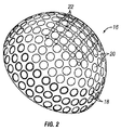
図2は、これより25−1と呼ばれ、異なるディンプルパターンを有するボール16の第2実施形態の1つの半球を示し、該実施形態は、各半球にボールの赤道の周りの3列の浅い台形ディンプル18と、ボールの極部分の深い球形ディンプル20とを有する。極に近い深いディンプルは、また、大型ディンプルの間に分散された小型ディンプル22を有する。図2の全体的なディンプルパターンは、図1のものと同様であるが、ディンプルの合計の数が少ない(386)。ボール16は、ボール10と同じ数の台形ディンプルを有するが、ボール10の球形ディンプルよりも少ない球形ディンプルを有し、その容積が小さい(下の表2参照)。ボール16の各半球は、92の台形ディンプルと、101の球形ディンプル20および22とを有する。パターン28−1とパターン25−1との間の主な違いは、28−1ディンプルパターンの深いディンプルの間の小型ディンプルの数および容積が25−1ディンプルパターンと比べて大きく、28−1ディンプルパターンの大きく深いディンプルも25−1の大型球形ディンプルパターンと比べて概して大きいので、図1の28−1ボールが極部分からより多くの重量が除去されていることである。ボール16の大型球形ディンプル20は、すべて、28−1ボールの最も小さい大型ディンプルの大きさと等しい同じサイズである。図2の台形ディンプルは、図1の台形ディンプルと同じサイズであり、台形ディンプルの半径は、大型球形ディンプル20と同じサイズである。
FIG. 2 shows one hemisphere of a second embodiment of a
表2に、図2の25−1ディンプルパターンを形成するための射出成形金型キャビティを形成するための、ディンプルの半径、深さおよびディンプルの位置情報を示す。 Table 2 shows the dimple radius, depth, and dimple position information for forming an injection mold cavity for forming the 25-1 dimple pattern of FIG.
表2に示すように、25−1ボールは、極部分に2つの異なるサイズの小型球形ディンプル22(28−1ボールのディンプル1および2と同じサイズのディンプル1および2)のみと、1サイズの大型球形ディンプル20、つまり、28−1ボールのディンプル5と同じ大きさのディンプル4のみとを有する。したがって、28−1ボールは、同じ球形ディンプル、具体的には、25−1ボールの球形ディンプル20のいずれよりも小さい径の、表1のディンプル6および7を有する。
As shown in Table 2, the 25-1 ball has only two different sized small spherical dimples 22 (
図3は、異なるディンプルパターンを有し、ディンプルパターンまたは2−9ディンプルパターンまたは2−9ボールとして特定される、ボールの第3実施形態を形成するようにデザインされた圧縮成形金型キャビティ24の一方の半球を有する金型23を示す。キャビティ24は、ボールの赤道の周囲に3列の浅い台形ディンプルを形成するためにデザインされた3列の盛り上がった扁平な隆起25と、ボールの極部分に深い球形ディンプルを形成するために極部分に盛り上がった概略半球状の隆起26とを有する。結果的なディンプルパターンは、ボールのそれぞれの半球に、ボールの赤道の周りの3列の浅い台形ディンプルと、ボールの極部分の深い球形ディンプル2とを有する。図3に図示し、下の表3に示すように、2−9ディンプルパターンには1つの大きさの台形ディンプルおよび1つの大きさの球形ディンプルのみが存在する。台形ディンプルは、下の表3においてディンプル#1で表され、球形ディンプルは、表3においてディンプル#2で表されている。2−9ボールは、28−1ボールおよび25−1ボールの台形ディンプルと同じ大きさの92の台形ディンプルと、25−1ボールの大型球形ディンプルと同じ大きさの76の深い球形ディンプルとを有する合計336のディンプルを有する。したがって、28−1ボール、25−1ボールおよび2−9ボールの赤道の周囲において、略同じディンプル容積が除去されているが、28−1ボールの極部分では、25−1ボールおよび2−9ボールにおけるものよりも大きなディンプル容積が除去されており、2−9ボールは、28−1ボールおよび25−1ボールよりも極部分において除去された容積が小さい。
FIG. 3 shows a
同様に金型または金型の組が、ここで説明するすべての実施形態に使用され、金型23は、例示の方法としてのみ示されることが理解されるであろう。
Similarly, it will be appreciated that a mold or set of molds is used in all embodiments described herein, and
下の表4は、28−1ディンプルパターンとよく似ているので別には図示しない、28−2ディンプルパターンのボールにおけるディンプルの形状、寸法、および、座標また配置を列挙する。28−1ディンプルパターンのボールは、表4の番号5,6および7の異なる寸法の3種類の大型球形ディンプルと、番号1,2および3の異なる寸法の3種類の小型球形ディンプルとを有し、これらのディンプルの寸法は、表4の番号4の台形ディンプルの寸法と同様に、表1の28−1ボールの対応するディンプルと同一である。28−2ディンプルパターンは、ボールの2つの半球を分割する継ぎ目が28−2ボールにおいて広く、ディンプルのいくつかの座標が表1と表4とを比較することによって定められるように僅かに異なることを除いて、28−1ディンプルパターンと略同一である。
Table 4 below lists the shape, dimensions, coordinates, and arrangement of dimples in a 28-2 dimple pattern ball that are not shown separately because they are very similar to the 28-1 dimple pattern. A ball having a 28-1 dimple pattern has three types of large spherical dimples having different sizes of
28−2パターンのディンプルの座標は、下の表4に示される。 The coordinates of the dimples of the 28-2 pattern are shown in Table 4 below.
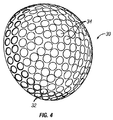
図4から6は、異なるディンプルパターンを有する3つの異なるボール30,40および50の半球を示す。ボール30,40および50のディンプルパターンは、これより、ディンプルパターン25−2,25−3および25−2と呼ぶ。25−2,25−3および25−2は、それぞれが有する赤道を取り囲む台形ディンプルの列の数が異なることを除いて基本的に同じデザインを有するとう関係にある。図4から6のディンプルの寸法および位置は、それぞれ、下の表5,6および7に与えられる。
4 to 6 show hemispheres of three
図4のボール30または25−2は、各半球の赤道に隣接する2列の(つまり、完成したボールにおいて合計4列の)浅い台形ディンプル32と、それぞれの極部分に球形ディンプル34とを有する。表5に示すように、2つの異なる大きさの球形ディンプル34および2つの異なる大きさの台形ディンプル32が存在する。
The
図5のボール40または25−3は、それぞれの赤道に隣接する4列の浅い台形ディンプル42(つまり、完成したボールにおいて赤道の周囲に合計4列の浅い台形のディンプル)と、それぞれの極部分に深い球形ディンプル44とを有する。図5に図示し、テーブル6に示すように、台形ディンプル42は、3つの異なる大きさのものであり、赤道から3列目および4列目(つまり、極部分に近い2列)のディンプル列にのみ配置された最大サイズのディンプル42Aを有する。ボール40は、また、表6に示すように、僅かに半径の異なる複数の球形ディンプルを有する。
The
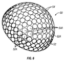
図6のボール50または25−4は、それぞれの赤道の両側に浅い台形ディンプル52(つまり、赤道周りの6列のディンプルの周囲帯域)と、それぞれの極部分に深い球形ディンプル54とを有する。ボール50は、表7に示すように、3つの異なる半径の球形ディンプルと、3つの異なる半径の台形ディンプルとを有する。図6に図示し下の表7に示すように、台形ディンプルの第3列、つまり、極部分に隣接する列は、いくつかの大型台形ディンプル52Aであって、表7においてディンプル#5として示された3つの最大の台形ディンプルを有する。隣接する極部分も、図6に示すように、大型台形ディンプルと概略三角形のパターンに配置された、いくつかの大型球形ディンプル54Aを有する。ディンプル54Aは、表7においてディンプル#6として示された3つの最大の球形ディンプルである。表7に示すように、すべてが0.0875インチの半径を有する合計12の大型台形ディンプル#5および合計12の大型球形ディンプル#6が存在する。図6は、3つの大型台形ディンプルと3つの大型球形ディンプルとの1箇所への配置を示す。図6に示したボールの半球の円周の残りに、等間隔の3箇所に、同様の配置が設けられている。
The
下の表5,6および7に示すように、ボール25−2および25−3は、それぞれ、赤道部分に3つの異なる大きさの台形ディンプルと、極部分に2つの異なる大きさの球形ディンプルとを有するが、ボール25−4は、3つの異なる大きさの台形ディンプルと、3つの異なる大きさの球形ディンプルとを有する。極部分のディンプルは、赤道部分に4列(半球に2列)の台形ディンプルを有するボール25−2において最大であり、赤道部分に4列の台形ディンプルを有するボール25−3において最小である。代案の実施形態において、ボールは、各半球に1列の台形ディンプルを有し、球表面が赤道部分、赤道周りの2列または4列以上のディンプルと等しい幅を有する球表面または帯域においてディンプルを有しないように、或いは、赤道の周囲に位置するディンプルのない球表面領域と交互に位置するディンプルのある部分を有するように、形成されてもよい。 As shown in Tables 5, 6 and 7 below, the balls 25-2 and 25-3 each have three different sized trapezoidal dimples in the equator portion and two different sized spherical dimples in the pole portion. However, the ball 25-4 has trapezoidal dimples of three different sizes and spherical dimples of three different sizes. The polar portion dimples are the largest in the ball 25-2 having four rows of trapezoidal dimples in the equator portion (two rows in the hemisphere) and the smallest in the ball 25-3 having four rows of trapezoidal dimples in the equator portion. In an alternative embodiment, the ball has one row of trapezoidal dimples in each hemisphere, and the sphere surface has dimples at the equator portion, a sphere surface or zone having a width equal to two or more rows of dimples around the equator. It may be formed so as not to have, or to have a portion with dimples alternately positioned with a spherical surface region without dimples located around the equator.
ディンプルパターン25−2,25−3および24−4は、赤道部分の周囲の台形ディンプルと極部分の周囲の深いディンプルとを有する点でパターン2−9と同様であるが、ディンプルパターン25−2,25−3および24−4における台形ディンプルは、パターン28−1,25−1および2−9の台形ディンプルよりも径が大きい。赤道の近くの大型台形ディンプルは、赤道部分から重量をより多く除去することを意味する。他のすべての要因が同じであれば、これは、ボール25−2,25−3および25−4が、ボール28−1,28−2,25−1および2−9よりも、PH配向とPOP配向との間のMOIの差が小さいことを意味する。 The dimple patterns 25-2, 25-3 and 24-4 are similar to the pattern 2-9 in that they have a trapezoidal dimple around the equator portion and a deep dimple around the pole portion, but the dimple pattern 25-2. 25-3 and 24-4 have larger trapezoidal dimples than the trapezoidal dimples of patterns 28-1, 25-1 and 2-9. Large trapezoidal dimples near the equator mean that more weight is removed from the equator. If all other factors are the same, this means that the balls 25-2, 25-3 and 25-4 are more PH oriented than the balls 28-1, 28-2, 25-1 and 2-9. This means that the MOI difference from the POP orientation is small.
図7は、以下の説明においてディンプルパターン28−3として特定される異なるディンプルパターンを有する他の実施形態に係るゴルフボール60の一方の半球を示す。ボール60のディンプルパターン28−3は、赤道の両側に台形ディンプル62の3つの列と、両極に小型球形ディンプル64の領域と、ディンプル64とディンプル62との間の大型で深い球形ディンプル65の領域とを含む。表8は、ゴルフボール60のディンプルのパラメータおよび座標を示す。表8に示すように、ボール38−3は、1つの大きさの台形ディンプルと、4つの大きさの大型球形ディンプル(ディンプル番号2,3,5および6)と、極部分の1つの大きさの小型球形ディンプル(ディンプル番号1)とを有する。
FIG. 7 shows one hemisphere of a
表8および図7に示すように、極の小型球形ディンプル64は、すべて同じ半径であり、13のディンプル64が、各半球の極に中心を合わせた概略正方形パターンに配置されている。0.075インチから0.0825インチまで半径が徐々に増加する4つの異なる大型球形ディンプル65(表8のディンプル番号2から6)がある。また、ディンプルパターン28−3のボールは、各極部分に赤道の周りの赤道帯域よりもディンプルの大きい容積を配置したことで生じた重量の差によって、両極を通る優先軸スピン軸を有する。
As shown in Table 8 and FIG. 7, the small
28−3ボールの1つの半球を形成するためのディンプルのパターンおよび座標は、下の表8に列挙される。 The dimple patterns and coordinates to form one hemisphere of a 28-3 ball are listed in Table 8 below.
1つの実施形態において、ボール28−1,28−2および28−3の継ぎ目幅は、合計0.0088インチ(各半球に振り分け)であったが、ボール25−2,25−3および25−4の継ぎ目幅は、0.006インチであり、ボール25−1の継ぎ目幅は、0.030インチであった。 In one embodiment, the ball 28-1, 28-2 and 28-3 had a total seam width of 0.0088 inches (allocated to each hemisphere), but balls 25-2, 25-3 and 25- The seam width of No. 4 was 0.006 inches, and the seam width of Ball 25-1 was 0.030 inches.
上述し、図1から7に示したそれぞれのディンプルパターンは、赤道の周りの帯域において小さいディンプル容積を有し、極部分において大きいディンプル容積を有する。これらのディンプルパターンを有するボールは、両極を通って延伸する優先スピン軸を有し、ボールがティーの上に優先スピン軸が実質的に水平になるように配置されたならばスライスおよびフックに抵抗する。ティーの上に優先スピン軸が上下を指すように(POP配向)配置されたなら、ボールは、PH配向に配置されたときと比較して、フックおよびスライスを矯正する作用が小さい。必要であれば、ボールは、ティーの上に優先スピン軸が約45°だけ右に傾斜して配向されてもよく、この場合、ボールは、やはりスライスの曲がりを低減するが、フックの曲がりはあまり低減しない。優先スピン軸が左に約45°傾斜していれば、ボールはフックの曲がりを低減するが、スライスの曲がりにはあまり抵抗しない。 Each of the dimple patterns described above and shown in FIGS. 1 to 7 has a small dimple volume in the band around the equator and a large dimple volume in the pole portion. Balls with these dimple patterns have a preferential spin axis that extends through both poles and resists slicing and hooking if the ball is placed on the tee so that the preferential spin axis is substantially horizontal To do. If the preferential spin axis is positioned above and below the tee (POP orientation), the ball has less effect of correcting hooks and slices than when placed in the PH orientation. If necessary, the ball may be oriented on the tee with the preferred spin axis tilted to the right by about 45 °, in which case the ball will also reduce slice bending, but not hook bending. Does not reduce much. If the preferred spin axis is tilted approximately 45 ° to the left, the ball reduces hook bending but does not resist slice bending very much.
図8は、図1のボール28−1と同様のディンプルパターンを有するが、赤道の周囲にディンプルのない広い領域または球面領域72を有するボール70を示す。図8の実施形態において、部分72は、図1のボール10から赤道の両側のそれぞれ2列のディンプルを取り除き、1列の浅い台形ディンプル74を残すことによって形成される。極部分のディンプルは、図1に示され、同じ参照番号が同じディンプルに使用されている。台形ディンプルの列は、赤道の周りのディンプルのない領域または表面領域を残すような同様の方法で、図2から7のいずれのボールから取り除かれてもよい。ある実施形態におけるディンプルのない領域は、幅広の継ぎ目のように狭くてもよく、或いは、赤道に隣接する円台形ディンプルの列の1列、2列またはすべてを取り除くことによって拡げられ、極水平(PH)配向と他の配向との間のMOIの大きな差を生成するようにしてもよい。
FIG. 8 shows a ball 70 having a dimple pattern similar to the ball 28-1 of FIG. 1, but having a wide or
図9は、上述のゴルフボールのディンプルパターンに用いられる台形ディンプルと球形ディンプルとの間の弦深さの関係を示す図である。約1.68インチの直径を有するゴルフボールは、高分子の収縮に適応するために内径約1.694インチの金型を使用して成型された。図9は、d2の球形弦深さ、および、破線の長さの半分として表される半径Rの球形ディンプル76を有する、ゴルフボールの表面75の一部を示す。台形ディンプルを形成するために、A−A平面に沿って切断がなされて、浅いディンプルが形成される。台形ディンプルは、球形弦深さd2よりも小さい台形弦深さd1を有する。ディンプルのエッジより上の取り除かれた被覆材の容積は、深さd3の破線上の容積V3によって表される。
V1=台形ディンプルの容積であり、
V1+V2=球形ディンプルの容積であり、
V1+V2+V3=球形ディンプルを形成するために取り除かれる被覆材の容積であり、そして、
V1+V3=台形ディンプルを形成するために取り除かれる被覆材の容積である。
同じ半径および球形弦深さに基づくディンプルのために、台形ディンプルを有するボールと円形ディンプルを有するボールとの間の慣性モーメントの差は、球形ディンプルの形成において除去され、台形ディンプルの形成において除去されない、線または平面A−Aの下の容積V2に関係する。ボールの一方が台形ディンプルのみを有し、他方が球形ディンプルのみを有し、他の要素が同じであり、他のすべての要素が同じであるボール台形ディンプルと球形ディンプルとの差が容積V2のみである(つまり他のディンプルのパラメータが同じ)場合、台形ディンプルを有するボールは、ディンプルを形成するために上面からより多くの材料が除去された球形ディンプルを有するボールよりも、重量が大きく、高いMOIを有する。
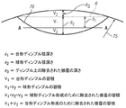
FIG. 9 is a diagram showing the relationship of the chord depth between the trapezoidal dimple and the spherical dimple used in the above-described golf ball dimple pattern. A golf ball having a diameter of about 1.68 inches was molded using a mold with an inner diameter of about 1.694 inches to accommodate polymer shrinkage. FIG. 9 shows a portion of a
V1 = the volume of the trapezoidal dimple,
V1 + V2 = the volume of the spherical dimple,
V1 + V2 + V3 = the volume of dressing removed to form a spherical dimple, and
V1 + V3 = Volume volume removed to form trapezoidal dimples.
Because of dimples based on the same radius and spherical chord depth, the difference in moment of inertia between balls with trapezoidal dimples and balls with circular dimples is eliminated in the formation of spherical dimples and not in the formation of trapezoidal dimples. , Relating to the volume V2 below the line or plane AA. One of the balls has only a trapezoidal dimple, the other has only a spherical dimple, the other elements are the same, and the difference between the ball trapezoidal dimple and the spherical dimple where all other elements are the same is the volume V2 only (Ie, the parameters of other dimples are the same), a ball with trapezoidal dimples is heavier and higher than a ball with spherical dimples where more material has been removed from the top surface to form the dimples Has MOI.
適切な慣性モーメントは、図1から7および表1から8に示したボール(つまり、ボール2−9,25−1から25−4および28−1から28−3)のそれぞれのために計算できる。1つの実施形態において、これらのパラメータを有するボールは、SolidWorks(商標)によって図面化され、そして、それらのMOIが、公知のポララ(Pplara:商標)ゴルフボールを基準として参照して算出された。SolidWorks(商標)は、0.036413lbs/in^3(ポンド/立方インチ)の均一なソリッド密度を有するボールに基づいてMOIを計算するために使用された。各ボールの他の物理的大きさおよび重さのパラメータは、下の表9に与えられる。 Appropriate moments of inertia can be calculated for each of the balls shown in FIGS. 1-7 and Tables 1-8 (ie, balls 2-9, 25-1 to 25-4 and 28-1 to 28-3), respectively. . In one embodiment, balls having these parameters were charted by SolidWorks ™ and their MOIs were calculated with reference to known Plara ™ golf balls. SolidWorks ™ was used to calculate the MOI based on balls with a uniform solid density of 0.036413 lbs / in 3 (pounds / cubic inch). Other physical size and weight parameters for each ball are given in Table 9 below.
基準であるポララ(Polara:商標)ゴルフボールを用い、各配向の間のMOIの差が、互いに比較されるだけでなく、ポララゴルフボールとも比較された。2つの配向の間の最大の差を、図10では「MOIΔ」と呼ぶ。MOIΔの右の2列は、2つの配向の間のMOIの最大の%差、および、ポララボールのMOIΔに対するMOIΔとして、MOIΔを定量化する。質量およびMOIの計算に使用した密度の値は、ゴルフボールの平均密度よりも小さいので、予測される各ボールの重さおよびMOIは、相対的なものであって、製造し、ロボットで試験し、表10に示したゴルフボールの実際のMOIΔの値と厳密に同じではない。一般に、ゴルフボールの重さは約45.5g−45.9gである。表10のすべてのボールのMOIの値の比較は、最小のMOIの差を有する25−3ボールおよび最大のMOIの差を有する28−2ボールを含む異なるデザインの間のMOIの差の相対的な順位を予測する点において非常に有益である。 Using the reference Polara ™ golf ball, the MOI difference between each orientation was compared not only to each other, but also to the polara golf ball. The maximum difference between the two orientations is referred to as “MOIΔ” in FIG. The two right columns of MOIΔ quantify MOIΔ as the maximum% difference in MOI between the two orientations and the MOIΔ relative to the MOIΔ of the polara ball. Since the density values used to calculate the mass and MOI are less than the average density of the golf ball, the expected weight and MOI of each ball is relative and is manufactured and tested with a robot. These are not exactly the same as the actual MOIΔ values of the golf balls shown in Table 10. Generally, a golf ball weighs about 45.5g-45.9g. A comparison of the MOI values for all balls in Table 10 shows the relative MOI differences between the different designs including 25-3 balls with the smallest MOI difference and 28-2 balls with the largest MOI difference. This is very useful in predicting the correct ranking.
表11は、ボールのMOIΔがボールの曲がりのコントロールに強く影響することを示す。一般に、各ボールの相対MOIΔが増加すると、スライスショットのまがり距離が減少する。表11に示した結果は、公知のトップフライトXLストレートボールの試験から得られたデータ、および、後で詳細に検討するような標準実験室条件の下でのロボット試験の間に得られるデータも含む。 Table 11 shows that the MOIΔ of the ball strongly affects the control of the bending of the ball. In general, as the relative MOI Δ of each ball increases, the rolling distance of the slice shot decreases. The results shown in Table 11 also include data obtained from testing of a known top flight XL straight ball and data obtained during robot testing under standard laboratory conditions as discussed in detail later. Including.
表11に示すように、ボール28−3,25−1,28−1および28−2は、すべて、ポララに比べて高いMOIΔを有し、それらのすべては、ポララよりも高い曲がりコントロール性を有する。このMOIの差は、キャロウェイゴルフによって製造されたトップフライトXLストレートの試験データも含む図10および11にも示されている。 As shown in Table 11, the balls 28-3, 25-1, 28-1 and 28-2 all have a higher MOIΔ than the polara, and all of them have a higher bending controllability than the polara. Have. This MOI difference is also shown in FIGS. 10 and 11, which also include test data for a top flight XL straight manufactured by Callaway Golf.
飛翔中のゴルフボールに作用する空気力学的力は、3つの力のベクトル:揚力、抗力および重力に分解できる。揚力ベクトルは、製品のスピンおよび速度ベクトルに交差する方向に作用する。抗力ベクトルは、速度ベクトルと反対方向に作用する。より具体的には、ゴルフボールの空気力学的特性は、レイノルズ数(Re)と無次元スピンパラメータ(DSP)の関数である揚力係数および抗力係数によって特徴付けられる。レイノルズ数は、空気中を飛行するゴルフボールに作用する慣性の粘性力に対する比を定量化する無次元量である。無次元スピンパラメータは、ゴルフボールの表面回転速度と空気中の速度との比である。 Aerodynamic forces acting on a flying golf ball can be broken down into three force vectors: lift, drag and gravity. The lift vector acts in a direction that intersects the product spin and velocity vectors. The drag vector acts in the opposite direction to the velocity vector. More specifically, the aerodynamic characteristics of a golf ball are characterized by lift and drag coefficients that are functions of Reynolds number (Re) and dimensionless spin parameters (DSP). The Reynolds number is a dimensionless quantity that quantifies the ratio of inertia to viscous force acting on a golf ball flying in the air. The dimensionless spin parameter is the ratio of the surface rotation speed of the golf ball to the speed in the air.
ゴルフボールの揚力係数および抗力係数は、ニュージャージー州ファーヒルズのUSGAテストセンターのもののような室内テストレンジおよびデンマークのインタラクティブスポーツグループによって造られたトラックマンネットシステム(Trackman Net System)のような屋外システムを含む、いくつかの異なる方法を用いて測定できる。上述の実施形態および比較のためにいくつかの従来のゴルフボールについてトラックマンネットシステムを使用して得られた試験結果を、以下に説明し、図10から17に示す。 The lift and drag coefficients of a golf ball are measured using indoor test ranges such as those at the USGA Test Center in Far Hills, New Jersey and outdoor systems such as the Trackman Net System created by the Danish Interactive Sports Group. It can be measured using a number of different methods, including: Test results obtained using the Trackman Net system for several conventional golf balls for the above-described embodiments and comparison are described below and shown in FIGS.
右打ちのゴルファー、特にハンディキャップの高いゴルファーにとって、大きな問題は、ボールの「スライス」傾向である。意図しないスライスショットは、2つの意味でゴルファーに不利益である:1)ボールが意図した飛翔経路から右に逸れる、2)ショット飛距離全体を低減する。スライスしたゴルフボールは、ボールのスピン軸が右に傾いているので右に移動する。揚力は、定義上、スピン軸に直角であり、そのため、スライスしたゴルフボールの揚力は、右を向いている。 For right-handed golfers, especially those with high handicaps, a major problem is the “slicing” tendency of the ball. Unintentional slice shots are detrimental to the golfer in two ways: 1) The ball deviates to the right from the intended flight path 2) Reduces the overall shot distance. The sliced golf ball moves to the right because the spin axis of the ball is tilted to the right. Lift is by definition perpendicular to the spin axis, so the lift of a sliced golf ball is pointing to the right.
ゴルフボールのスピン軸は、ボールがその周りに回転する軸であり、通常、ゴルフボールが飛翔する方向に直角である。ゴルフボールのスピン軸が0°、つまり、純粋なバックスピンをも生じる水平スピン軸であれば、ボールはフックまたはスライスせず、0°のスピン軸と組み合わさった高い揚力は、ボールを高く飛翔させるだけである。しかしながら、ボールが0°以上のスピン軸を与えられるような方法で打たれたとき、ボールは、フックし、ボールは、0°未満のスピン軸ではスライスする。スピン軸の傾斜は、揚力を左または右の方向に向かわせ、ボールのフックまたはスライスを引き起こす。ボールの右または左への意図しない飛翔は、キャリー曲がりと呼ばれる。低く飛ぶゴルフボール、つまり、揚力の低いボールは、キャリー曲がりが小さいボールの強い指標である。 The spin axis of a golf ball is an axis around which the ball rotates, and is usually perpendicular to the direction in which the golf ball flies. If the spin axis of the golf ball is 0 °, that is, a horizontal spin axis that also produces pure backspin, the ball will not hook or slice, and the high lift combined with the 0 ° spin axis will fly the ball high. Just let it. However, when the ball is struck in a way that gives it a spin axis greater than 0 °, the ball hooks and the ball slices at a spin axis less than 0 °. The tilt of the spin axis directs lift in the left or right direction, causing a hook or slice of the ball. Unintentional flight of the ball to the right or left is called a carry curve. A golf ball that flies low, that is, a ball with low lift, is a strong indicator of a ball with a small carry curve.
フックまたはスライス方向に作用する揚力の大きさは、揚力×sin(スピン軸角度)に等しい。高さ方向に作用する揚力の大きさは、揚力×cos(スピン軸角度)である。 The magnitude of the lift acting in the hook or slice direction is equal to lift x sin (spin axis angle). The magnitude of the lift acting in the height direction is lift x cos (spin axis angle).
スライスショットの共通原因は、開いたクラブフェースでボールを打つことである。この場合、クラブフェースの開きは、クラブの実効ロフトを増大し、それにより、ボールの合計スピン量を増大する。他のすべての要因を一定に保つと、大きなボールスピン量は、一般に高い揚力を生成し、これが、スライスショットがしばしばストレートショットまたはフックショットよりも高い軌道を有する理由である。 A common cause of slice shots is hitting the ball with an open club face. In this case, the opening of the club face increases the effective loft of the club, thereby increasing the total spin amount of the ball. Keeping all other factors constant, a large amount of ball spin generally produces a higher lift, which is why slice shots often have a higher trajectory than straight or hook shots.
下の表は、約85−105mphの範囲のヘッドスピードを有するゴルファーにより、10.5°のドライバーを使用し、様々な試作ゴルフボールおよび低スピンおよび通常スピンのゴルフボールと考えられる市販のゴルフボールを打った際の、合計ボールスピン量を示す。
図10は、それぞれのデザインについて上述のトラックマンシステムを使用したロボット試験から得られたデータを使用した、最小配向と最大配向と(USGA規則の下で公認または対称ボールであるトップフライトXLはランダム配向)の間のMOIの差の変化に対する平均キャリー曲がりおよび合計曲がりを示す。図10の(および図4から6に示した)ボール25−2,25−3および25−4は、ボール25−2は両側に2列、ボール25−3は4列、ボール25−4は3列と、それぞれ赤道を取り囲むディンプルの列の数が異なることを除いて基本的に同じディンプルパターンを有するので、それらは関連する。図10のデータから得られるボールのそれぞれの最小配向と最大配向との間の%MOIΔは、下の表12に示されている。 FIG. 10 shows the minimum and maximum orientations using the data obtained from the robot test using the Trackman system described above for each design (top flight XL, which is a recognized or symmetric ball under USGA rules, is random The mean carry and total bends for the change in MOI difference between the (orientation). Balls 25-2, 25-3, and 25-4 in FIG. 10 (and shown in FIGS. 4 to 6), ball 25-2 has two rows on both sides, ball 25-3 has four rows, ball 25-4 has They are related because they have basically the same dimple pattern except that the three rows and the number of rows of dimples each surrounding the equator are different. The% MOIΔ between the respective minimum and maximum orientations of the balls obtained from the data of FIG. 10 is shown in Table 12 below.
図11は、それぞれのディンプルデザインの最小配向と最大配向との間のMOIの差に対する平均キャリーおよび合計飛距離を示す。 FIG. 11 shows the average carry and total flight distance for the MOI difference between the minimum and maximum orientations of each dimple design.
下の表13は、ボール25−1,28−1および2−9およびタイトリストProV1およびトップフライトXLストレートボールのスライス試験の結果を示す。ボール25−1,28−1および2−9は、PH配向およびPOP配向の両方について試験した。この表には、キャリー曲がり、キャリー飛距離、合計曲がり、合計飛距離および転がり距離の平均値が示されている。これは、ボール25−1,28−1および2−9が、PH配向においてPOP配向よりも著しく曲がりが小さく、試験した公知の対称ボールであるProV1およびトップフライトよりも曲がりが小さいことを示す。 Table 13 below shows the results of slicing tests on balls 25-1, 28-1 and 2-9 and Titleist ProV1 and top flight XL straight balls. Balls 25-1, 28-1 and 2-9 were tested for both PH and POP orientation. This table shows the average value of carry curve, carry flight distance, total curve, total flight distance and rolling distance. This indicates that the balls 25-1, 28-1, and 2-9 are significantly less bent in the PH orientation than the POP orientation and less than the known symmetric balls ProV1 and top flight tested.
ゴルフボール25−1,28−1,2−9、ポララ2p4/08、タイトリストProV1およびトップフライトXLストレートは、工業規格の実験室条件下でのいくつかの試験を受けて、ここに記載したディンプルパターンが取得した競合するゴルフボールと比べてよりよい性能を実証する。これらの試験において、ゴルフボール25−1,28−1,2−9の飛翔特性および距離特性を試験して、アクシネット(Acushnet)製タイトリストProV1、キャロウェイゴルフ製トップフライトXLストレート、および、パウンススポーツ社(Pounce Sport LLC)製ポララ2p4/08と比較した。また、ゴルフボール25−1,28−1,2−9、ポララ2p4/08は、極前後(PFB)配向、極上下(POP)配向および極水平(PH)配向にして試験した。ProV1およびトップフライトXLストレートは、USGA公認球であり、そのため、球対称であると知られているため、そのような特定の配向では試験していない(ランダム配向)。ゴルフボール25−1および28−1は、基本的に同じ材料で形成され、デュポン製HPF2000を主とするコアとサーリン(Surlyn:商標)を混合(9150を50%、8150を50%)した被覆とからなる。被覆は、約0.06インチの厚みである。 Golf Balls 25-1, 28-1, 2-9, Polara 2p4 / 08, Titleist ProV1 and Topflight XL Straight have undergone several tests under industry standard laboratory conditions and have the dimples described herein The pattern demonstrates better performance compared to competing golf balls acquired. In these tests, the flight characteristics and distance characteristics of the golf balls 25-1, 28-1, and 2-9 were tested, and the Titleist ProV1 manufactured by Acushnet, the top flight XL straight manufactured by Callaway Golf, and the pounce sport. It was compared with Polara 2p4 / 08 manufactured by Ponce Sport LLC. In addition, golf balls 25-1, 28-1, 2-9, and Polara 2p4 / 08 were tested in a polar front / rear (PFB) orientation, a polar top / bottom (POP) orientation, and a polar horizontal (PH) orientation. ProV1 and Topflight XL straight are USGA certified spheres, and are therefore not known to be spherically symmetric and have not been tested in such specific orientations (random orientation). The golf balls 25-1 and 28-1 are basically made of the same material and have a core made mainly of DuPont HPF2000 and a mixture of Surlyn (Surlyn ™) (9150 50%, 8150 50%). It consists of. The coating is approximately 0.06 inches thick.
試験は、ゴルフラボラトリーズ社製ロボットを用い、同一のテーラーメイド(Taylor Made:商標)のドライバーを使用して異なるクラブヘッド速度で行った。テーラーメードドライバーは、10.5°のR9 460クラブヘッドとモトーレ(Motore)65”S”シャフトを有する。ゴルフボールは、無作為の順番で打たれた。さらに、ボールは、約15−25°のスライスをシミュレートする条件、例えば15−25°のネガティブスピンで試験された。
The tests were conducted at different club head speeds using a Golf Laboratories robot using the same Taylor Made ™ driver. The tailor-made driver has a 10.5 ° R9 460 club head and a
図12および13は、上記試験時のトラックマンネットシステムによる個別のショットの軌道の平面図および側面図の例である。図12および13のトラックマン軌道データは、PH配向のボール28−1,25−1および2−9がより真っ直ぐで(曲がりが少なく)、低く飛んでいる(低い軌道高さ)ことをはっきりと示す。図13における最大高さデータは、各ゴルフボールによって生成される揚力係数(CL)と直接相互に関係する。この結果は、ProV1およびトップフライトXLストレートが、PH配向の28−1,25−1または2−9ボールよりも大きな揚力を生成したことを示す。 12 and 13 are examples of a plan view and a side view of the trajectory of individual shots by the track mannet system during the test. The Trackman trajectory data of FIGS. 12 and 13 clearly show that the PH oriented balls 28-1, 25-1 and 2-9 are more straight (less curved) and fly lower (lower trajectory height). Show. The maximum height data in FIG. 13 correlates directly with the lift coefficient (CL) generated by each golf ball. This result indicates that ProV1 and Top Flight XL straight produced greater lift than PH-oriented 28-1, 25-1, or 2-9 balls.
[揚力係数および抗力係数試験および結果、CLおよびCD回帰]
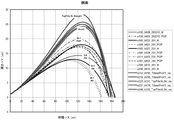
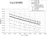
図14−17は、25−1,28−1および2−9ディンプルデザイン並びにトップフライトXLストレート、ポララ2pおよびタイトリストProV1のスピン量3500rpmおよび4500rpmのそれぞれにおけるレイノルズ数(Re)に対する揚力係数および抗力係数(CLおよびCD)を示す。各グラフの曲線は、特定の配向における各ボールデザインの複数のストレートショットの回帰分析から生成された。
[Lift coefficient and drag coefficient tests and results, CL and CD regression]
FIGS. 14-17 show lift coefficients and drag coefficients for Reynolds numbers (Re) at spin rates of 3500 rpm and 4500 rpm respectively for 25-1, 28-1 and 2-9 dimple designs and top flight XL straight,
図14−17の曲線は、2010年1月から4月までの期間に行われた試験の間の、多様なスピンおよびレイノルズ数の条件における多くのショットの回帰分析の結果を示す。図14から17の回帰データを得るために、3つのレーダユニットからなるトラックマンネットシステムが使用されて、多様なゴルフクラブを使用したゴルフラボロボットにより打たれたゴルフボールの軌道を追跡した。ロボットは、多様な初期スピン量および速度のストレートショットを打つように設定された。風速計が、ロボットの位置の近くの20フィートの高さの風速を計測するために使用された。トラックマンネットシステムは、軌道データ(時間に対するx,y,z位置)を測定した。軌道データは、レイノルズ数、ボールスピン量および無次元スピンパラメータを含む計測した経時変化する量の関数として揚力係数(CL)および抗力係数(CD)を計算するために使用される。それぞれのゴルフボールモのデルまたはデザインは、スピン量3000−5000rpmおよびレイノルズ数120000−18000を含む速度およびスピンの条件範囲において試験された。そして、レイノルズ数(Re)および無次元スピン量(W)の関数である揚力係数および抗力係数の5項多変量回帰モデルは、各ボールデザインのデータに合わせた。CLおよびCDの回帰方程式は、
CLRegression=a1×Re+a2×W+a3×Re2+a4×W2+a5×ReW+a6
CDRegression=b1×Re+b2×W+b3×Re2+b4×W2+b5×ReW+b6
ここで、ai(i=1−6)は、揚力係数のための回帰係数であり、bi(i=1−6)は、抗力係数のための回帰係数である。
The curves in FIGS. 14-17 show the results of regression analysis of a number of shots at various spin and Reynolds number conditions during the tests conducted during the period January to April 2010. In order to obtain the regression data of FIGS. 14 to 17, a trackman net system consisting of three radar units was used to track the trajectory of a golf ball hit by a golf lab robot using various golf clubs. The robot was set to hit straight shots with various initial spin rates and velocities. An anemometer was used to measure the 20 feet high wind speed near the position of the robot. The Trackman net system measured trajectory data (x, y, z position with respect to time). Orbital data is used to calculate lift coefficient (CL) and drag coefficient (CD) as a function of measured time-varying quantities including Reynolds number, ball spin rate and dimensionless spin parameters. Each golf ball model or design was tested in a range of speed and spin conditions including a spin rate of 3000-5000 rpm and a Reynolds number of 120,000-18000. A 5-term multivariate regression model of lift coefficient and drag coefficient, which is a function of Reynolds number (Re) and dimensionless spin rate (W), was adjusted to the data of each ball design. The regression equations for CL and CD are
CL Regression = a 1 × Re + a 2 × W + a 3 × Re 2 + a 4 × W 2 + a 5 × ReW + a 6
CD Regression = b 1 × Re + b 2 × W + b 3 × Re 2 + b 4 × W 2 + b 5 × ReW + b 6
Here, a i (i = 1-6) is a regression coefficient for the lift coefficient, and b i (i = 1-6) is a regression coefficient for the drag coefficient.
通常、測定したReおよびWの範囲内で予測(補間)されたCDおよびCLの値は、実測したCDおよびCLの値と略一致した。標準的な相関係数は96−98%である。 Usually, the values of CD and CL predicted (interpolated) within the measured range of Re and W almost coincided with the measured values of CD and CL. The standard correlation coefficient is 96-98%.
下の表14Aおよび14Bは、図14−17に示したそれぞれのボールのための回帰定数である。これらの回帰定数を使用して、スピン量が3000−5000rpmでレイノルズ数が120000−180000の範囲で抗力係数および揚力係数を算出できる。図14から17は、スピンおよびReの条件の非常に限定された(3500または4500rpmでReが120000から180000まで変化する)設定で構成されており、表14Aおよび14Bに示す揚力および抗力のための補間定数に含まれるデータの膨大な値の少しの例を単に提供する。定数は、3000−5000rpmのスピン量、且つ、120000−180000のレイノルズ数の範囲内の如何なる点の揚力係数および抗力係数を示すためにも使用できる。 Tables 14A and 14B below are the regression constants for each ball shown in FIGS. 14-17. Using these regression constants, the drag coefficient and the lift coefficient can be calculated in the range where the spin rate is 3000-5000 rpm and the Reynolds number is 120,000-180000. Figures 14 to 17 consist of very limited settings of spin and Re conditions (Re varies from 120,000 to 180000 at 3500 or 4500 rpm) for the lift and drag shown in Tables 14A and 14B. It just provides a few examples of the vast values of the data contained in the interpolation constants. The constant can be used to indicate the lift and drag coefficients at any point within the range of spin rates of 3000-5000 rpm and Reynolds numbers of 120,000-180000.
図14から17から定められるように、極水平(PH)配向のボール25−1,28−1および2−9の揚力係数は、レイノルズ数(Re)が18000且つスピン量3500rpmにおいて0.10から0.14の間であって、レイノルズ数(Re)12000且つスピン量3500rpmにおいて0.14から0.20の間であり、試験した他の3つのボール(PHおよびPFBのポララ2p4/08、ランダム配向のタイトリストProV1およびトップフライトXLストレート)のCLよりも小さい。PH配向のボール25−1,28−1および2−9のスピン量4500rpmにおける揚力係数またはCLは、図15に示すように、Re180000において0.13から0.16の間であり、Re120000において0.17から0.25の間である。PH配向のボール25−1,28−1および2−9のスピン量3500rpmにおける抗力係数(CD)は、図16に示すように、Re150000において0.23から0.26の間であり、Re120000において0.24から0.27の間である。同じボールのスピン量4500rpmにおけるCD(図17)は、Re120000において0.28から0.29の間であり、Re180000において0.23から0.26の間である。 As determined from FIGS. 14 to 17, the lift coefficients of extremely horizontal (PH) oriented balls 25-1, 28-1 and 2-9 are from 0.10 at a Reynolds number (Re) of 18000 and a spin rate of 3500 rpm. Between 0.14 and Reynolds number (Re) 12000 and spin rate 3500 rpm between 0.14 and 0.20, the other three balls tested (PH and PFB Polar 2p4 / 08, random It is smaller than CL of the orientation Titleist ProV1 and the top flight XL straight). The lift coefficient or CL of the PH-oriented balls 25-1, 28-1, and 2-9 at a spin rate of 4500 rpm is between 0.13 and 0.16 at Re180000 and 0 at Re120,000 as shown in FIG. .Between 17 and 0.25. The drag coefficient (CD) of the PH-oriented balls 25-1, 28-1, and 2-9 at a spin rate of 3500 rpm is between 0.23 and 0.26 at Re150,000, as shown in FIG. It is between 0.24 and 0.27. The CD of the same ball at a spin rate of 4500 rpm (FIG. 17) is between 0.28 and 0.29 at Re120,000 and between 0.23 and 0.26 at Re18000.
スピン量3000rpm以上の典型的なスライス条件では、PH配向のボール2−9,25−1,28−1およびPFB配向のポララ2pは、市販のボール:ProV1およびトップフライトXLストレートよりも低い揚力係数を示す。低い揚力係数は、ストレートショットでの低い軌道と、スライスショットでの小さい曲がりを意味する。PH配向のディンプルパターン2−9,25−1,28−1のボールは、スライスショットの特徴的Reおよびスピンの条件下において、ProV1およびトップフライトXLストレートよりも約40%低い揚力係数を有する。
Under typical slicing conditions with a spin rate of 3000 rpm and higher, PH oriented balls 2-9, 25-1, 28-1 and PFB oriented
表15−17は、ロボットテストのトラックマンレポートである。ロボットは、約7°のアウトサイド−インのクラブ軌道で、僅かにクラブフェースを開いたスライスショットを打つように設定された。クラブ速度は約98−100mphであり、ボールの構造に応じて約3800−5200rpmの初期ボールスピンで、スピン軸は約13−21°であった。 Tables 15-17 are the robot test track man reports. The robot was set to hit a slice shot with a slightly open club face with an outside-in club trajectory of about 7 °. The club speed was about 98-100 mph, with an initial ball spin of about 3800-5200 rpm, depending on the ball structure, and the spin axis was about 13-21 °.
少なくとも赤道の周りの部分に沿ったディンプル容積が小さい領域と、極部分のディンプル容積が大きい領域とを含むディンプルパターンを有する上述の非公認ゴルフボールは、極水平配向または最大の配向と他の配向との間に十分に大きい慣性モーメント(MOI)の差を有し、ボールが両極を通って延伸する優先スピン軸を有する。上述のように、この優先スピン軸は、従来の対称デザインのゴルフボールにおいて、通常はフックまたはスライスするような方法でボールを打ったときに、フックまたはスライスの曲がりを防止またはその量を低減することを助ける。この曲がりの低減は、図10の上記実施形態および図12の実施形態のいくつかについて示されている。優先スピン軸は、代案として、ゴルフボールのコアまたは中間層の中の特定の位置の比重の大きい材料および比重の小さい材料によって達成されてもよいが、そのような構造は、ゴルフボール製造プロセスの費用と複雑さと追加する。これに対し、上述の異なるディンプルパターンを有するボールは、例えば2−9ボールについて図3に示すように、半球状の金型キャビティの適切なデザインによって容易に製造できる。 The above-mentioned non-official golf ball having a dimple pattern including at least a region having a small dimple volume along a portion around the equator and a region having a large dimple volume at the pole portion has a polar horizontal orientation or a maximum orientation and other orientations. With a sufficiently large moment of inertia (MOI) difference and the ball has a preferred spin axis that extends through both poles. As noted above, this preferred spin axis prevents or reduces the amount of hook or slice bending in conventional symmetrically designed golf balls when the ball is struck in a manner that is usually hooked or sliced. To help. This reduction in bending is illustrated for the above embodiment of FIG. 10 and some of the embodiments of FIG. The preferred spin axis may alternatively be achieved by a high specific gravity material and a low specific gravity material at a specific location in the core or intermediate layer of the golf ball, but such a structure is Add cost and complexity. On the other hand, balls having different dimple patterns as described above can be easily manufactured by appropriate design of a hemispherical mold cavity, for example, as shown in FIG. 3 for 2-9 balls.
図示した実施形態は、すべて、赤道の周りの帯域において、極部分のディンプル容積と比べて低減されたディンプル容積を有するが、同様の結果を達成する代案実施形態において、優先スピン軸を創成する他のディンプルパターンを使用してもよい。例えば、小さい容積のディンプルが、ボールの赤道の周りの帯域に連続して配置される必要はない。小さい容積のディンプルが、赤道の周りの大きい容積のディンプルの間に配置されてもよく、帯域が、円周のある部分において他よりも広くてもよく、帯域の一部が、円周の一部または全体の周囲においてディンプルを有さなくてもよく、赤道部分の周囲全体にディンプルがなくてもよい。他の実施形態は、ボール表面のディンプル容積が小さいか皆無である1以上の、幾分同一平面にある部分を有するディンプルパターンを含んでもよい。これもまた、優先スピン軸を生成する。1つの実施形態において、ディンプルの容積が小さい2つの部分が互いにボールの反対側に配置されたなら、ダンベル状の重量配分が形成される。これは、「ダンベル」部分を上下に入れ換える回転の際に、ボールの向きに等しい優先スピン軸を有するボールをもたらす。 The illustrated embodiments all have a reduced dimple volume in the band around the equator compared to the polar dimple volume, but in alternative embodiments that achieve similar results, The dimple pattern may be used. For example, small volume dimples need not be placed continuously in a zone around the equator of the ball. Small volume dimples may be placed between the large volume dimples around the equator, and the band may be wider at some parts of the circumference than a part of the circumference. There may be no dimple around the part or the whole, and there may be no dimple around the equator part. Other embodiments may include a dimple pattern having one or more, somewhat coplanar portions that have a small or no dimple volume on the ball surface. This also creates a preferred spin axis. In one embodiment, a dumbbell-shaped weight distribution is formed if two parts with a small dimple volume are placed on opposite sides of the ball. This results in a ball having a preferential spin axis equal to the direction of the ball on rotation that swaps the “dumbbell” portion up and down.
上述の図1から8に示した実施形態のディンプルは円形ディンプルであるが、ディンプルは、米国特許6409615に記載されたもの、六角形ディンプル、米国特許6290615に記載されたもののような管形格子状ディンプル、および、他の従来のディンプル形状のような、非円形ディンプルを含むディンプルの種類および形状の広範な変形があることが理解されるであろう。また、それらのディンプルのいずれも、ここで説明した実施形態と併せて使用できることが理解されるであろう。本明細書および続く特許請求の範囲において使用した「ディンプル」との用語は、特に示したものでなければ、如何なるディンプルの種類または形状或いはディンプルの構造も含むことを企図する。 The dimples in the embodiment shown in FIGS. 1 to 8 above are circular dimples, but the dimples are tubular grids such as those described in US Pat. No. 6,409,615, hexagonal dimples, and those described in US Pat. No. 6,290,615. It will be appreciated that there are a wide variety of dimple types and shapes including non-circular dimples, such as dimples and other conventional dimple shapes. It will also be appreciated that any of those dimples can be used in conjunction with the embodiments described herein. As used herein and in the claims that follow, the term “dimple” is intended to include any dimple type or shape or dimple structure unless otherwise indicated.
開示した実施形態の上の記載は、当業者が本発明を実施または使用できるようにするために提供されている。それらの実施形態の多様な変形は、当業者には自明であって、ここに説明した包括的原理は、本発明の精神および範囲を逸脱することなく、他の実施形態に適用できる。したがって、ここに提示した説明および図面は、本発明の現時点で好ましい実施形態を提示するものであり、それ故、本発明によって広く予見される主題の典型である。さらに、本発明の範囲が当業者に明らかとなるであろう他の実施形態を完全に包含し、本発明の範囲が添付の特許請求の範囲以外の何者によっても限定されないことが理解される。 The above description of the disclosed embodiments is provided to enable any person skilled in the art to make or use the present invention. Various modifications to these embodiments will be apparent to those skilled in the art, and the generic principles described herein may be applied to other embodiments without departing from the spirit and scope of the invention. Accordingly, the description and drawings presented herein present presently preferred embodiments of the invention and are therefore representative of the subject matter widely foreseen by the present invention. Further, it is understood that the scope of the invention is fully encompassed by other embodiments that will be apparent to those skilled in the art, and the scope of the invention is not limited by anyone other than the appended claims.
Claims (202)
Applications Claiming Priority (3)
| Application Number | Priority Date | Filing Date | Title |
|---|---|---|---|
| US32892710P | 2010-04-28 | 2010-04-28 | |
| US61/328,927 | 2010-04-28 | ||
| PCT/US2011/034398 WO2011139861A2 (en) | 2010-04-28 | 2011-04-28 | A nonconforming anti-slice ball |
Publications (2)
| Publication Number | Publication Date |
|---|---|
| JP2013525034A true JP2013525034A (en) | 2013-06-20 |
| JP2013525034A5 JP2013525034A5 (en) | 2014-06-19 |
Family
ID=44858435
Family Applications (3)
| Application Number | Title | Priority Date | Filing Date |
|---|---|---|---|
| JP2013508266A Pending JP2013525034A (en) | 2010-04-28 | 2011-04-28 | Non-approved slice prevention ball |
| JP2013508265A Pending JP2013525033A (en) | 2010-04-28 | 2011-04-28 | Non-approved slice prevention ball |
| JP2013508264A Pending JP2013526928A (en) | 2010-04-28 | 2011-04-28 | Non-approved slice prevention ball |
Family Applications After (2)
| Application Number | Title | Priority Date | Filing Date |
|---|---|---|---|
| JP2013508265A Pending JP2013525033A (en) | 2010-04-28 | 2011-04-28 | Non-approved slice prevention ball |
| JP2013508264A Pending JP2013526928A (en) | 2010-04-28 | 2011-04-28 | Non-approved slice prevention ball |
Country Status (7)
| Country | Link |
|---|---|
| US (12) | US20110294604A1 (en) |
| EP (3) | EP2563487A4 (en) |
| JP (3) | JP2013525034A (en) |
| KR (1) | KR20130064745A (en) |
| CN (1) | CN103025391A (en) |
| AU (1) | AU2011248497A1 (en) |
| WO (3) | WO2011139860A2 (en) |
Families Citing this family (4)
| Publication number | Priority date | Publication date | Assignee | Title |
|---|---|---|---|---|
| WO2011139860A2 (en) * | 2010-04-28 | 2011-11-10 | Aero-X Golf Inc. | A nonconforming anti-slice ball |
| KR20120064561A (en) * | 2010-12-09 | 2012-06-19 | 한국전자통신연구원 | Simulation method of flying trajectory of a ball |
| JP5902140B2 (en) * | 2013-03-18 | 2016-04-13 | 美津濃株式会社 | Golf ball |
| US20140357404A1 (en) * | 2013-05-31 | 2014-12-04 | NIKE. Inc. | Golf ball |
Citations (3)
| Publication number | Priority date | Publication date | Assignee | Title |
|---|---|---|---|---|
| JPH04150875A (en) * | 1990-10-12 | 1992-05-25 | Sumitomo Rubber Ind Ltd | Golf ball |
| JP2000093556A (en) * | 1998-07-22 | 2000-04-04 | Sumitomo Rubber Ind Ltd | Golf ball |
| JP2009195697A (en) * | 2008-02-19 | 2009-09-03 | Taylor Made Golf Co Inc | Golf ball |
Family Cites Families (49)
| Publication number | Priority date | Publication date | Assignee | Title |
|---|---|---|---|---|
| US2135210A (en) * | 1937-03-13 | 1938-11-01 | John R Farrar | Golf ball |
| US4266773A (en) * | 1979-09-27 | 1981-05-12 | Treadwell William H | Golf ball |
| US4258921A (en) * | 1980-01-04 | 1981-03-31 | Worst Joseph C | Golf ball |
| US4284276A (en) * | 1980-02-13 | 1981-08-18 | Worst Joseph C | Grooved golf ball |
| JPS5949780A (en) * | 1982-09-13 | 1984-03-22 | 住友ゴム工業株式会社 | Large size two-piece solid golf ball |
| AU570717B2 (en) * | 1983-09-02 | 1988-03-24 | Lovibond, S.H. | Cricket ball |
| JPS60111665A (en) * | 1983-11-21 | 1985-06-18 | 住友ゴム工業株式会社 | Golf ball |
| JPH067875B2 (en) * | 1985-06-07 | 1994-02-02 | 住友ゴム工業株式会社 | Golf ball |
| JP2844357B2 (en) * | 1989-08-23 | 1999-01-06 | 住友ゴム工業株式会社 | Golf ball |
| US4979747A (en) * | 1989-12-27 | 1990-12-25 | Wilson Sporting Goods Co. | Golf ball |
| US5016887A (en) * | 1990-06-05 | 1991-05-21 | Wilson Sporting Goods Co. | Golf ball |
| US5249804A (en) * | 1992-09-11 | 1993-10-05 | Karsten Manufacturing Corporation | Golf ball dimple pattern |
| US6261193B1 (en) * | 1993-04-28 | 2001-07-17 | Spalding Sports Worldwide, Inc. | Low spin golf ball utilizing perimeter weighting |
| US5908359A (en) * | 1995-11-28 | 1999-06-01 | Bridgestone Sports Co., Ltd. | Golf ball having improved symmetry |
| JPH09313645A (en) * | 1996-05-31 | 1997-12-09 | Sanka Kiko:Kk | Golf ball |
| US5653648A (en) * | 1996-07-09 | 1997-08-05 | Wilson Sporting Goods Co. | Golf ball with elliptical cross-section dimples |
| JPH1099468A (en) * | 1996-09-27 | 1998-04-21 | Bridgestone Sports Co Ltd | Golf ball |
| US5935023A (en) * | 1996-12-17 | 1999-08-10 | Bridgestone Sports Co., Ltd. | Golf ball |
| JPH10248959A (en) * | 1997-03-12 | 1998-09-22 | Bridgestone Sports Co Ltd | String wound golf ball |
| US5846141A (en) * | 1997-04-23 | 1998-12-08 | Acushnet Company | Golf ball |
| US6729976B2 (en) * | 1997-09-03 | 2004-05-04 | Acushnet Company | Golf ball with improved flight performance |
| US7641572B2 (en) * | 1997-09-03 | 2010-01-05 | Acushnet Company | Golf ball dimples with a catenary curve profile |
| JPH11104268A (en) * | 1997-10-01 | 1999-04-20 | Takashi Kawai | Golf ball |
| US6261197B1 (en) * | 1999-04-22 | 2001-07-17 | Michael Grechko | Game ball |
| US6939252B1 (en) * | 1999-06-08 | 2005-09-06 | Dunlop Sports Group Americas Inc | Golf ball with three dimple types |
| US6913549B2 (en) * | 1999-07-27 | 2005-07-05 | Callaway Golf Company | Golf ball with high coefficient of restitution |
| US6224499B1 (en) * | 1999-09-16 | 2001-05-01 | Callaway Golf Company | Golf ball with multiple sets of dimples |
| US6551203B2 (en) * | 1999-09-16 | 2003-04-22 | Callaway Golf Company | Golf ball with multiple sets of dimples |
| US6537159B2 (en) * | 1999-09-16 | 2003-03-25 | Callaway Golf Company | Aerodynamic pattern for a golf ball |
| US6213898B1 (en) * | 1999-09-16 | 2001-04-10 | Callaway Golf Company | Golf ball with an aerodynamic surface on a polyurethane cover |
| US6331150B1 (en) * | 1999-09-16 | 2001-12-18 | Callaway Golf Company | Golf ball dimples with curvature continuity |
| US6338684B1 (en) * | 1999-10-14 | 2002-01-15 | Acushnet Company | Phyllotaxis-based dimple patterns |
| US6290615B1 (en) * | 1999-11-18 | 2001-09-18 | Callaway Golf Company | Golf ball having a tubular lattice pattern |
| US20020016228A1 (en) * | 2000-06-19 | 2002-02-07 | Emerson Brent D. | Control golf ball-DDH steel control |
| EP1166830A3 (en) * | 2000-06-19 | 2003-12-10 | Dunlop Slazenger Group Americas Inc | Distance golf ball |
| US6790149B2 (en) * | 2001-12-04 | 2004-09-14 | Callaway Golf Company | Golf ball |
| US6905426B2 (en) * | 2002-02-15 | 2005-06-14 | Acushnet Company | Golf ball with spherical polygonal dimples |
| US6945880B2 (en) * | 2003-01-06 | 2005-09-20 | Acushnet Company | Golf ball with improved flight performance |
| US7128666B2 (en) * | 2003-08-18 | 2006-10-31 | Callaway Golf Company | Dimples comprised of two or more intersecting surfaces |
| KR100441138B1 (en) * | 2003-08-21 | 2004-07-22 | 한택선 | A Golf Ball for Putting Practice |
| JP4398350B2 (en) * | 2004-12-01 | 2010-01-13 | Sriスポーツ株式会社 | Golf ball |
| GB2445996A (en) * | 2006-11-24 | 2008-07-30 | Tiflex Ltd | A sports ball having local protrusions |
| US20090247325A1 (en) * | 2006-12-05 | 2009-10-01 | Sullivan Michael J | High performance golf ball having a reduced distance |
| US7547258B2 (en) * | 2006-12-27 | 2009-06-16 | Bridgestone Sports Co., Ltd. | Golf ball |
| US8002647B2 (en) * | 2008-10-10 | 2011-08-23 | Bridgestone Sports Co., Ltd. | Golf ball |
| US7951017B2 (en) * | 2008-11-14 | 2011-05-31 | Bridgestone Sports Co., Ltd. | Golf ball |
| WO2010118397A2 (en) * | 2009-04-09 | 2010-10-14 | Aero-X Golf Inc. | A low lift golf ball |
| WO2011139860A2 (en) * | 2010-04-28 | 2011-11-10 | Aero-X Golf Inc. | A nonconforming anti-slice ball |
| GB2494966A (en) * | 2011-09-06 | 2013-03-27 | Walter Benjamin Jacobs | Lawn bowling balls with pattern of dimples |
-
2011
- 2011-04-28 WO PCT/US2011/034397 patent/WO2011139860A2/en active Application Filing
- 2011-04-28 EP EP11778028.8A patent/EP2563487A4/en not_active Withdrawn
- 2011-04-28 US US13/097,005 patent/US20110294604A1/en not_active Abandoned
- 2011-04-28 US US13/097,002 patent/US20110269576A1/en not_active Abandoned
- 2011-04-28 US US13/096,978 patent/US20110294602A1/en not_active Abandoned
- 2011-04-28 KR KR1020127030887A patent/KR20130064745A/en not_active Application Discontinuation
- 2011-04-28 US US13/096,990 patent/US20110269575A1/en not_active Abandoned
- 2011-04-28 US US13/097,009 patent/US20110269577A1/en not_active Abandoned
- 2011-04-28 US US13/096,994 patent/US20110294603A1/en not_active Abandoned
- 2011-04-28 WO PCT/US2011/034396 patent/WO2011139859A2/en active Application Filing
- 2011-04-28 JP JP2013508266A patent/JP2013525034A/en active Pending
- 2011-04-28 CN CN2011800324895A patent/CN103025391A/en active Pending
- 2011-04-28 US US13/097,013 patent/US20110269578A1/en not_active Abandoned
- 2011-04-28 US US13/096,967 patent/US20110293765A1/en not_active Abandoned
- 2011-04-28 US US13/097,015 patent/US20110294605A1/en not_active Abandoned
- 2011-04-28 US US13/096,987 patent/US20110268833A1/en not_active Abandoned
- 2011-04-28 EP EP11778029.6A patent/EP2563488A4/en not_active Withdrawn
- 2011-04-28 JP JP2013508265A patent/JP2013525033A/en active Pending
- 2011-04-28 EP EP11778027.0A patent/EP2563486A4/en not_active Withdrawn
- 2011-04-28 AU AU2011248497A patent/AU2011248497A1/en not_active Abandoned
- 2011-04-28 WO PCT/US2011/034398 patent/WO2011139861A2/en active Application Filing
- 2011-04-28 US US13/096,969 patent/US20110294601A1/en not_active Abandoned
- 2011-04-28 US US13/096,998 patent/US20120108362A1/en not_active Abandoned
- 2011-04-28 JP JP2013508264A patent/JP2013526928A/en active Pending
Patent Citations (3)
| Publication number | Priority date | Publication date | Assignee | Title |
|---|---|---|---|---|
| JPH04150875A (en) * | 1990-10-12 | 1992-05-25 | Sumitomo Rubber Ind Ltd | Golf ball |
| JP2000093556A (en) * | 1998-07-22 | 2000-04-04 | Sumitomo Rubber Ind Ltd | Golf ball |
| JP2009195697A (en) * | 2008-02-19 | 2009-09-03 | Taylor Made Golf Co Inc | Golf ball |
Also Published As
| Publication number | Publication date |
|---|---|
| EP2563487A2 (en) | 2013-03-06 |
| US20110294604A1 (en) | 2011-12-01 |
| US20110269577A1 (en) | 2011-11-03 |
| WO2011139861A2 (en) | 2011-11-10 |
| WO2011139859A3 (en) | 2012-03-29 |
| WO2011139859A2 (en) | 2011-11-10 |
| US20110294603A1 (en) | 2011-12-01 |
| US20110269575A1 (en) | 2011-11-03 |
| US20110269578A1 (en) | 2011-11-03 |
| EP2563488A4 (en) | 2013-07-31 |
| EP2563486A4 (en) | 2013-08-07 |
| AU2011248497A2 (en) | 2013-01-24 |
| JP2013525033A (en) | 2013-06-20 |
| EP2563488A2 (en) | 2013-03-06 |
| US20120108362A1 (en) | 2012-05-03 |
| WO2011139860A2 (en) | 2011-11-10 |
| KR20130064745A (en) | 2013-06-18 |
| CN103025391A (en) | 2013-04-03 |
| US20110269576A1 (en) | 2011-11-03 |
| US20110294602A1 (en) | 2011-12-01 |
| WO2011139860A3 (en) | 2012-03-08 |
| EP2563487A4 (en) | 2014-12-10 |
| US20110268833A1 (en) | 2011-11-03 |
| US20110294601A1 (en) | 2011-12-01 |
| AU2011248497A1 (en) | 2012-12-06 |
| EP2563486A2 (en) | 2013-03-06 |
| US20110294605A1 (en) | 2011-12-01 |
| US20110293765A1 (en) | 2011-12-01 |
| JP2013526928A (en) | 2013-06-27 |
| WO2011139861A3 (en) | 2012-04-19 |
Similar Documents
| Publication | Publication Date | Title |
|---|---|---|
| US8251840B2 (en) | Low lift golf ball | |
| US20130090189A1 (en) | Kit for a driver and golf ball that provides optimum performance | |
| JP2013525034A (en) | Non-approved slice prevention ball |
Legal Events
| Date | Code | Title | Description |
|---|---|---|---|
| A521 | Written amendment |
Free format text: JAPANESE INTERMEDIATE CODE: A523 Effective date: 20140428 |
|
| A621 | Written request for application examination |
Free format text: JAPANESE INTERMEDIATE CODE: A621 Effective date: 20140428 |
|
| A977 | Report on retrieval |
Free format text: JAPANESE INTERMEDIATE CODE: A971007 Effective date: 20150626 |
|
| A131 | Notification of reasons for refusal |
Free format text: JAPANESE INTERMEDIATE CODE: A131 Effective date: 20150707 |
|
| A601 | Written request for extension of time |
Free format text: JAPANESE INTERMEDIATE CODE: A601 Effective date: 20151007 |
|
| A601 | Written request for extension of time |
Free format text: JAPANESE INTERMEDIATE CODE: A601 Effective date: 20151106 |
|
| A601 | Written request for extension of time |
Free format text: JAPANESE INTERMEDIATE CODE: A601 Effective date: 20151204 |
|
| A02 | Decision of refusal |
Free format text: JAPANESE INTERMEDIATE CODE: A02 Effective date: 20160322 |