JP2013523260A - Inductive charger with magnetic shield - Google Patents
Inductive charger with magnetic shield Download PDFInfo
- Publication number
- JP2013523260A JP2013523260A JP2013502609A JP2013502609A JP2013523260A JP 2013523260 A JP2013523260 A JP 2013523260A JP 2013502609 A JP2013502609 A JP 2013502609A JP 2013502609 A JP2013502609 A JP 2013502609A JP 2013523260 A JP2013523260 A JP 2013523260A
- Authority
- JP
- Japan
- Prior art keywords
- battery
- coil
- magnetic shield
- pcb
- housing
- Prior art date
- Legal status (The legal status is an assumption and is not a legal conclusion. Google has not performed a legal analysis and makes no representation as to the accuracy of the status listed.)
- Pending
Links
Images


Classifications
-
- H—ELECTRICITY
- H02—GENERATION; CONVERSION OR DISTRIBUTION OF ELECTRIC POWER
- H02J—CIRCUIT ARRANGEMENTS OR SYSTEMS FOR SUPPLYING OR DISTRIBUTING ELECTRIC POWER; SYSTEMS FOR STORING ELECTRIC ENERGY
- H02J50/00—Circuit arrangements or systems for wireless supply or distribution of electric power
- H02J50/70—Circuit arrangements or systems for wireless supply or distribution of electric power involving the reduction of electric, magnetic or electromagnetic leakage fields
-
- A—HUMAN NECESSITIES
- A61—MEDICAL OR VETERINARY SCIENCE; HYGIENE
- A61N—ELECTROTHERAPY; MAGNETOTHERAPY; RADIATION THERAPY; ULTRASOUND THERAPY
- A61N1/00—Electrotherapy; Circuits therefor
- A61N1/18—Applying electric currents by contact electrodes
- A61N1/32—Applying electric currents by contact electrodes alternating or intermittent currents
- A61N1/36—Applying electric currents by contact electrodes alternating or intermittent currents for stimulation
- A61N1/372—Arrangements in connection with the implantation of stimulators
- A61N1/375—Constructional arrangements, e.g. casings
- A61N1/3758—Packaging of the components within the casing
-
- A—HUMAN NECESSITIES
- A61—MEDICAL OR VETERINARY SCIENCE; HYGIENE
- A61N—ELECTROTHERAPY; MAGNETOTHERAPY; RADIATION THERAPY; ULTRASOUND THERAPY
- A61N1/00—Electrotherapy; Circuits therefor
- A61N1/18—Applying electric currents by contact electrodes
- A61N1/32—Applying electric currents by contact electrodes alternating or intermittent currents
- A61N1/36—Applying electric currents by contact electrodes alternating or intermittent currents for stimulation
- A61N1/372—Arrangements in connection with the implantation of stimulators
- A61N1/378—Electrical supply
- A61N1/3787—Electrical supply from an external energy source
-
- H—ELECTRICITY
- H01—ELECTRIC ELEMENTS
- H01F—MAGNETS; INDUCTANCES; TRANSFORMERS; SELECTION OF MATERIALS FOR THEIR MAGNETIC PROPERTIES
- H01F27/00—Details of transformers or inductances, in general
- H01F27/34—Special means for preventing or reducing unwanted electric or magnetic effects, e.g. no-load losses, reactive currents, harmonics, oscillations, leakage fields
- H01F27/36—Electric or magnetic shields or screens
- H01F27/366—Electric or magnetic shields or screens made of ferromagnetic material
-
- H—ELECTRICITY
- H01—ELECTRIC ELEMENTS
- H01F—MAGNETS; INDUCTANCES; TRANSFORMERS; SELECTION OF MATERIALS FOR THEIR MAGNETIC PROPERTIES
- H01F38/00—Adaptations of transformers or inductances for specific applications or functions
- H01F38/14—Inductive couplings
-
- H—ELECTRICITY
- H02—GENERATION; CONVERSION OR DISTRIBUTION OF ELECTRIC POWER
- H02J—CIRCUIT ARRANGEMENTS OR SYSTEMS FOR SUPPLYING OR DISTRIBUTING ELECTRIC POWER; SYSTEMS FOR STORING ELECTRIC ENERGY
- H02J50/00—Circuit arrangements or systems for wireless supply or distribution of electric power
- H02J50/10—Circuit arrangements or systems for wireless supply or distribution of electric power using inductive coupling
-
- H—ELECTRICITY
- H02—GENERATION; CONVERSION OR DISTRIBUTION OF ELECTRIC POWER
- H02J—CIRCUIT ARRANGEMENTS OR SYSTEMS FOR SUPPLYING OR DISTRIBUTING ELECTRIC POWER; SYSTEMS FOR STORING ELECTRIC ENERGY
- H02J7/00—Circuit arrangements for charging or depolarising batteries or for supplying loads from batteries
- H02J7/34—Parallel operation in networks using both storage and other dc sources, e.g. providing buffering
- H02J7/342—The other DC source being a battery actively interacting with the first one, i.e. battery to battery charging
-
- H—ELECTRICITY
- H02—GENERATION; CONVERSION OR DISTRIBUTION OF ELECTRIC POWER
- H02J—CIRCUIT ARRANGEMENTS OR SYSTEMS FOR SUPPLYING OR DISTRIBUTING ELECTRIC POWER; SYSTEMS FOR STORING ELECTRIC ENERGY
- H02J2310/00—The network for supplying or distributing electric power characterised by its spatial reach or by the load
- H02J2310/10—The network having a local or delimited stationary reach
- H02J2310/20—The network being internal to a load
- H02J2310/23—The load being a medical device, a medical implant, or a life supporting device
-
- H—ELECTRICITY
- H02—GENERATION; CONVERSION OR DISTRIBUTION OF ELECTRIC POWER
- H02J—CIRCUIT ARRANGEMENTS OR SYSTEMS FOR SUPPLYING OR DISTRIBUTING ELECTRIC POWER; SYSTEMS FOR STORING ELECTRIC ENERGY
- H02J7/00—Circuit arrangements for charging or depolarising batteries or for supplying loads from batteries
- H02J7/0042—Circuit arrangements for charging or depolarising batteries or for supplying loads from batteries characterised by the mechanical construction
- H02J7/0044—Circuit arrangements for charging or depolarising batteries or for supplying loads from batteries characterised by the mechanical construction specially adapted for holding portable devices containing batteries
Landscapes
- Engineering & Computer Science (AREA)
- Power Engineering (AREA)
- Health & Medical Sciences (AREA)
- Computer Networks & Wireless Communication (AREA)
- Radiology & Medical Imaging (AREA)
- Biomedical Technology (AREA)
- Nuclear Medicine, Radiotherapy & Molecular Imaging (AREA)
- Life Sciences & Earth Sciences (AREA)
- Animal Behavior & Ethology (AREA)
- General Health & Medical Sciences (AREA)
- Public Health (AREA)
- Veterinary Medicine (AREA)
- Electromagnetism (AREA)
- Physics & Mathematics (AREA)
- Electrotherapy Devices (AREA)
- Charge And Discharge Circuits For Batteries Or The Like (AREA)
Abstract
埋め込まれた医療装置を再充電するために、典型的には誘導充電器の形態の外部装置は、インプラントの上に置かれて経皮的エネルギ伝達を提供する。外部充電装置は、再充電可能バッテリによって給電することができる。バッテリは、充電コイルに近接しているので、充電コイルによって生成された大きい磁場は、バッテリの金属ケースから流れる渦電流を誘導し、多くの場合、望ましくないバッテリの加熱及び充電器の効率の低下をもたらす。この開示は、渦電流加熱を低下させるように磁場からバッテリを遮蔽するための手段を提供し、それによって効率を増大させる。一実施形態では、磁気シールドは、1つ又はそれよりも多くの薄いフェライトプレートから構成される。フェライトシールドの使用は、充電コイルの範囲の外側とは対照的にバッテリを充電コイルの上に直接置くことを可能にする。
【選択図】 図6In order to recharge an implanted medical device, an external device, typically in the form of an inductive charger, is placed over the implant to provide transcutaneous energy transfer. The external charging device can be powered by a rechargeable battery. Because the battery is in close proximity to the charging coil, the large magnetic field generated by the charging coil induces eddy currents that flow from the metal case of the battery, often undesirably heating the battery and reducing the efficiency of the charger. Bring. This disclosure provides a means for shielding the battery from the magnetic field to reduce eddy current heating, thereby increasing efficiency. In one embodiment, the magnetic shield is composed of one or more thin ferrite plates. The use of a ferrite shield allows the battery to be placed directly on the charging coil as opposed to outside the range of the charging coil.
[Selection] Figure 6
Description
〔関連出願への相互参照〕
本出願は、本明細書においてその全内容が引用により組み込まれている2010年3月26日出願の米国特許仮出願番号第61/318/143号の恩典を請求するものである。
[Cross-reference to related applications]
This application claims the benefit of US Provisional Application No. 61/318/143, filed March 26, 2010, the entire contents of which are incorporated herein by reference.
本発明は、埋め込み型医療装置をより効率的に充電するための無線外部充電器の改良に関し、外部充電器は、磁気シールドを含む。本発明はまた、全てが単一の内蔵型ハウジングにおいて同軸的に整列したバッテリ、コイル、及び磁気シールドを収容する一体型及び小型の薄型充電器設計を提供する。 The present invention relates to improvements to a wireless external charger for more efficiently charging an implantable medical device, the external charger including a magnetic shield. The present invention also provides an integrated and compact thin charger design that houses batteries, coils, and magnetic shields all coaxially aligned in a single self-contained housing.
埋め込み型刺激装置は、心不整脈を治療するペースメーカー、心細動を治療する除細動器、難聴を治療する蝸牛刺激器、視覚消失症を治療する網膜刺激器、協働四肢移動を生成する筋刺激器、慢性疼痛を治療する脊髄刺激器、運動及び精神障害を治療する大脳皮質及び脳深部刺激器、並びに尿失禁、睡眠時無呼吸、肩関節亜脱臼、その他を治療する他の神経刺激器のような様々な生物学的疾患の治療のために体神経及び組織に対して電気刺激を発生させて送出する。本発明は、全てのこのような用途に適用性を見出すことができるが、以下に示す説明は、一般的に、米国特許公開第2007/0038250号明細書に開示するような「脊髄刺激(SCS)」システム内での本発明の使用に重点が置かれることになる。 Implantable stimulators include pacemakers to treat cardiac arrhythmias, defibrillators to treat cardiac fibrillation, cochlear stimulators to treat hearing loss, retinal stimulators to treat vision loss, muscle stimulation to produce cooperative limb movements Cerebral cortex and deep brain stimulators to treat motor and psychiatric disorders, and other neural stimulators to treat urinary incontinence, sleep apnea, shoulder subluxation, etc. For the treatment of various biological diseases, electrical stimulation is generated and delivered to the somatic nerves and tissues. While the present invention may find applicability in all such applications, the description given below generally refers to “Spinal Stimulation (SCS) as disclosed in US Patent Publication No. 2007/0038250. The emphasis will be on the use of the present invention in the system.
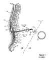
脊髄刺激は、ある一定の集団の患者の疼痛を低減するために広く受け入れられている臨床的方法である。SCSシステムは、典型的には、「埋め込み型パルス発生器(IPG)」、電極、少なくとも1つの電極リード、及び任意的に少なくとも1つの電極リード延長部を含む。図1に示すように、電極リード102の遠位端上に常駐する電極106は、典型的には、脊髄104の硬膜102に沿って埋め込まれ、IPG100は、電極106を通して脊柱104内の神経繊維に送出される電気パルスを発生させる。電極106は、望ましいパターン及び間隔で配置され、電極アレイ110を生成する。1つ又はそれよりも多くの電極リード102内の個々のワイヤ112は、アレイ110の各電極106と接続する。電極リード112は、脊柱104を出て、1つ又はそれよりも多くの電極リード延長部119a及び119bに取り付けることができる。電極リード延長部119a及び119bは、次に、典型的には、IPG100を埋め込む皮下ポケットまで患者の胴体の周囲でトンネルを通される。
Spinal cord stimulation is a widely accepted clinical method for reducing pain in a certain population of patients. SCS systems typically include an “implantable pulse generator (IPG)”, an electrode, at least one electrode lead, and optionally at least one electrode lead extension. As shown in FIG. 1, an
明らかなように、IPGは、機能するのに電力を必要とする。このような電力は、再充電可能又は再充電不能バッテリの使用を通して、又は外部充電器からの電磁(EM)誘導を通して、又は米国特許第6,553,263号明細書により詳細に説明されているこれら及び他の手法の組合せから提供されるようないくつかの異なる方法で提供することができる。恐らくそれらの手法のうちの好ましいものは、リチウムイオンバッテリ又はリチウムイオンポリマーバッテリのようなIPGの再充電可能バッテリを使用することである。このような再充電可能バッテリは、一般的に、十分な電力を供給し、再充電と再充電の間の十分な期間(例えば、1日又はそれよりも長く)にわたってIPGを稼動することができる。再充電は、EM場が外部充電器によってIPGに送られるEM誘導の使用により行うことができる。従って、IPGにおけるバッテリが再充電を必要とする時に、IPGが埋め込まれている患者は、外部充電器を起動させて経皮的に(患者の肌114を通して)バッテリを充電することができる(例えば、患者が眠っている時の夜に又は他の都合の良い期間中に)。図1Aでは、外部充電器は、全体的にコイル108によって表され、このコイルを使用して、患者の肌114を通して経皮的伝達が可能なEM場110を生成することができる。
As is apparent, IPG requires power to function. Such power is described in more detail through the use of rechargeable or non-rechargeable batteries, or through electromagnetic (EM) induction from an external charger, or by US Pat. No. 6,553,263. It can be provided in a number of different ways as provided by a combination of these and other approaches. Probably the preferred of those approaches is to use an IPG rechargeable battery such as a lithium ion battery or a lithium ion polymer battery. Such rechargeable batteries typically provide sufficient power and can run the IPG for a sufficient period of time between recharging (eg, one day or longer). . Recharging can be done by using EM induction where the EM field is sent to the IPG by an external charger. Thus, when the battery at the IPG needs recharging, the patient with the IPG implanted can activate the external charger to charge the battery transcutaneously (through the patient's skin 114) (eg, At night when the patient is asleep or during any other convenient period). In FIG. 1A, the external charger is generally represented by a
充電コイル(コイル108など)を保有するいくつかの基本的な種類の外部充電器設計は、従来技術で開示されている。例えば、米国特許公開第2009/0118796号明細書、米国特許公開第2010/0204756号明細書、及び米国特許公開第2008/027500号明細書を参照されたい。それらの従来技術の外部充電器の作動は、基本的に図2に示すように機能する。図示のように、システムは、関連部分に外部充電器158及びIPG100を含む。充電器158の1次コイル108は、患者の肌114を通して経皮的伝達が可能なEM場110を生成する。EM場110は、別のコイル200によるIPG100で交わり、従って、AC電圧が、その2次コイル200において誘導される。このAC電圧は、次に、標準ブリッジ回路を含むことができる整流器202においてDC電圧に整流される。(更に、EM場110に関連付けられたデータ遠隔測定が存在する場合があるが、この詳細は、本発明の開示とは無関係として無視される)。整流DC電圧は、次に、充電コントローラ及び保護回路204に送られ、これは、一般的にDC電圧を調節し、かつIPG100の内部再充電可能バッテリ206を再充電するのに必要であるような一定電圧又は一定電流Ibat出力のいずれかを生成するように作動する。外部充電器に関する更なる詳細は、’955出願に見出すことができる。
Several basic types of external charger designs that have a charging coil (such as coil 108) are disclosed in the prior art. See, for example, US Patent Publication No. 2009/0118796, US Patent Publication No. 2010/0204756, and US Patent Publication No. 2008/027500. The operation of these prior art external chargers basically functions as shown in FIG. As shown, the system includes an
図3に示すように、コイル108の下端でページの中に流れ込み、コイル108の上端でページから流れ出る電流は、1次コイル108が存在する平面に垂直な方向に顕著な部分のある磁場110を誘導する。1次コイル108は、典型的に、銅Litzワイヤの多くの巻回で形成され、そのうちの僅かに一握りの個々の巻回を明確にするために図3に示しているに過ぎない。従って、外部充電器158のケースの面が、埋め込まれた装置に近接して1次コイル108がIPG100内の対応する2次コイル200に平行であるような向きに配置される時に、1次コイル108によって発生する磁場は、対応するコイル200内に電流を誘導し、IPG100内のバッテリ214を充電するか又はそうでなければIPG100に電力を供給する。
As shown in FIG. 3, the current flowing into the page at the lower end of the
図3に示すように、遮蔽されていない1次コイルによって発生する磁場は、それが有用な仕事をする2次コイルに一部が向けられ、一部が2次コイルから離れるように向けられて磁場エネルギが実質的に浪費される磁場を発生する。1次コイルからのより高い割合の磁場を埋め込まれた2次コイルに向けることができるならば、外部充電器を駆動するのに必要なエネルギを低減することができ、これは、外部充電器をより小さくすることができるであろう。1次コイルからのより高い割合の磁場を身体に向ける1つのこのような方法は、米国特許第6,389,318号明細書に示すように1次コイルの巻線の背後で遮蔽された磁場を使用することである。このような設計は、磁力線を内向きに反射させて戻すことによって外部充電器/埋め込み型装置システムのエネルギ伝達効率を高めることができる。磁場シールドは、以下に限定されるものではないが、フェライト粉末又はフェライトプレートのような高透磁性を有するあらゆる材料で構成することができる。 As shown in FIG. 3, the magnetic field generated by the unshielded primary coil is partially directed toward the secondary coil where it does useful work and partially directed away from the secondary coil. A magnetic field is generated in which the magnetic field energy is substantially wasted. If a higher percentage of the magnetic field from the primary coil can be directed to the embedded secondary coil, the energy required to drive the external charger can be reduced, which will cause the external charger to Could be smaller. One such method of directing a higher percentage of the magnetic field from the primary coil to the body is a shielded magnetic field behind the winding of the primary coil as shown in US Pat. No. 6,389,318. Is to use. Such a design can increase the energy transfer efficiency of the external charger / implantable device system by reflecting the magnetic field lines back inward. The magnetic field shield is not limited to the following, but can be composed of any material having high magnetic permeability such as ferrite powder or ferrite plate.
従来的に、無線及び一体型(すなわち、単一の内蔵型パッケージに電源、充電コイル、及び関連の充電及び/又は遠隔測定回路を収容する)で小型及び薄型の外部充電器を生成する試みは、通常は再充電可能バッテリである外部充電器の電源のケーシングにおける過剰な加熱及び渦電流の発生によって複雑であった。従来技術の充電装置では、外部充電器のバッテリは、充電装置の内側に充電コイルの近くに置かれる。この近接性により、充電コイルによって生成される磁場は、バッテリケースに渦電流加熱を誘導する。これは、付加的な装置加熱並びに充電効率の低下の両方の望ましくない影響を有する。充電コイルによって伝達される電力の20%もが、充電コイルとバッテリの間のこの結合により失われる。 Traditionally, attempts to produce small and thin external chargers that are wireless and integrated (ie, containing the power supply, charging coil, and associated charging and / or telemetry circuitry in a single self-contained package) Complicated by excessive heating and the generation of eddy currents in the casing of the external charger power supply, usually a rechargeable battery. In the prior art charging device, the battery of the external charger is placed inside the charging device and near the charging coil. Due to this proximity, the magnetic field generated by the charging coil induces eddy current heating in the battery case. This has the undesirable effects of both additional device heating as well as reduced charging efficiency. As much as 20% of the power transmitted by the charging coil is lost due to this coupling between the charging coil and the battery.
それらの欠点を考慮すると、埋め込み可能装置の技術は、磁気シールドも含む一体型、小型、かつ薄型である無線外部充電器設計の改良から恩典を受けると考えられる。このような充電器は、充電効率の増大、より速い充電速度、患者の安全性及び快適性の増大、より低い電力要件、及びより小さい形状ファクタを提供するであろう。本発明の開示は、この問題に対する解決法を呈示し、ハウジングと、ハウジング内のコイルと、ハウジング内の再充電可能バッテリと、高透磁性材料で作られた1つ又は複数のプレートを含むハウジング内の磁気シールドとを含む外部充電器を開示し、磁気シールドは、バッテリとコイルの間に位置付けられ、コイル、バッテリ、及び磁気シールドは、同軸的に整列し、コイルを使用して、電力を埋め込み型医療装置に供給する。 In view of these shortcomings, implantable device technology would benefit from improvements in the design of a wireless external charger that is integrated, small, and thin, including a magnetic shield. Such a charger would provide increased charging efficiency, faster charging speed, increased patient safety and comfort, lower power requirements, and a smaller form factor. The present disclosure presents a solution to this problem and includes a housing, a coil in the housing, a rechargeable battery in the housing, and one or more plates made of a highly permeable material. An external charger including a magnetic shield within the coil, wherein the magnetic shield is positioned between the battery and the coil, the coil, the battery, and the magnetic shield are coaxially aligned and the coil is used to power Supply to implantable medical devices.
以下に示す説明は、脊柱刺激(SCS)システムにおける本発明の用途に関する。しかし、本発明は、そのように限定されるものではないことを理解すべきである。そうではなく、本発明は、外部充電器と埋め込み型装置の間の充電の改良から恩典を受けることができるあらゆるタイプの埋め込み型医療装置に使用することができる。例えば、本発明は、ペースメーカー、埋め込み型ポンプ、除細動器、蝸牛刺激器、網膜刺激器を充電するように構成された外部充電器、協働四肢移動を生成するように構成された刺激器、大脳皮質又は脳深部刺激器、又は尿失禁、睡眠時無呼吸、肩関節亜脱臼、その他を治療するように構成されたいずれかの他の神経刺激器を使用するシステムの一部として使用することができる。更に、この技術は、非医療及び/又は非埋め込み型装置又はシステムにおいて、すなわち、1次及び2次装置の間の結合の改良が必要か又は望ましいあらゆる装置又はシステムにおいても同様に使用することができる。 The following description relates to the use of the present invention in spinal column stimulation (SCS) systems. However, it should be understood that the invention is not so limited. Rather, the present invention can be used with any type of implantable medical device that can benefit from improved charging between an external charger and the implantable device. For example, the present invention includes pacemakers, implantable pumps, defibrillators, cochlear stimulators, external chargers configured to charge retinal stimulators, stimulators configured to generate cooperative limb movements Use as part of a system that uses cerebral cortex or deep brain stimulators or any other neural stimulator configured to treat urinary incontinence, sleep apnea, shoulder subluxation, etc. be able to. Furthermore, this technique may be used in non-medical and / or non-implantable devices or systems as well, i.e. in any device or system where an improved coupling between the primary and secondary devices is necessary or desirable. it can.
埋め込まれた医療装置を再充電するために、典型的には誘導充電器の形態の外部装置は、インプラントの上に置かれ、経皮的エネルギ伝達を提供する。外部充電装置は、再充電可能バッテリによって給電することができる。バッテリは、充電コイルに近接しているので、充電コイルによって生成された大きい磁場は、バッテリの金属ケースから流れる渦電流を誘導し、多くの場合、望ましくないバッテリの加熱及び充電器の効率の低下をもたらす。この開示は、渦電流加熱を低下させるように磁場からバッテリを遮蔽するための手段を提供し、それによって効率を増大させる。一実施形態では、磁気シールドは、1つ又はそれよりも多くの薄いフェライトプレートから構成される。フェライトシールドの使用は、充電コイルの外側とは対照的にバッテリを充電コイルの上に直接置くことを可能にする。別の実施形態では、磁気シールドは、1つ又はそれよりも多くの薄いフェライトプレートから構成されるバッテリ封入箱から構成される。フェライト箱の使用は、バッテリを完全に充電コイルの範囲に置くことを可能にする。 To recharge an implanted medical device, an external device, typically in the form of an inductive charger, is placed over the implant and provides transcutaneous energy transfer. The external charging device can be powered by a rechargeable battery. Because the battery is in close proximity to the charging coil, the large magnetic field generated by the charging coil induces eddy currents that flow from the metal case of the battery, often undesirably heating the battery and reducing the efficiency of the charger. Bring. This disclosure provides a means for shielding the battery from the magnetic field to reduce eddy current heating, thereby increasing efficiency. In one embodiment, the magnetic shield is composed of one or more thin ferrite plates. The use of a ferrite shield allows the battery to be placed directly on the charging coil as opposed to outside the charging coil. In another embodiment, the magnetic shield is comprised of a battery enclosure that is comprised of one or more thin ferrite plates. The use of a ferrite box allows the battery to be completely in the range of the charging coil.
図4は、一体型、小型、薄型、無線であり、全てが単一の内蔵型ハウジング内に同軸的に整列したバッテリ、コイル、及び磁気シールドを収容する埋め込み型装置を充電するための改良された外部充電器400の一実施形態を示している。外部充電器400は、外部充電器400を充電するために使用することができるベースユニット404に着座しているのが示されている。この実施形態では、4つの矢印形LEDライト402は、外部充電器400の表面上に配置され、1つの矢印形LEDライトは、外部充電器400の各縁部の方向を指す。LEDライト402は、一部の実施では、米国特許公開第2011/0004278号明細書において更に説明されているように、患者が外部充電器400を埋め込み型装置100とより良好に整列するのを補助するように使用することができる。
FIG. 4 shows an improvement for charging an implantable device that houses a battery, a coil, and a magnetic shield that are all-in-one, small, thin, wireless, all coaxially aligned within a single self-contained housing. 1 shows an embodiment of the external charger 400. External charger 400 is shown seated on a
図5A及び図5Bは、形状ファクタが図4に示す外部充電器400に類似している埋め込み型医療装置のための改良された外部充電器500の1つの可能な実施形態の外部構成要素の側面図及び底面図をそれぞれ示している。充電器500は、全てが単一のスタックにおいて同軸的に整列したバッテリ514、コイル108、及び磁気シールド504を収容する一体型、小型、薄型、無線外部充電器設計である。この実施形態の磁気シールドは、1つ又はそれよりも多くのタイル張りフェライトプレート504を含む。図5Aに示すように、外部充電器500はまた、中心軸512に沿って上半分510aと下半分510bに分けることができる、典型的には硬いプラスチックで形成されたケース又はハウジング510から構成される。クランプ502は、機械的に所定位置にプリント基板506を保持するのに使用することができる。クランプ502は、ケースの上半分の一部として形成されて示されているが、これは、他の手段を使用してケース510内の構成要素を安定化することができ、従って、厳密には必要でない。関連電子回路508は、あらゆる望ましい位置のPCB506上であるが、好ましくは、関連電子回路508においてあらゆる渦電流の発生を最小にするように磁気シールド504の背後に印刷することができる。バッテリ514は、コイル108からPCB506の反対側に置くことができる。円筒形バッテリではなくて薄いプリズム形バッテリは、薄型の充電器パッケージを考慮した充電器に使用することができる。例えば、PANASONIC(登録商標)からのリチウム鉄バッテリモデル第CGA633450Bは、34.0mm幅、50.0mm長、及びちょうど6.3mm厚の寸法を有する3.7V/1200mAh電源を提供する。
5A and 5B are external component side views of one possible embodiment of an improved
図5A−図5Bに示す充電器500のバッテリ514は、充電コイル108に近接しているので、充電コイルによって生成された大きい磁場は、磁気シールドがない場合、典型的にはアルミニウム又は鋼で構成されたバッテリ514の金属ケースから流れるような渦電流を誘導する傾向がある。それらの渦電流は、コイル108によって生成された磁場に対抗し、かつバッテリ514の不要な加熱及び充電器500の効率の低下をもたらすように作用する。従って、改良した外部充電器500設計の一実施形態は、渦電流加熱を低下させるように磁場からバッテリを遮蔽するための手段を提供し、それによって充電器500の効率を増大させる。図示の実施形態では、磁気シールドは、1つ又はそれよりも多くのフェライトプレート504を含むが、好ましくは、4つから6つのプレートを含む。フェライトプレートは、あらゆる形状を有することができるが、好ましくは、タイル張りのパターンの設置を考慮するように正方形又は矩形である。図5Bに示すように、磁場は、4つの正方形プレート504a〜504dから構成される場合がある。フェライトプレート504は、例えば、幅が26.42mmあり1.27mm厚である「LAIRD TECHNOLOGIES(登録商標)」からのモデル第HP1040−100とすることができる。各プレートはまた、必要な場合にPCB506のような表面に対して容易で簡単な適用を可能にする接着裏打ちを有する。プレート504の間の間隙516は、間隙を通る有意な漏れ磁束を防止するように、好ましくは、比較的小さく、理想的には1mm未満である。1つの大きいプレートでなくていくつかの小さいプレートを有する主要な利点は、フェライトが幾分脆弱であるので、より小さいプレートも方が構造的に1つの大きいプレートよりも強力であることである。同様に、複数の小さいプレートを製造する費用は、特に使用するフェライトが非常に薄い時に単一の大きいプレートを製造する費用よりも低価格である。代替的に、フェライトプレート504は、特に最大200kHzの周波数で電力を印加するように設計されたMnZn(マンガン亜鉛)フェライトである「FAIR−RITE(登録商標)Products Corp.」によって生成されたような「78 材料」を含むことができる。現在の用途では、インプラントの充電は、好ましくは、80kHzから120kHzの範囲で行われ、従って、78材料は、この周波数範囲においてその高透磁性(約2,000)により優れた選択肢である。
Since the
充電コイル108は、次に、PCB504の反対側に置かれた上述のようなバッテリ514によってフェライトプレート504に接着することができる。他の実施形態(図示せず)では、フェライトプレートは、コイル108の側面の反対側にバッテリが位置するPCB506の側面に置くことができる。フェライトシールド504の使用はまた、バッテリ514を充電コイル108の範囲外とは対照的に充電コイル108の上に直接置くことを可能にする。
The charging
タイル張りフェライトプレート504a〜504dを含む磁気シールドがなければ、外部充電器500は、充電効率の有意な低下を受けると考えられる。バッテリ514は、金属ケーシングを有し、従って、渦電流は、コイル108の誘導磁場110によってバッテリケーシングに発生すると考えられ、このような渦電流は、対抗する磁場を生成すると考えられる。それらの渦電流は、加熱損失の形態で金属バッテリケースに伝達されるエネルギをもたらす。従って、外部充電器は、バッテリ514のケースに消散している電力のために効率を失っていると考えられる。これは、埋め込まれた医療装置100を急速に充電させず、及び/又は外部充電器500のバッテリ514をより速く使い果たさせる。渦電流によって誘導された磁場は、コイル108によって誘導された磁場110の約5%の程度とすることができるに過ぎないが、それらの悪影響は、依然として有意と考えられる。更に、渦電流から生じる熱は不要である。
Without the magnetic shield including the tiled
しかし、フェライトプレート504を使用すると、それらの悪影響は減少する。図6に示すように、フェライトプレート504の透磁性の増大は、フェライトの内側の磁力線がコイル108に垂直ではなくてコイル108と平行な平面において流れるようにし、従って、磁場がバッテリ514に到達するのを迂回させる。更に、フェライトプレート504は、患者の身体から離れるように向けられているより少ない磁力線により充電システムの全体の効率を増大させ、ここで磁場エネルギが実質的に浪費される(図3と比較して)。磁気シールド504の設置により、1次コイル108からのより高い割合の磁場110は、皮膚境界114にわたって埋め込まれた2次コイル(図示せず)に向けられる。典型的には500から5000の範囲にあるフェライトシールドの相対的透磁性は、少なくとも部分的に、患者の埋め込まれた装置に戻る方向に磁束の「反射」により50%だけコイル108の線質係数を増加させることができる。
However, the use of ferrite plates 504 reduces their adverse effects. As shown in FIG. 6, the increased permeability of the ferrite plate 504 causes the magnetic field lines inside the ferrite to flow in a plane parallel to the
図7A及び図7Bは、図4に示す外部充電器400に形状ファクタが類似している埋め込み型医療装置のための改良された外部充電器700の代替的な実施形態の側面図及び底面図である。この実施形態では、磁気シールドは、良好な磁気シールド特性を有する材料、すなわち、上述のような高透磁性を有する材料で構成されたバッテリ封入フェライト箱702を含む。この代替的な実施形態では、フェライト箱702は、全ての側面からバッテリ514を覆う。しかし、箱は、上述の実施形態のようなプレートで作ることができ、従って、フェライト箱702は、それらの機能性を大幅に変えることはないと考えられる小さい間隙を含むことができる。
7A and 7B are side and bottom views of an alternative embodiment of an improved
外部充電器700は、図5A〜図5Bの外部充電器500に設計が類似している。しかし、外部充電器500の設計と異なり、かつちょうど図示するように、外部充電器700のバッテリ514は、フェライト箱702の内側に置かれる。フェライト箱702は、バッテリ、例えば、702a及び702bを封入する2つのクラムシェルプレート、又は全ての側面にバッテリを封入するタイル張りのパターンで配置された複数のプレートから構成することができる。この一実施形態の利点は、充電コイル108がフェライト箱702になくて(図5A及び図5Bを比較されたい)それを取り囲むので、ハウジング710をより薄くすることができる点である。しかし、1つの潜在的な欠点は、フェライト箱702が充電器の全重量を増加させる可能性があることであるが、これは適切なトレードオフとすることができる。同様に、切り欠き区域706が、バッテリ514及びフェライト箱構造702を収容するようにPCB704の中心で作られる必要があるので、PCB704の区域が幾分減少する。コイル108は、PCB704の外縁の周囲の長円形の平面構成に包まれたコイルを含むことができ、関連電子回路508は、コイル108の反対側のPCB704の側面上に印刷される。ここでもまた、充電器における円筒形バッテリではなく薄いプリズム形バッテリの使用は、薄型の外部充電器ハウジングを可能にする。
The
図8は、図7A及び図7Bの外部充電器700によって発生するそれぞれの磁力線110の側面図である。図6と同様に、フェライト箱702は、より少ない磁力線が後方にかつ磁場エネルギが浪費される患者の身体から離れるように向けられ、より充電システムの全体の効率を増大させることを見ることができる。1次コイル108からのより高い割合の磁場110は、皮膚境界114にわたって埋め込まれた2次コイルに向けられるが、コイルの範囲内にフェライト箱702を収容するのに必要な特定的な配置により、図6に見られるものほどその効果は大きくない。しかし、フェライト箱702は、バッテリ514のケーシングの力線110によって作り出された渦電流からのバッテリ514の優れた遮蔽をもたらす。
FIG. 8 is a side view of each
本発明の特定的な実施形態を図示して説明したが、上記説明は、本発明をそれらの実施形態に限定するように考えられるものではないことを理解すべきである。様々な変形及び修正を本発明の精神及び範囲から逸脱することなく行うことができることは当業者には明らかであろう。従って、本発明は、特許請求の範囲によって定めたような本発明の精神及び範囲に属することができる代替形態、修正、均等物を包含することを意図している。 While particular embodiments of the present invention have been illustrated and described, it should be understood that the above description is not intended to limit the invention to those embodiments. It will be apparent to those skilled in the art that various modifications and variations can be made without departing from the spirit and scope of the invention. Accordingly, the present invention is intended to embrace alternatives, modifications and equivalents that may fall within the spirit and scope of the invention as defined by the appended claims.
108 コイル
110 EM場
114 皮膚
500 充電器
508 電子回路
514 バッテリ
108
Claims (24)
ハウジングと、
前記ハウジング内のコイルと、
前記ハウジング内の再充電可能バッテリと、
高透磁性材料を含む前記ハウジング内の磁気シールドと、
を含み、
前記磁気シールドは、前記バッテリと前記コイルの間に位置付けられ、
前記コイルは、埋め込み型医療装置に電力を供給するのに使用される、
ことを特徴とする装置。 An external device for use with an implantable medical device comprising:
A housing;
A coil in the housing;
A rechargeable battery in the housing;
A magnetic shield in the housing comprising a highly permeable material;
Including
The magnetic shield is positioned between the battery and the coil;
The coil is used to power an implantable medical device;
A device characterized by that.
ハウジングと、
前記ハウジング内のコイルと、
前記ハウジング内の再充電可能バッテリと、
高透磁性材料で作られた複数のプレートを含む前記ハウジング内の磁気シールドと、
を含み、
前記磁気シールドは、前記バッテリと前記コイルの間に位置付けられ、
前記コイルは、埋め込み型医療装置に電力を供給するために使用される、
ことを特徴とする装置。 An external device for use with an implantable medical device comprising:
A housing;
A coil in the housing;
A rechargeable battery in the housing;
A magnetic shield in the housing comprising a plurality of plates made of a highly permeable material;
Including
The magnetic shield is positioned between the battery and the coil;
The coil is used to power an implantable medical device;
A device characterized by that.
前記複数のプレートは、実質的に前記コイルの範囲全体を覆うタイル張り配置に構成される、
ことを特徴とする請求項10に記載の装置。 Each of the plurality of plates is a ferrite plate,
The plurality of plates are configured in a tiled arrangement that covers substantially the entire area of the coil;
The apparatus according to claim 10.
ハウジングと、
前記ハウジング内のコイルと、
前記ハウジング内の再充電可能バッテリと、
高透磁性材料で作られた箱を含む前記ハウジング内の磁気シールドと、
を含み、
前記箱は、前記バッテリを覆い、
前記磁気シールド及びバッテリは、前記コイルの範囲内にあり、
前記コイルは、埋め込み型医療装置に電力を供給するために使用される、
ことを特徴とする装置。 An external device for use with an implantable medical device comprising:
A housing;
A coil in the housing;
A rechargeable battery in the housing;
A magnetic shield in the housing comprising a box made of a highly permeable material;
Including
The box covers the battery;
The magnetic shield and battery are within the coil;
The coil is used to power an implantable medical device;
A device characterized by that.
前記PCBは、前記バッテリ及び磁気シールドを収容するための切り欠き区域を有する、
ことを特徴とする請求項18に記載の装置。 A printed circuit board (PCB) in the housing of the external device;
The PCB has a cut-out area to accommodate the battery and magnetic shield.
The apparatus according to claim 18.
前記コイルは、前記PCBの第1の側面の外縁の周囲に位置付けられ、前記電子回路は、該PCBの第2の側面上に位置付けられる、
ことを特徴とする請求項21に記載の装置。 Further comprising an electronic circuit;
The coil is positioned around an outer edge of the first side of the PCB and the electronic circuit is positioned on a second side of the PCB;
The apparatus of claim 21.
Applications Claiming Priority (3)
| Application Number | Priority Date | Filing Date | Title |
|---|---|---|---|
| US31814310P | 2010-03-26 | 2010-03-26 | |
| US61/318,143 | 2010-03-26 | ||
| PCT/US2011/028071 WO2011119352A1 (en) | 2010-03-26 | 2011-03-11 | Inductive charger with magnetic shielding |
Publications (2)
| Publication Number | Publication Date |
|---|---|
| JP2013523260A true JP2013523260A (en) | 2013-06-17 |
| JP2013523260A5 JP2013523260A5 (en) | 2014-04-10 |
Family
ID=43951483
Family Applications (1)
| Application Number | Title | Priority Date | Filing Date |
|---|---|---|---|
| JP2013502609A Pending JP2013523260A (en) | 2010-03-26 | 2011-03-11 | Inductive charger with magnetic shield |
Country Status (7)
| Country | Link |
|---|---|
| US (2) | US9030159B2 (en) |
| EP (1) | EP2552541B1 (en) |
| JP (1) | JP2013523260A (en) |
| AU (1) | AU2011229869A1 (en) |
| CA (1) | CA2793182C (en) |
| ES (1) | ES2474592T3 (en) |
| WO (1) | WO2011119352A1 (en) |
Cited By (3)
| Publication number | Priority date | Publication date | Assignee | Title |
|---|---|---|---|---|
| JP2015535676A (en) * | 2012-11-29 | 2015-12-14 | ノキア テクノロジーズ オーユー | Inductive energy transfer coil structure |
| JP2016105694A (en) * | 2011-12-21 | 2016-06-09 | ボストン サイエンティフィック ニューロモデュレイション コーポレイション | System for implantable medical device having external charger connectable to accessory charging coil |
| JP2017502794A (en) * | 2013-11-11 | 2017-01-26 | ソーラテック コーポレイション | Resonant power transmission coil with hinge |
Families Citing this family (100)
| Publication number | Priority date | Publication date | Assignee | Title |
|---|---|---|---|---|
| US8811643B2 (en) | 2003-05-08 | 2014-08-19 | Advanced Bionics | Integrated cochlear implant headpiece |
| US8270647B2 (en) | 2003-05-08 | 2012-09-18 | Advanced Bionics, Llc | Modular speech processor headpiece |
| US8594806B2 (en) | 2010-04-30 | 2013-11-26 | Cyberonics, Inc. | Recharging and communication lead for an implantable device |
| EP2648135B1 (en) * | 2010-11-29 | 2019-07-17 | Fujitsu Limited | Portable device and power supply system |
| US9531195B2 (en) * | 2011-04-29 | 2016-12-27 | Cyberonics, Inc. | Inductively rechargeable implantable device with reduced eddy currents |
| US9059591B2 (en) | 2011-08-30 | 2015-06-16 | L&P Property Management Company | Docking station for inductively charged portable electronic device |
| KR101984642B1 (en) | 2011-09-30 | 2019-05-31 | 삼성전자주식회사 | Portable terminal with wireless charging module |
| WO2013048052A1 (en) * | 2011-09-30 | 2013-04-04 | 삼성전자 주식회사 | Portable terminal having a wireless charging module |
| US20150018728A1 (en) | 2012-01-26 | 2015-01-15 | Bluewind Medical Ltd. | Wireless neurostimulators |
| EP2841157A4 (en) * | 2012-04-27 | 2015-12-23 | Med El Elektromed Geraete Gmbh | Use of defined ferromagnetic materials for optimized implant coil coupling |
| US9325187B2 (en) * | 2012-05-21 | 2016-04-26 | Lg Electronics Inc. | Structure of transmission and reception unit in wireless charging system |
| US8886333B2 (en) | 2012-07-19 | 2014-11-11 | Boston Scientific Neuromodulation Corporation | Self-affixing external charging system for an implantable medical device |
| WO2014018971A1 (en) | 2012-07-27 | 2014-01-30 | Thoratec Corporation | Resonant power transfer systems with protective algorithm |
| US9805863B2 (en) | 2012-07-27 | 2017-10-31 | Thoratec Corporation | Magnetic power transmission utilizing phased transmitter coil arrays and phased receiver coil arrays |
| US9287040B2 (en) | 2012-07-27 | 2016-03-15 | Thoratec Corporation | Self-tuning resonant power transfer systems |
| US10383990B2 (en) | 2012-07-27 | 2019-08-20 | Tc1 Llc | Variable capacitor for resonant power transfer systems |
| EP2878061B1 (en) | 2012-07-27 | 2023-10-25 | Tc1 Llc | Thermal management for implantable wireless power transfer systems |
| US10291067B2 (en) | 2012-07-27 | 2019-05-14 | Tc1 Llc | Computer modeling for resonant power transfer systems |
| EP2878062A4 (en) * | 2012-07-27 | 2016-04-20 | Thoratec Corp | Resonant power transmission coils and systems |
| WO2014018969A2 (en) | 2012-07-27 | 2014-01-30 | Thoratec Corporation | Resonant power transfer system and method of estimating system state |
| US9087637B2 (en) | 2012-07-29 | 2015-07-21 | Qualcomm Incorporated | Universal apparatus for wireless device charging using radio frequency (RF) energy |
| US9343923B2 (en) | 2012-08-23 | 2016-05-17 | Cyberonics, Inc. | Implantable medical device with backscatter signal based communication |
| US9935498B2 (en) | 2012-09-25 | 2018-04-03 | Cyberonics, Inc. | Communication efficiency with an implantable medical device using a circulator and a backscatter signal |
| US20140114373A1 (en) | 2012-10-22 | 2014-04-24 | Boston Scientific Neuromodulation Corporation | Intermediate Coupler to Facilitate Charging in an Implantable Medical Device System |
| WO2014087337A1 (en) | 2012-12-06 | 2014-06-12 | Bluewind Medical Ltd. | Delivery of implantable neurostimulators |
| DE102013226228A1 (en) * | 2012-12-21 | 2014-06-26 | Robert Bosch Gmbh | Induktivladespulenvorrichtung |
| DE102013226226A1 (en) * | 2012-12-21 | 2014-06-26 | Robert Bosch Gmbh | Induktivladespulenvorrichtung |
| WO2014145895A1 (en) | 2013-03-15 | 2014-09-18 | Thoratec Corporation | Malleable tets coil with improved anatomical fit |
| WO2014145664A1 (en) | 2013-03-15 | 2014-09-18 | Thoratec Corporation | Integrated implantable tets housing including fins and coil loops |
| WO2015017474A2 (en) | 2013-07-29 | 2015-02-05 | Alfred E. Mann Foundation For Scientific Research | High efficiency magnetic link for implantable devices |
| CA2919474C (en) | 2013-07-29 | 2020-05-05 | Alfred E. Mann Foundation For Scientific Research | Microprocessor controlled class e driver |
| CN105517627B (en) * | 2013-09-06 | 2017-10-10 | 波士顿科学神经调制公司 | Induct the System and method for of heat for reducing the electromagnetic field from implantable impulse generator |
| CN105744986B (en) | 2013-09-16 | 2019-02-22 | 斯坦福大学董事会 | The multicomponent coupler generated for electromagnetic energy |
| JP6521992B2 (en) | 2013-11-11 | 2019-05-29 | ティーシー1 エルエルシー | Resonance power transmission system having communication |
| US10615642B2 (en) | 2013-11-11 | 2020-04-07 | Tc1 Llc | Resonant power transfer systems with communications |
| US9446251B1 (en) * | 2014-02-05 | 2016-09-20 | Micron Devices Llc | Handheld treatment device |
| US9445712B2 (en) * | 2014-02-25 | 2016-09-20 | Welch Allyn, Inc. | Medical device illuminator and charging system |
| WO2015134871A1 (en) | 2014-03-06 | 2015-09-11 | Thoratec Corporation | Electrical connectors for implantable devices |
| GB2527075A (en) | 2014-03-17 | 2015-12-16 | Daassist As | Percutaneous system, devices and methods |
| US9852844B2 (en) | 2014-03-24 | 2017-12-26 | Apple Inc. | Magnetic shielding in inductive power transfer |
| AU2015264517B2 (en) | 2014-05-18 | 2018-05-24 | NeuSpera Medical Inc. | Midfield coupler |
| US20160336813A1 (en) | 2015-05-15 | 2016-11-17 | NeuSpera Medical Inc. | Midfield coupler |
| US9782581B2 (en) | 2014-06-27 | 2017-10-10 | Boston Scientific Neuromodulation Corporation | Methods and systems for electrical stimulation including a shielded sheath |
| US10149933B2 (en) | 2014-07-25 | 2018-12-11 | Minnetronix, Inc. | Coil parameters and control |
| DE102015112097A1 (en) | 2014-07-25 | 2016-01-28 | Minnetronix, Inc. | power scale |
| US10186760B2 (en) | 2014-09-22 | 2019-01-22 | Tc1 Llc | Antenna designs for communication between a wirelessly powered implant to an external device outside the body |
| KR20160037652A (en) * | 2014-09-29 | 2016-04-06 | 엘지이노텍 주식회사 | Wireless power transmitting apparatus and wireless power receiving apparatus |
| US9583874B2 (en) | 2014-10-06 | 2017-02-28 | Thoratec Corporation | Multiaxial connector for implantable devices |
| DE102016100476A1 (en) | 2015-01-14 | 2016-07-14 | Minnetronix, Inc. | Decentralized transformer |
| DE102016100534A1 (en) | 2015-01-16 | 2016-07-21 | Vlad BLUVSHTEIN | Data transmission in a transcutaneous energy transmission system |
| KR102332095B1 (en) * | 2015-01-21 | 2021-11-30 | 삼성전자주식회사 | Wireless charging device |
| WO2016160423A1 (en) | 2015-03-27 | 2016-10-06 | Boston Scientific Neuromodulation Corporation | Systems and methods for making and using electrical stimulation systems to reduce rf-induced tissue heating |
| DE102016106657A1 (en) | 2015-04-14 | 2016-10-20 | Minnetronix, Inc. | REPEATER RESONANCE CIRCUIT |
| WO2016176645A1 (en) | 2015-04-30 | 2016-11-03 | Boston Scientific Neuromodulation Corporation | Electrical stimulation leads and systems having a rf shield along at least the lead and methods of making and using |
| WO2017025606A1 (en) * | 2015-08-12 | 2017-02-16 | Nuheart As | System, apparatus and method for improved contactless power transfer in implantable devices |
| US10148126B2 (en) | 2015-08-31 | 2018-12-04 | Tc1 Llc | Wireless energy transfer system and wearables |
| WO2017039420A1 (en) * | 2015-09-04 | 2017-03-09 | 주식회사 아모센스 | Magnetic shielding unit for wireless power transmission in magnetic resonance mode, and wireless power transmission module and electronic device comprising same |
| US20170084991A1 (en) * | 2015-09-17 | 2017-03-23 | Qualcomm Incorporated | Wireless power transfer antenna having a split shield |
| EP3902100A1 (en) | 2015-10-07 | 2021-10-27 | Tc1 Llc | Resonant power transfer systems having efficiency optimization based on receiver impedance |
| US10105540B2 (en) | 2015-11-09 | 2018-10-23 | Bluewind Medical Ltd. | Optimization of application of current |
| US10893847B2 (en) | 2015-12-30 | 2021-01-19 | Nuheart As | Transcatheter insertion system |
| US20170214268A1 (en) * | 2016-01-22 | 2017-07-27 | Boston Scientific Neuromodulation Corporation | Physically-Configurable External Charger for an Implantable Medical Device with Separable Coil and Electronics Housings |
| US11175161B2 (en) * | 2016-02-23 | 2021-11-16 | Mediatek Inc. | Inductive sensor for position/orientation sensing |
| US11904234B2 (en) * | 2016-02-23 | 2024-02-20 | Mediatek Inc. | Position tracking ring, band or bracelet and virtual reality system |
| WO2017165410A1 (en) | 2016-03-21 | 2017-09-28 | Nalu Medical, Inc. | Devices and methods for positioning external devices in relation to implanted devices |
| EP3244509B1 (en) | 2016-05-11 | 2020-09-16 | Greatbatch Ltd. | Wireless charging autoclavable batteries inside a sterilizable tray |
| US10226637B2 (en) | 2016-06-15 | 2019-03-12 | Boston Scientific Neuromodulation Corporation | External charger for an implantable medical device having alignment and centering capabilities |
| US10603501B2 (en) | 2016-06-15 | 2020-03-31 | Boston Scientific Neuromodulation Corporation | External charger for an implantable medical device having at least one sense coil concentric with a charging coil for determining position |
| US10342984B2 (en) | 2016-06-15 | 2019-07-09 | Boston Scientific Neuromodulation Corporation | Split coil for uniform magnetic field generation from an external charger for an implantable medical device |
| US10363426B2 (en) | 2016-06-15 | 2019-07-30 | Boston Scientific Neuromodulation Corporation | External charger for an implantable medical device for determining position using phase angle or a plurality of parameters as determined from at least one sense coil |
| US11129996B2 (en) | 2016-06-15 | 2021-09-28 | Boston Scientific Neuromodulation Corporation | External charger for an implantable medical device for determining position and optimizing power transmission using resonant frequency as determined from at least one sense coil |
| US11471692B2 (en) | 2016-06-15 | 2022-10-18 | Boston Scientific Neuromodulation Corporation | External charger for an implantable medical device for adjusting charging power based on determined position using at least one sense coil |
| CN106160126A (en) * | 2016-09-08 | 2016-11-23 | 苏州景昱医疗器械有限公司 | Wireless charging device |
| WO2018057563A1 (en) | 2016-09-21 | 2018-03-29 | Tc1 Llc | Systems and methods for locating implanted wireless power transmission devices |
| US10335528B2 (en) | 2016-10-07 | 2019-07-02 | Nuheart As | Transcatheter method and system for the delivery of intracorporeal devices |
| US10537672B2 (en) | 2016-10-07 | 2020-01-21 | Nuheart As | Transcatheter device and system for the delivery of intracorporeal devices |
| US10881869B2 (en) | 2016-11-21 | 2021-01-05 | Cardiac Pacemakers, Inc. | Wireless re-charge of an implantable medical device |
| CN109963618B (en) | 2016-11-21 | 2023-07-04 | 心脏起搏器股份公司 | Leadless cardiac pacemaker with multi-mode communication |
| CN109996585B (en) | 2016-11-21 | 2023-06-13 | 心脏起搏器股份公司 | Implantable medical device with magnetically permeable housing and induction coil disposed around the housing |
| US10124178B2 (en) | 2016-11-23 | 2018-11-13 | Bluewind Medical Ltd. | Implant and delivery tool therefor |
| EP3562543A4 (en) * | 2016-12-30 | 2020-11-11 | Nalu Medical, Inc. | Stimulation apparatus |
| US11197990B2 (en) | 2017-01-18 | 2021-12-14 | Tc1 Llc | Systems and methods for transcutaneous power transfer using microneedles |
| US11177695B2 (en) * | 2017-02-13 | 2021-11-16 | Nucurrent, Inc. | Transmitting base with magnetic shielding and flexible transmitting antenna |
| US10632318B2 (en) | 2017-03-21 | 2020-04-28 | Boston Scientific Neuromodulation Corporation | External charger with three-axis magnetic field sensor to determine implantable medical device position |
| US11177680B2 (en) * | 2017-04-04 | 2021-11-16 | Intel Corporation | Field shaper for a wireless power transmitter |
| US10888646B2 (en) | 2017-04-28 | 2021-01-12 | Nuheart As | Ventricular assist device and method |
| US10537670B2 (en) | 2017-04-28 | 2020-01-21 | Nuheart As | Ventricular assist device and method |
| US11283295B2 (en) | 2017-05-26 | 2022-03-22 | Nucurrent, Inc. | Device orientation independent wireless transmission system |
| US10888706B2 (en) | 2017-06-02 | 2021-01-12 | Boston Scientific Neuromodulation Corporation | External charger for an implantable medical device having a thermal diffuser |
| US20180353764A1 (en) | 2017-06-13 | 2018-12-13 | Bluewind Medical Ltd. | Antenna configuration |
| US10918875B2 (en) | 2017-08-18 | 2021-02-16 | Cardiac Pacemakers, Inc. | Implantable medical device with a flux concentrator and a receiving coil disposed about the flux concentrator |
| EP3735733B1 (en) | 2018-01-04 | 2024-01-17 | Tc1 Llc | Systems and methods for elastic wireless power transmission devices |
| US11642537B2 (en) | 2019-03-11 | 2023-05-09 | Axonics, Inc. | Charging device with off-center coil |
| CN110441673A (en) * | 2019-08-27 | 2019-11-12 | 清华大学 | Active implantable medical device wireless charging and communication coil are fixedly connected with component |
| US11888325B2 (en) * | 2019-12-18 | 2024-01-30 | Medtronic, Inc. | Implantable medical system with external power charger |
| US11283303B2 (en) | 2020-07-24 | 2022-03-22 | Nucurrent, Inc. | Area-apportioned wireless power antenna for maximized charging volume |
| US11695302B2 (en) * | 2021-02-01 | 2023-07-04 | Nucurrent, Inc. | Segmented shielding for wide area wireless power transmitter |
| US11400299B1 (en) | 2021-09-14 | 2022-08-02 | Rainbow Medical Ltd. | Flexible antenna for stimulator |
| WO2023089428A1 (en) * | 2021-11-16 | 2023-05-25 | Cochlear Limited | Wearable device heat management |
| WO2024030614A1 (en) * | 2022-08-05 | 2024-02-08 | Resonant Link, Inc. | High efficiency wireless power transfer to implantable devices |
Citations (10)
| Publication number | Priority date | Publication date | Assignee | Title |
|---|---|---|---|---|
| JPH0279583U (en) * | 1988-12-07 | 1990-06-19 | ||
| JPH05317433A (en) * | 1992-05-26 | 1993-12-03 | Kaajio P-Shingu Res Lab:Kk | Pace maker |
| US5948006A (en) * | 1998-10-14 | 1999-09-07 | Advanced Bionics Corporation | Transcutaneous transmission patch |
| JP2000183583A (en) * | 1998-12-17 | 2000-06-30 | Ohbayashi Corp | Method for manufacturing precast concrete slab with electronic wave absorbing function |
| JP2004519315A (en) * | 2001-05-23 | 2004-07-02 | コックリアー,リミテッド | Transceiver coil for artificial hearing organ |
| JP2004534495A (en) * | 2001-05-23 | 2004-11-11 | アン,テ・ヨン | Non-contact power supply for implantable medical devices |
| US6850803B1 (en) * | 2000-06-16 | 2005-02-01 | Medtronic, Inc. | Implantable medical device with a recharging coil magnetic shield |
| US20050075696A1 (en) * | 2003-10-02 | 2005-04-07 | Medtronic, Inc. | Inductively rechargeable external energy source, charger, system and method for a transcutaneous inductive charger for an implantable medical device |
| JP2008519399A (en) * | 2004-10-29 | 2008-06-05 | メドトロニック・インコーポレーテッド | Lithium-ion battery and medical device |
| US20100036458A1 (en) * | 2008-08-08 | 2010-02-11 | Med-El Elektromedizinische Geraete Gmbh | External Button Processor with a Rechargeable Battery |
Family Cites Families (27)
| Publication number | Priority date | Publication date | Assignee | Title |
|---|---|---|---|---|
| US3626345A (en) * | 1969-10-13 | 1971-12-07 | Toko Inc | Radiofrequency transformer |
| US4071032A (en) * | 1976-01-29 | 1978-01-31 | Pacesetter Systems Inc. | Implantable living tissue stimulators |
| JPH0279583A (en) | 1988-09-14 | 1990-03-20 | Sharp Corp | Optical transmittivity variable type liquid crystal display device |
| JPH0816745A (en) * | 1994-06-24 | 1996-01-19 | Seiko Instr Inc | Ic card system |
| US5761053A (en) * | 1996-05-08 | 1998-06-02 | W. L. Gore & Associates, Inc. | Faraday cage |
| EP1011792B1 (en) * | 1997-02-26 | 2005-12-07 | Alfred E. Mann Foundation for Scientific Research | Battery-powered patient implantable device |
| US6324430B1 (en) | 1998-07-06 | 2001-11-27 | Abiomed, Inc. | Magnetic shield for primary coil of transcutaneous energy transfer device |
| US6324431B1 (en) | 1998-07-06 | 2001-11-27 | Abiomed, Inc. | Transcutaneous energy transfer device with magnetic field protected components in secondary coil |
| US6389318B1 (en) | 1998-07-06 | 2002-05-14 | Abiomed, Inc. | Magnetic shield for primary coil of transcutaneous energy transfer device |
| CN1300203A (en) | 1999-04-14 | 2001-06-20 | 皇家菲利浦电子有限公司 | Device with rechargeable battery |
| US6553263B1 (en) * | 1999-07-30 | 2003-04-22 | Advanced Bionics Corporation | Implantable pulse generators using rechargeable zero-volt technology lithium-ion batteries |
| JP2001166319A (en) * | 1999-12-09 | 2001-06-22 | Sony Corp | Liquid crystal display device |
| US7286881B2 (en) * | 2003-10-02 | 2007-10-23 | Medtronic, Inc. | External power source having an adjustable magnetic core and method of use |
| US7286880B2 (en) * | 2003-10-02 | 2007-10-23 | Medtronic, Inc. | System and method for transcutaneous energy transfer achieving high efficiency |
| US7225032B2 (en) * | 2003-10-02 | 2007-05-29 | Medtronic Inc. | External power source, charger and system for an implantable medical device having thermal characteristics and method therefore |
| US7505816B2 (en) | 2005-04-29 | 2009-03-17 | Medtronic, Inc. | Actively cooled external energy source, external charger, system of transcutaneous energy transfer, system of transcutaneous charging and method therefore |
| US8606362B2 (en) | 2005-07-08 | 2013-12-10 | Boston Scientific Neuromodulation Corporation | Current output architecture for an implantable stimulator device |
| KR101052981B1 (en) * | 2006-03-24 | 2011-07-29 | 도시바 마테리알 가부시키가이샤 | Non-contact type power receiving device, electronic device and non-contact charging device using the same |
| US9002445B2 (en) | 2006-07-28 | 2015-04-07 | Boston Scientific Neuromodulation Corporation | Charger with orthogonal PCB for implantable medical device |
| WO2008035248A2 (en) * | 2006-09-18 | 2008-03-27 | Philips Intellectual Property & Standards Gmbh | An apparatus, a system and a method for enabling electromagnetic energy transfer |
| US7769457B2 (en) * | 2007-08-04 | 2010-08-03 | Cameron Health, Inc. | Electromagnetic interference shielding in an implantable medical device |
| US8498716B2 (en) | 2007-11-05 | 2013-07-30 | Boston Scientific Neuromodulation Corporation | External controller for an implantable medical device system with coupleable external charging coil assembly |
| US9259591B2 (en) * | 2007-12-28 | 2016-02-16 | Cyberonics, Inc. | Housing for an implantable medical device |
| US8335569B2 (en) | 2009-02-10 | 2012-12-18 | Boston Scientific Neuromodulation Corporation | External device for communicating with an implantable medical device having data telemetry and charging integrated in a single housing |
| EP2433347B1 (en) | 2009-05-20 | 2013-10-23 | Koninklijke Philips N.V. | Electronic device having an inductive receiver coil with ultra-thin shielding layer and method |
| US8473066B2 (en) | 2009-07-06 | 2013-06-25 | Boston Scientific Neuromodulation Company | External charger for a medical implantable device using field sensing coils to improve coupling |
| US8321029B2 (en) | 2009-09-18 | 2012-11-27 | Boston Scientific Neuromodulation Corporation | External charger usable with an implantable medical device having a programmable or time-varying temperature set point |
-
2011
- 2011-03-04 US US13/040,945 patent/US9030159B2/en active Active
- 2011-03-11 AU AU2011229869A patent/AU2011229869A1/en not_active Abandoned
- 2011-03-11 EP EP11709594.3A patent/EP2552541B1/en active Active
- 2011-03-11 ES ES11709594.3T patent/ES2474592T3/en active Active
- 2011-03-11 CA CA2793182A patent/CA2793182C/en not_active Expired - Fee Related
- 2011-03-11 JP JP2013502609A patent/JP2013523260A/en active Pending
- 2011-03-11 WO PCT/US2011/028071 patent/WO2011119352A1/en active Application Filing
-
2015
- 2015-04-27 US US14/696,866 patent/US9636508B2/en active Active
Patent Citations (10)
| Publication number | Priority date | Publication date | Assignee | Title |
|---|---|---|---|---|
| JPH0279583U (en) * | 1988-12-07 | 1990-06-19 | ||
| JPH05317433A (en) * | 1992-05-26 | 1993-12-03 | Kaajio P-Shingu Res Lab:Kk | Pace maker |
| US5948006A (en) * | 1998-10-14 | 1999-09-07 | Advanced Bionics Corporation | Transcutaneous transmission patch |
| JP2000183583A (en) * | 1998-12-17 | 2000-06-30 | Ohbayashi Corp | Method for manufacturing precast concrete slab with electronic wave absorbing function |
| US6850803B1 (en) * | 2000-06-16 | 2005-02-01 | Medtronic, Inc. | Implantable medical device with a recharging coil magnetic shield |
| JP2004519315A (en) * | 2001-05-23 | 2004-07-02 | コックリアー,リミテッド | Transceiver coil for artificial hearing organ |
| JP2004534495A (en) * | 2001-05-23 | 2004-11-11 | アン,テ・ヨン | Non-contact power supply for implantable medical devices |
| US20050075696A1 (en) * | 2003-10-02 | 2005-04-07 | Medtronic, Inc. | Inductively rechargeable external energy source, charger, system and method for a transcutaneous inductive charger for an implantable medical device |
| JP2008519399A (en) * | 2004-10-29 | 2008-06-05 | メドトロニック・インコーポレーテッド | Lithium-ion battery and medical device |
| US20100036458A1 (en) * | 2008-08-08 | 2010-02-11 | Med-El Elektromedizinische Geraete Gmbh | External Button Processor with a Rechargeable Battery |
Cited By (4)
| Publication number | Priority date | Publication date | Assignee | Title |
|---|---|---|---|---|
| JP2016105694A (en) * | 2011-12-21 | 2016-06-09 | ボストン サイエンティフィック ニューロモデュレイション コーポレイション | System for implantable medical device having external charger connectable to accessory charging coil |
| JP2015535676A (en) * | 2012-11-29 | 2015-12-14 | ノキア テクノロジーズ オーユー | Inductive energy transfer coil structure |
| US9973023B2 (en) | 2012-11-29 | 2018-05-15 | Provenance Asset Group Llc | Inductive energy transfer coil structure |
| JP2017502794A (en) * | 2013-11-11 | 2017-01-26 | ソーラテック コーポレイション | Resonant power transmission coil with hinge |
Also Published As
| Publication number | Publication date |
|---|---|
| ES2474592T3 (en) | 2014-07-09 |
| CA2793182A1 (en) | 2011-09-29 |
| EP2552541A1 (en) | 2013-02-06 |
| US9636508B2 (en) | 2017-05-02 |
| CA2793182C (en) | 2015-11-17 |
| AU2011229869A1 (en) | 2012-10-04 |
| US20110234155A1 (en) | 2011-09-29 |
| EP2552541B1 (en) | 2014-06-18 |
| US20150224323A1 (en) | 2015-08-13 |
| WO2011119352A1 (en) | 2011-09-29 |
| US9030159B2 (en) | 2015-05-12 |
Similar Documents
| Publication | Publication Date | Title |
|---|---|---|
| US9636508B2 (en) | Inductive charger with magnetic shielding | |
| US9333367B2 (en) | Charger with orthogonal PCB for implantable medical device | |
| US10806937B2 (en) | Heat dispersion for implantable medical devices | |
| US7979126B2 (en) | Orientation-independent implantable pulse generator | |
| AU753694B2 (en) | Implantable device with improved battery recharging and powering configuration | |
| US9399131B2 (en) | Moldable charger with support members for charging an implantable pulse generator | |
| US20050288743A1 (en) | Implantable medical device with contactless power transfer housing | |
| US20090171420A1 (en) | Housing for an Implantable Medical Device | |
| EP2908907A1 (en) | Intermediate coupler to facilitate charging in an implantable medical device system | |
| US20110270349A1 (en) | Recharging and communication lead for an implantable device | |
| US20150066113A1 (en) | Radiolucent Metal Case Plate to Facilitate Communications in an Implantable Medical Device | |
| AU2014262220B2 (en) | Inductive charger with magnetic shielding | |
| EP1424098B1 (en) | Implantable device with improved battery recharging and powering configuration | |
| US20170361112A1 (en) | External Charger for an Implantable Medical Device Having a Multi-Layer Magnetic Shield | |
| AU775343B2 (en) | Implantable device with improved battery recharging and powering configuration |
Legal Events
| Date | Code | Title | Description |
|---|---|---|---|
| A977 | Report on retrieval |
Free format text: JAPANESE INTERMEDIATE CODE: A971007 Effective date: 20131011 |
|
| A131 | Notification of reasons for refusal |
Free format text: JAPANESE INTERMEDIATE CODE: A131 Effective date: 20131015 |
|
| A601 | Written request for extension of time |
Free format text: JAPANESE INTERMEDIATE CODE: A601 Effective date: 20140115 |
|
| A602 | Written permission of extension of time |
Free format text: JAPANESE INTERMEDIATE CODE: A602 Effective date: 20140122 |
|
| A524 | Written submission of copy of amendment under article 19 pct |
Free format text: JAPANESE INTERMEDIATE CODE: A524 Effective date: 20140217 |
|
| A02 | Decision of refusal |
Free format text: JAPANESE INTERMEDIATE CODE: A02 Effective date: 20140519 |