JP2013521533A - Composite multilayer structure with nanostructured surface - Google Patents
Composite multilayer structure with nanostructured surface Download PDFInfo
- Publication number
- JP2013521533A JP2013521533A JP2012556132A JP2012556132A JP2013521533A JP 2013521533 A JP2013521533 A JP 2013521533A JP 2012556132 A JP2012556132 A JP 2012556132A JP 2012556132 A JP2012556132 A JP 2012556132A JP 2013521533 A JP2013521533 A JP 2013521533A
- Authority
- JP
- Japan
- Prior art keywords
- nanostructured
- transparent conductive
- composite according
- major surface
- article
- Prior art date
- Legal status (The legal status is an assumption and is not a legal conclusion. Google has not performed a legal analysis and makes no representation as to the accuracy of the status listed.)
- Pending
Links
Images


Classifications
-
- B—PERFORMING OPERATIONS; TRANSPORTING
- B32—LAYERED PRODUCTS
- B32B—LAYERED PRODUCTS, i.e. PRODUCTS BUILT-UP OF STRATA OF FLAT OR NON-FLAT, e.g. CELLULAR OR HONEYCOMB, FORM
- B32B33/00—Layered products characterised by particular properties or particular surface features, e.g. particular surface coatings; Layered products designed for particular purposes not covered by another single class
-
- B—PERFORMING OPERATIONS; TRANSPORTING
- B82—NANOTECHNOLOGY
- B82Y—SPECIFIC USES OR APPLICATIONS OF NANOSTRUCTURES; MEASUREMENT OR ANALYSIS OF NANOSTRUCTURES; MANUFACTURE OR TREATMENT OF NANOSTRUCTURES
- B82Y20/00—Nanooptics, e.g. quantum optics or photonic crystals
-
- B—PERFORMING OPERATIONS; TRANSPORTING
- B82—NANOTECHNOLOGY
- B82Y—SPECIFIC USES OR APPLICATIONS OF NANOSTRUCTURES; MEASUREMENT OR ANALYSIS OF NANOSTRUCTURES; MANUFACTURE OR TREATMENT OF NANOSTRUCTURES
- B82Y30/00—Nanotechnology for materials or surface science, e.g. nanocomposites
-
- C—CHEMISTRY; METALLURGY
- C09—DYES; PAINTS; POLISHES; NATURAL RESINS; ADHESIVES; COMPOSITIONS NOT OTHERWISE PROVIDED FOR; APPLICATIONS OF MATERIALS NOT OTHERWISE PROVIDED FOR
- C09D—COATING COMPOSITIONS, e.g. PAINTS, VARNISHES OR LACQUERS; FILLING PASTES; CHEMICAL PAINT OR INK REMOVERS; INKS; CORRECTING FLUIDS; WOODSTAINS; PASTES OR SOLIDS FOR COLOURING OR PRINTING; USE OF MATERIALS THEREFOR
- C09D5/00—Coating compositions, e.g. paints, varnishes or lacquers, characterised by their physical nature or the effects produced; Filling pastes
- C09D5/006—Anti-reflective coatings
-
- G—PHYSICS
- G02—OPTICS
- G02B—OPTICAL ELEMENTS, SYSTEMS OR APPARATUS
- G02B1/00—Optical elements characterised by the material of which they are made; Optical coatings for optical elements
- G02B1/10—Optical coatings produced by application to, or surface treatment of, optical elements
- G02B1/11—Anti-reflection coatings
- G02B1/118—Anti-reflection coatings having sub-optical wavelength surface structures designed to provide an enhanced transmittance, e.g. moth-eye structures
-
- B—PERFORMING OPERATIONS; TRANSPORTING
- B32—LAYERED PRODUCTS
- B32B—LAYERED PRODUCTS, i.e. PRODUCTS BUILT-UP OF STRATA OF FLAT OR NON-FLAT, e.g. CELLULAR OR HONEYCOMB, FORM
- B32B2307/00—Properties of the layers or laminate
- B32B2307/20—Properties of the layers or laminate having particular electrical or magnetic properties, e.g. piezoelectric
- B32B2307/202—Conductive
-
- B—PERFORMING OPERATIONS; TRANSPORTING
- B32—LAYERED PRODUCTS
- B32B—LAYERED PRODUCTS, i.e. PRODUCTS BUILT-UP OF STRATA OF FLAT OR NON-FLAT, e.g. CELLULAR OR HONEYCOMB, FORM
- B32B2307/00—Properties of the layers or laminate
- B32B2307/40—Properties of the layers or laminate having particular optical properties
- B32B2307/412—Transparent
-
- B—PERFORMING OPERATIONS; TRANSPORTING
- B32—LAYERED PRODUCTS
- B32B—LAYERED PRODUCTS, i.e. PRODUCTS BUILT-UP OF STRATA OF FLAT OR NON-FLAT, e.g. CELLULAR OR HONEYCOMB, FORM
- B32B2307/00—Properties of the layers or laminate
- B32B2307/70—Other properties
- B32B2307/724—Permeability to gases, adsorption
- B32B2307/7242—Non-permeable
-
- G—PHYSICS
- G02—OPTICS
- G02B—OPTICAL ELEMENTS, SYSTEMS OR APPARATUS
- G02B2207/00—Coding scheme for general features or characteristics of optical elements and systems of subclass G02B, but not including elements and systems which would be classified in G02B6/00 and subgroups
- G02B2207/101—Nanooptics
-
- Y—GENERAL TAGGING OF NEW TECHNOLOGICAL DEVELOPMENTS; GENERAL TAGGING OF CROSS-SECTIONAL TECHNOLOGIES SPANNING OVER SEVERAL SECTIONS OF THE IPC; TECHNICAL SUBJECTS COVERED BY FORMER USPC CROSS-REFERENCE ART COLLECTIONS [XRACs] AND DIGESTS
- Y10—TECHNICAL SUBJECTS COVERED BY FORMER USPC
- Y10T—TECHNICAL SUBJECTS COVERED BY FORMER US CLASSIFICATION
- Y10T428/00—Stock material or miscellaneous articles
- Y10T428/24—Structurally defined web or sheet [e.g., overall dimension, etc.]
- Y10T428/24355—Continuous and nonuniform or irregular surface on layer or component [e.g., roofing, etc.]
Abstract
ランダムナノ構造化異方性主表面を有するナノ構造化物品。 A nanostructured article having a random nanostructured anisotropic main surface.
Description
光が1つの媒体から他の媒体へと移動する際に、光の一部は、2つの媒体の間の境界面から反射される。例えば、透明なプラスチック基材上で光っている光の、典型的には約4〜5%は上面で反射される。 As light travels from one medium to another, some of the light is reflected from the interface between the two media. For example, typically about 4-5% of the light shining on a transparent plastic substrate is reflected from the top surface.
高分子材料の反射を低減させるために、様々なアプローチが採用されている。1つのアプローチは、例えば、反射を低減させるよう屈折率にコントラストをもたらす交互の層を備える、透明な薄膜構造体からなる、多層反射コーティングなどの反射防止コーティングを使用することである。しかしながら、多層反射防止用コーティング技術により広帯域の反射防止を達成することは難しい。 Various approaches have been taken to reduce the reflection of polymeric materials. One approach is to use an anti-reflective coating, such as a multilayer reflective coating, consisting of a transparent thin film structure, for example, with alternating layers that provide contrast to the refractive index to reduce reflection. However, it is difficult to achieve broadband antireflection by multilayer antireflection coating technology.
他のアプローチは、広帯域反射防止のために、サブ波長の表面構造体(例えば、サブ波長スケールの表面グレーティング)を使用することを伴う。リソグラフィなどでサブ波長表面構造体を作製する方法は、複雑でかつ費用がかかる傾向がある。加えて、サブ波長スケールの表面グレーティングを用いるロール・ツー・ロールプロセスにより、一貫して低反射性である広帯域反射防止(すなわち、可視範囲にわたる平均反射が0.5%未満)を得ることは、困難ではあるがやりがいがある。その一方で、高性能で、比較的低反射(すなわち、可視範囲にわたる平均反射が0.5%未満)で、比較的低複屈折(すなわち、光遅延値が200nm未満)の反射防止用物品が、光学薄膜用途に所望される。 Another approach involves using subwavelength surface structures (eg, subwavelength scale surface gratings) for broadband antireflection. Methods for producing subwavelength surface structures such as by lithography tend to be complex and expensive. In addition, a roll-to-roll process using sub-wavelength scale surface gratings provides broadband antireflection that is consistently low reflective (ie, average reflection over the visible range of less than 0.5%) Difficult but rewarding. On the other hand, an anti-reflective article having high performance, relatively low reflection (ie, average reflection over the visible range of less than 0.5%), and relatively low birefringence (ie, optical delay value of less than 200 nm). Desirable for optical thin film applications.
一態様では、本開示は:
概して向かい合う第一及び第二主表面を有する基材;
概して向かい合う第一及び第二主表面を有する第一機能層、ここで、第一機能層の第一主表面は、基材の第一主表面上に配置され、かつ第一機能層は透明な導電層又はガスバリア層のうちの少なくとも1つである;及び
第一機能層の第二主表面上に配置された第一ナノ構造化物品;を含み、第一ナノ構造化物品が、第一マトリックス及び第一ナノスケール分散相を含み、かつ第一ランダムナノ構造化異方性表面を有する、複合体を提供する。一部の実施形態では、複合体は更に:
概して向かい合う第一及び第二主表面を有する第二機能層、ここで、第二機能層の第一主表面は、基材の第二主表面上に配置され、かつ第二機能層は透明な導電層又はガスバリア層のうちの少なくとも1つである;及び
第二機能層の第二主表面上に配置された第二ナノ構造化物品;を含み、第二ナノ構造化物品は、第二マトリックス及び第二ナノスケール分散相を含み、かつ第二ランダムナノ構造化異方性表面を有する。あるいは、例えば一部の実施形態では、複合体は更に:
概して向かい合う第一及び第二主表面を有する第二ナノ構造化物品、ここで、第二ナノ構造化物品の第一主表面は、基材の第二主表面上に配置され、第二ナノ構造化物品は、第二マトリックス及び第二ナノスケール分散相を含み、かつ第二ナノ構造化物品の第二主表面にて第二ランダムナノ構造化異方性表面を有する;及び
概して向かい合う第一及び第二主表面を有する第二機能層;を含み、ここで、第二機能層の第一主表面は、第二ナノ構造化物品の第二主表面上に配置され、かつ第二機能層は透明な導電層又はガスバリア層のうちの少なくとも1つである。
In one aspect, the disclosure provides:
A substrate having first and second major surfaces generally facing each other;
A first functional layer having first and second major surfaces generally facing each other, wherein the first major surface of the first functional layer is disposed on the first major surface of the substrate and the first functional layer is transparent. A first nanostructured article disposed on the second major surface of the first functional layer, wherein the first nanostructured article is a first matrix And a first nanoscale dispersed phase and having a first random nanostructured anisotropic surface. In some embodiments, the complex further comprises:
A second functional layer having first and second major surfaces generally facing each other, wherein the first major surface of the second functional layer is disposed on the second major surface of the substrate and the second functional layer is transparent. A second nanostructured article, wherein the second nanostructured article is disposed on the second major surface of the second functional layer, the second nanostructured article being at least one of a conductive layer or a gas barrier layer; And a second nanoscale dispersed phase and having a second random nanostructured anisotropic surface. Alternatively, for example, in some embodiments, the complex further comprises:
A second nanostructured article having first and second major surfaces generally facing each other, wherein the first major surface of the second nanostructured article is disposed on the second major surface of the substrate and the second nanostructured The structured article includes a second matrix and a second nanoscale dispersed phase and has a second random nanostructured anisotropic surface at the second major surface of the second nanostructured article; and a generally opposed first and A second functional layer having a second major surface, wherein the first major surface of the second functional layer is disposed on the second major surface of the second nanostructured article, and the second functional layer is At least one of a transparent conductive layer or a gas barrier layer.
他の態様では、本開示は:
概して向かい合う及び第二の主表面を有する基材;
概して向かい合う第一及び第二主表面を有する第一ナノ構造化物品、ここで、第一ナノ構造化物品の第一主表面は、基材の第一主表面上に配置され、第一ナノ構造化物品は、第一マトリックス及び第一ナノスケール分散相を含み、かつ第一ナノ構造化物品の第二主表面にて第一ランダムナノ構造化異方性表面を有する;及び
概して向かい合う第一及び第二主表面を有する第一機能層;を含み、ここで、第一機能層の第一主表面は、第一ナノ構造化物品の第二主表面上に配置され、かつ第一機能層は透明な導電層又はガスバリア層のうちの少なくとも1つである、複合体を提供する。一部の実施形態では、複合体は更に:
概して向かい合う第一及び第二主表面を有する第二ナノ構造化物品、ここで、第二ナノ構造化物品の第一主表面は、基材の第二主表面上に配置され、第二ナノ構造化物品は、第二マトリックス及び第二ナノスケール分散相を含み、かつ第二ナノ構造化物品の第二主表面にて第二ランダムナノ構造化異方性表面を有する;及び
概して向かい合う第一及び第二主表面を有する第二機能層;を含み、ここで、第二機能層の第一主表面は、第二ナノ構造化物品の第二主表面上に配置され、かつ第二機能層は透明な導電層又はガスバリア層のうちの少なくとも1つである。
In other aspects, the disclosure provides:
A substrate generally facing and having a second major surface;
A first nanostructured article having first and second major surfaces generally facing each other, wherein the first major surface of the first nanostructured article is disposed on the first major surface of the substrate and the first nanostructured The structured article includes a first matrix and a first nanoscale dispersed phase and has a first random nanostructured anisotropic surface at a second major surface of the first nanostructured article; and a generally opposed first and A first functional layer having a second major surface, wherein the first major surface of the first functional layer is disposed on the second major surface of the first nanostructured article, and the first functional layer is A composite is provided that is at least one of a transparent conductive layer or a gas barrier layer. In some embodiments, the complex further comprises:
A second nanostructured article having first and second major surfaces generally facing each other, wherein the first major surface of the second nanostructured article is disposed on the second major surface of the substrate and the second nanostructured The structured article includes a second matrix and a second nanoscale dispersed phase and has a second random nanostructured anisotropic surface at the second major surface of the second nanostructured article; and a generally opposed first and A second functional layer having a second major surface, wherein the first major surface of the second functional layer is disposed on the second major surface of the second nanostructured article, and the second functional layer is At least one of a transparent conductive layer or a gas barrier layer.
一部の実施形態では、透明な導電層は、透明な導電性酸化物(例えば、透明で導電性の、アルミニウムをドープした酸化亜鉛(AZO)又は透明で導電性のスズをドープした酸化インジウム(ITO))、透明な導電性金属、及び/又は透明な導電性ポリマーを含む。一部の実施形態では、透明な導電層はガスバリア層である。一部の実施形態では、透明な導電層はパターン配置された導電材料を含む。一部の実施形態では、透明な導電層は、ランダム配置された導電材料を含む。 In some embodiments, the transparent conductive layer comprises a transparent conductive oxide (e.g., transparent and conductive, aluminum doped zinc oxide (AZO) or transparent and conductive tin doped indium oxide ( ITO)), transparent conductive metals, and / or transparent conductive polymers. In some embodiments, the transparent conductive layer is a gas barrier layer. In some embodiments, the transparent conductive layer includes a patterned conductive material. In some embodiments, the transparent conductive layer includes a randomly disposed conductive material.
一部の実施形態では、ナノ構造化物品は、すべての方向において0.05未満の屈折率差を有する。一部の実施形態では、ナノ構造化物品と機能性層の間に、0.5未満(一部の実施形態では0.25未満であり、又は更には0.1未満である)の屈折率差が存在する。一部の実施形態では、異方性主表面による反射率は、4%、3%、2.5%、2%、又は1.5%未満であり、又は更には1.25%未満である。一部の実施形態では、ナノ構造化異方性表面は、2%未満(1.75%、1.5%、1.25%、1%、0.75%、又は0.5%未満、又は更には0.25%未満)の反射率(%)を有する。 In some embodiments, the nanostructured article has a refractive index difference of less than 0.05 in all directions. In some embodiments, the refractive index between the nanostructured article and the functional layer is less than 0.5 (in some embodiments, less than 0.25, or even less than 0.1). There is a difference. In some embodiments, the reflectance from the anisotropic major surface is less than 4%, 3%, 2.5%, 2%, or 1.5%, or even less than 1.25% . In some embodiments, the nanostructured anisotropic surface is less than 2% (less than 1.75%, 1.5%, 1.25%, 1%, 0.75%, or 0.5%, Or even less than 0.25%).
本出願では、
本明細書で使用するとき、ナノ構造化物品の「すべての方向における屈折率の差」は、ナノ構造化物品内部(bulk)のすべての方向における屈折率を指すものである;
「導電性」は、1000オーム/sq未満の表面抵抗を有することを指し、及びFluke Corporation(Everett,WA)から商品名「FLUKE 175 TRUE RMS」として入手可能なマルチメーターを用い、測定することができる;
「ガスバリア」は、10−3g/m2/日未満の水蒸気透過性を有することを指し、水蒸気透過性は、参照により開示が本明細書に組み込まれ、MOCON,Inc.(Minneapolis,MN)から商品名「PERMATRAN−W 3/31 MG」で入手可能な、ASTM E96−001e1を用い測定することができ、並びに2g/m2/日未満の酸素透過性を有することを指し、酸素透過性は、参照により開示が本明細書に組み込まれ、MOCON,Inc.から商品名「OX−TRAN 2/21型」で入手可能な、ASTM D3985−05を用い測定することができる;
「ナノスケール」は、サブマイクロメートル(例えば、約1nm〜約500nmの範囲)を意味する;
「ナノ構造化」は、1つの寸法がナノスケールであることを意味し;及び「異方性表面」は、表面が、高さ対幅(すなわち、平均幅)比が約1.5:1以上(好ましくは、2:1以上;より好ましくは、5:1以上)である構造粗さを有することを意味する;
「プラズマ」は、電子、イオン、中性分子、及びフリーラジカルを含有する物質が、部分的にイオン化されたガス又は液体状態であることを意味する;並びに
「透明」は、下記実施例の項の手順4により測定されたときに、少なくとも80(一部の実施形態では、少なくとも85、90、95、又は更には少なくとも99)%の透過性を有することを指す。
In this application,
As used herein, “difference in refractive index in all directions” of a nanostructured article refers to the refractive index in all directions inside the nanostructured article (bulk);
“Conductivity” refers to having a surface resistance of less than 1000 ohms / sq and can be measured using a multimeter available from Fluke Corporation (Everett, WA) under the trade name “FLUKE 175 TRUE RMS”. it can;
“Gas barrier” refers to having a water vapor permeability of less than 10 −3 g / m 2 / day, which is incorporated herein by reference and is disclosed in MOCON, Inc. (Minneapolis, MN) available under the trade name “PERMATRAN-W 3/31 MG”, which can be measured using ASTM E96-001e1, and has an oxygen permeability of less than 2 g / m 2 / day Oxygen permeability refers to the disclosure of which is incorporated herein by reference; From ASTM D3985-05, available under the trade name “OX-TRAN 2/21 type”;
“Nanoscale” means submicrometer (eg, in the range of about 1 nm to about 500 nm);
“Nanostructured” means that one dimension is nanoscale; and “anisotropic surface” means that the surface has a height to width (ie, average width) ratio of about 1.5: 1. Means having a structural roughness of greater than or equal to (preferably 2: 1 or higher; more preferably 5: 1 or higher);
“Plasma” means that a substance containing electrons, ions, neutral molecules, and free radicals is in a partially ionized gas or liquid state; and “transparent” is a section in the examples below. Refers to having a permeability of at least 80 (in some embodiments, at least 85, 90, 95, or even at least 99)%, as measured by Procedure 4.
典型的には、本明細書に記載のナノ構造化物品は、微細構造化表面を含み、この微細構造化表面は、微細構造化表面上にナノ構造化異方性表面を有する。 Typically, the nanostructured articles described herein include a microstructured surface, the microstructured surface having a nanostructured anisotropic surface on the microstructured surface.
典型的には、本明細書に記載のナノ構造化物品は、マトリックス(すなわち、連続相)、及びマトリックス中のナノスケール分散相を含む。ナノスケール分散相に関しては、その大きさは約100nm未満であることを指す。マトリックスには、高分子材料、液体樹脂、無機材料、又は合金、あるいは固溶体(混和性ポリマーを含む)を含ませることができる。このマトリックスは、例えば、架橋性材料(例えば、架橋性材料は、少なくとも1つの架橋可能である材料、例えば、マルチ(メタ)アクリレート、ポリエステル、エポキシ、フルオロポリマー、ウレタン、又はシロキサン(これらのブレンド又はコポリマーを包含する)を架橋することで調製されたものである)又は熱可塑性材料(例えば、少なくとも1つの次のポリマー:ポリカーボネート、ポリ(メタ)アクリレート、ポリエステル、ナイロン、シロキサン、フルオロポリマー、ウレタン、環状オレフィンコポリマー、三酢酸セルロース、又はジアクリル酸セルロース(これらのブレンド又はコポリマーを包含する))を含み得る。他のマトリックス材料としては、少なくとも1つの酸化ケイ素又はタングステンカーバイドを挙げることができる。 Typically, the nanostructured articles described herein include a matrix (ie, a continuous phase) and a nanoscale dispersed phase in the matrix. For a nanoscale dispersed phase, the size refers to less than about 100 nm. The matrix can include polymeric materials, liquid resins, inorganic materials, or alloys, or solid solutions (including miscible polymers). The matrix may be, for example, a crosslinkable material (eg, a crosslinkable material is at least one crosslinkable material, such as a multi (meth) acrylate, polyester, epoxy, fluoropolymer, urethane, or siloxane (a blend or (Including copolymers) or thermoplastic materials (eg, at least one of the following polymers: polycarbonate, poly (meth) acrylate, polyester, nylon, siloxane, fluoropolymer, urethane, Cyclic olefin copolymers, cellulose triacetate, or cellulose diacrylate (including blends or copolymers thereof) may be included. Other matrix materials can include at least one silicon oxide or tungsten carbide.
有用な高分子材料には、熱可塑性樹脂及び熱硬化性樹脂が挙げられる。好適な熱可塑性物質としては、ポリエチレンテレフタレート(PET)、ポリスチレン、アクリロニトリルブタジエンスチレン、ポリ塩化ビニル、ポリ塩化ビニリデン、ポリカーボネート、ポリアクリレート、熱可塑性樹脂ポリウレタン、ポリビニルアセテート、ポリアミド、ポリイミド、ポリプロピレン、ポリエステル、ポリエチレン、ポリ(メチルメタクリレート)、ポリエチレンナフタレート、スチレンアクリロニトリル、シリコーン−ポリオキサミドポリマー、三酢酸セルロース、フルオロポリマー、環状オレフィンコポリマー、及び熱可塑性樹脂エラストマーが挙げられる。 Useful polymeric materials include thermoplastic resins and thermosetting resins. Suitable thermoplastic materials include polyethylene terephthalate (PET), polystyrene, acrylonitrile butadiene styrene, polyvinyl chloride, polyvinylidene chloride, polycarbonate, polyacrylate, thermoplastic polyurethane, polyvinyl acetate, polyamide, polyimide, polypropylene, polyester, polyethylene , Poly (methyl methacrylate), polyethylene naphthalate, styrene acrylonitrile, silicone-polyoxamide polymer, cellulose triacetate, fluoropolymer, cyclic olefin copolymer, and thermoplastic elastomer.
好適な熱硬化性樹脂としては、アリル樹脂((メタ)アクリレート、ポリエステルアクリレート、ウレタンアクリレート、エポキシアクリレート、及びポリエーテルアクリレート)、エポキシ、熱硬化性ポリウレタン、シリコーン、又はポリシロキサンが挙げられる。これらの樹脂は、対応するモノマー及び/又はオリゴマーを含む、重合性組成物の反応生成物から形成され得る。 Suitable thermosetting resins include allyl resins ((meth) acrylates, polyester acrylates, urethane acrylates, epoxy acrylates, and polyether acrylates), epoxies, thermosetting polyurethanes, silicones, or polysiloxanes. These resins can be formed from the reaction product of a polymerizable composition comprising the corresponding monomer and / or oligomer.
一実施形態では、重合性組成物は少なくとも1つのモノマー又はオリゴマーの(メタ)アクリレート、好ましくはウレタン(メタ)アクリレートを含む。典型的には、モノマー又はオリゴマーの(メタ)アクリレートはマルチ(メタ)アクリレートである。用語「(メタ)アクリレート」は、アクリル及びメタクリル酸のエステルを指すために使用され、「マルチ(メタ)アクリレート」は、一般に、(メタ)アクリレートポリマーと呼ばれる、「ポリ(メタ)アクリレート」と反対に、1つ以上の(メタ)アクリレート基を含有する分子を指す。最も多く、マルチ(メタ)アクリレートは、ジ(メタ)アクリレートであるが、トリ(メタ)アクリレート、テトラ(メタ)アクリレート等を採用することも意図されている。 In one embodiment, the polymerizable composition comprises at least one monomeric or oligomeric (meth) acrylate, preferably urethane (meth) acrylate. Typically, the monomeric or oligomeric (meth) acrylate is a multi (meth) acrylate. The term “(meth) acrylate” is used to refer to esters of acrylic and methacrylic acid, and “multi (meth) acrylate” is the opposite of “poly (meth) acrylate”, commonly referred to as (meth) acrylate polymer. Refers to a molecule containing one or more (meth) acrylate groups. Most often, multi (meth) acrylate is di (meth) acrylate, but it is also contemplated to employ tri (meth) acrylate, tetra (meth) acrylate, and the like.
好適なモノマー又はオリゴマーの(メタ)アクリレートとしては、アルキル(メタ)アクリレート、例えばメチル(メタ)アクリレート、エチル(メタ)アクリレート、1−プロピル(メタ)アクリレート、及びt−ブチル(メタ)アクリレートが挙げられる。アクリレートとしては、(メタ)アクリル酸の(フルオロ)アルキルエステルモノマー、一部が及び/又は完全にフッ素化されているモノマー(例えば、トリフルオロエチル(メタ)アクリレート)を含んでもよい。 Suitable monomeric or oligomeric (meth) acrylates include alkyl (meth) acrylates such as methyl (meth) acrylate, ethyl (meth) acrylate, 1-propyl (meth) acrylate, and t-butyl (meth) acrylate. It is done. The acrylates may include (fluoro) alkyl ester monomers of (meth) acrylic acid, monomers that are partially and / or fully fluorinated (eg, trifluoroethyl (meth) acrylate).
市販のマルチ(メタ)アクリレート樹脂の例としては、例えば、三菱レイヨン株式会社(東京,日本)から商品名「DIABEAM」で入手可能なもの;Nagase & Company(New York,NY)から商品名「DINACOL」で入手可能なもの;新中村化学工業株式会社(和歌山,日本)から商品名「NK ESTER」で入手可能なもの;大日本インキ化学工業(東京,日本)から商品名「UNIDIC」で入手可能なもの;東亞合成株式会社(東京,日本)から商品名「ARONIX」で入手可能なもの:NOF Corp.(White Plains,NY)から商品名「BLENMER」で入手可能なもの;株式会社日本化薬東京(東京,日本)から商品名「KAYARAD」で入手可能なもの;並びに共栄社化学株式会社(大阪,日本)から商品名「LIGHT ESTER」及び「LIGHT ACRYLATE」で入手可能なものが挙げられる。 Examples of commercially available multi- (meth) acrylate resins include those available under the trade name “DIABEAM” from Mitsubishi Rayon Co., Ltd. (Tokyo, Japan); trade name “DINACOL” from Nagase & Company (New York, NY). Available from Shin-Nakamura Chemical Co., Ltd. (Wakayama, Japan) under the trade name “NK ESTER”; available from Dainippon Ink Chemical Co., Ltd. (Tokyo, Japan) under the trade name “UNIDIC” What is available from Toagosei Co., Ltd. (Tokyo, Japan) under the trade name “ARONIX”: NOF Corp. (White Plains, NY) available under the trade name “BLENMER”; Nippon Kayaku Tokyo Co., Ltd. (Tokyo, Japan) available under the trade name “KAYARAD”; and Kyoeisha Chemical Co., Ltd. (Osaka, Japan) ) Are available under the trade names “LIGHT ESTER” and “LIGHT ACRYLATE”.
ウレタンマルチ(メタ)アクリレートオリゴマーは、例えば、Sartomer(Exton,PA)から商品名「PHOTOMER 6000シリーズ」(例えば、「PHOTOMER 6010」及び「PHOTOMER 6020」)、及び「CN 900シリーズ」(例えば、「CN966B85」、「CN964」、及び「CN972」)で、市販されている。ウレタン(メタ)アクリレートオリゴマーも、例えば、Cytec Industries Inc.(Woodland Park,NJ 07424)の商品名「EBECRYL 8402」、「EBECRYL 8807」及び「EBECRYL4827」で、市販されている。ウレタン(メタ)アクリレートオリゴマーは、式OCN−R3−NCOのアルキレン又は芳香族ジイソシアネートとポリオールとの初期反応(initial reaction)により調製することもできる。ほとんどの場合、ポリオールは、化学式HO−R4−OHのジオールであり、式中、R3は、C2−100アルキレン又はアルキレン基であり、R4はC2−100アルキレン基である。次の中間生成物は、ウレタンジオールジイソシアネートであり、これは続いて、ヒドロキシアルキル(メタ)アクリレートと反応し得る。好適なジイソシアネートとしては、2,2,4−トリメチルヘキシレンジイソシアネート及びトルエンジイソシアネートが挙げられる。アルキレンジイソシアネートが一般的に好ましい。このタイプの特に好ましい化合物は、2,2,4−トリメチルヘキシレンジイソシアネート、ポリ(カプロラクタム)ジオール、及び2−ヒドロキシエチルメタクリレートから調製することができる。少なくともいくつかの場合では、ウレタン(メタ)アクリレートが好ましい脂肪族である。 Urethane multi (meth) acrylate oligomers are commercially available from, for example, Sartomer (Exton, PA) under the trade names “PHOTOMER 6000 series” (eg, “PHOTOMER 6010” and “PHOTOMER 6020”) and “CN 900 series” (eg, “CN966B85”). ”,“ CN964 ”, and“ CN972 ”). Urethane (meth) acrylate oligomers are also described in, for example, Cytec Industries Inc. (Woodland Park, NJ 07424) under the trade names “EBECRYL 8402”, “EBECRYL 8807” and “EBECRYL 4827”. Urethane (meth) acrylate oligomer can also be prepared by initial reaction with alkylene or aromatic diisocyanate with a polyol of the formula OCN-R 3 -NCO (initial reaction ). In most cases, the polyol is a diol of the formula HO—R 4 —OH, where R 3 is a C 2-100 alkylene or alkylene group and R 4 is a C 2-100 alkylene group. The next intermediate product is urethane diol diisocyanate, which can subsequently react with hydroxyalkyl (meth) acrylates. Suitable diisocyanates include 2,2,4-trimethylhexylene diisocyanate and toluene diisocyanate. Alkylene diisocyanates are generally preferred. Particularly preferred compounds of this type can be prepared from 2,2,4-trimethylhexylene diisocyanate, poly (caprolactam) diol, and 2-hydroxyethyl methacrylate. In at least some cases, urethane (meth) acrylate is the preferred aliphatic.
重合性組成物は、同じ又は異なる反応性官能基を有する、様々なモノマー及び/又はオリゴマーの混合物であってもよい。(メタ)アクリレート、エポキシ、及びウレタンが挙げられる、少なくとも2種の異なる官能基を含む重合性組成物を使用することもできる。異なる官能基が、異なるモノマー部分及び/又はオリゴマー部分に、又は同じモノマー部分及び/又はオリゴマー部分に含まれてもよい。例えば、樹脂組成物は、エポキシ基及び/又はヒドロキシ基を側鎖に有するアクリル又はウレタン樹脂、アミノ基を有する化合物、並びに場合により、分子内にエポキシ基又はアミノ基を有するシラン化合物を含んでもよい。 The polymerizable composition may be a mixture of various monomers and / or oligomers having the same or different reactive functional groups. Polymeric compositions containing at least two different functional groups can also be used, including (meth) acrylates, epoxies, and urethanes. Different functional groups may be included in different monomer parts and / or oligomer parts or in the same monomer part and / or oligomer part. For example, the resin composition may include an acrylic or urethane resin having an epoxy group and / or a hydroxy group in the side chain, a compound having an amino group, and, optionally, a silane compound having an epoxy group or an amino group in the molecule. .
熱硬化性樹脂組成物は、熱硬化、光硬化(化学線による硬化)及び電子ビーム硬化などの従来の方法を使用する重合性である。一実施形態では、樹脂は、紫外線(UV)及び/又は可視光に露出されることで光重合する。従来の硬化剤及び/又は触媒が、重合性組成物内で使用されてもよく、かつ組成物内の官能基に基づいて選択される。複数の硬化機能性が使用される場合は、複数の硬化剤又は触媒が必要となる場合がある。熱硬化、光硬化、電子ビーム硬化など、1つ又は2つ以上硬化技法を組み合わせることは、本開示の範囲内である。 The thermosetting resin composition is polymerizable using conventional methods such as thermosetting, photocuring (curing with actinic radiation) and electron beam curing. In one embodiment, the resin is photopolymerized by exposure to ultraviolet (UV) and / or visible light. Conventional curing agents and / or catalysts may be used in the polymerizable composition and are selected based on the functional groups in the composition. Where multiple curing functionalities are used, multiple curing agents or catalysts may be required. It is within the scope of this disclosure to combine one or more curing techniques, such as thermal curing, light curing, electron beam curing.
更に、重合性樹脂は、少なくとも1つの他のモノマー及び/又はオリゴマー(すなわち、上記のもの以外、すなわち(メタ)アクリレートモノマー又はオリゴマー及びウレタン(メタ)アクリレートオリゴマー)を含む組成物であってもよい。この、他のモノマーは、粘度を低減させ、及び/又はサーモメカニカル特性を向上させ、及び/又は屈折率を増加させる。これらの特性を有するモノマーとしては、アクリルモノマー(すなわち、アクリレート及びメタクリレートエステル、アクリルアミド、及びメタクリルアミド)、スチレンモノマー、並びにエチレン性不飽和窒素複素環が挙げられる。 Furthermore, the polymerizable resin may be a composition comprising at least one other monomer and / or oligomer (ie, other than those described above, ie, a (meth) acrylate monomer or oligomer and a urethane (meth) acrylate oligomer). . This other monomer reduces viscosity and / or improves thermomechanical properties and / or increases refractive index. Monomers having these properties include acrylic monomers (ie, acrylate and methacrylate esters, acrylamides, and methacrylamides), styrene monomers, and ethylenically unsaturated nitrogen heterocycles.
また、他の機能性を有する(メタ)アクリレートエステルも挙げられる。このタイプの化合物は、2−(N−ブチルカルバミル)エチル(メタ)アクリレート、2,4−ジクロロフェニルアクリレート、2,4,6−トリブロモフェニルアクリレート、トリブロモフェノキシルエチル(tribromophenoxylethyl)アクリレート、t−ブチルフェニルアクリレート、フェニルアクリレート、フェニルチオアクリレート、フェニルチオエチルアクリレート、アルコキシル化フェニルアクリレート、イソボルニルアクリレート及びフェノキシエチルアクリレートによって例示される。テトラブロモビスフェノールAジエポキシド及び(メタ)アクリル酸の反応生成物もまた好適である。 Moreover, the (meth) acrylate ester which has another functionality is also mentioned. This type of compound includes 2- (N-butylcarbamyl) ethyl (meth) acrylate, 2,4-dichlorophenyl acrylate, 2,4,6-tribromophenyl acrylate, tribromophenoxylethyl acrylate, t -Exemplified by butylphenyl acrylate, phenyl acrylate, phenylthioacrylate, phenylthioethyl acrylate, alkoxylated phenyl acrylate, isobornyl acrylate and phenoxyethyl acrylate. Also suitable are reaction products of tetrabromobisphenol A diepoxide and (meth) acrylic acid.
他のモノマーもまた、モノマーのN置換又はN,N−二置換(メタ)アクリルアミド、特にアクリルアミドであってもよい。これらとしては、N−アルキルアクリルアミド及びN,N−ジアルキルアクリルアミド、特にC1〜4アルキル基を含有するものが挙げられる。例には、N−イソプロピルアクリルアミド、N−t−ブチルアクリルアミド、N,N−ジメチルアクリルアミド、N,N−ジエチルアクリルアミドがある。 Other monomers may also be N-substituted or N, N-disubstituted (meth) acrylamides of monomers, in particular acrylamide. These include N-alkyl acrylamides and N, N-dialkyl acrylamides, especially those containing C1-4 alkyl groups. Examples are N-isopropylacrylamide, Nt-butylacrylamide, N, N-dimethylacrylamide, N, N-diethylacrylamide.
他のモノマーは更に、ポリオールマルチ(メタ)アクリレートであってもよい。そのような化合物は典型的に、2〜10の炭素原子を含有する、脂肪族ジオール、トリオール、及び/又はテトラオールから調製される。好適なポリ(メタ)アクリレートの例は、エチレングリコールジアクリレート、1,6−ヘキサンジオールジアクレート、2−エチル−2−ヒドロキシメチル−1,3−プロパンジオールトリアクリレート(トリメチロールプロパントリアクリレート)、ジ(トリメチロールプロパン)テトラアクリレート、ペンタエリスリトールテトラアクリレート、相当するメタクリレート、及び前述のポリオールのアルコキシル化(通常はエトキシル化)誘導体の(メタ)アクリレートである。2つ以上のエチレン性不飽和基を有するモノマーは架橋剤としての働きをすることができる。 The other monomer may further be a polyol multi (meth) acrylate. Such compounds are typically prepared from aliphatic diols, triols, and / or tetraols containing 2 to 10 carbon atoms. Examples of suitable poly (meth) acrylates are ethylene glycol diacrylate, 1,6-hexanediol diacrylate, 2-ethyl-2-hydroxymethyl-1,3-propanediol triacrylate (trimethylolpropane triacrylate), Di (trimethylolpropane) tetraacrylate, pentaerythritol tetraacrylate, the corresponding methacrylate, and (meth) acrylates of alkoxylated (usually ethoxylated) derivatives of the aforementioned polyols. A monomer having two or more ethylenically unsaturated groups can serve as a crosslinking agent.
他のモノマーとして使用に適したスチレン化合物には、スチレン、ジクロスチレン、2,4,6−トリクロロスチレン、2,4,6−トリブロモスチレン、4−メチルスチレン及び4−フェノキシスチレンが挙げられる。エチレン性不飽和窒素複素環としては、N−ビニルピロリドン及びビニルピリジンが挙げられる。 Styrene compounds suitable for use as other monomers include styrene, dichlorostyrene, 2,4,6-trichlorostyrene, 2,4,6-tribromostyrene, 4-methylstyrene and 4-phenoxystyrene. Examples of the ethylenically unsaturated nitrogen heterocycle include N-vinylpyrrolidone and vinylpyridine.
放射線硬化性材料中の構成成分の比率は様々であってもよい。一般に、有機成分は、任意の残部である他のモノマー及び/又はオリゴマーを備えて、約30〜100%モノマー及び/若しくはオリゴマー(メタ)アクリレート、又はオリゴマーウレタンマルチ(メタ)アクリレートを含むことができる。 The ratio of the components in the radiation curable material may vary. In general, the organic component can comprise about 30-100% monomer and / or oligomer (meth) acrylate, or oligomeric urethane multi (meth) acrylate, with optional remaining other monomers and / or oligomers. .
表面平滑剤がマトリックスに添加されてもよい。平滑剤は、マトリックス樹脂の平滑化に使用されるのが好ましい。例としては、シリコーン系平滑剤、アクリル系平滑剤、及びフッ素含有平滑剤が挙げられる。一実施形態では、シリコーン平滑剤は、ポリオキシアルキレン基が添加されるポリジメチルシロキサンを含む。 A surface smoothing agent may be added to the matrix. The smoothing agent is preferably used for smoothing the matrix resin. Examples include silicone leveling agents, acrylic leveling agents, and fluorine-containing leveling agents. In one embodiment, the silicone smoothing agent comprises polydimethylsiloxane to which polyoxyalkylene groups are added.
マトリックスに有用な無機材料としては、ガラス、金属酸化物、及びセラミックスが挙げられる。好ましい無機材料としては、酸化ケイ素、ジルコニア、五酸化バナジウム、及び炭化タングステンが挙げられる。 Inorganic materials useful for the matrix include glass, metal oxides, and ceramics. Preferred inorganic materials include silicon oxide, zirconia, vanadium pentoxide, and tungsten carbide.
ナノスケール分散相は、マトリックス内にランダムに分散した非連続相である。ナノスケール分散相は、ナノ粒子(例えば、ナノスフェア、ナノキューブ、及び同様物)、ナノチューブ、ナノ繊維、ケージド分子、超分岐分子、ミセル、又は逆ミセルを含み得る。好ましくは、分散相は、ナノ粒子又はかご状分子を含み、より好ましくは、分散相はナノ粒子を含む。ナノスケール分散相は、会合しても又は会合しなくてもよく、あるいは両方であってもよい。ナノスケール分散相は良好に分散させることができる。良好に分散させるとは、ほとんど凝集がないことを意味する。 A nanoscale dispersed phase is a discontinuous phase randomly dispersed within a matrix. The nanoscale dispersed phase can include nanoparticles (eg, nanospheres, nanocubes, and the like), nanotubes, nanofibers, caged molecules, hyperbranched molecules, micelles, or reverse micelles. Preferably, the dispersed phase comprises nanoparticles or cage molecules, more preferably the dispersed phase comprises nanoparticles. The nanoscale dispersed phase may be associated or not associated, or both. The nanoscale dispersed phase can be well dispersed. Dispersing well means almost no aggregation.
ナノ粒子は、約1nm〜約100nmの範囲の平均直径を有する。一部の実施形態では、ナノ粒子は、100nm未満(一部の実施形態では、5nm〜40nmの範囲)の平均粒径を有する。用語「ナノ粒子」は、約100nm未満の直径を有するコロイド(主要粒径又は会合粒子)を意味することが本明細書において更に定義され得る。本明細書で使用するとき、用語「会合した粒子」は、凝集及び/又は集塊する2つ以上の一次粒子の群を指す。本明細書で使用するとき、用語「凝集した」は、互いに対する化学的な結合であり得る、一次粒子間の強力な会合を説明する。凝集体のより小さい粒子への分解は、達成が困難である。本明細書で使用するとき、用語「凝集」は、通常は電荷又は極性により結合しており、かつより小さい実体へと分解され得る、一次粒子の弱い結合を説明する。用語「一次粒径」は、本明細書において、会合していない粒子単独の大きさとして定義される。ナノスケール分散相の寸法又は大きさは、電子顕微鏡(すなわち、例えば、透過型電子顕微鏡(TEM))により測定することができる。 The nanoparticles have an average diameter ranging from about 1 nm to about 100 nm. In some embodiments, the nanoparticles have an average particle size of less than 100 nm (in some embodiments, in the range of 5-40 nm). The term “nanoparticle” may be further defined herein to mean a colloid (major particle size or associated particle) having a diameter of less than about 100 nm. As used herein, the term “associated particles” refers to a group of two or more primary particles that aggregate and / or agglomerate. As used herein, the term “aggregated” describes a strong association between primary particles, which can be chemical bonds to each other. Decomposition of aggregates into smaller particles is difficult to achieve. As used herein, the term “aggregation” describes weak binding of primary particles that are usually bound by charge or polarity and can be broken down into smaller entities. The term “primary particle size” is defined herein as the size of unassociated particles alone. The size or size of the nanoscale dispersed phase can be measured by an electron microscope (ie, for example, a transmission electron microscope (TEM)).
分散相に関するナノ粒子は、カーボン、金属、金属酸化物(例えば、SiO2、ZrO2、TiO2、ZnO、ケイ酸マグネシウム、酸化インジウムスズ、及びアンチモン含有酸化スズ)、炭化物、窒化物、ホウ化物、ハロゲン化物、フッ化炭素固体(例えば、ポリ(テトラフルオロエチレン))、カーボネート(例えば、炭酸カルシウム)、及びこれらの混合物を含み得る。一部の実施形態では、ナノスケール分散相は、SiO2ナノ粒子、ZrO2ナノ粒子、TiO2ナノ粒子、ZnOナノ粒子、Al2O3ナノ粒子、炭酸カルシウムナノ粒子、ケイ酸マグネシウムナノ粒子、酸化インジウムスズナノ粒子、アンチモン含有酸化スズナノ粒子、ポリ(テトラフルオロエチレン)ナノ粒子、又は炭素ナノ粒子のうちの少なくとも1つを含む。金属酸化物ナノ粒子は、完全に凝結し得る。金属酸化物ナノ粒子は結晶質であり得る。 Nanoparticles for the dispersed phase include carbon, metal, metal oxides (eg, SiO 2 , ZrO 2 , TiO 2 , ZnO, magnesium silicate, indium tin oxide, and antimony-containing tin oxide), carbides, nitrides, borides , Halides, fluorocarbon solids (eg, poly (tetrafluoroethylene)), carbonates (eg, calcium carbonate), and mixtures thereof. In some embodiments, the nanoscale dispersed phase comprises SiO 2 nanoparticles, ZrO 2 nanoparticles, TiO 2 nanoparticles, ZnO nanoparticles, Al 2 O 3 nanoparticles, calcium carbonate nanoparticles, magnesium silicate nanoparticles, It includes at least one of indium tin oxide nanoparticles, antimony-containing tin oxide nanoparticles, poly (tetrafluoroethylene) nanoparticles, or carbon nanoparticles. Metal oxide nanoparticles can be fully agglomerated. The metal oxide nanoparticles can be crystalline.
典型的には、ナノ粒子/ナノ分散相は、約1重量%〜約60重量%(好ましくは、約10重量%〜約40重量%)の範囲の量でマトリックス中に存在する。典型的には、ナノ粒子/ナノ分散相は、約0.5体積%〜約40体積%の範囲の量で(好ましくは約5体積%〜約25体積%の範囲で、より好ましくは約1体積%〜約20体積%の範囲で、及び更により好ましくは約2体積%〜約10体積%の範囲で)、マトリックス中に存在するが、これらの範囲外の濃度も有用である場合がある。 Typically, the nanoparticle / nanodispersed phase is present in the matrix in an amount ranging from about 1 wt% to about 60 wt% (preferably from about 10 wt% to about 40 wt%). Typically, the nanoparticle / nanodispersed phase is in an amount in the range of about 0.5% to about 40% by volume (preferably in the range of about 5% to about 25%, more preferably about 1%. Present in the matrix), but concentrations outside these ranges may also be useful (in the range of volume% to about 20 volume%, and even more preferably in the range of about 2 volume% to about 10 volume%). .
例示的なシリカは市販品であり、例えば、Nalco Chemical Co(Naperville,IL)から商品名「NALCO COLLOIDAL SILICA」(例えば、製品1040、1042、1050、1060、2327及び2329など)で市販されている。例示的なヒュームドシリカとしては、例えば、Evonik Degusa Co.(Parsippany,NJ)から商品名「AEROSILシリーズOX−50」、並びに製品番号130、150、及び−200などで市販されているもの及びCabot Corp.(Tuscola,IL.)から商品名「CAB−O−SPERSE 2095」、「CAB−O−SPERSE A105」、及び「CAB−O−SIL M5」などで市販されているものが挙げられる他のコロイドシリカは、表記「IPA−ST」、「IPA−ST−L」及び「IPA−ST−ML」でNissan Chemicalsから入手することもできる。例示的なジルコニアは、例えば、Nalco Chemical Co.から商品名「NALCO OOSSOO8」で市販されている。 Exemplary silicas are commercially available, for example, from Nalco Chemical Co (Naperville, IL) under the trade name “NALCO COLLOIDAL SILICA” (eg, products 1040, 1042, 1050, 1060, 2327, and 2329, etc.). . Exemplary fumed silicas include, for example, Evonik Degusa Co. (Parsippany, NJ) commercially available under the trade name “AEROSIL Series OX-50” and product numbers 130, 150, and -200, etc. and Cabot Corp. (Tuscola, IL.) Other colloidal silicas including those commercially available under the trade names “CAB-O-SPERSE 2095”, “CAB-O-SPERSE A105”, “CAB-O-SIL M5”, etc. Can also be obtained from Nissan Chemicals under the notation “IPA-ST”, “IPA-ST-L” and “IPA-ST-ML”. Exemplary zirconia is, for example, Nalco Chemical Co. Is commercially available under the trade name “NALCO OOSSOO8”.
場合により、ナノ粒子は表面改質されたナノ粒子である。好ましくは、表面処理は、粒子が重合性樹脂中に良好に分散されて、実質的に均質な組成物が生じるように、ナノ粒子を安定させる。更に、硬化時に、安定化させた粒子が重合性樹脂と共重合又は反応できるように、ナノ粒子の表面の少なくとも一部分を表面処理剤で改質してもよい。 In some cases, the nanoparticles are surface modified nanoparticles. Preferably, the surface treatment stabilizes the nanoparticles so that the particles are well dispersed in the polymerizable resin, resulting in a substantially homogeneous composition. Furthermore, at the time of curing, at least a part of the surface of the nanoparticles may be modified with a surface treatment agent so that the stabilized particles can be copolymerized or reacted with the polymerizable resin.
ナノ粒子は、好ましくは表面処理剤で処理される。一般に、表面処理剤には、粒子表面に結合(共有結合、イオン結合、又は、強力な物理吸着による結合)することになる第一の末端部と、粒子に樹脂との相溶性をもたらすか、及び/又は、硬化時に樹脂と反応する、第二の末端部が備わっている。表面処理剤の例としては、アルコール、アミン、カルボン酸、スルホン酸、ホスホン酸、シラン、及びチタネートが挙げられる。好ましいタイプの処理剤は、金属酸化物表面の化学的性質によりある程度は決定される。シリカに対してはシランが好ましく、ケイ酸質充填剤に対しては他のものが好ましい。ジルコニアのような金属酸化物に対しては、シラン及びカルボン酸が好ましい。表面改質は、モノマーとの混合に続いて又は混合後のいずれかで行うことができる。シランの場合、樹脂へ組み込む前にシランを粒子又はナノ粒子の表面と反応させるのが好ましい。表面改質剤の必要量は、粒子サイズ、粒子タイプ、改質剤の分子量、及び改質剤のタイプのようないくつかの要素に依存する。 The nanoparticles are preferably treated with a surface treatment agent. In general, the surface treatment agent has a first terminal portion that will be bonded to the particle surface (covalent bond, ionic bond, or bond by strong physical adsorption), and the particle has compatibility with the resin, And / or a second end that reacts with the resin upon curing. Examples of surface treatment agents include alcohols, amines, carboxylic acids, sulfonic acids, phosphonic acids, silanes, and titanates. The preferred type of treating agent is determined in part by the chemical nature of the metal oxide surface. Silanes are preferred for silica and others are preferred for siliceous fillers. For metal oxides such as zirconia, silanes and carboxylic acids are preferred. Surface modification can be performed either following mixing with the monomer or after mixing. In the case of silane, it is preferred to react the silane with the surface of the particles or nanoparticles prior to incorporation into the resin. The required amount of surface modifier depends on several factors such as particle size, particle type, modifier molecular weight, and modifier type.
表面処理剤の代表的な実施形態としては、化合物、例えば、イソオクチルトリ−メトキシ−シラン、N−(3−トリエトキシシリルプロピル)メトキシエトキシ−エトキシエチルカルバメート(PEG3TES)、N−(3−トリエトキシシリルプロピル)メトキシエトキシエトキシエチルカルバメート(PEG2TES)、3−(メタクリロイルオキシ)プロピルトリメトキシシラン、3−アクリルオキシプロピルトリメトキシシラン、3−(メタクリロイルオキシ)プロピルトリエトキシシラン、3−(メタクリロイルオキシ)プロピルメチルジメトキシシラン、3−(アクリロイルオキシプロピル)メチルジメトキシシラン、3−(メタクリロイルオキシ)プロピルジメチルエトキシシラン、ビニルジメチルエトキシシラン、フェニルトリメトキシシラン、n−オクチルトリメトキシシラン、ドデシルトリメトキシシラン、オクタデシルトリメトキシシラン、プロピルトリメトキシシラン、ヘキシルトリメトキシシラン、ビニルメチルジアセトキシシラン、ビニルメチルジエトキシシラン、ビニルトリアセトキシシラン、ビニルトリエトキシシラン、ビニルトリイソプロポキシシラン、ビニルトリメトキシシラン、ビニルトリフェノキシシラン、ビニルトリ−t−ブトキシシラン、ビニルトリス−イソブトキシシラン、ビニルトリイソプロペノキシシラン、ビニルトリス(2−メトキシエトキシ)シラン、スチリルエチルトリメトキシシラン、メルカプトプロピルトリメトキシシラン、3−グリシドキシプロピルトリメトキシシラン、アクリル酸、メタクリル酸、オレイン酸、ステアリン酸、ドデカン酸、2−(2−(2−メトキシエトキシ)エトキシ)酢酸(MEEAA)、β−カルボキシエチルアクリレート、2−(2−メトキシエトキシ)酢酸、メトキシフェニル酢酸、及びこれらの混合物が挙げられる。具体的な、例示的なシラン表面改質剤は、例えば、OSI Specialties(Crompton South Charleston,WV)から商品名「SILQUEST A1230」で市販されている。 Representative embodiments of surface treatment agents include compounds such as isooctyltrimethoxy-silane, N- (3-triethoxysilylpropyl) methoxyethoxy-ethoxyethylcarbamate (PEG3TES), N- (3-tri Ethoxysilylpropyl) methoxyethoxyethoxyethylcarbamate (PEG2TES), 3- (methacryloyloxy) propyltrimethoxysilane, 3-acryloxypropyltrimethoxysilane, 3- (methacryloyloxy) propyltriethoxysilane, 3- (methacryloyloxy) Propylmethyldimethoxysilane, 3- (acryloyloxypropyl) methyldimethoxysilane, 3- (methacryloyloxy) propyldimethylethoxysilane, vinyldimethylethoxysilane, phenyl Limethoxysilane, n-octyltrimethoxysilane, dodecyltrimethoxysilane, octadecyltrimethoxysilane, propyltrimethoxysilane, hexyltrimethoxysilane, vinylmethyldiacetoxysilane, vinylmethyldiethoxysilane, vinyltriacetoxysilane, vinyltri Ethoxysilane, vinyltriisopropoxysilane, vinyltrimethoxysilane, vinyltriphenoxysilane, vinyltri-t-butoxysilane, vinyltris-isobutoxysilane, vinyltriisopropenoxysilane, vinyltris (2-methoxyethoxy) silane, styrylethyl Trimethoxysilane, mercaptopropyltrimethoxysilane, 3-glycidoxypropyltrimethoxysilane, acrylic acid, methacrylic acid, oleic acid Stearic acid, dodecanoic acid, 2- (2- (2-methoxyethoxy) ethoxy) acetic acid (MEEAA), β-carboxyethyl acrylate, 2- (2-methoxyethoxy) acetic acid, methoxyphenylacetic acid, and mixtures thereof It is done. A specific, exemplary silane surface modifier is commercially available, for example, from OSI Specialties (Crompon South Charleston, WV) under the trade designation “SILQUEST A1230”.
コロイド分散体中の粒子の表面改質は、様々な方法で実現できる。このプロセスには、無機分散体と表面改質剤との混合物を包含する。場合により、1−メトキシ−2−プロパノール、エタノール、イソプロパノール、エチレングリコール、N,N−ジメチルアセトアミド、及び1−メチル−2−ピロリジノンのような共溶媒をこの時点で添加できる。共溶媒は、表面改質剤並びに表面改質された粒子の溶解度を向上できる。無機ゾル及び表面改質剤を含む混合物は、その後、室温又は高温で混合して又は混合せずに反応させる。一方法では、混合物は約85℃で、約24時間反応させてもよく、その結果表面改質されたゾルとなる。別の方法では、金属酸化物が表面改質されている場合、金属酸化物の表面処理は、好ましくは、粒子表面への酸性分子の吸収を伴う場合がある。重金属酸化物の表面改質は、室温で実施するのが好ましい。 Surface modification of the particles in the colloidal dispersion can be realized in various ways. This process includes a mixture of an inorganic dispersion and a surface modifier. Optionally, co-solvents such as 1-methoxy-2-propanol, ethanol, isopropanol, ethylene glycol, N, N-dimethylacetamide, and 1-methyl-2-pyrrolidinone can be added at this point. Co-solvents can improve the solubility of the surface modifier as well as the surface modified particles. The mixture comprising the inorganic sol and the surface modifier is then reacted with or without mixing at room temperature or elevated temperature. In one method, the mixture may be reacted at about 85 ° C. for about 24 hours, resulting in a surface modified sol. Alternatively, if the metal oxide is surface modified, the metal oxide surface treatment may preferably involve absorption of acidic molecules on the particle surface. The surface modification of the heavy metal oxide is preferably performed at room temperature.
シランでのZrO2の表面改質は、酸性条件下又は塩基性条件下にて達成することができる。一例では、シランは、酸性条件下にて、適切な時間加熱される。そのとき、分散体は、アンモニア水(又は他の塩基)と組み合わせられる。この方法は、ZrO2表面からの酸対イオンの除去、及びシランとの反応を可能にする。他の方法では、粒子は、分散体から析出され、液相から分離される。 Surface modification of ZrO 2 with silane can be achieved under acidic or basic conditions. In one example, the silane is heated for an appropriate time under acidic conditions. The dispersion is then combined with aqueous ammonia (or other base). This method allows for the removal of acid counter ions from the ZrO 2 surface and reaction with silane. In other methods, the particles are precipitated from the dispersion and separated from the liquid phase.
表面改質剤を組み合わせることが有用な場合があり、例えば、表面改質剤の少なくとも1つは、硬化性樹脂と共重合可能な官能基を有する。例えば、重合化基は、エチレン性不飽和であるか、又は開環重合を起こす環式官能基であることができる。エチレン性不飽和重合基は、例えば、アクリレート基又はメタクリレート基、又はビニル基であることができる。開環重合を起こす環式官能基には、一般的に、酸素、イオウ、又は窒素のようなヘテロ原子が含まれており、好ましくは、エポキシドのように酸素を含有する三員環である。 It may be useful to combine surface modifiers, for example, at least one of the surface modifiers has a functional group copolymerizable with the curable resin. For example, the polymerizing group can be an ethylenically unsaturated or cyclic functional group that undergoes ring-opening polymerization. The ethylenically unsaturated polymerizing group can be, for example, an acrylate group or a methacrylate group, or a vinyl group. The cyclic functional group that causes ring-opening polymerization generally contains a heteroatom such as oxygen, sulfur, or nitrogen, and is preferably a three-membered ring containing oxygen such as an epoxide.
ナノ分散相のための有用なかご状分子には、オリゴマー多面型シルセスキオキサン分子が挙げられ、これは、シリコーン及び酸素のかご様ハイブリッド分子である。オリゴマー多面型シルセスキオキサン(POSS)分子は、組成物及び命名法の共有システムの両方を介して、シリコーンに密接に関連する、連続して展開されるクラス由来である。POSS分子は(1)及び(2)の2つの固有の特徴を有する。(1)化学組成物は、シリカ(SiO2)とシリコーン(R2SiO)との間の、ハイブリッド中間体(RSiO1.5)である、及び(2)分子はポリマー径に対して物理的に大きく、大部分のポリマーセグメント及びコイルに対して、サイズはほぼ等しい。その結果、POSS分子は、シリカの、可能な最小粒子(約1〜1.5nm)として考えることができる。しかしながら、シリカ又は改質されたクレイと異なり、それぞれのPOSS分子は、POSSモノマーをポリマー鎖に重合する又はグラフトするために好適な、共有結合した反応性官能基を含有する。更に、POSSアクリレート及びメタクリレートモノマーは、紫外線(UV)硬化に好適である。高機能性のPOSSアクリレート及びメタクリレート(例えば、Hybrid Plastics,Inc.(Hattiesburg,MS)から商品名「MA0735」及び「MA0736」で入手可能)は、ほとんどのUV硬化性のアクリルモノマー又はオリゴマー及びウレタンアクリルモノマー又はオリゴマーと混和性であり、機械的に耐久性のあるハードコートを形成し、ハードコート中のPOSS分子は、ナノ相を有機コーティングマトリックスに不均一に分散させる。 Useful cage molecules for the nanodispersed phase include oligomeric polyhedral silsesquioxane molecules, which are silicone and oxygen cage-like hybrid molecules. Oligomeric polyhedral silsesquioxane (POSS) molecules are derived from a continuously developed class that is closely related to silicone, both through compositional and nomenclature sharing systems. POSS molecules have two unique features: (1) and (2). (1) The chemical composition is a hybrid intermediate (RSiO 1.5 ) between silica (SiO 2 ) and silicone (R 2 SiO), and (2) the molecule is physically relative to the polymer diameter The size is approximately equal for most polymer segments and coils. As a result, POSS molecules can be considered as the smallest possible particle (about 1-1.5 nm) of silica. However, unlike silica or modified clay, each POSS molecule contains a covalently bound reactive functional group suitable for polymerizing or grafting POSS monomers to polymer chains. Furthermore, POSS acrylate and methacrylate monomers are suitable for ultraviolet (UV) curing. Highly functional POSS acrylates and methacrylates (eg, available from Hybrid Plastics, Inc. (Hattiesburg, MS) under the trade designations “MA0735” and “MA0736”) are available for most UV curable acrylic monomers or oligomers and urethane acrylics. It forms a hard coat that is miscible with the monomer or oligomer and is mechanically durable, and the POSS molecules in the hard coat disperse the nanophase in a non-uniform manner in the organic coating matrix.
炭素はまた、ナノ分散相中で、グラファイト、カーボンナノチューブ、バルキーボール(bulky ball)、又はカーボンブラックの形態で、例えば米国特許第7,368,161号(McGurran et al.)に記載のように使用され得る。 Carbon is also in the nanodispersed phase in the form of graphite, carbon nanotubes, bulky balls, or carbon black, as described, for example, in US Pat. No. 7,368,161 (McGurran et al.). Can be used.
ナノ分散相に使用することのできる更なる材料としては、例えば、Ciba Corporation(Tarrytown,NY)から商品名「IRGASTAT P18」で入手可能なもの及びAmpacet Corporation(Tarrytown,NY)から商品名「AMPACET LR−92967」で入手可能なものが挙げられる。 Additional materials that can be used for the nanodispersed phase include, for example, those available from Ciba Corporation (Tarrytown, NY) under the trade name “IRGASTAT P18” and Ampace Corporation (Tarrytown, NY) under the trade name “AMPACET LR”. -92967 ".
ナノ構造化異方性表面は、典型的には高さ対幅比が少なくとも2:1(一部の実施形態では、少なくとも5:1、10:1、25:1、50:1、75:1、100:1、150:1、又は更には少なくとも200:1)であるナノ構造体を含む。ナノ構造化異方性表面の例示的なナノ構造体としては、ナノ柱、又はナノ円柱、あるいはナノ柱、ナノ円柱、異方性ナノ穴、又は異方性ナノ孔を含むナノ連続壁、が挙げられる。好ましくは、ナノ構造体は、機能性層をコーティングした基材に対しておよそ垂直である急勾配の側壁を有する。一部の実施形態では、ナノ構造体の大部分は、分散相材料で末端保護されている。一部の実施形態では、ナノ分散相の濃度は、マトリックス内よりも、マトリックスの表面の方が高い。例えば、表面におけるナノ分散相の体積分率は、内部と比べ2倍以上高い。 Nanostructured anisotropic surfaces typically have a height to width ratio of at least 2: 1 (in some embodiments, at least 5: 1, 10: 1, 25: 1, 50: 1, 75: 1, 100: 1, 150: 1, or even at least 200: 1). Exemplary nanostructures of nanostructured anisotropic surfaces include nanocolumns, or nanocylinders, or nanocolumns, nanocylinders, anisotropic nanoholes, or nanocontinuous walls containing anisotropic nanopores, Can be mentioned. Preferably, the nanostructure has steep sidewalls that are approximately perpendicular to the substrate coated with the functional layer. In some embodiments, the majority of the nanostructures are end protected with a dispersed phase material. In some embodiments, the concentration of the nanodispersed phase is higher on the surface of the matrix than in the matrix. For example, the volume fraction of the nanodispersed phase on the surface is more than twice as high as that inside.
一部の実施形態では、マトリックスは、汚れ及び粒子の誘引を最小限に抑え、ひいては表面の質を維持するために静電気を分散させるための材料を含んでもよい。静電気を分散させるために例示的な材料としては、例えば、Lubrizol(Wickliffe,OH)からの商品名「STAT−RITE」、例えば、X−5091、M−809、S−5530、S−400、S−403、及びS−680などのポリマー;H.C.Starck(Cincinnati,OH)からの3,4−ポリエチレンジオキシチオフェン−ポリスチレンスルホネート(PEDOT/PSS);Tomen America Inc.(New York,NY)からの商品名「PELESTAT NC6321」及び「PELESTAT NC7530」の帯電防止添加剤といった市販品;並びに米国特許第6,372,829号(Lamanna et al.)及び米国特許出願公開第2007/0141329(A1)号(Yang et al.)に記載されているような、非ポリマー性窒素オニウムカチオン及び弱く協働作用する有機フッ素アニオンからなるイオン性の塩を少なくとも1つ含有している帯電防止組成物が挙げられる。 In some embodiments, the matrix may include a material to dissipate static electricity to minimize dirt and particle attraction and thus maintain surface quality. Exemplary materials for dispersing static electricity include, for example, trade names “STAT-RITE” from Lubrizol (Wicklife, OH), for example, X-5091, M-809, S-5530, S-400, S Polymers such as -403 and S-680; C. 3,4-polyethylenedioxythiophene-polystyrene sulfonate (PEDOT / PSS) from Starck (Cincinnati, OH); Tomen America Inc. (New York, NY) commercial products such as anti-static additives under the trade names “PELESTAT NC6321” and “PELESTAT NC7530”; and US Pat. No. 6,372,829 (Lamanna et al.) And US Patent Application Publication No. Contains at least one ionic salt consisting of a non-polymeric nitrogen onium cation and a weakly cooperating organofluorine anion, as described in 2007/0141329 (A1) (Yang et al.) An antistatic composition is mentioned.
ナノ構造化表面は、マトリックスを異方的にエッチングすることで形成できる。ナノスケール分散相を含むマトリックスは、例えば、透明な導電層(基材上の)、ガスバリア層(基材上の)又は基材上のコーティングとして提供することができる。基材は、例えば、高分子基材、ガラス、結晶性セラミックス、又はガラスセラミック基材若しくは窓、又は有機発光ダイオード、ディスプレイ、光起電性デバイスなどの機能デバイスであってもよい。 Nanostructured surfaces can be formed by anisotropically etching the matrix. The matrix comprising the nanoscale dispersed phase can be provided, for example, as a transparent conductive layer (on the substrate), a gas barrier layer (on the substrate) or a coating on the substrate. The substrate may be, for example, a polymer substrate, glass, crystalline ceramic, or glass ceramic substrate or window, or a functional device such as an organic light emitting diode, display, photovoltaic device.
好適な偏光子は当該技術分野において既知であり、反射型の及び吸光型の偏光子が挙げられる。様々な偏光子薄膜を、本明細書に記載のナノ構造化物品用の基材として使用することもできる。偏光子薄膜は、全複屈折光学層、部分複屈折光学層又は全等方光学層の何らかの組み合わせから構成される多層光学薄膜であってよい。光学薄膜は、10個以内の層、数百、又は更には数千の層を有することができる。例示的な多層偏光薄膜としては、ディスプレイパネルにおいて輝度を向上させ及び/又はグレアを低減させるために液晶ディスプレイデバイスなどの広範な用途で使用されるものが挙げられる。偏光薄膜は、サングラスに用いることで光強度及びグレアを低減できるものなどの偏光子であってもよい。偏光薄膜は、偏光薄膜、反射偏光薄膜、吸光偏光薄膜、拡散薄膜、輝度上昇薄膜、回転薄膜、ミラー薄膜又はこれらの組み合わせを含んでもよい。例示的な反射偏光薄膜としては、米国特許第5,825,543号(Ouderkirk et al.)、同第5,867,316号(Carlson et al.)、同第5,882,774号(Jonza et al.)、同第6,352,761(B1)号(Hebrink et al.)、同第6,368,699(B1)号(Gilbert et al.)、及び同第6,927,900(B2)号(Liu et al.);米国特許出願公開第2006/0084780(A1)号(Hebrink et al.)及び同第2001/0013668(A1)号(Neavin et al.);及び国際公開第95/17303号(Ouderkirk et al.)、同第95/17691号(Ouderkirk et al)、同第95/17692号(Ouderkirk et al)、同第95/17699号(Ouderkirk et al.)、同第96/19347号(Jonza et al.)、同第97/01440号(Gilbert et al.)、同第99/36248号(Neavin et al.)、及び同第99/36262号(Hebrink et al.)に報告されているものが挙げられ、これらの開示は参照により本明細書に組み込まれる。例示的な反射偏光薄膜としては、3M(St.Paul,MN)により商品名「VIKUITI DUAL BRIGHTNESS ENHANCED FILM(DBEF)」、「VIKUITI BRIGHTNESS ENHANCED FILM(BEF)」、「VIKUITI DIFFUSE REFLECTIVE POLARIZER FILM(DRPF)」、「VIKUITI ENHANCED SPECULAR REFLECTOR(ESR)」、及び「ADVANCED POLARIZER FILM(APF)」で出回っている市販の光学薄膜も挙げられる。例示的な吸光偏光薄膜は、例えば、株式会社サンリッツ(東京,日本)から商品名「LLC2−5518SF」で市販されている。 Suitable polarizers are known in the art and include reflective and light absorbing polarizers. A variety of polarizer thin films can also be used as substrates for the nanostructured articles described herein. The polarizer thin film may be a multilayer optical thin film composed of any combination of a fully birefringent optical layer, a partially birefringent optical layer, or an isotropic optical layer. The optical thin film can have up to 10 layers, hundreds, or even thousands of layers. Exemplary multilayer polarizing films include those used in a wide variety of applications such as liquid crystal display devices to improve brightness and / or reduce glare in display panels. The polarizing thin film may be a polarizer such as one that can reduce light intensity and glare by being used for sunglasses. The polarizing thin film may include a polarizing thin film, a reflective polarizing thin film, an absorption polarizing thin film, a diffusion thin film, a brightness enhancement thin film, a rotating thin film, a mirror thin film, or a combination thereof. Exemplary reflective polarizing thin films include US Pat. Nos. 5,825,543 (Auderkirk et al.), 5,867,316 (Carlson et al.), And 5,882,774 (Jonza). et al.), 6,352,761 (B1) (Hebrink et al.), 6,368,699 (B1) (Gilbert et al.), and 6,927,900 ( B2) (Liu et al.); US Patent Application Publication Nos. 2006/0084780 (A1) (Hebrink et al.) And 2001/0013668 (A1) (Neavin et al.); No. 17303 (Ouderkirk et al.), No. 95/17691 (Ouderkirk e). al), 95/17692 (Ouderkirk et al), 95/17699 (Auderkirk et al.), 96/19347 (Jonza et al.), 97/01440 (Gilbert et al.). al.), 99/36248 (Neavin et al.), and 99/36262 (Hebrink et al.), the disclosures of which are incorporated herein by reference. Incorporated. Exemplary reflective thin films include 3M (St. Paul, MN) under the trade names “VIKUTI DUAL BRIGHTNESS ENHANCED FILM (DBEF)”, “VIKUTI BRIGHTNESS ENHANCED FILM (BEF)”, “VIKUITI FILP FILPI FILP”. , “VIKUTI ENHANCED SPECUAL REFLECTOR (ESR)”, and “ADVANCED POLARIZER FILM (APF)”. An exemplary light-absorbing polarizing thin film is commercially available, for example, from Sunlitz Corporation (Tokyo, Japan) under the trade name “LLC2-5518SF”.
光学薄膜は、1つ以上の非光学層(すなわち、光学薄膜の光学特性の決定にあまり関与しない層)を有してよい。この非光学層を用いて、機械的特性、化学的特性、光学的特性など、上記の参考文献に記載されているいずれかの数の追加の特性、引裂き又は穿刺抵抗、耐候性、及び/又は耐溶剤性を付与するか又は向上させてよい。 The optical thin film may have one or more non-optical layers (i.e., layers that are less involved in determining the optical properties of the optical thin film). With this non-optical layer, any number of additional properties such as mechanical properties, chemical properties, optical properties, etc. described in the above references, tear or puncture resistance, weather resistance, and / or Solvent resistance may be imparted or improved.
分散相を含むマトリックスは、当該技術分野において既知の方法を用い、透明な導電層、ガスバリア層、又は基材上にコーティングし、硬化させることができる(例えば、流延成形ドラムによる流延成形硬化、ダイコーティング、流動コーティング、又はディップコーティング)。コーティングは、約1マイクロメートル超(好ましくは約4マイクロメートル超)の任意の望ましい厚さで調製することができる。更に、コーティングは紫外線、電子ビーム、又は熱によって硬化されてもよい。あるいは、分散相を含むマトリックスは、物品それ自体であってもよい。 The matrix containing the dispersed phase can be coated and cured on a transparent conductive layer, gas barrier layer, or substrate using methods known in the art (eg, cast hardening with a casting drum). Die coating, fluid coating, or dip coating). The coating can be prepared at any desired thickness greater than about 1 micrometer (preferably greater than about 4 micrometers). In addition, the coating may be cured by ultraviolet light, electron beam, or heat. Alternatively, the matrix containing the dispersed phase may be the article itself.
本明細書に記載の複合体は、順番に基材、機能層、及びナノ構造化物品を含み、複合体は、例えば、次の工程を含む方法により製造することができる:
概して向かい合う第一及び第二主表面を有する基材、並びに向かい合う第一及び第二主表面を有する機能層を提供する工程と(ここで、機能層の第一主表面は基材の第一主表面上に配置される);
マトリックス材料、及びマトリックス材料中のナノスケール分散相を含む、コーティング可能な組成物を、機能層の第一主表面上にコーティングする工程と;
場合により、コーティングを乾燥させることで(及び、乾燥させたコーティングを場合により硬化させることで)、マトリックス、及びマトリックス中のナノスケール分散相を含む、物品を提供する工程と;
物品の第二主表面を反応性イオンエッチングに暴露する工程と、を含み、ここで、イオンエッチングは;
真空管中で円筒形の電極上に物品を配置する工程と;
既定の圧力にて(例えば、1ミリトール(0.133Pa)〜20ミリトール(2.67Pa)の範囲で)エッチングガスを真空管に導入する工程と;
円筒形の電極及び対電極との間にプラズマ(例えば、酸素プラズマ)を生成する工程と;
円筒形の電極を回転させて、基材を移動させる工程と;
コーティングを異方的にエッチングして、ランダムナノ構造化異方性表面を提供する工程と;を含む。
The composite described herein comprises, in turn, a substrate, a functional layer, and a nanostructured article, and the composite can be produced, for example, by a method that includes the following steps:
Providing a substrate having first and second major surfaces generally facing each other and a functional layer having first and second major surfaces facing each other, wherein the first major surface of the functional layer is the first major surface of the substrate. Placed on the surface);
Coating a coatable composition comprising a matrix material and a nanoscale dispersed phase in the matrix material onto the first major surface of the functional layer;
Optionally providing an article comprising drying the coating (and optionally curing the dried coating), the matrix, and a nanoscale dispersed phase in the matrix;
Exposing the second major surface of the article to reactive ion etching, wherein ion etching is;
Placing an article on a cylindrical electrode in a vacuum tube;
Introducing an etching gas into the vacuum tube at a predetermined pressure (eg, in the range of 1 millitorr (0.133 Pa) to 20 millitorr (2.67 Pa));
Generating a plasma (eg, an oxygen plasma) between the cylindrical electrode and the counter electrode;
Rotating the cylindrical electrode to move the substrate;
Etching the coating anisotropically to provide a random nanostructured anisotropic surface.
基材に対して順番に、第二機能層、及び第二ナノ構造化物品を更に含む複合体に関し、上記方法は、例えば、基材の各主表面上に機能層(同一であっても異なっていてもよい)を備える基材を提供し、及び上記方法において記載されるように機能層上に第二ナノ構造化物品を適用することで実施することができる。一部の実施形態では、第二ナノ構造化物品は、第一ナノ構造化物品と同時に適用される。一部の実施形態では、第二機能層は、第一ナノ構造化物品が適用された後に提供される一方で、他方では、例えば第一ナノ構造化物品の適用時に提供される。 With respect to the composite further comprising, in order with respect to the substrate, a second functional layer and a second nanostructured article, the above method may include, for example, a functional layer (even if identical, different on each major surface of the substrate. Can be implemented by applying a second nanostructured article on the functional layer as described in the method above. In some embodiments, the second nanostructured article is applied simultaneously with the first nanostructured article. In some embodiments, the second functional layer is provided after the first nanostructured article has been applied, while on the other hand, for example, upon application of the first nanostructured article.
本明細書に記載の複合体は、順番に基材、ナノ構造化物品、及び機能層を含み、複合体は、例えば、次の工程を含む方法により製造することができる:
概して向かい合う第一及び第二主表面を有する基材を提供する工程と;
マトリックス材料、及び第一マトリックス材料中のナノスケール分散相を含む、コーティング可能な組成物を、基材の第一主表面にコーティングする工程と;
場合により、コーティングを乾燥させることで(及び、乾燥させたコーティングを場合により硬化させることで)、マトリックス、及びマトリックス中のナノスケール分散相を含む、物品を提供する工程と;
物品の主表面を反応性イオンエッチングに暴露する工程と、を含み、ここで、イオンエッチングは;
真空管中で円筒形の電極上に物品を配置する工程と;
既定の圧力にて(例えば、1ミリトール(0.133Pa)〜20ミリトール(2.67Pa)の範囲で)エッチングガスを真空管に導入する工程と;
円筒形の電極及び対電極との間にプラズマ(例えば、酸素プラズマ)を生成する工程と;
円筒形の電極を回転させて、基材を移動させる工程と;
コーティングを異方的にエッチングして、第一ランダムナノ構造化異方性表面を提供する工程と;
ランダムナノ構造化異方性表面上に機能層を配置する工程と;を含む。
The composite described herein comprises in turn a substrate, a nanostructured article, and a functional layer, and the composite can be produced, for example, by a method that includes the following steps:
Providing a substrate having first and second major surfaces generally facing each other;
Coating a coatable composition comprising a matrix material and a nanoscale dispersed phase in the first matrix material onto a first major surface of a substrate;
Optionally providing an article comprising drying the coating (and optionally curing the dried coating), the matrix, and a nanoscale dispersed phase in the matrix;
Exposing the major surface of the article to reactive ion etching, wherein ion etching is;
Placing an article on a cylindrical electrode in a vacuum tube;
Introducing an etching gas into the vacuum tube at a predetermined pressure (eg, in the range of 1 millitorr (0.133 Pa) to 20 millitorr (2.67 Pa));
Generating a plasma (eg, an oxygen plasma) between the cylindrical electrode and the counter electrode;
Rotating the cylindrical electrode to move the substrate;
Etching the coating anisotropically to provide a first random nanostructured anisotropic surface;
Disposing a functional layer on the random nanostructured anisotropic surface.
更に、基材に対して順番に、第二ナノ構造化物品、及び第二機能層を含む複合体に関し、上記方法は、例えば、第二ナノ構造化物品を上記方法に記載のように機能層上に適用する工程と、次いで機能層(同一であっても又は異なっていてもよい)を第二ナノ構造化物品の主表面上に配置する工程と、により実施することができる。一部の実施形態では、第二ナノ構造化物品は、第一ナノ構造化物品と同時に適用される。一部の実施形態では、第二機能層は、第一ナノ構造化物品が適用された後に提供される一方で、他方では、例えば第一ナノ構造化物品の適用時に提供される。 Furthermore, with respect to the composite comprising the second nanostructured article and the second functional layer in order with respect to the substrate, the method includes, for example, the second nanostructured article as described in the method. And applying the functional layer (which may be the same or different) onto the main surface of the second nanostructured article. In some embodiments, the second nanostructured article is applied simultaneously with the first nanostructured article. In some embodiments, the second functional layer is provided after the first nanostructured article has been applied, while on the other hand, for example, upon application of the first nanostructured article.
透明な導電薄膜を成長させるために使用される、化学蒸着(CVD)、マグネトロンスパッタリング、蒸着、及びスプレー熱分解などの複数の堆積技術が存在する。有機発光ダイオードの製造の際にはガラス基材が広範に使用されてきた。しかしながら、ガラス基材は、ある種の用途(例えば、カーナビ及びポータブル・コンピュータ)に関しては望ましくない傾向がある。ガラスは脆性であることから、柔軟性が所望される場合には望ましくない。同様に、一部の用途(例えば、巨大ディスプレイ)に関しては、ガラスはあまりにも重量が重すぎる。プラスチック基材は、ガラス基材の代替基材である。低温(25℃〜125℃)スパッタリングによるプラスチック基材上での透明な導電薄膜の成長は、例えば、Gilbert et al.,47th Annual Society of Vacuum Coaters Technical Conference Proceedings(1993)、T.Minami et al.,Thin Solid Film,Vol.270,p.37(1995)、及びJ.Ma,Thin Solid Films,vol.307,p.200(1997)に報告されている。他の成膜技術、パルスレーザー堆積が、例えば、米国特許第6,645,843号(Kim et al.)に記載され、この特許中ではなめらかで低電気抵抗性のITOコーティングがポリエチレンテレフタレート(PET)基材上に形成される。導電層は、導電性元素金属、導電性金属合金、又は導電性金属酸化物、導電性金属窒化物、導電性金属炭化物、又は導電性金属ホウ化物、及びこれらの組み合わせを含み得る。好ましい導電性金属としては、銀、銅、アルミニウム、金、パラジウム、プラチナ、ニッケル、ロジウム、ルテニウム、アルミニウム、及び亜鉛などの元素が挙げられる。銀−金合金、銀−パラジウム合金、銀−金−パラジウム合金、又はお互いとの又は他の金属との混合物としてこれらの金属を含有している分散体などの、これらの金属の合金もまた、使用することができる。酸化インジウムスズ(ITO)などの透明な導電性酸化物(TCO)、インジウム酸化亜鉛(IZO)、並びにアルミニウム、ガリウム及びホウ素などのドーパントを含む又はこれらのドーパントを含まない酸化亜鉛、他のTCO、及びこれらの組み合わせもまた導電層として用いることができる。好ましくは、導電性金属層の物理的な厚さは約3nm〜約50nm、より好ましくは約5nm〜約20nmであり、一方透明な導電性酸化物層の物理的な厚さは約10〜500nm、より好ましくは約20nm〜約300nmの範囲である。得られた導電層は、典型的には、300オーム/sq未満、200オーム/sq未満、又は更には100オーム/sq未満のシート抵抗を提供し得る。ナノ構造化表面に適用される機能層に関し、層は、ナノ構造化物品と堆積層の間の境界面にて、並びに空気を含有している機能性コーティング層の第二表面にて、又は他の機材表面にて、反射防止機能が生成されるようにナノ構造化物品表面の輪郭に沿うものであり得る。 There are multiple deposition techniques used to grow transparent conductive films, such as chemical vapor deposition (CVD), magnetron sputtering, vapor deposition, and spray pyrolysis. Glass substrates have been widely used in the manufacture of organic light emitting diodes. However, glass substrates tend to be undesirable for certain applications (eg, car navigation and portable computers). Glass is brittle and is not desirable when flexibility is desired. Similarly, for some applications (eg, large displays), the glass is too heavy. Plastic substrates are alternative substrates for glass substrates. The growth of transparent conductive thin films on plastic substrates by low temperature (25 ° C. to 125 ° C.) sputtering is described, for example, in Gilbert et al. , 47 th Annual Society of Vacuum Coatings Technical Conference Proceedings (1993), T .; Minami et al. , Thin Solid Film, Vol. 270, p. 37 (1995); Ma, Thin Solid Films, vol. 307, p. 200 (1997). Another deposition technique, pulsed laser deposition, is described, for example, in US Pat. No. 6,645,843 (Kim et al.), In which a smooth, low electrical resistance ITO coating is polyethylene terephthalate (PET). ) Formed on a substrate. The conductive layer can include a conductive elemental metal, a conductive metal alloy, or a conductive metal oxide, a conductive metal nitride, a conductive metal carbide, or a conductive metal boride, and combinations thereof. Preferred conductive metals include elements such as silver, copper, aluminum, gold, palladium, platinum, nickel, rhodium, ruthenium, aluminum, and zinc. Alloys of these metals, such as silver-gold alloys, silver-palladium alloys, silver-gold-palladium alloys, or dispersions containing these metals as a mixture with each other or with other metals also Can be used. Transparent conductive oxides (TCO) such as indium tin oxide (ITO), indium zinc oxide (IZO), and zinc oxides with or without dopants such as aluminum, gallium and boron, other TCOs, And combinations thereof may also be used as the conductive layer. Preferably, the physical thickness of the conductive metal layer is about 3 nm to about 50 nm, more preferably about 5 nm to about 20 nm, while the transparent conductive oxide layer has a physical thickness of about 10 to 500 nm. More preferably, it is in the range of about 20 nm to about 300 nm. The resulting conductive layer can typically provide a sheet resistance of less than 300 ohm / sq, less than 200 ohm / sq, or even less than 100 ohm / sq. For a functional layer applied to a nanostructured surface, the layer is at the interface between the nanostructured article and the deposited layer, as well as at the second surface of the functional coating layer containing air, or otherwise. It can be along the contour of the surface of the nanostructured article so that an antireflection function is generated on the surface of the equipment.
透明な導電薄膜は、例えば、透明な導電ポリマーから製造することができる。導電ポリマーとしては、ポリアセチレン、ポリアニリン、ポリピロール、PETOT/PSS(ポリ(3,4−エチレンジオキシチオフェン)/ポリスチレンスルホン酸)、又はポリチオフェン(例えば、Skotheim et al.、Handbook of Conducting Polymers,1998を参照されたい)の誘導体が挙げられる。理論に束縛されることを望むものではないが、これらのポリマーは、伝導を可能にする共役二重結合を有するものと考えられる。更に、理論に束縛されることを望むものではないが、ポリチオフェンはバンド構造を操作することにより、可視光線に対し透過性のHUMO−LUMO分離が生じるよう改質されているものと考えられる。ポリマーにおいて、バンド構造は分子軌道により決定される。有効なバンドギャップは、高占有率分子軌道(highest occupied molecular orbital)(HOMO)及び低占有率分子軌道(lowest unoccupied molecular orbital)(LUMO)間を分離する。 A transparent conductive thin film can be manufactured from a transparent conductive polymer, for example. As conductive polymers, see polyacetylene, polyaniline, polypyrrole, PETOT / PSS (poly (3,4-ethylenedioxythiophene) / polystyrene sulfonic acid), or polythiophene (eg, Skothheim et al., Handbook of Conducting Polymers, 1998) Derivatives). While not wishing to be bound by theory, it is believed that these polymers have conjugated double bonds that allow conduction. Further, without wishing to be bound by theory, it is believed that polythiophene has been modified to produce visible HUMO-LUMO separation by manipulating the band structure. In polymers, the band structure is determined by molecular orbitals. An effective band gap separates between the highest occupied molecular orbital (HOMO) and the low unoccupied molecular orbital (LUMO).
透明な導電層は、例えば、中実又は中空であり得る異方性ナノスケール材料を含み得る。中実の異方性ナノスケール材料としては、ナノ繊維及びナノプレートレットが挙げられる。中空の異方性ナノスケール材料としては、ナノチューブが挙げられる。典型的には、ナノチューブは10超の、好ましくは50超の、及びより好ましくは100超の縦横比(長さ:直径)を有する。ナノチューブの長さは、典型的には500nm超(一部の実施形態では、1マイクロメートル超、又は更には10マイクロメートル超)である。これらの異方性のナノスケール材料は、任意の導電材料から製造することができる。ほとんどの場合、導電材料は金属である。金属材料は、金属原子(例えば、遷移金属)又は金属化合物(例えば、金属酸化物)であり得る。金属材料はまた、金属合金又はバイメタル材料(2種以上の金属を含む材料)であってもよい。好適な材料としては、銀、金、銅、ニッケル、金めっき銀、プラチナ、及びパラジウムが挙げられる。導電材料は、例えば、炭素又はグラファイト(炭素の同素体)などの、非金属であってもよい。 The transparent conductive layer can include, for example, an anisotropic nanoscale material that can be solid or hollow. Solid anisotropic nanoscale materials include nanofibers and nanoplatelets. A hollow anisotropic nanoscale material includes nanotubes. Typically, the nanotubes have an aspect ratio (length: diameter) of greater than 10, preferably greater than 50, and more preferably greater than 100. The length of the nanotube is typically greater than 500 nm (in some embodiments, greater than 1 micrometer, or even greater than 10 micrometers). These anisotropic nanoscale materials can be made from any conductive material. In most cases, the conductive material is a metal. The metal material can be a metal atom (eg, a transition metal) or a metal compound (eg, a metal oxide). The metal material may also be a metal alloy or a bimetal material (a material containing two or more metals). Suitable materials include silver, gold, copper, nickel, gold plated silver, platinum, and palladium. The conductive material may be non-metallic such as, for example, carbon or graphite (carbon allotrope).
ガス(例えば、水蒸気及び酸素)バリア薄膜は、典型的に、薄膜表面上に比較的薄い(例えば、約100nm〜約300nm)金属酸化物(酸化アルミニウム、酸化マグネシウム、又は酸化ケイ素)層を含む。ガスバリア薄膜を提供するための、薄膜上の他の例示的な層としては、セラミックス、例えば、酸化ケイ素、窒化ケイ素、酸化窒化アルミニウム(aluminum oxide nitride)、酸化マグネシウム、酸化亜鉛、酸化インジウム、酸化スズ、スズをドープした酸化インジウム、及びアルミニウムをドープした酸化亜鉛が挙げられる。ガスバリア薄膜は、単一のバリア層であっても、又は複数のバリア層からなる構成体であってもよい。バリア層は、導電機能など、複数の機能特性を含んでもよい。 Gas (eg, water vapor and oxygen) barrier thin films typically include a relatively thin (eg, about 100 nm to about 300 nm) metal oxide (aluminum oxide, magnesium oxide, or silicon oxide) layer on the thin film surface. Other exemplary layers on the thin film to provide the gas barrier thin film include ceramics such as silicon oxide, silicon nitride, aluminum oxide nitride, magnesium oxide, zinc oxide, indium oxide, tin oxide. Indium oxide doped with tin, and zinc oxide doped with aluminum. The gas barrier thin film may be a single barrier layer or a structure composed of a plurality of barrier layers. The barrier layer may include a plurality of functional characteristics such as a conductive function.
一部の実施形態では、ナノスケールの分散相を含むマトリックスの表面は、マイクロ構造化されてもよい。例えば、V型溝のマイクロ構造化表面を備える、透明な導電性酸化物コーティング基材は、ナノ分散相を含む重合性マトリックス材料でコーティングされ、プラズマエッチングによって処理されて、V型の溝のマイクロ構造化表面上にナノ構造体を形成してもよい。他の例としては、米国特許第7,378,136号(Pokorny et al.)に記載のように報告される、多溶媒コーティング溶液からの溶媒蒸発プロセスを制御することで得られる微細マイクロ構造化表面;又は、米国特許第7,604,381号(Hebrink et al.)に報告されるマイクロ複製法由来の構造化表面;又は例えば、電気及び磁場により誘導される任意の他の構造化表面が挙げられる。 In some embodiments, the surface of the matrix comprising the nanoscale dispersed phase may be microstructured. For example, a transparent conductive oxide coated substrate with a V-groove microstructured surface is coated with a polymerizable matrix material containing a nanodispersed phase and treated by plasma etching to form a V-groove micro-structure. Nanostructures may be formed on the structured surface. As another example, micro-structuring obtained by controlling the solvent evaporation process from a multi-solvent coating solution as reported in US Pat. No. 7,378,136 (Pokony et al.). Surface; or a structured surface derived from microreplication methods as reported in US Pat. No. 7,604,381 (Hebrink et al.); Or any other structured surface induced by, for example, electricity and a magnetic field Can be mentioned.
マトリックスは、化学反応性プラズマを使用することで異方性にエッチングされる。RIEプロセスは、例えば、電磁場によって真空条件下でプラズマを生成することを伴う。プラズマからの高エネルギーイオンが、マトリックス材料に衝突する、すなわちエッチングする。 The matrix is etched anisotropically using a chemically reactive plasma. The RIE process involves, for example, generating a plasma under vacuum conditions by an electromagnetic field. High energy ions from the plasma strike or etch the matrix material.
典型的なRIEシステムは、2つの平行な電極、すなわち通電電極(すなわち「サンプルキャリア電極」)、及びイオンを向けて加速する電場を生成する対電極を備える、真空チャンバからなる。通電電極は、チャンバの底部分にあり、チャンバの残りから電気的に単離されている。ナノ構造化される物品又はサンプルは、通電電極上に配置される。反応ガス種は、例えば、チャンバの頂部における小さな入口を介してチャンバに添加されてもよく、チャンバの底部の真空ポンプシステムに出ることができる。プラズマは、RF電磁場を通電電極に印加することによりシステム内に形成される。電磁場は典型的に、13.56MHz発振器を使用して作られるが、他のRF源及び周波数範囲が使用されてもよい。ガス分子を、破壊し、プラズマ中にイオン化し、通電電極の方に加速させることで、サンプルをエッチングすることができる。大きな電圧差は、イオンを通電電極の方に向け、通電電極ではイオンはエッチングされる予定のサンプルと衝突する。大半が、イオンの垂直の送達により、サンプルのエッチングのプロファイルは実質的に異方性である。通電電極は、通電電極に隣接するイオンシースにわたって、大きな電位差を作る対電極よりも小さいことが好ましい。エッチングは、約100nm超の深さであることが好ましい。 A typical RIE system consists of a vacuum chamber with two parallel electrodes, a conducting electrode (ie, a “sample carrier electrode”), and a counter electrode that generates an electric field that accelerates ions. The energizing electrode is at the bottom of the chamber and is electrically isolated from the rest of the chamber. The article or sample to be nanostructured is placed on a conducting electrode. The reactive gas species may be added to the chamber, for example, via a small inlet at the top of the chamber and can exit to a vacuum pump system at the bottom of the chamber. A plasma is formed in the system by applying an RF electromagnetic field to the energizing electrode. The electromagnetic field is typically created using a 13.56 MHz oscillator, although other RF sources and frequency ranges may be used. The sample can be etched by destroying the gas molecules, ionizing them into the plasma, and accelerating them towards the energizing electrode. A large voltage difference directs ions towards the energizing electrode where they collide with the sample to be etched. For the most part, due to the vertical delivery of ions, the etching profile of the sample is substantially anisotropic. The energizing electrode is preferably smaller than the counter electrode that creates a large potential difference across the ion sheath adjacent to the energizing electrode. Etching is preferably at a depth greater than about 100 nm.
プロセス圧力は、典型的に約20ミリトール(2.67Pa)(好ましくは、約10ミリトール(1.33Pa)以下)に、但し約1ミリトール(0.133Pa)超で維持される。この圧力範囲は、費用効率のよい方法で異方性ナノ構造体の生成に非常に貢献する。圧力が約20ミリトール(2.67Pa)より高いとき、イオンエネルギーの衝突消失効果により、エッチングプロセスはより異方性となる。同様に、圧力が約1ミリトール(0.133Pa)以下であるとき、反応種の数密度が減少するために、エッチング速度は非常に遅くなる。また、ガス真空条件が非常に高くなる。 The process pressure is typically maintained at about 20 millitorr (2.67 Pa) (preferably less than about 10 millitorr (1.33 Pa)), but above about 1 millitorr (0.133 Pa). This pressure range contributes greatly to the production of anisotropic nanostructures in a cost effective manner. When the pressure is higher than about 20 millitorr (2.67 Pa), the etching process becomes more anisotropic due to the collisional disappearance effect of ion energy. Similarly, when the pressure is about 1 millitorr (0.133 Pa) or less, the etching rate is very slow because the number density of reactive species is reduced. Also, the gas vacuum condition becomes very high.
エッチングプロセスのRF電力の電力密度は、好ましくは約0.1ワット/cm3〜約1.0ワット/cm3(好ましくは、約0.2ワット/cm3〜約0.3ワット/cm3)の範囲である。 The power density of the RF power of the etching process is preferably about 0.1 watt / cm 3 to about 1.0 watt / cm 3 (preferably about 0.2 watt / cm 3 to about 0.3 watt / cm 3. ).
使用されるガスの種類及び量は、エッチングされるマトリックス材料によって決まる。反応性ガス種は、分散相よりはむしろ、マトリックス材料を選択的にエッチングする必要がある。炭化水素のエッチング速度を向上させるために、又は非炭化水素材料エッチングのために、追加のガスが使用されてもよい。SiO2、炭化タングステン、窒化ケイ素、及びアモルファスシリコンなどの材料をエッチングするために、例えば、例えば、ペルフルオロメタン、ペルフルオロエタン、ペルフルオロプロパン、六フッ化硫黄、三フッ化窒素といったフッ素含有ガスは、酸素に添加されるか、あるいはそれら自体によって導入されてもよい。材料、例えばアルミニウム、イオウ、炭化ホウ素、及びII−VI族の半導体(カドミウム、マグネシウム、鉛、イオウ、セレン、テルリウム、及びこれらの組み合わせが挙げられるが、これらに限られない)、及びIII−V族の半導体(アルミニウム、ガリウム、インジウム、ヒ素、リン、窒素、アンチモン、又はこれらの組み合わせが挙げられるがこれらに限られない)をエッチングする際に、塩素含有ガスが同様に添加されてもよい。ガリウムヒ素、ガリウム、及びインジウムなどの材料をエッチングする際に、炭化水素ガス、例えばメタンが使用されてもよい。不活性ガス、特に、アルゴンなどの重ガスが添加されて、異方性エッチングプロセスを促進してもよい。 The type and amount of gas used depends on the matrix material being etched. Reactive gas species need to selectively etch the matrix material rather than the dispersed phase. Additional gases may be used to increase the etch rate of hydrocarbons or for non-hydrocarbon material etching. In order to etch materials such as SiO 2 , tungsten carbide, silicon nitride, and amorphous silicon, fluorine-containing gases such as, for example, perfluoromethane, perfluoroethane, perfluoropropane, sulfur hexafluoride, nitrogen trifluoride, oxygen Or may be introduced by themselves. Materials such as aluminum, sulfur, boron carbide, and II-VI semiconductors (including but not limited to cadmium, magnesium, lead, sulfur, selenium, tellurium, and combinations thereof), and III-V Chlorine-containing gases may be added as well when etching group semiconductors (including but not limited to aluminum, gallium, indium, arsenic, phosphorus, nitrogen, antimony, or combinations thereof). In etching materials such as gallium arsenide, gallium, and indium, a hydrocarbon gas, such as methane, may be used. An inert gas, particularly a heavy gas such as argon, may be added to facilitate the anisotropic etching process.
本発明の方法は連続式のロール・ツー・ロールプロセスを使用して実施することもできる。例えば、本発明の方法は「円筒型」のRIEを使用して実施することができる。円筒型RIEは、回転している円筒型電極を利用して、本発明の物品の表面上に異方性にエッチングされたナノ構造体を提供する。 The method of the present invention can also be carried out using a continuous roll-to-roll process. For example, the method of the present invention can be performed using a “cylindrical” RIE. Cylindrical RIE utilizes a rotating cylindrical electrode to provide an anisotropically etched nanostructure on the surface of the article of the present invention.
一般的に、本発明のナノ構造化物品を作製するための円筒型RIEは以下のように記載することができる。回転可能な円筒型電極(「ドラム電極」)は、高周波(RF)によって通電され、接地した対電極は減圧容器の内部に提供される。対電極は減圧容器それ自体を構成してもよい。エッチャントを含むガスは、減圧容器内に供給され、プラズマが着火され、ドラム電極と接地した対電極との間に維持された。この条件は、十分なイオン衝突がドラムの周囲に垂直に向けられるように、選択される。ナノ分散相を含有するマトリックスを含む連続性物品は、ドラムの周囲において巻き付けられ、マトリックスは、物品の面に垂直な方向でエッチングされ得る。マトリックスは、物品上のコーティングの形態であってもよい(例えば、薄膜若しくはウェブ上などのコーティングであってもよく、又はマトリックスは物品それ自体であってもよい)。物品の露出時間は、得られるナノ構造体の所定のエッチング深さが得られるように制御され得る。プロセスは、約10ミリトール(1.33Pa)の動作圧力で実施されてもよい。 In general, a cylindrical RIE for making a nanostructured article of the present invention can be described as follows. A rotatable cylindrical electrode (“drum electrode”) is energized by radio frequency (RF) and a grounded counter electrode is provided inside the vacuum vessel. The counter electrode may constitute the decompression vessel itself. The gas containing the etchant was supplied into the vacuum vessel, the plasma was ignited, and maintained between the drum electrode and the grounded counter electrode. This condition is selected so that sufficient ion bombardment is directed vertically around the drum. A continuous article comprising a matrix containing a nanodispersed phase is wound around the drum and the matrix can be etched in a direction perpendicular to the plane of the article. The matrix may be in the form of a coating on the article (eg, a coating such as on a thin film or web, or the matrix may be the article itself). The exposure time of the article can be controlled to obtain a predetermined etch depth of the resulting nanostructure. The process may be performed at an operating pressure of about 10 millitorr (1.33 Pa).
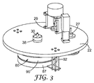
図1及び2は、本発明の方法に有用である、円筒型RIE装置を図示する。プラズマ生成及びイオン加速のための一般的な要素は、10として一般に示されている。このRIE装置10は、支持構造体12と、1つ以上のドア18の前側パネル16を含むハウジング14と、1つ以上の区画に分けられた内側チャンバ24をその中に画定する側壁20及び後側プレート22と、回転可能にチャンバ内に取り付けられたドラム26と、回転可能にチャンバ内に取り付けられ、全体として28として参照される複数のリール機構と、ドラム26を回転可能に駆動させるための駆動機構37と、チャンバ内に回転可能に取り付けられたアイドラーローラー32と、チャンバに流体連通した真空ポンプ34と、を含む。
1 and 2 illustrate a cylindrical RIE apparatus that is useful in the method of the present invention. A common factor for plasma generation and ion acceleration is generally indicated as 10. The
支持構造体12は、この場合では、垂直に直立した方式で、ハウジング14を望ましい構成で支持するための、当該技術分野において既知の任意の手段である。図1及び図2で示されるように、ハウジング14は、以下でより詳細に記載されるように2部のハウジングであってもよい。本実施形態では、支持構造体12は、装置10を支持するための2部のハウジングのそれぞれの側に取り付けられるクロス支持体40を含む。特に、クロス支持体40は、装置10をそれぞれ移動させ、支持するための、ホイール42及び調整可能なフィート44の両方を含む。図1及び2に示される実施形態では、クロス支持体40は、アタッチメント支持体46を介して、ハウジング14のそれぞれの側に取り付けられる。特に、クロス支持体40は、側壁20の1つに、すなわち底部の側壁に、アタッチメント支持体46を介して接続され、一方でハウジング14の他方の側上のクロス支持体40は、アタッチメント支持体46によって後側プレート22に接続される。更なるクロスバー47が、図1に示されるように装置10の右側にクロス支持体40間に供給される。これは更なる構造的強化をもたらすことができる。
The
ハウジング14は、排気、排気の後に導入されたガスの封じ込め、ガスからのプラズマ生成、イオン衝撃、及びエッチングすることができる、制御された環境を提供する任意の手段であってもよい。図1及び図2で示されている実施形態では、ハウジング14は前側パネル16、4つの側壁20、及び後側プレート22を含む外壁を有する。外壁は、チャンバ24と示される中空の内部を備える箱を画定する。側壁20及び後側プレート22は、当該技術分野において既知の任意の方法で一緒に締結され、側壁20及び後側プレート22を、チャンバ24の排気、プラズマ生成のための流体の封じ込め、プラズマ生成、イオン加速、及びエッチングを可能にするのに十分な方法で、互いに厳密に固定される。前側パネル16は、基材材料の搭載及び除荷のため及びメンテナンス実施のためのチャンバ24へのアクセスを提供するように、固定されていない。前側パネル16は、ヒンジ50(又は同等な接続手段)を介して、一対のドア18を画定する側壁20のうちの1つに接続される2つのプレートに分離される。これらのドアは、好ましくは、真空封止の使用によって(例えば、Oリング)側壁20の縁部に封止する。ロック機構52は選択的にドア18を側壁20に固定し、チャンバ24の排気、プラズマ生成のための流体の保管、プラズマ生成、イオン衝撃、及びエッチングを可能にする方法で、ドア18を壁20に固定することができる任意の機構であってもよい。
The housing 14 may be any means that provides a controlled environment that can be evacuated, containment of gas introduced after evacuation, plasma generation from the gas, ion bombardment, and etching. In the embodiment shown in FIGS. 1 and 2, the housing 14 has an outer wall that includes a
一実施形態では、チャンバ24は、分離壁54によって2つの区画56及び58に分離される。壁54内の経路又は穴60は、区画間の流体又は基材の経路を提供する。あるいは、チャンバは、1つの区画のみ、又は3つ以上の区画であってもよい。チャンバは1つの区画のみであることが好ましい。
In one embodiment, the
ハウジング14は、密閉可能に、ポート62を被覆し、その中で発生しているエッチングプロセスを観察することができる、高圧の、透明なポリマープレート64を備える、複数の観察ポート62を含む。ハウジング14はまた、その中で様々なセンサー(例えば、温度、圧力など)が確保され得る、複数のセンサーポート66を含む。ハウジング14は、それを介して流体が、必要に応じてチャンバ24内に導入され得る導管接続を提供するための入口ポート68を更に含む。ハウジング14はまた、ガス及び液体を送り出すか、ないしは別の方法でチャンバ24から排出することを可能にする、ポンプポート70及び72を含む。
The housing 14 includes a plurality of
ポンプ34は、側部20の1つから、好ましくは底部(図2に示されるように)から延びているように示される。ポンプ34は、ハウジング14内の制御された環境に流体連通される、例えばターボイオンポンプであってもよい。下方のチャンバ58を排気し、その中の圧力を維持するために、他のポンプ、例えば、拡散ポンプ又は低温ポンプが使用されてもよい。エッチング工程中のプロセス圧力は、異方性エッチングを提供するために、約1ミリトール(0.133Pa)〜約20ミリトール(2.67Pa)の範囲であるように選択されるのが好ましい。摺動バルブ73は、この流体接続部に沿って配置され、ポンプ34とハウジング14の内部との間の流体連通を選択的に交差するか、又は遮断することができる。摺動バルブ73は、ポンプポート62が十分に開いて、部分的に開いて、又はポンプ34との流体連通に対して閉じているように、ポンプポート62の上を移動させることができる。
The
ドラム26は、環状表面82及び2つの平坦な端面84を備える円筒型電極80である。電極は、任意の導電性材料で作製されてもよく、好ましくは、例えばアルミニウム、銅、スチール、ステンレス鋼、銀、クロム、又はこれらの合金である。好ましくは、製造の容易さ、低スパッタ収率、及び低コストから、電極はアルミニウムである。
The
ドラム26は、電界が外側に浸透できるようにする、コーティングされていない導電性の領域と、並びに、電界の浸透を防ぐための非導電性の絶縁領域とを含むよう、ひいては電極の非絶縁性若しくは導電性部分への薄膜のコーティングを制限するように更に作製されてもよい。非導電性材料は典型的に絶縁体、例えばポリマー(例えば、ポリテトラフルオロエチレン)である。導電性領域として小さなチャンネルのみ(典型的にはコーティングされるべき、透明な、導電性オキシド基材の幅)を提供するように、この非導電性であるという目的を満たす様々な実施形態は、当業者であれば想定し得る。
The
図1は、ドラム26の実施形態を示し、コーティングされないまま残り、したがって導電性である環状表面82内の環状チャネル90を除き、ドラム26の環状表面82及び端面84は、非導電性又は絶縁性材料でコーティングされている。更に、暗部シールド86及び88の対は環状表面82上の絶縁材料を被覆し、一部の実施形態では端面84を被覆する。絶縁性材料は、それに沿ってプラズマ生成及び負バイアスが発生し得る電極の表面を限定する。しかしながら、絶縁性材料は、ときにはイオン衝撃によって汚染されるため、暗部シールド86及び88は、絶縁材料の部分又はすべてを被覆してもよい。これらの暗部シールドは、アルミニウムなどの金属から作製されてもよいが、これらは、絶縁材料(図示せず)の手段によって電極から分離されているので、導電性作用物質として作用しない。これにより、電極へのプラズマの封じ込めが可能になる。
FIG. 1 illustrates an embodiment of the
ドラム26の別の実施形態は、図3及び図4に示されており、ここではドラム26は、ドラム26の環状表面82に取り付けられた、一対の絶縁性リング85及び87を含む。一部の実施形態では、絶縁性リング87は、端面84を被覆するようにも作用するキャップである。ボルト92は、平坦なプレート又はストラップとして具体化された支持手段94を後側プレート22に固定する。ボルト92及び支持手段94は、ドラム26の様々な部分を支持するよう補助することができる。一対の絶縁性リング85及び87は、環状表面82に取り付けられると、チャネル90として具体化された、露出した電極部分を画定する。
Another embodiment of the
透明の、導電性オキシド基材が電極と接触する箇所(すなわち、電極のプラズマ暗部限界に接触する、又は電極のプラズマ暗部限界内の(例えば、約3mm))を除き、電極80は、すべての領域において絶縁性材料によって、何らかの方法で被覆される。この被覆により、透明の導電性オキシド基材と密接させることができる電極の露出部分が画定される。電極の残部は、絶縁性材料によって被覆される。電極が通電され、得られるプラズマに対して負にバイアスされたとき、この比較的厚い絶縁性材料は、絶縁性材料が被覆している表面上のエッチングを防ぐ。結果として、エッチングは、被覆されていない領域(すなわち、絶縁性材料で被覆されていない領域、チャンネル90)に限定され、被覆されていない領域は、好ましくは、比較的薄い透明な導電性オキシド基材によって被覆されている。
Except where the transparent, conductive oxide substrate contacts the electrode (ie, contacts the electrode's plasma dark limit or within the electrode's plasma dark limit (eg, about 3 mm)), the
図1及び図2を参照すると、ドラム26は、磁性流体貫通(ferrofluidic feedthrough)、及び後側プレート22における穴の中に固定される回転継手(rotary union)38(又は同等の機構)を介して後側プレート22に取り付けられる。磁性流体貫通及び回転継手は、真空封止を保持しながら、標準的な冷却流体導管及び電気ワイヤから、回転中の回転可能ドラム26の、中空の冷却剤経路及び導電電極それぞれへ、別個の流体及び電気的接続を提供する。回転継手はまた、必要な応力を供給して、ドラムを回転させ、この応力は、ブラシレスDCサーボモーターなど、任意の駆動手段から供給される。しかしながら、後側プレート22並びに導管及びワイヤへのドラム26の接続は、そのような接続を供給することができ、かつ磁性流体貫通及び回転継手に制限されないような任意の手段によって実施されてもよい。このような磁性流体貫通及び回転継手の一例は、Ferrofluidics Co.(Nashua,NH)製の、内径約2インチ(5cm)の中空シャフトフィードスルーである。
With reference to FIGS. 1 and 2, the
ドラム26は、駆動アセンブリ37によって回転可能に駆動され、これは回転運動をドラム26に転換できる任意の機械的及び/又は電気的システムであってもよい。図2に示される一実施形態では、駆動アセンブリ37は、ドラム26に硬く接続されている駆動プーリー39に機械的に接続されている駆動プーリー31で終端する駆動シャフトを備える、モーター33を含む。ベルト35(又は同等の構造体)は、駆動プーリー31からの回転運動を駆動プーリー39に転換する。
The
複数のリール機構28が、後側プレート22に回転可能に取り付けられる。複数のリール機構28は、一対の基材スプール28A及び28Bを備える基材リール機構を含み、一部の実施形態では、一対のスペーシングウェブスプール28C及び28Dを備えるスペーシングウェブリール機構を備える、スペーシングウェブリールと、一対のマスキングウェブスプール28E及び28Fを備えるマスキングウェブリール機構を含み、ここではそれぞれの対は、送達スプールを1つ及び巻取りスプールを1つ含む。図2で明らかなように、少なくとも各巻取りリール28B、28D、及び28Fは、エッチング中に、必要に応じて、リールを選択的に回転させる回転応力を供給するための、これに機械的に接続された駆動機構27(例えば、以下に記載のように標準モーター)を含む。更に、選択された実施形態における各送達リール28A、28C、及び28Eは、ウェブ及び/又は駆動機構29に緊張をもたらすためのテンショナーを含む。
A plurality of
各リール機構は、送達及び巻取りスプールを含み、これらのスプールは、互いに同一又は異なる区画内にあってもよく、次いで電極内の同じ区画にあってもよく、あるいはそうでなくてもよい。各スプールは、溝を画定しながら、それぞれの端部から半径方向に延びる、軸方向のロッド及びリムを備える標準的な構造体であり、そこでは、細長い部材(この場合では基材又はウェブ又はウェブ)が巻かれる又は巻き付けられる。各スプールは、後側プレート22を通じて延びる回転可能なステムに密封可能に固定して取り付けられる。スプールが駆動される場合では、ステムはモーター27(例えば、ブラシレスDCサーボモーター)に機械的に接続される。非駆動スプールの場合では、スプールは単に回転可能な方式で、駆動機構29を介して、後側プレート22に連結され、また、ゆるみを防ぐために伸張機構を含んでもよい。
Each reel mechanism includes a delivery and take-up spool that may be in the same or different compartments from each other and then in the same compartment in the electrode or not. Each spool is a standard structure with axial rods and rims extending radially from respective ends while defining a groove, where an elongated member (in this case a substrate or web or Web) is wound or wound. Each spool is sealingly fixedly attached to a rotatable stem extending through the
RIE装置10はまた、チャンバ内で回転可能に取り付けられるアイドラーローラー32と、このチャンバに流体接続するポンプ34と、を含む。アイドラーローラーは、ドラム26上で基材スプール28Aからチャネル90まで、かつチャネル90から巻取り基材スプール28Bまで基材を案内する。更に、スペーシングウェブ及びマスキングウェブが使用され、アイドラーローラー32は、これらのウェブ及び基材を、基材スプール28A及びマスキングウェブスプール28Eからチャネル90に、並びにチャネル90から巻取り基材スプール28B及び巻取りマスキングウェブスプール28Fにそれぞれ案内する。
The
RIE装置10は、磁性流体貫通38を介して、温度制御液を電極80に供給するための温度制御システムを更に含む。温度制御システムは、装置10上に供給されてもよく、又は別の方法としては、別個のシステムから供給されて、温度制御液が、電極80内の経路と流体接続している限り、導管を介して、装置10に送り出されてもよい。温度制御システムは、エッチングのための正確な温度の電極を供給するために必要とされる場合、電極80を加熱するか、又は冷却してもよい。好ましい実施形態では、温度制御システムは、冷却材(例えば、水、エチレングリコール、クロロフルオロカーボン、ハイドロフルオロエーテル、及び液化ガス(例えば液体窒素))を使用する冷却システムである。
The
RIE装置10はまた、排気ポート70に流体的に接続された排気ポンプを含む。このポンプはチャンバを排気させることができる、任意の真空ポンプ、例えばルーツ式送風機、ターボ分子ポンプ、拡散ポンプ、低温ポンプであってもよい。更に、このポンプは機械式ポンプによって補助又はバックアップされてもよい。排気ポンプは、装置10上に供給されてもよく、又は別の方法としてあるいは、別個のシステムとして供給され、チャンバに流体接続されてもよい。
The
RIE装置10はまた、薄膜を作製するのに使用される流体を制御する、好ましくはマスフローコントローラーの形態の、流体フィーダーを含み、この流体はチャンバ内に、その排気後に送られる。フィーダーは、装置10上に供給されてもよく、又は別の方法として、別個のシステムとして供給され、チャンバに流体接続されてもよい。フィーダーは、エッチング中に、正確な容積率又は質量流量の流体をチャンバに供給する。エッチングガスは、酸素、アルゴン、塩素、フッ素、炭素、四フッ化物、四塩化炭素、ペルフルオロメタン、ペルフルオロエタン、ペルフルオロプロパン、三フッ化窒素、六フッ化硫黄、メタンを含むことができる。ガスの混合物は、エッチングプロセスを促進するために有利に使用されてもよい。
The
RIE装置10はまた、電気端子30を介して、電極80に電気的に接続された電源を含む。電源は、装置10上に供給されてもよく、又は別の方法として、別個のシステム上に供給されて、電気端子(図2に示されるように)を介して電極に電気的に接続されてもよい。いずれの場合においても、電源は、十分な電力を供給することができる任意の発電又は送電システムである。(以下の記載を参照。)。
The
様々な電源が可能であるが、RF電力が好ましい。これは、自己バイアスを、適切に構成された通電された電極上に形成するのに、周波数は十分高いが、得られるプラズマに定在波を作るには十分高くないためである。RF電力は、高出力(幅の広いウェブ又は基材、急速なウェブ速度)に対して測定可能である。RF電力が使用されるとき、電極上の負バイアスは、負自己バイアスであり、すなわち電極上に負バイアスを誘発するために使用される、別個の電源は必要ない。RF電力が好ましいため、本記載の残りはそのことについてのみ焦点を当てる。 Various power sources are possible, but RF power is preferred. This is because the frequency is high enough to form a self-bias on a properly configured energized electrode, but not high enough to create a standing wave in the resulting plasma. RF power can be measured for high power (wide web or substrate, rapid web speed). When RF power is used, the negative bias on the electrode is a negative self-bias, i.e., no separate power supply is needed, which is used to induce a negative bias on the electrode. Since RF power is preferred, the remainder of this description will focus only on that.
RF電源は、電極80を、0.01〜50MHz、好ましくは13.56MHzの範囲で、又は任意の、その数倍(例えば1、2、又は3倍)の範囲の周波数で通電する。このRF電力は電極80に供給されると、チャンバ内のガスからプラズマを作る。RF電源は、同軸送電線を通じて効果的にRF電力を送電するように、電力供給のインピーダンスが、送電線のインピーダンス(通常は50オーム抵抗)と一致するように働くネットワークを介して、電極に接続された13.56MHz発振器などのRF発生装置であってもよい。
The RF power supply energizes the
RF電力を電極に適用すると、プラズマが確立される。15のRFプラズマでは、通電した電極は、プラズマに対して負バイアスとなる。このバイアスは一般的に、500ボルト〜1400ボルトの範囲である。このバイアスはプラズマ内のイオンを電極80に向けて加速させる。加速するイオンは、以下により詳細に記載されるように、電極80と接触する。
When RF power is applied to the electrodes, a plasma is established. In the 15 RF plasma, the energized electrode is negatively biased with respect to the plasma. This bias is typically in the range of 500 volts to 1400 volts. This bias accelerates ions in the plasma toward the
操作時に、エッチングがその上に望ましい基材の全体スプールが、スプール28Aとしてステムの上に挿入される。図1及び図2では、スプールは下方の区画58に配置されており、一方で、エッチングは上方の区画56で生じているため、これらのスプールへのアクセスは下方のドア18を通じて供給される。更に、エッチングが生じた後に、巻取りスプールとして機能するように、空のスプールが、スプール28Bとして、スプールを保持する基材と反対側で締結される。
In operation, the entire spool of substrate over which etching is desired is inserted over the stem as
スペーサーウェブが、巻き付け又は巻き出し中に基材を弛緩させるために必要とされており、スペーサーウェブ送達及び/又は巻取りスプールは、スプール28C及び28Dとして供給されてもよい(図中に示される特定の場所内のスプールの位置は問題ではない)。同様に、エッチングが、パターン、あるいは部分的な方式で必要とされる場合に、マスキングウェブが、スプール28Eとして入力スプール上に配置され、空のスプールが、スプール28Fとして巻取りスプールとして配置される。
A spacer web is required to relax the substrate during winding or unwinding, and the spacer web delivery and / or take-up spool may be supplied as
基材若しくはウェブを備えたスプール、及びこれらを備えないスプールのすべてが配置された後、その上でエッチングが生じる基材は、織られるか、あるいは巻取りリールにシステムを介して引っ張られる。スペーサーウェブは概して、システムを介して織られていないが、代わりに、この工程のちょうど前及び/又はこの工程がちょうど供給された後に、基材から分離される。基材は特に、チャネル90における電極80の周辺に巻き付けられ、したがって、露出した電極部分を被覆する。基材は、十分に張って電極と接触した状態のままであり、かつ基材の長さが常に、エッチングのために電極と接触しているように、電極が回転するにつれて、電極と共に移動する。これは、基材が、ロールの一方の端部から他方へと連続プロセスにおいてエッチングされるのを可能にする。基材は、エッチングのために定置され、下方のドア18は密閉される。
After all of the spools with and without the substrate or web have been placed, the substrate on which etching occurs is woven or pulled through the system to the take-up reel. The spacer web is generally not woven through the system, but instead is separated from the substrate just before this step and / or just after this step is fed. The substrate is especially wrapped around the
チャンバ24は、すべての空気及び他の不純物を取り除くために排気される。いったんエッチャントガス混合物が、排気されたチャンバ内に送られると、装置は、エッチングプロセスを開始する準備が整う。RF電源は、電極80にRF電界を供給するために活性化される。このRF電界は、ガスをイオン化させ、その中で、結果としてイオンとプラズマの形成が得られる。これは特に、13.56MHz発信器を使用して作られるが、他のRF源及び周波数範囲が使用されてもよい。
The
いったんプラズマが作られると、RF電力で電極を通電し続けることによって、負DCバイアス電圧が電極80上に作られる。このバイアスは、電極80のチャネル90(非絶縁電極部分)に向けてイオンを加速させる(電極の残部は絶縁されているか、シールドされているかのいずれかである)。イオンは、マトリックス材料を(分散相に対して)、電極80のチャネル90と接触する基材の長さにおいて選択的にエッチングし、基材のその長さ上のマトリックス材料の異方性エッチングを生じさせる。
Once the plasma is created, a negative DC bias voltage is created on
連続エッチングに関して、基材及び任意のマスキングウェブを、上方区画56を通じて、かつ電極80の上で引っ張るように、巻取りスプールが駆動され、よってマトリックスのエッチングは、環状チャネル90と接触する、任意のマスキングされていない基材部分上で発生する。基材はしたがって、上方区画を通じて連続的に引っ張られ、同時に連続的なRF場が電極上に配置され、十分な反応性ガスがチャンバ内に存在する。結果は、細長い基材上及び実質的に基材上のみの連続的エッチングである。エッチングは、電極の絶縁された部分上に発生しなければ、チャンバの他の箇所でも発生しない。プラズマに供給された有効電力が、円筒型電極の末端部プレートにおいて消散するのを防ぐために、接地された暗部シールド86及び88が使用されてもよい。暗部シールド86及び88は、潜在的な汚染の低減に貢献する、任意の形状、寸法、及び材料であってもよい。図1及び2に示される実施形態では、暗部シールド86及び88は、ドラム26の上及びその上の絶縁体上でフィットする金属リングである。暗部シールド86及び88は、暗部シールド86及び88がドラム26に接触する領域において、ドラム26を被覆する絶縁材料のために、バイアスしない。このリング様の実施形態における暗部シールドは、非環状方式で、ドラム26から離れて延びるその各端部上のタブを更に含む。これらのタブは、チャネル90内で基材を位置合わせするのに役立つことができる。
For continuous etching, the take-up spool is driven to pull the substrate and any masking web through the
好ましくは、温度制御システムは、流体を電極80を通じてプロセス全体で、送り出し、電極を望ましい温度に維持する。典型的に、これは前述のように、冷却材を用いて電極を冷却することを伴うが、一部では、加熱が望ましい場合がある。更に、基材は、電極と直接接触しているため、プラズマから基材への熱移動は、この冷却システムを介して管理されることより、温度に敏感である薄膜のコーティング、例えばポリエチレンテレフタレート、ポリエチレンナフタレートなどのコーティングを可能にする。
Preferably, the temperature control system delivers fluid through the
エッチングプロセスの完了後、スプールは、壁にそれらを支持しているシャフトからはずされてもよい。ナノ構造化物品をその中に備える基材は、スプール28B上にあり、使用のための準備が整っている。
After completion of the etching process, the spools may be removed from the shaft that supports them on the wall. The substrate with the nanostructured article therein is on
本明細書に記載されるナノ構造化物品の一部の実施形態では、ナノ構造化物品は追加の層を含む。例えば、物品は追加のフルオロケミカル層を含んで、この物品に改善された撥水及び/又は撥油特性を付与してもよい。ナノ構造化表面を、後処理してもよい(例えば、追加のプラズマ処理など)。プラズマ後処理は、ナノ構造体上に存在し得る化学官能基を変更するために、又はナノ構造体の性能を向上させる薄膜の堆積のために、表面改質を含んでもよい。表面改質は、メチル、フッ化物、ヒドロキシル、カルボニル、カルボキシル、シラノール、アミン、又は他の官能基の結合を含んでよい。堆積した薄膜は、フルオロカーボン、ガラス様、ダイヤモンド様、オキシド、炭化物、窒化物、又は他の物質を含んでもよい。表面改質処理が適用される場合、異方性にエッチングされたナノ構造化表面の大きな表面積により、表面官能基の密度は高くなる。アミン官能基が使用される場合、抗体、タンパク質、酵素などの生物学的薬剤は、アミン官能基に容易にグラフトされ得る。シラノール官能基が使用される場合、シラン基の密度が高いことから、シラン化学物質はナノ構造化表面に容易に適用され得る。シランの化学的性質に基づく抗菌、洗浄容易、及び耐汚染表面処理は、市販されている。抗菌性処理は、シラン末端基を備える第四級アンモニウム化合物を含んでもよい。易洗浄性化合物としては、ペルフルオロポリエーテルシラン、ヘキサフルオロプロピレンオキシド(HFPO)シランなどのフルオロカーボン処理剤を挙げることができる。耐汚染処理は、ポリエチレングリコールシランを含んでもよい。薄膜が使用されるとき、これらの薄膜は更なる耐久性をナノ構造体に提供することができ、又は薄膜の屈折率に応じて固有の光学効果を提供することができる。特定のタイプの薄膜は、ダイヤモンド様カーボン(DLC)、ダイヤモンド様ガラス(DLG)、アモルファスシリコン、窒化ケイ素、プラズマ重合シリコーン油、アルミニウム、銅を含んでもよい。 In some embodiments of the nanostructured articles described herein, the nanostructured article includes an additional layer. For example, the article may include an additional fluorochemical layer to impart improved water and / or oil repellency properties to the article. The nanostructured surface may be post-treated (eg, additional plasma treatment, etc.). Plasma post-treatment may include surface modification to alter chemical functional groups that may be present on the nanostructure or to deposit a thin film that improves the performance of the nanostructure. Surface modification may include the attachment of methyl, fluoride, hydroxyl, carbonyl, carboxyl, silanol, amine, or other functional groups. The deposited thin film may include fluorocarbon, glass-like, diamond-like, oxide, carbide, nitride, or other material. When surface modification is applied, the density of surface functional groups increases due to the large surface area of the anisotropically etched nanostructured surface. When amine functional groups are used, biological agents such as antibodies, proteins, enzymes, etc. can be easily grafted onto the amine functional group. When silanol functional groups are used, silane chemicals can be easily applied to nanostructured surfaces because of the high density of silane groups. Antibacterial, easy to clean, and antifouling surface treatments based on silane chemistry are commercially available. The antibacterial treatment may include a quaternary ammonium compound with a silane end group. Examples of easily washable compounds include fluorocarbon treating agents such as perfluoropolyether silane and hexafluoropropylene oxide (HFPO) silane. The anti-contamination treatment may include polyethylene glycol silane. When thin films are used, these thin films can provide additional durability to the nanostructure or can provide inherent optical effects depending on the refractive index of the thin film. Certain types of thin films may include diamond-like carbon (DLC), diamond-like glass (DLG), amorphous silicon, silicon nitride, plasma polymerized silicone oil, aluminum, copper.
本明細書に記載のナノ構造化物品は、反射防止特性、光吸収特性、防曇特性、改善された接着力及び耐久性などの、1つ以上の望ましい特性を示し得る。 The nanostructured articles described herein may exhibit one or more desirable properties such as antireflective properties, light absorption properties, antifogging properties, improved adhesion and durability.
例えば、一部の実施形態では、ナノ構造化異方性表面の表面反射率は、非処理表面の表面反射率の約50%以下である。表面特性の比較に関して本明細書で使用されるとき、用語「非処理表面」は、(比較されることになる本発明のナノ構造化表面と)同じマトリックス材料及び同じナノ構造化異方性表面を含むが、ナノ構造化異方性表面は含まない物品の表面を意味する。 For example, in some embodiments, the surface reflectance of the nanostructured anisotropic surface is no more than about 50% of the surface reflectance of the untreated surface. As used herein with respect to the comparison of surface properties, the term “untreated surface” refers to the same matrix material and the same nanostructured anisotropic surface (as the nanostructured surface of the invention to be compared). Means the surface of the article including but not including the nanostructured anisotropic surface.
一部の実施形態は、ナノ構造化異方性表面に取り付けられた、例えばインク、封入剤、接着剤、若しくは金属を含む層又はコーティングを更に含む。層又はコーティングは、非処理表面よりも、本発明のナノ構造化異方性表面への接着性が改善され得る。 Some embodiments further comprise a layer or coating comprising, for example, ink, encapsulant, adhesive, or metal attached to the nanostructured anisotropic surface. The layer or coating may have improved adhesion to the nanostructured anisotropic surface of the present invention over an untreated surface.
本明細書に記載の複合体は、電磁遮蔽、透明な電気回路/アンテナ、タッチパネル、太陽電池及びフラットパネルディスプレイなどの光電子デバイスの透明な導通電極、自動車窓の表面ヒーター、低反射窓、エレクトロクロミック窓、カメラレンズ、鏡、及び静電気消散、並びにビルディング、街灯及び太陽熱収集器用の透明な熱反射窓材料を含む、様々な用途に有用である。 The composites described herein include: transparent conducting electrodes for optoelectronic devices such as electromagnetic shielding, transparent electrical circuits / antennas, touch panels, solar cells and flat panel displays, automotive window surface heaters, low reflection windows, electrochromic Useful for a variety of applications, including windows, camera lenses, mirrors, and static dissipation, and transparent heat reflective window materials for buildings, street lights and solar collectors.
図5は、本明細書に開示される反射防止物品を使用する、例えばLCDなどの、例示のディスプレイ100の概略断面図を示す。一実施形態では、複合体102は、基材の第一表面上に配置された反射防止層106と、基材の第二表面上に配置された光学的に透明な接着剤108を備える、対向する第一表面及び第二表面を有する透明な導電性オキシドをコーティングされた基材104を含む。所望により光学的に透明な接着剤を保護するために、剥離ライナー(図示せず)を使用してもよく、加工及び保管中に反射防止コーティングを保護するためにプレマスク(同様に図示せず)を使用してもよい。光学的に透明な接着剤がガラス基材に直接接触するように、複合体102は次いでガラス基材110に積層され、このガラス基材は次いで典型的にはエアギャップ114が反射防止コーティングと液晶モジュールとの間に配置された状態で、液晶モジュール112へと組み立てられる。
FIG. 5 shows a schematic cross-sectional view of an
本開示に使用され得る光学的に透明な接着剤は、光学的に透明な接着剤のヘイズ及び透過率試験の実施例の項で、以下に記載されている内容において、25μm厚のサンプルで測定されたとき、少なくとも約90%、又は更に高い光学透過率と、約5%以下、又は約5%より更に低いヘイズ値を呈するものである。適した光学的に透明な接着剤は、帯電防止特性を有してもよく、腐食感受性の層と適合性があってもよく、接着剤を延伸することによって基材から剥離することができてもよい。例示的な光学的に透明な接着剤としては、帯電防止性の光学的に透明な感圧接着剤に関する国際公開第2008/128073号(Everaerts et al.)に記載のもの;伸長剥離する光学的に透明な接着剤に関する米国特許出願公開第2009/0229732(A1)号(Determan et al.)に記載のもの;酸化インジウムスズと相溶性の光学的に透明な接着剤に関する米国特許出願公開2009/0087629号(Everaerts et al.)に記載のもの;光学的に透過性の接着剤を有する帯電防止性の光学的な構成体に関する米国特許出願第12/181,667号(Everaerts et al.)に記載のもの;腐食感受性層と適合性のある接着剤に関する米国特許出願第12/538,948号(Everaerts et al.)に記載のもの;光学的に透明な、伸長剥離する接着剤テープに関する米国特許仮出願第61/036,501号(Hamerski et al.)に記載のもの;及び米国仮出願特許第61/141,767号(Hamerski et al.)の伸長剥離型接着テープに記載のものなどの、例示的な光学的に透明な接着剤に記載されるものが挙げられる。一実施形態では、光学的に透明な接着剤は、約5マイクロメートル以下の厚さを有する。 The optically clear adhesive that can be used in the present disclosure is measured in a 25 μm thick sample, as described below, in the Example section of the optically clear adhesive haze and transmission test. When present, it exhibits an optical transmission of at least about 90% or higher and a haze value of about 5% or lower, or even lower than about 5%. Suitable optically clear adhesives may have antistatic properties, may be compatible with corrosion sensitive layers, and can be peeled from the substrate by stretching the adhesive. Also good. Exemplary optically clear adhesives include those described in WO 2008/128073 (Everaerts et al.) Relating to antistatic optically transparent pressure sensitive adhesives; US Patent Application Publication No. 2009/0229732 (A1) (Determan et al.) Relating to highly transparent adhesives; US Patent Application Publication No. 2009/2009 concerning optically transparent adhesives compatible with indium tin oxide No. 0087629 (Everaerts et al.); In US patent application Ser. No. 12 / 181,667 (Everaerts et al.) Relating to an antistatic optical construction with an optically transparent adhesive. US patent application Ser. No. 12/538, relating to adhesives compatible with corrosion-sensitive layers No. 948 (Everaerts et al.); U.S. Provisional Application No. 61 / 036,501 (Hamerski et al.) Relating to an optically clear, stretch-release adhesive tape; Examples described in exemplary optically clear adhesives include those described in the stretch release adhesive tape of provisional application 61 / 141,767 (Hamerski et al.). In one embodiment, the optically clear adhesive has a thickness of about 5 micrometers or less.
一部の実施形態では、本明細書に記載のナノ構造化物品は、マルチ(メタ)アクリレート、ポリエステル、エポキシ、フルオロポリマー、ウレタン、又はシロキサン(これらのブレンド又はコポリマーを包含する)のうちの少なくとも1つを含む架橋可能なマトリックスに分散させた、SiO2ナノ粒子又はZrO2ナノ粒子を少なくとも1つ含む、ハードコートを更に含む。市販の液体樹脂系材料(典型的には「ハードコート」として呼ばれる)は、マトリックスとして使用することができ、又はマトリックス成分として使用することができる。このような材料としては、California Hardcoating Co.(San Diego,CA)から商品名「PERMANEW」で市販されているもの;及びMomentive Performance Materials(Albany,NY)から商品名「UVHC」で市販されているものが挙げられる。加えて、Nanoresins AG(Geesthacht Germany)から商品名「NANOCRYL」及び「NANOPOX」で入手可能なものなどの、ナノ粒子を充填された市販のマトリックスを使用することもできる。 In some embodiments, the nanostructured article described herein comprises at least one of multi (meth) acrylate, polyester, epoxy, fluoropolymer, urethane, or siloxane (including blends or copolymers thereof). dispersed in crosslinkable matrix containing one, it comprises at least one of SiO 2 nanoparticles or ZrO 2 nanoparticles, further comprises a hard coat. Commercially available liquid resin-based materials (typically referred to as “hard coats”) can be used as a matrix or can be used as a matrix component. Such materials include California Hardcoating Co. (San Diego, Calif.) Commercially available under the trade name “PERMANEW”; and Momentive Performance Materials (Albany, NY) commercially available under the trade name “UVHC”. In addition, commercially available matrices filled with nanoparticles, such as those available from Nanoresins AG (Geestacht Germany) under the trade names “NANOCRYL” and “NANOPOX” can also be used.
加えて、東レフィルム加工株式会社(東京,日本)から商品名「THS」で入手可能なもの;リンテック株式会社(東京,日本)から商品名「FPD用OPTERIAハードコートフィルム」で入手可能なもの;ソニーケミカル&インフォメーションデバイス(東京,日本)から入手可能な商品名「SONY光学薄膜」で入手可能なもの;SKC Haas(Seoul,Korea)から商品名「HARDCOATED FILM」で入手可能なもの;及びTekra Corp.(Milwaukee,WI)から商品名「TERRAPPIN G FILM」で入手可能なものなどの、ハードコート薄膜を含有しているナノ粒子は、マトリックス又はマトリックス成分として使用することもできる。 In addition, those available under the trade name “THS” from Toray Film Processing Co., Ltd. (Tokyo, Japan); those available under the trade name “OPTERIA hard coat film for FPD” from Lintec Corporation (Tokyo, Japan) Available under the trade name “SONY Optical Thin Film” available from Sony Chemical & Information Devices (Tokyo, Japan); available under the trade name “HARDCOATED FILM” from SKC Haas (Seoul, Korea); and Tekra Corp. . Nanoparticles containing a hard-coated thin film, such as those available under the trade designation “TERRAPPPIN G FILM” from (Milwaukee, Wis.) Can also be used as a matrix or matrix component.
1つの例示的なプロセスでは、液体形態で提供されるハードコートは、透明な導電性酸化物(TCO)をコーティングした基材の第一表面上にコーティングされる。ハードコートの化学的性質に応じて、硬化又は乾燥させて、基材上に乾燥させたAR層を形成する。ハードコートをコーティングした透明で導電性のオキシド(TCO)をコーティングした基材を、次いで、(一つの例示的な方法では、図1に記載の装置を使用して)上記の反応性イオンエッチング(RIE)プロセスを用い、加工する。上記の反射防止特性及び防曇特性を含む、望ましい特性を呈することに加えて、RIEプロセスはまた、イリデッセンス(「干渉縞」とも呼ばれる)の望ましくない現象も低減する。機能層とハードコート層との屈折率の差は、ハードコート層に入射する外部の光が反射した場合に生じる、虹様の色を生成するイリデッセンス(iridescence)の現象を生じさせる場合がある。イリデッセンスは、ディスプレイ上の画像を妨害するため、ディスプレイ用途において非常に望ましくない。 In one exemplary process, a hard coat provided in liquid form is coated on a first surface of a substrate coated with a transparent conductive oxide (TCO). Depending on the chemistry of the hard coat, it is cured or dried to form a dried AR layer on the substrate. The substrate coated with a transparent, conductive oxide (TCO) coated with a hard coat is then subjected to the reactive ion etching (in one exemplary method, using the apparatus described in FIG. 1) ( RIE) process. In addition to exhibiting desirable properties, including the anti-reflective and anti-fogging properties described above, the RIE process also reduces undesirable phenomena of iridescence (also referred to as “interference fringes”). The difference in refractive index between the functional layer and the hard coat layer may cause the phenomenon of iridescence that produces a rainbow-like color that occurs when external light incident on the hard coat layer is reflected. Iridescence is highly undesirable in display applications because it interferes with the image on the display.
一部の当業者は、機能層とコーティング配合物との間の屈折率を一致させることによってイリデッセンスに対処しようと試みているが、反射防止と1/4波長の多層コーティングを備えるイリデッセンスの間でバランスのとれた性能を提供することは非常に難しい。本開示の一部の実施形態では、RIEプロセスは、ナノ粒子を充填したハードコートでコーティングされた、透明な導電性酸化物(TCO)によりコーティングされた基材の、エアフロント面の境界面からの反射を低減することができ、これは次いでイリデッセンスを低減し、優れた反射防止特性及び最小のイリデッセンスを呈する層を達成する。この開示の他の実施形態において、ナノ粒子(例えば、ZrO2ナノ粒子)は、ハードコートのコーティングマトリックスの屈折率を、機能層の屈折率と実質的に一致させるように調節するために使用することができる。本明細書に開示される、RIEプロセスの後の得られるコーティングされた物品は、優れた反射防止特性及び最小のイリデッセンスを呈する。 Some skilled in the art have attempted to address iridescence by matching the refractive index between the functional layer and the coating formulation, but between iridescence with antireflection and quarter wavelength multilayer coatings. Providing balanced performance is very difficult. In some embodiments of the present disclosure, the RIE process is performed from the interface of the air front surface of a substrate coated with a transparent conductive oxide (TCO) coated with a hard coat filled with nanoparticles. Reflection, which in turn reduces iridescence and achieves a layer that exhibits excellent anti-reflection properties and minimal iridescence. In other embodiments of this disclosure, nanoparticles (eg, ZrO 2 nanoparticles) are used to adjust the refractive index of the hardcoat coating matrix to substantially match the refractive index of the functional layer. be able to. The resulting coated articles disclosed herein after the RIE process exhibit excellent anti-reflective properties and minimal iridescence.
他の実施形態では、ナノ分散相を、プラズマを用いてエッチングすることでナノ構造化(又はナノ多孔)表面を作製することができる。本方法は、本質的に上記のように、平坦なRIE又は円筒型RIEを使用して実施することができるが、マトリックスよりはむしろ、ナノ分散相のエッチングを好む選択的なエッチングを使用している(すなわち、マトリックス材料よりはむしろ、分散相材料をエッチングするガスを選択することによる)。 In other embodiments, the nanodispersed phase can be etched using plasma to create a nanostructured (or nanoporous) surface. The method can be performed using flat RIE or cylindrical RIE, essentially as described above, but using selective etching that favors nanodispersed phase etching rather than matrix. (Ie, by selecting a gas that etches the dispersed phase material rather than the matrix material).
例示的な実施形態
1.複合体であって、
概して向かい合う及び第二の主表面を有する基材;
概して向かい合う第一及び第二主表面を有する第一機能層、ここで、第一機能層の第一主表面は、基材の第一主表面上に配置され、かつ第一機能層は透明な導電層又はガスバリア層のうちの少なくとも1つである;及び
第一機能層の第二主表面上に配置された第一ナノ構造化物品;を含み、第一ナノ構造化物品が、第一マトリックス及び第一ナノスケール分散相を含み、かつ第一ランダムナノ構造化異方性表面を有する、複合体。
Exemplary Embodiments 1. A complex,
A substrate generally facing and having a second major surface;
A first functional layer having first and second major surfaces generally facing each other, wherein the first major surface of the first functional layer is disposed on the first major surface of the substrate and the first functional layer is transparent. A first nanostructured article disposed on the second major surface of the first functional layer, wherein the first nanostructured article is a first matrix And a first nanoscale dispersed phase and having a first random nanostructured anisotropic surface.
2.第一機能層がガスバリア層である、実施形態1に記載の複合体。 2. The composite according to embodiment 1, wherein the first functional layer is a gas barrier layer.
3.第一機能層が、第一の透明な導電層である、実施形態1又は2に記載の複合体。 3. The composite according to Embodiment 1 or 2, wherein the first functional layer is a first transparent conductive layer.
4.第一の透明な導電層が、パターン配置又はランダム配置されている導電材料を含む、実施形態3に記載の複合体。 4). Embodiment 4. The composite according to embodiment 3, wherein the first transparent conductive layer comprises a conductive material that is patterned or randomly arranged.
5.第一の透明な導電層が、第一の透明な導電オキシド(例えば、アルミニウムをドープした酸化亜鉛又はスズをドープした酸化インジウムのうちの1種を含む)を含む、実施形態1〜4のいずれか1つに記載の複合体。 5. Any of Embodiments 1-4, wherein the first transparent conductive layer comprises a first transparent conductive oxide (eg, including one of aluminum doped zinc oxide or tin doped indium oxide). The complex according to any one of the above.
6.第一の透明な導電層が、第一の透明な導電性金属を含む、実施形態1〜5のいずれか1つに記載の複合体。 6). Embodiment 6. A composite according to any one of Embodiments 1-5, wherein the first transparent conductive layer comprises a first transparent conductive metal.
7.第一の透明な導電層が、第一の透明な導電性ポリマーを含む、実施形態1〜6のいずれか1つに記載の複合体。 7). Embodiment 7. The composite according to any one of embodiments 1-6, wherein the first transparent conductive layer comprises a first transparent conductive polymer.
8.第一の透明な導電層がガスバリア層である、実施形態1〜7のいずれか1つに記載の複合体。 8). Embodiment 8 The composite according to any one of Embodiments 1 to 7, wherein the first transparent conductive layer is a gas barrier layer.
9.第一ナノ構造化物品が、第一ナノ構造化物品の合計体積に基づき、0.5〜41(一部の実施形態では、1〜20、又は更には2〜20)体積%の範囲で第一のナノスケール分散相を含む、実施形態1〜8のいずれか1つに記載の複合体。 9. The first nanostructured article is in the range of 0.5-41 (in some embodiments, 1-20, or even 2-20) volume percent, based on the total volume of the first nanostructured article. Embodiment 9. The composite according to any one of embodiments 1-8, comprising one nanoscale dispersed phase.
10.第一のナノスケール分散相が、SiO2ナノ粒子、ZrO2ナノ粒子、TiO2ナノ粒子、ZnOナノ粒子、Al2O3ナノ粒子、炭酸カルシウムナノ粒子、ケイ酸マグネシウムナノ粒子、酸化インジウムスズナノ粒子、アンチモン含有酸化スズナノ粒子、ポリ(テトラフルオロエチレン)ナノ粒子、又は炭素ナノ粒子のうちの少なくとも1つを含む、実施形態1〜9のいずれか1つに記載の複合体。
10. The first nanoscale dispersed phase is SiO 2 nanoparticles, ZrO 2 nanoparticles, TiO 2 nanoparticles, ZnO nanoparticles, Al 2 O 3 nanoparticles, calcium carbonate nanoparticles, magnesium silicate nanoparticles, indium tin oxide nanoparticles.
11.第一のナノスケール分散相のナノ粒子が表面改質される、実施形態10に記載の複合体。
11. Embodiment 11. The composite of
12.第一マトリックスが、架橋性材料(例えば、次の架橋性材料、マルチ(メタ)アクリレート、ポリエステル、エポキシ、フルオロポリマー、ウレタン、又はシロキサンのうちの少なくとも1つを架橋することにより製造された材料)を含む、実施形態1〜11のいずれか1つに記載の複合体。
12 The first matrix is a crosslinkable material (eg, a material produced by crosslinking at least one of the following crosslinkable materials, multi (meth) acrylates, polyesters, epoxies, fluoropolymers, urethanes, or siloxanes):
13.第一マトリックスが、熱可塑性材料(例えば、次のポリマー:ポリカーボネート、ポリ(メタ)アクリレート、ポリエステル、ナイロン、シロキサン、フルオロポリマー、ウレタン、環状オレフィンコポリマー、三酢酸セルロース、又はジアクリル酸セルロースのうちの少なくとも1つを含む)を含む、実施形態1〜12のいずれか1つに記載の複合体。 13. The first matrix is a thermoplastic material (eg, at least one of the following polymers: polycarbonate, poly (meth) acrylate, polyester, nylon, siloxane, fluoropolymer, urethane, cyclic olefin copolymer, cellulose triacetate, or cellulose diacrylate Embodiment 13. The composite according to any one of Embodiments 1 to 12, comprising 1).
14.第一ナノ構造化物品が、第一のナノ構造化異方性表面を表面上に有する第一の微細構造化表面を含む、実施形態1〜13のいずれか1つに記載の複合体。 14 Embodiment 14. The composite of any one of embodiments 1-13, wherein the first nanostructured article comprises a first microstructured surface having a first nanostructured anisotropic surface on the surface.
15.第一マトリックスが、合金又は固溶体を含む、実施形態1〜14のいずれか1つに記載の複合体。 15. Embodiment 15. The composite according to any one of embodiments 1-14, wherein the first matrix comprises an alloy or a solid solution.
16.第一ナノ構造化物品が、すべての方向において0.05未満の屈折率差を有する、実施形態1〜15のいずれか1つに記載の複合体。
16.
17.第一ナノ構造化物品と第一機能層の間に、0.5未満(一部の実施形態では、0.25未満、又は更には0.1未満)の屈折率差が存在する、実施形態1〜16のいずれか1つに記載の複合体。 17. An embodiment wherein there is a refractive index difference between the first nanostructured article and the first functional layer of less than 0.5 (in some embodiments, less than 0.25, or even less than 0.1). The complex according to any one of 1 to 16.
18.第一ナノ構造化異方性表面が、2%未満(一部の実施形態では、1.5%、1.25%、1%、0.75%若しくは0.5%未満、又は更には0.25%未満)の反射率(%)を有する、実施形態1〜17のいずれか1つに記載の複合体。 18. The first nanostructured anisotropic surface is less than 2% (in some embodiments, less than 1.5%, 1.25%, 1%, 0.75% or 0.5%, or even 0 The composite of any one of embodiments 1-17 having a reflectance (%) of less than .25%).
19.第一異方性主表面による反射が4%未満(一部の実施形態では、3%、2%、又は更には1.25%未満)である、実施形態1〜18のいずれか1つに記載の複合体。 19. In any one of Embodiments 1-18, wherein the reflection by the first anisotropic major surface is less than 4% (in some embodiments, less than 3%, 2%, or even 1.25%). The complex described.
20.マルチ(メタ)アクリレート、ポリエステル、エポキシ、フルオロポリマー、ウレタン、又はシロキサンのうちの少なくとも1つを含む架橋性マトリックスに分散された、SiO2ナノ粒子又はZrO2ナノ粒子のうちの少なくとも1つを含む、ハードコートを含む、実施形態1〜19のいずれか1つに記載の複合体。 20. Comprising at least one of SiO 2 nanoparticles or ZrO 2 nanoparticles dispersed in a crosslinkable matrix comprising at least one of multi (meth) acrylate, polyester, epoxy, fluoropolymer, urethane, or siloxane The composite according to any one of Embodiments 1 to 19, comprising a hard coat.
21.基材が偏光子(例えば、反射型偏光子又は吸収型偏光子)である、実施形態1〜20のいずれか1つに記載の複合体。 21. Embodiment 21. The composite according to any one of Embodiments 1 to 20, wherein the substrate is a polarizer (eg, a reflective polarizer or an absorptive polarizer).
22.第一のランダムナノ構造化異方性主表面上に配置された予め被覆された薄膜を更に含む、実施形態1〜21のいずれか1つに記載の複合体。
22.
23.基材の第二表面上に配置された光学的に透明な接着剤を更に含み、光学的に透明な接着剤が、少なくとも90%の可視光透過率を有し、及び5%未満である、実施形態1〜22のいずれか1つに記載の複合体。
23. Further comprising an optically clear adhesive disposed on the second surface of the substrate, the optically clear adhesive having a visible light transmission of at least 90% and less than 5%.
24.光学的に透明な接着剤に接着されている、ガラス基材、偏光子基材、又は触覚センサ主表面を更に含む、実施形態23に記載の複合体。 24. 24. The composite of embodiment 23, further comprising a glass substrate, polarizer substrate, or tactile sensor major surface adhered to an optically clear adhesive.
25.光学的に透明な接着剤の第二主表面上に配置された剥離ライナを更に含む、実施形態23に記載の複合体。
25.
26.更に:
概して向かい合う第一及び第二主表面を有する第二機能層、ここで、第二機能層の第一主表面は、基材の第二主表面上に配置され、かつ第二機能層は透明な導電層又はガスバリア層のうちの少なくとも1つである;及び
第二機能層の第二主表面上に配置された第二ナノ構造化物品;を含み、第二ナノ構造化物品は、第二マトリックス及び第二ナノスケール分散相を含み、かつ第二ランダムナノ構造化異方性表面を有する、実施形態1〜22のいずれか1つに記載の複合体。
26. In addition:
A second functional layer having first and second major surfaces generally facing each other, wherein the first major surface of the second functional layer is disposed on the second major surface of the substrate and the second functional layer is transparent. A second nanostructured article, wherein the second nanostructured article is disposed on the second major surface of the second functional layer, the second nanostructured article being at least one of a conductive layer or a gas barrier layer; And a second nanoscale dispersed phase and having a second random nanostructured anisotropic surface.
27.第二機能層がガスバリア層である、実施形態26に記載の複合体。
27. 27. The composite according to
28.第二機能層が第二の透明な導電層である、実施形態26又は27に記載の複合体。
28.
29.第二の透明な導電層が、パターン配置又はランダム配置されている導電材料を含む、実施形態28に記載の複合体。
29. 29. The composite of
30.第二の透明な導電層が、第二の透明な導電オキシド(例えば、アルミニウムをドープした酸化亜鉛又はスズをドープした酸化インジウムのうちのいずれか1種を含む)を含む、実施形態26〜29のいずれか1つに記載の複合体。 30. Embodiments 26-29, wherein the second transparent conductive layer comprises a second transparent conductive oxide (eg, comprising any one of aluminum doped zinc oxide or tin doped indium oxide). The complex according to any one of the above.
31.第二の透明な導電層が、第一の透明な導電性金属を含む、実施形態26〜30のいずれか1つに記載の複合体。 31. Embodiment 31. The composite according to any one of embodiments 26-30, wherein the second transparent conductive layer comprises a first transparent conductive metal.
32.第二の透明な導電層が、第二の透明な導電性ポリマーを含む、実施形態26〜31のいずれか1つに記載の複合体。
32.
33.第二の透明な導電層がガスバリア層である、実施形態26〜32のいずれか1つに記載の複合体。
33.
34.第二ナノ構造化物品が、第二ナノ構造化物品の合計体積に基づき、0.5〜41(一部の実施形態では、1〜20、又は更には2〜10)体積%の範囲で第二ナノスケール分散相を含む、実施形態26〜33のいずれか1つに記載の複合体。
34. The second nanostructured article is first in the range of 0.5-41 (in some embodiments, 1-20, or even 2-10) volume percent, based on the total volume of the second nanostructured article.
35.第二のナノスケール分散相が、SiO2ナノ粒子、ZrO2ナノ粒子、TiO2ナノ粒子、ZnOナノ粒子、Al2O3ナノ粒子、炭酸カルシウムナノ粒子、ケイ酸マグネシウムナノ粒子、酸化インジウムスズナノ粒子、アンチモン含有酸化スズナノ粒子、ポリ(テトラフルオロエチレン)ナノ粒子、又は炭素ナノ粒子のうちの少なくとも1つを含む、実施形態26〜34のいずれか1つに記載の複合体。 35. The second nanoscale dispersed phase is SiO 2 nanoparticles, ZrO 2 nanoparticles, TiO 2 nanoparticles, ZnO nanoparticles, Al 2 O 3 nanoparticles, calcium carbonate nanoparticles, magnesium silicate nanoparticles, indium tin oxide nanoparticles. 35. A composite according to any one of embodiments 26-34, comprising at least one of particles, antimony-containing tin oxide nanoparticles, poly (tetrafluoroethylene) nanoparticles, or carbon nanoparticles.
36.第二のナノスケール分散相のナノ粒子が表面改質される、実施形態35に記載の複合体。 36. 36. The composite of embodiment 35, wherein the nanoparticles of the second nanoscale dispersed phase are surface modified.
37.第二マトリックスが、架橋性材料(例えば、次の架橋性材料、マルチ(メタ)アクリレート、ポリエステル、エポキシ、フルオロポリマー、ウレタン、又はシロキサンのうちの少なくとも1つを架橋することにより製造された材料)を含む、実施形態26〜36のいずれか1つに記載の複合体。 37. The second matrix is a crosslinkable material (eg, a material produced by crosslinking at least one of the following crosslinkable materials, multi (meth) acrylates, polyesters, epoxies, fluoropolymers, urethanes, or siloxanes): 37. The complex according to any one of embodiments 26-36, comprising
38.第二マトリックスが、熱可塑性材料(例えば、次のポリマー:ポリカーボネート、ポリ(メタ)アクリレート、ポリエステル、ナイロン、シロキサン、フルオロポリマー、ウレタン、環状オレフィンコポリマー、三酢酸セルロース、又はジアクリル酸セルロースのうちの少なくとも1つを含む)を含む、実施形態26〜37のいずれか1つに記載の複合体。 38. The second matrix is a thermoplastic material (eg, at least one of the following polymers: polycarbonate, poly (meth) acrylate, polyester, nylon, siloxane, fluoropolymer, urethane, cyclic olefin copolymer, cellulose triacetate, or cellulose diacrylate) 38. The complex according to any one of embodiments 26-37, comprising 1).
39.第二ナノ構造化物品が、表面上に第二ナノ構造化異方性表面を有する第一微細構造化表面を含む、実施形態26〜38のいずれか1つに記載の複合体。 39. 39. The composite of any one of embodiments 26-38, wherein the second nanostructured article comprises a first microstructured surface having a second nanostructured anisotropic surface on the surface.
40.第二マトリックスが、合金又は固溶体を含む、実施形態26〜39のいずれか1つに記載の複合体。 40. 40. The composite according to any one of embodiments 26-39, wherein the second matrix comprises an alloy or solid solution.
41.第二ナノ構造化物品が、すべての方向において0.05未満の屈折率差を有する、実施形態26〜40のいずれか1つに記載の複合体。 41. The composite according to any one of embodiments 26-40, wherein the second nanostructured article has a refractive index difference of less than 0.05 in all directions.
42.第二ナノ構造化物品と第二機能層の間に、0.5未満(一部の実施形態では、0.25未満、又は更には0.1未満)の屈折率差が存在する、実施形態26〜41のいずれか1つに記載の複合体。 42. An embodiment wherein there is a refractive index difference between the second nanostructured article and the second functional layer of less than 0.5 (in some embodiments, less than 0.25, or even less than 0.1). The complex according to any one of 26 to 41.
43.第一ナノ構造化異方性表面が、2%未満(一部の実施形態では、1.5%、1.25%、1%、0.75%若しくは0.5%未満、又は更には0.25%未満)の反射率(%)を有する、実施形態26〜42のいずれか1つに記載の複合体。 43. The first nanostructured anisotropic surface is less than 2% (in some embodiments, less than 1.5%, 1.25%, 1%, 0.75% or 0.5%, or even 0 43. The composite according to any one of embodiments 26-42, having a reflectance (%) of less than .25%).
44.第二の異方性主表面による反射が4%未満(一部の実施形態では、3%、2%、又は更には1.25%未満)である、実施形態26〜43のいずれか1つに記載の複合体。 44. Any of embodiments 26-43, wherein the reflection by the second anisotropic major surface is less than 4% (in some embodiments, less than 3%, 2%, or even 1.25%). The complex described in 1.
45.マルチ(メタ)アクリレート、ポリエステル、エポキシ、フルオロポリマー、ウレタン、又はシロキサンのうちの少なくとも1つを含む架橋性マトリックスに分散された、SiO2ナノ粒子又はZrO2ナノ粒子のうちの少なくとも1つを含む、ハードコートを含む、実施形態26〜44のいずれか1つに記載の複合体。
45. Comprising at least one of SiO 2 nanoparticles or ZrO 2 nanoparticles dispersed in a crosslinkable matrix comprising at least one of multi (meth) acrylate, polyester, epoxy, fluoropolymer, urethane, or siloxane The composite according to any one of
46.第一のランダムナノ構造化異方性主表面上に配置された予め被覆された薄膜を更に含む、実施形態26〜45のいずれか1つに記載の複合体。 46. 46. The composite according to any one of embodiments 26-45, further comprising a pre-coated thin film disposed on the first random nanostructured anisotropic major surface.
47.更に:
概して向かい合う第一及び第二主表面を有する第二ナノ構造化物品、ここで、第二ナノ構造化物品の第一主表面は、基材の第二主表面上に配置され、第二ナノ構造化物品は、第二マトリックス及び第二ナノスケール分散相を含み、かつ第二ナノ構造化物品の第二主表面にて第二ランダムナノ構造化異方性表面を有する;及び
概して向かい合う第一及び第二主表面を有する第二機能層;を含み、ここで、第二機能層の第一主表面は、第二ナノ構造化物品の第二主表面上に配置され、かつ第二機能層は透明な導電層又はガスバリア層のうちの少なくとも1つである、実施形態1〜22のいずれか1つに記載の複合体。
47. In addition:
A second nanostructured article having first and second major surfaces generally facing each other, wherein the first major surface of the second nanostructured article is disposed on the second major surface of the substrate and the second nanostructured The structured article includes a second matrix and a second nanoscale dispersed phase and has a second random nanostructured anisotropic surface at the second major surface of the second nanostructured article; and a generally opposed first and A second functional layer having a second major surface, wherein the first major surface of the second functional layer is disposed on the second major surface of the second nanostructured article, and the second functional layer is Embodiment 23. The composite according to any one of embodiments 1-22, which is at least one of a transparent conductive layer or a gas barrier layer.
48.第二機能層がガスバリア層である、実施形態47に記載の複合体。
48. 48. The composite according to
49.第二機能層が第二の透明な導電層である、実施形態47又は48に記載の複合体。
49. 49. The composite according to
50.第二の透明な導電層が、パターン配置又はランダム配置されている導電材料を含む、実施形態49に記載の複合体。 50. 50. The composite of embodiment 49, wherein the second transparent conductive layer comprises a conductive material that is patterned or randomly arranged.
51.第二の透明な導電層が、第二の透明な導電オキシド(例えば、アルミニウムをドープした酸化亜鉛又はスズをドープした酸化インジウムのうちのいずれか1種を含む)を含む、実施形態47〜50のいずれか1つに記載の複合体。 51. Embodiments 47-50, wherein the second transparent conductive layer comprises a second transparent conductive oxide (eg, comprising any one of aluminum doped zinc oxide or tin doped indium oxide). The complex according to any one of the above.
52.第二の透明な導電層が、第一の透明な導電性金属を含む、実施形態47〜51のいずれか1つに記載の複合体。 52. 52. The composite according to any one of embodiments 47-51, wherein the second transparent conductive layer comprises a first transparent conductive metal.
53.第二の透明な導電層が、第二の透明な導電性ポリマーを含む、実施形態47〜52のいずれか1つに記載の複合体。 53. 53. The composite according to any one of embodiments 47-52, wherein the second transparent conductive layer comprises a second transparent conductive polymer.
54.第二の透明な導電層がガスバリア層である、実施形態47〜53のいずれか1つに記載の複合体。 54. 54. The composite according to any one of embodiments 47-53, wherein the second transparent conductive layer is a gas barrier layer.
55.第二ナノ構造化物品が、第二ナノ構造化物品の合計体積に基づき、0.5〜41(一部の実施形態では、1〜20、又は更には2〜10)体積%の範囲で第二ナノスケール分散相を含む、実施形態47〜54のいずれか1つに記載の複合体。 55. The second nanostructured article is first in the range of 0.5-41 (in some embodiments, 1-20, or even 2-10) volume percent, based on the total volume of the second nanostructured article. 56. The composite according to any one of embodiments 47-54, comprising a two nanoscale dispersed phase.
56.第二のナノスケール分散相が、SiO2ナノ粒子、ZrO2ナノ粒子、TiO2ナノ粒子、ZnOナノ粒子、Al2O3ナノ粒子、炭酸カルシウムナノ粒子、ケイ酸マグネシウムナノ粒子、酸化インジウムスズナノ粒子、アンチモン含有酸化スズナノ粒子、ポリ(テトラフルオロエチレン)ナノ粒子、又は炭素ナノ粒子のうちの少なくとも1つを含む、実施形態47〜55のいずれか1つに記載の複合体。
56. The second nanoscale dispersed phase is SiO 2 nanoparticles, ZrO 2 nanoparticles, TiO 2 nanoparticles, ZnO nanoparticles, Al 2 O 3 nanoparticles, calcium carbonate nanoparticles, magnesium silicate nanoparticles, indium tin oxide nanoparticles. 56. The composite according to any one of
57.第二のナノスケール分散相のナノ粒子が表面改質される、実施形態56に記載の複合体。
57. 57. The composite of
58.第二マトリックスが、架橋性材料(例えば、次の架橋性材料、マルチ(メタ)アクリレート、ポリエステル、エポキシ、フルオロポリマー、ウレタン、又はシロキサンのうちの少なくとも1つを架橋することにより製造された材料)を含む、実施形態47〜57のいずれか1つに記載の複合体。 58. The second matrix is a crosslinkable material (eg, a material produced by crosslinking at least one of the following crosslinkable materials, multi (meth) acrylates, polyesters, epoxies, fluoropolymers, urethanes, or siloxanes): 58. The complex according to any one of embodiments 47-57, comprising
59.第二マトリックスが、熱可塑性材料(例えば、次のポリマー:ポリカーボネート、ポリ(メタ)アクリレート、ポリエステル、ナイロン、シロキサン、フルオロポリマー、ウレタン、環状オレフィンコポリマー、三酢酸セルロース、又はジアクリル酸セルロースのうちの少なくとも1つを含む)を含む、実施形態47〜58のいずれか1つに記載の複合体。 59. The second matrix is a thermoplastic material (eg, at least one of the following polymers: polycarbonate, poly (meth) acrylate, polyester, nylon, siloxane, fluoropolymer, urethane, cyclic olefin copolymer, cellulose triacetate, or cellulose diacrylate) 59. The composite according to any one of embodiments 47-58, comprising 1).
60.第二ナノ構造化物品が、表面上に第二ナノ構造化異方性表面を有する第一微細構造化表面を含む、実施形態47〜59のいずれか1つに記載の複合体。
60.
61.第二マトリックスが、合金又は固溶体を含む、実施形態47〜60のいずれか1つに記載の複合体。 61. Embodiment 61. The composite according to any one of embodiments 47-60, wherein the second matrix comprises an alloy or a solid solution.
62.第二ナノ構造化物品が、すべての方向において0.05未満の屈折率差を有する、実施形態47〜61のいずれか1つに記載の複合体。
62.
63.第二ナノ構造化物品と第二機能層の間に、0.5未満(一部の実施形態では、0.25未満、又は更には0.1未満)の屈折率差が存在する、実施形態47〜62のいずれか1つに記載の複合体。 63. An embodiment wherein there is a refractive index difference between the second nanostructured article and the second functional layer of less than 0.5 (in some embodiments, less than 0.25, or even less than 0.1). The complex according to any one of 47 to 62.
64.第一ナノ構造化異方性表面が、2%未満(一部の実施形態では、1.5%、1.25%、1%、0.75%若しくは0.5%未満、又は更には0.25%未満)の反射率(%)を有する、実施形態47〜63のいずれか1つに記載の複合体。 64. The first nanostructured anisotropic surface is less than 2% (in some embodiments, less than 1.5%, 1.25%, 1%, 0.75% or 0.5%, or even 0 64. The composite according to any one of embodiments 47-63, having a reflectance (%) of less than .25%).
65.第二の異方性主表面による反射が4%未満(一部の実施形態では、3%、2%、又は更には1.25%未満)である、実施形態47〜64のいずれか1つに記載の複合体。 65. Any one of embodiments 47-64, wherein the reflection by the second anisotropic major surface is less than 4% (in some embodiments, less than 3%, 2%, or even 1.25%). The complex described in 1.
66.複合体であって、
概して向かい合う及び第二の主表面を有する基材;
概して向かい合う第一及び第二主表面を有する第一ナノ構造化物品、ここで、第一ナノ構造化物品の第一主表面は、基材の第一主表面上に配置され、第一ナノ構造化物品は、第一マトリックス及び第一ナノスケール分散相を含み、かつ第一ナノ構造化物品の第二主表面にて第一ランダムナノ構造化異方性表面を有する;及び
概して向かい合う第一及び第二主表面を有する第一機能層;を含み、ここで、第一機能層の第一主表面は、第一ナノ構造化物品の第二主表面上に配置され、かつ第一機能層は透明な導電層又はガスバリア層のうちの少なくとも1つである、複合体。
66. A complex,
A substrate generally facing and having a second major surface;
A first nanostructured article having first and second major surfaces generally facing each other, wherein the first major surface of the first nanostructured article is disposed on the first major surface of the substrate and the first nanostructured The structured article includes a first matrix and a first nanoscale dispersed phase and has a first random nanostructured anisotropic surface at a second major surface of the first nanostructured article; and a generally opposed first and A first functional layer having a second major surface, wherein the first major surface of the first functional layer is disposed on the second major surface of the first nanostructured article, and the first functional layer is A composite that is at least one of a transparent conductive layer or a gas barrier layer.
67.第一機能層がガスバリア層である、実施形態66に記載の複合体。
67. Embodiment 67. The composite according to
68.第一機能層が、第一の透明な導電層である、実施形態66又は67に記載の複合体。
68. 68. The composite according to
69.第一の透明な導電層が、パターン配置又はランダム配置されている導電材料を含む、実施形態68に記載の複合体。
69. 69. The composite of
70.第一の透明な導電層が、第一の透明な導電オキシド(例えば、アルミニウムをドープした酸化亜鉛又はスズをドープした酸化インジウムのうちのいずれか1種を含む)を含む、実施形態66〜69のいずれか1つに記載の複合体。 70. Embodiments 66-69, wherein the first transparent conductive layer comprises a first transparent conductive oxide (eg, including any one of aluminum doped zinc oxide or tin doped indium oxide). The complex according to any one of the above.
71.第一の透明な導電層が、第一の透明な導電性金属を含む、実施形態66〜70のいずれか1つに記載の複合体。 71. 71. The composite according to any one of embodiments 66-70, wherein the first transparent conductive layer comprises a first transparent conductive metal.
72.第一の透明な導電層が、第一の透明な導電性ポリマーを含む、実施形態66〜71のいずれか1つに記載の複合体。
72.
73.第一の透明な導電層がガスバリア層である、実施形態66〜72のいずれか1つに記載の複合体。 73. 73. The composite according to any one of embodiments 66-72, wherein the first transparent conductive layer is a gas barrier layer.
74.第一ナノ構造化物品が、第一ナノ構造化物品の合計体積に基づき、0.5〜41(一部の実施形態では、1〜20、又は更には2〜20)体積%の範囲で第一のナノスケール分散相を含む、実施形態66〜73のいずれか1つに記載の複合体。 74. The first nanostructured article is in the range of 0.5-41 (in some embodiments, 1-20, or even 2-20) volume percent, based on the total volume of the first nanostructured article. 74. The composite according to any one of embodiments 66-73, comprising one nanoscale dispersed phase.
75.第二のナノスケール分散相が、SiO2ナノ粒子、ZrO2ナノ粒子、TiO2ナノ粒子、ZnOナノ粒子、Al2O3ナノ粒子、炭酸カルシウムナノ粒子、ケイ酸マグネシウムナノ粒子、酸化インジウムスズナノ粒子、アンチモン含有酸化スズナノ粒子、ポリ(テトラフルオロエチレン)ナノ粒子、又は炭素ナノ粒子のうちの少なくとも1つを含む、実施形態66〜74のいずれか1つに記載の複合体。 75. The second nanoscale dispersed phase is SiO 2 nanoparticles, ZrO 2 nanoparticles, TiO 2 nanoparticles, ZnO nanoparticles, Al 2 O 3 nanoparticles, calcium carbonate nanoparticles, magnesium silicate nanoparticles, indium tin oxide nanoparticles. The composite of any one of embodiments 66-74, comprising at least one of particles, antimony-containing tin oxide nanoparticles, poly (tetrafluoroethylene) nanoparticles, or carbon nanoparticles.
76.第一のナノスケール分散相のナノ粒子が表面改質される、実施形態75に記載の複合体。 76. The composite of embodiment 75, wherein the nanoparticles of the first nanoscale dispersed phase are surface modified.
77.第一マトリックスが、架橋性材料(例えば、次の架橋性材料、マルチ(メタ)アクリレート、ポリエステル、エポキシ、フルオロポリマー、ウレタン、又はシロキサンのうちの少なくとも1つを架橋することにより製造された材料)を含む、実施形態66〜76のいずれか1つに記載の複合体。 77. The first matrix is a crosslinkable material (eg, a material produced by crosslinking at least one of the following crosslinkable materials, multi (meth) acrylates, polyesters, epoxies, fluoropolymers, urethanes, or siloxanes): 77. The complex according to any one of embodiments 66-76, comprising:
78.第一マトリックスが、熱可塑性材料(例えば、次のポリマー:ポリカーボネート、ポリ(メタ)アクリレート、ポリエステル、ナイロン、シロキサン、フルオロポリマー、ウレタン、環状オレフィンコポリマー、三酢酸セルロース、又はジアクリル酸セルロースのうちの少なくとも1つを含む)を含む、実施形態66〜77のいずれか1つに記載の複合体。 78. The first matrix is a thermoplastic material (eg, at least one of the following polymers: polycarbonate, poly (meth) acrylate, polyester, nylon, siloxane, fluoropolymer, urethane, cyclic olefin copolymer, cellulose triacetate, or cellulose diacrylate 78. The complex according to any one of embodiments 66-77, comprising one).
79.第一ナノ構造化物品が、表面上に第一ナノ構造化異方性表面を有する第一微細構造化表面を含む、実施形態66〜78のいずれか1つに記載の複合体。 79. 79. The composite according to any one of embodiments 66-78, wherein the first nanostructured article comprises a first microstructured surface having a first nanostructured anisotropic surface on the surface.
80.第一マトリックスが、合金又は固溶体を含む、実施形態66〜79のいずれか1つに記載の複合体。
80.
81.第一ナノ構造化物品が、すべての方向において0.05未満の屈折率差を有する、実施形態66〜80のいずれか1つに記載の複合体。 81. Embodiment 81. The composite of any one of embodiments 66-80, wherein the first nanostructured article has a refractive index difference of less than 0.05 in all directions.
82.第一ナノ構造化物品と第一機能層の間に、0.5未満(一部の実施形態では、0.25未満、又は更には0.1未満)の屈折率差が存在する、実施形態66〜81のいずれか1つに記載の複合体。 82. An embodiment wherein there is a refractive index difference between the first nanostructured article and the first functional layer of less than 0.5 (in some embodiments, less than 0.25, or even less than 0.1). The complex according to any one of 66 to 81.
83.第一ナノ構造化異方性表面が、2%未満(一部の実施形態では、1.5%、1.25%、1%、0.75%若しくは0.5%未満、又は更には0.25%未満)の反射率(%)を有する、実施形態66〜82のいずれか1つに記載の複合体。 83. The first nanostructured anisotropic surface is less than 2% (in some embodiments, less than 1.5%, 1.25%, 1%, 0.75% or 0.5%, or even 0 The composite of any one of embodiments 66-82, having a reflectance (%) of less than .25%).
84.第一異方性主表面による反射が4%未満(一部の実施形態では、3%、2%、又は更には1.25%未満)である、実施形態66〜83のいずれか1つに記載の複合体。 84. Embodiments 66-83 wherein the reflection by the first anisotropic major surface is less than 4% (in some embodiments, less than 3%, 2%, or even 1.25%). The complex described.
85.マルチ(メタ)アクリレート、ポリエステル、エポキシ、フルオロポリマー、ウレタン、又はシロキサンのうちの少なくとも1つを含む架橋性マトリックスに分散された、SiO2ナノ粒子又はZrO2ナノ粒子のうちの少なくとも1つを含む、ハードコートを含む、実施形態66〜84のいずれか1つに記載の複合体。 85. Comprising at least one of SiO 2 nanoparticles or ZrO 2 nanoparticles dispersed in a crosslinkable matrix comprising at least one of multi (meth) acrylate, polyester, epoxy, fluoropolymer, urethane, or siloxane The composite according to any one of embodiments 66-84, comprising a hard coat.
86.基材が偏光子(例えば、反射型偏光子又は吸収型偏光子)である、実施形態66〜85のいずれか1つに記載の複合体。 86. The composite according to any one of embodiments 66-85, wherein the substrate is a polarizer (eg, a reflective polarizer or an absorptive polarizer).
87.基材の第二表面上に配置された光学的に透明な接着剤を更に含み、光学的に透明な接着剤が、少なくとも90%の可視光透過率を有し、及び5%未満である、実施形態66〜86のいずれか1つに記載の複合体。
87. Further comprising an optically clear adhesive disposed on the second surface of the substrate, the optically clear adhesive having a visible light transmission of at least 90% and less than 5%. Embodiment 91. The complex according to any one of
88.光学的に透明な接着剤に接着されている、ガラス基材、偏光子基材、又は触覚センサ主表面を更に含む、実施形態87に記載の複合体。
88. 88. The composite of
89.光学的に透明な接着剤の第二主表面上に配置された剥離ライナを更に含む、実施形態87の複合体。
89.
90.更に:
概して向かい合う第一及び第二主表面を有する第二ナノ構造化物品、ここで、第二ナノ構造化物品の第一主表面は、基材の第二主表面上に配置され、第二ナノ構造化物品は、第二マトリックス及び第二ナノスケール分散相を含み、かつ第二ナノ構造化物品の第二主表面にて第二ランダムナノ構造化異方性表面を有する;及び
概して向かい合う第一及び第二主表面を有する第二機能層;を含み、ここで、第二機能層の第一主表面は、第二ナノ構造化物品の第二主表面上に配置され、かつ第二機能層は透明な導電層又はガスバリア層のうちの少なくとも1つである、実施形態66〜86のいずれか1つに記載の複合体。
90. In addition:
A second nanostructured article having first and second major surfaces generally facing each other, wherein the first major surface of the second nanostructured article is disposed on the second major surface of the substrate and the second nanostructured The structured article includes a second matrix and a second nanoscale dispersed phase and has a second random nanostructured anisotropic surface at the second major surface of the second nanostructured article; and a generally opposed first and A second functional layer having a second major surface, wherein the first major surface of the second functional layer is disposed on the second major surface of the second nanostructured article, and the second functional layer is The composite according to any one of embodiments 66-86, which is at least one of a transparent conductive layer or a gas barrier layer.
91.第二機能層がガスバリア層である、実施形態90に記載の複合体。
91. Embodiment 91. The composite according to
92.第二機能層が、第二の透明な導電層である、実施形態90又は91に記載の複合体。
92. 92. The composite according to
93.第二の透明な導電層が、パターン配置又はランダム配置されている導電材料を含む、実施形態92に記載の複合体。
93. 95. The composite of
94.第二の透明な導電層が、第二の透明な導電オキシド(例えば、アルミニウムをドープした酸化亜鉛又はスズをドープした酸化インジウムのうちのいずれか1種を含む)を含む、実施形態92又は93に記載の複合体。
94.
95.第二の透明な導電層が、第一の透明な導電性金属を含む、実施形態90〜94のいずれか1つに記載の複合体。 95. 95. The composite according to any one of embodiments 90-94, wherein the second transparent conductive layer comprises a first transparent conductive metal.
96.第二の透明な導電層が、第二の透明な導電性ポリマーを含む、実施形態90〜95のいずれか1つに記載の複合体。 96. 96. The composite of any one of embodiments 90-95, wherein the second transparent conductive layer comprises a second transparent conductive polymer.
97.第二の透明な導電層がガスバリア層である、実施形態90〜96のいずれか1つに記載の複合体。 97. 99. The composite according to any one of embodiments 90-96, wherein the second transparent conductive layer is a gas barrier layer.
98.第二ナノ構造化物品が、第二ナノ構造化物品の合計体積に基づき、0.5〜41(一部の実施形態では、1〜20、又は更には2〜20)体積%の範囲で第二ナノスケール分散相を含む、実施形態90〜97のいずれか1つに記載の複合体。 98. The second nanostructured article is first in the range of 0.5-41 (in some embodiments, 1-20, or even 2-20) volume percent, based on the total volume of the second nanostructured article. 98. The composite according to any one of embodiments 90-97, comprising a two nanoscale dispersed phase.
99.第二のナノスケール分散相が、SiO2ナノ粒子、ZrO2ナノ粒子、TiO2ナノ粒子、ZnOナノ粒子、Al2O3ナノ粒子、炭酸カルシウムナノ粒子、ケイ酸マグネシウムナノ粒子、酸化インジウムスズナノ粒子、アンチモン含有酸化スズナノ粒子、ポリ(テトラフルオロエチレン)ナノ粒子、又は炭素ナノ粒子のうちの少なくとも1つを含む、実施形態90〜98のいずれか1つに記載の複合体。 99. The second nanoscale dispersed phase is SiO 2 nanoparticles, ZrO 2 nanoparticles, TiO 2 nanoparticles, ZnO nanoparticles, Al 2 O 3 nanoparticles, calcium carbonate nanoparticles, magnesium silicate nanoparticles, indium tin oxide nanoparticles. 99. The composite of any one of embodiments 90-98, comprising at least one of particles, antimony-containing tin oxide nanoparticles, poly (tetrafluoroethylene) nanoparticles, or carbon nanoparticles.
100.第二のナノスケール分散相のナノ粒子が表面改質される、実施形態99に記載の複合体。 100. 100. The composite of embodiment 99, wherein the nanoparticles of the second nanoscale dispersed phase are surface modified.
101.第二マトリックスが、架橋性材料(例えば、次の架橋性材料、マルチ(メタ)アクリレート、ポリエステル、エポキシ、フルオロポリマー、ウレタン、又はシロキサンのうちの少なくとも1つを架橋することにより製造された材料)を含む、実施形態90〜100のいずれか1つに記載の複合体。 101. The second matrix is a crosslinkable material (eg, a material produced by crosslinking at least one of the following crosslinkable materials, multi (meth) acrylates, polyesters, epoxies, fluoropolymers, urethanes, or siloxanes): 100. The complex of any one of embodiments 90-100, comprising
102.第二マトリックスが、熱可塑性材料(例えば、次のポリマー:ポリカーボネート、ポリ(メタ)アクリレート、ポリエステル、ナイロン、シロキサン、フルオロポリマー、ウレタン、環状オレフィンコポリマー、三酢酸セルロース、又はジアクリル酸セルロースのうちの少なくとも1つを含む)を含む、実施形態90〜101のいずれか1つに記載の複合体。 102. The second matrix is a thermoplastic material (eg, at least one of the following polymers: polycarbonate, poly (meth) acrylate, polyester, nylon, siloxane, fluoropolymer, urethane, cyclic olefin copolymer, cellulose triacetate, or cellulose diacrylate) The composite according to any one of embodiments 90-101, comprising 1).
103.第二ナノ構造化物品が、表面上に第二ナノ構造化異方性表面を有する第一微細構造化表面を含む、実施形態90〜102のいずれか1つに記載の複合体。 103. The composite of any one of embodiments 90-102, wherein the second nanostructured article comprises a first microstructured surface having a second nanostructured anisotropic surface on the surface.
104.第二マトリックスが、合金又は固溶体を含む、実施形態90〜103のいずれか1つに記載の複合体。
104.
105.第二ナノ構造化物品が、すべての方向において0.05未満の屈折率差を有する、実施形態90〜104のいずれか1つに記載の複合体。 105. The composite according to any one of embodiments 90-104, wherein the second nanostructured article has a refractive index difference of less than 0.05 in all directions.
106.第二ナノ構造化物品と第二機能層の間に、0.5未満(一部の実施形態では、0.25未満、又は更には0.1未満)の屈折率差が存在する、実施形態90〜105のいずれか1つに記載の複合体。 106. An embodiment wherein there is a refractive index difference between the second nanostructured article and the second functional layer of less than 0.5 (in some embodiments, less than 0.25, or even less than 0.1). The complex according to any one of 90 to 105.
107.第一ナノ構造化異方性表面が、2%未満(一部の実施形態では、1.5%、1.25%、1%、0.75%若しくは0.5%未満、又は更には0.25%未満)の反射率(%)を有する、実施形態90〜106のいずれか1つに記載の複合体。 107. The first nanostructured anisotropic surface is less than 2% (in some embodiments, less than 1.5%, 1.25%, 1%, 0.75% or 0.5%, or even 0 109. The composite of any one of embodiments 90-106, having a reflectance (%) of less than .25%.
108.第二の異方性主表面による反射が4%未満(一部の実施形態では、3%、2%、又は更には1.25%未満)である、実施形態90〜107のいずれか1つに記載の複合体。 108. Embodiments 90-107, wherein the reflection by the second anisotropic major surface is less than 4% (in some embodiments, less than 3%, 2%, or even 1.25%). The complex described in 1.
109.マルチ(メタ)アクリレート、ポリエステル、エポキシ、フルオロポリマー、ウレタン、又はシロキサンのうちの少なくとも1つを含む架橋性マトリックスに分散された、SiO2ナノ粒子又はZrO2ナノ粒子のうちの少なくとも1つを含む、ハードコートを含む、実施形態90〜108のいずれか1つに記載の複合体。 109. Comprising at least one of SiO 2 nanoparticles or ZrO 2 nanoparticles dispersed in a crosslinkable matrix comprising at least one of multi (meth) acrylate, polyester, epoxy, fluoropolymer, urethane, or siloxane 109. The composite according to any one of embodiments 90-108, comprising a hard coat.
本発明の利点及び実施形態は、以下の実施例により更に例示されるが、これらの実施例に列挙したその特定の材料及び量、並びに他の条件及び詳細は、本発明を過度に限定すると解釈されるべきではない。すべての部及びパーセンテージは、特に記載されていない限り、重量に基づく。 The advantages and embodiments of the present invention are further illustrated by the following examples, whose particular materials and amounts listed in these examples, as well as other conditions and details, are to be construed as unduly limiting the present invention. Should not be done. All parts and percentages are on a weight basis unless otherwise stated.
方法1−ロール・ツー・ロールサンプルのプラズマ処理
以下の実施例において、手順1に関する参照は、次の操作を記載するものである。処理する高分子薄膜を図1に記載されるような円筒形のRIE装置中に配置した。より詳細には、ドラム電極の幅は14.5インチ(36.8cm)であり、かつターボ分子ポンプによりポンピングを実施した。当業者であれば、これが、プラズマ加工を用い従来法を実施するよりもはるかに低い操作圧で装置を操作することを意味することを認識するであろう。
Method 1—Plasma Treatment of Roll-to-Roll Samples In the examples below, reference to Procedure 1 describes the following operations. The polymer thin film to be treated was placed in a cylindrical RIE apparatus as described in FIG. More specifically, the drum electrode width was 14.5 inches (36.8 cm) and pumping was performed with a turbomolecular pump. One skilled in the art will recognize that this means operating the device at a much lower operating pressure than using plasma processing and performing the conventional method.
高分子薄膜のロールはチャンバ内に搭載され、薄膜はドラム電極の周囲に巻き付けられ、ドラムの反対側上の巻取りロールに固定された。巻き出し及び巻取りテンションは3ポンド(13.3N)に維持された。チャンバのドアは閉鎖され、チャンバは基準圧5×10⁻⁴トール(0.067Pa)まで排気された。次にチャンバに酸素を導入した。動作圧は公称10ミリトール(1.33Pa)だった。2000ワットの高周波エネルギーをドラムに適用することでプラズマを生成した。薄膜が、具体的な実施例において上記の所望の速度で輸送されるようにドラムを回転させた。 A roll of polymer thin film was mounted in the chamber and the thin film was wrapped around the drum electrode and secured to a take-up roll on the opposite side of the drum. The unwinding and winding tension was maintained at 3 pounds (13.3 N). The chamber door was closed and the chamber was evacuated to a reference pressure of 5 × 10 −4 Torr (0.067 Pa). Next, oxygen was introduced into the chamber. The operating pressure was nominally 10 mTorr (1.33 Pa). Plasma was generated by applying 2000 watts of high frequency energy to the drum. The drum was rotated so that the film was transported at the desired speed described above in the specific example.
手順2−平均反照率(%)の測定
以下の実施例において、手順2に関する参照は、次の操作を記載するものである。この手順の結果により、プラズマ処理された薄膜表面の平均反射率(%R)の測定値が得られる。黒色ビニルテープ(Yamato International(Woodhaven,MI)から商品名「200−38」で入手)をサンプルの裏面に貼り付けることで、薄膜サンプルを調製した。この黒色テープは、黒色テープと試料との間に捕らえられた気泡がないことを確実にするためにローラーを用いて試料の裏側へ積層された。同様の黒色ビニルテープを、似通った方法で透明のガラススライドに適用した。この透明のガラススライドの両面の反射率は、対照サンプルに単独で黒色ビニルテープの反射率(%)を達成させるよう予め設定されていた。この手順を用い、光学的に透明な接着剤を含む複合物品を測定したとき、複合物品を透明なガラススライドに最初に予め積層し、続いで更に黒いテープをガラス表面に積層した。
Procedure 2—Measurement of Average Reflection Rate (%) In the following examples, reference to Procedure 2 describes the following operations. The result of this procedure provides a measurement of the average reflectance (% R) of the plasma treated thin film surface. A thin film sample was prepared by affixing a black vinyl tape (available from Yamato International (Woodhaven, MI) under the trade name “200-38”) to the back of the sample. This black tape was laminated to the back of the sample using a roller to ensure that there were no air bubbles trapped between the black tape and the sample. Similar black vinyl tape was applied to transparent glass slides in a similar manner. The reflectance on both sides of this transparent glass slide was preset to allow the control sample to achieve the reflectance (%) of black vinyl tape alone. When this procedure was used to measure a composite article containing an optically clear adhesive, the composite article was first pre-laminated on a clear glass slide, followed by further black tape on the glass surface.
次に、テープを積層した第一のサンプルの非テープ積層面及び続いて対照を、BYK Gardinerカラーガイドスフィア(BYK−Gardiner(Columbia,MD)から商品名「SPECTRO−GUIDE」で入手)の開口部に対して配置し、前側表面の合計反射率(%)(反射及び拡散)を測定した。次に反射率(%)を400〜700nmの範囲の波長に関し入射角10°で測定し、対照の反射率(%)を差し引くことで平均反射率を算出した。 Next, the non-tape laminated surface of the first sample laminated with tape and subsequently the control is the opening of the BYK Gardiner color guide sphere (obtained under the trade name “SPECTRO-GUIDE” from BYK-Gardiner (Columbia, MD)). The total reflectance (%) (reflection and diffusion) of the front surface was measured. Next, the reflectance (%) was measured at an incident angle of 10 ° for wavelengths in the range of 400 to 700 nm, and the average reflectance was calculated by subtracting the reflectance (%) of the control.
手順3−屈折率(RI)測定
以下の実施例において、手順4に関する参照は、次の操作を記載するものである。プリズムカップラー(Metricon Corporation(Pennington,NJ)から商品名「2010/M」で入手)を使用し、632.8nmの波長を用いサンプルの屈折率を測定した。各サンプルに関し、薄膜が作製される際の縦方向(MD)、ウェブが作製される際のウェブ直交方向又は横方向(TD)、及び薄膜表面に対する垂直方向(TM)の3つ方向で、屈折率を回収した。MD、TD及びTMの屈折率は以下の実施例でそれぞれnx、ny、及びnzとして標識する。
Procedure 3-Refractive Index (RI) Measurement In the examples below, reference to Procedure 4 describes the following operations. Using a prism coupler (obtained under the trade name “2010 / M” from Metricon Corporation, Pennington, NJ), the refractive index of the sample was measured using a wavelength of 632.8 nm. Each sample is refracted in three directions: the machine direction (MD) when the thin film is produced, the web orthogonal or transverse direction (TD) when the web is produced, and the direction perpendicular to the film surface (TM). The rate was recovered. MD, respectively the refractive index following examples of TD and TM n x, labeled as n y, and n z.
(実施例1)
酸化インジウムスズ(ITO)でコーティングした5mil(125マイクロメートル)のポリエチレンテレフタレート(PET)薄膜を、参照により本明細書に組み込まれている開示である米国特許第2009/0316060(A1)号(Nirmal et al.)の実施例に記載される方法により調製した。ITOコーティングしたPETの表面抵抗は約100オーム/sqであった。手順2に従って測定した場合、ITOコーティング表面の平均反射率は、6.44%であった。
Example 1
A 5 mil (125 micrometer) polyethylene terephthalate (PET) thin film coated with indium tin oxide (ITO) is disclosed in US Patent Application No. 2009/0316060 (A1) (Nirmal et al.), The disclosure of which is incorporated herein by reference. al.). The surface resistance of ITO coated PET was about 100 ohm / sq. When measured according to Procedure 2, the average reflectance of the ITO coating surface was 6.44%.
次にコーティング材料を調製した。20nmのシリカ粒子(Nalco Chemical Co.(Naperville,IL)から商品名「NALCO 2326」で入手)400gmを1qt(0.95リットル)広口瓶に充填した。阻害剤濃度5重量%にて、水に、450グラムの1−メトキシ−2−プロパノール、27.82グラムの3−(メタクリロイルオキシ)プロピルトリメトキシシラン、及び0.23グラムのヒンダードアミン窒素酸化物阻害剤(Ciba Specialty Chemical,Inc.(Tarrytown,NY)から商品名「PROSTAB 5128」で入手)を一緒に混合し、撹拌しながら広口瓶に加えた。広口瓶をシールし、80℃にて16時間加熱することで、表面改質されたシリカ分散体を調製した。更に、阻害剤濃度5重量%にて、1166グラムの表面改質シリカ分散体を、70グラムのペンタエリスリトールトリアクリレート(Sartomer(Exton,PA)から商品名「SR444」で入手)及び0.58グラムのヒンダードアミン窒素酸化物阻害剤(「PROSTAB 5128」)と共に水に混合した。回転蒸発により、混合物から水及び1−メトキシ−2−プロパノールを取り除き、37.6重量%の20nmのSiO2、56.43重量%のペンタエリスリトールトリアクリレート、及び5.97重量%の1−メトキシ−2−プロパノールの溶液を調製した。次に、ペンタエリスリトールトリアクリレート(「SR444」)によりシリカナノ粒子溶液を希釈してコーティング溶液を調製することで、9.6重量%の20nmSiO2(4.6体積%)を生成した。次に、希釈した濃縮コーティングを更にイソプロパノールにより固形分50重量%のコーティング溶液ヘと希釈した。次に、1重量%の光開始剤(BASF(Florham Park,NJ)から商品名「LUCIRIN TPO−L」で入手)(ペンタエリスリトールトリアクリレート(「SR444」)に対する比)を溶液に加え、手動で充分に混合し、少なくとも5分間撹拌した。
A coating material was then prepared. 400 gm of 20 nm silica particles (obtained under the trade name “NALCO 2326” from Nalco Chemical Co. (Naperville, IL)) was charged into 1 qt (0.95 liter) jars. 450 g 1-methoxy-2-propanol, 27.82 g 3- (methacryloyloxy) propyltrimethoxysilane, and 0.23 g hindered amine nitric oxide inhibition in water at an inhibitor concentration of 5 wt% The agents (obtained under the trade designation “PROSTAB 5128” from Ciba Specialty Chemical, Inc. (Tarrytown, NY)) were mixed together and added to the jar with stirring. The wide-mouth bottle was sealed and heated at 80 ° C. for 16 hours to prepare a surface-modified silica dispersion. In addition, 1166 grams of surface modified silica dispersion at an inhibitor concentration of 5% by weight, 70 grams of pentaerythritol triacrylate (obtained under the trade designation “SR444” from Sartomer, Exton, PA) and 0.58 grams. Of hindered amine nitric oxide inhibitor ("PROSTAB 5128"). Water and 1-methoxy-2-propanol were removed from the mixture by rotary evaporation, 37.6
従来のメイヤーロッド(#4ロッド)を用い、得られたコーティング溶液をITOコーティングしたPETに適用した。コーティングした基材をベンチフードの内側で室温で15分間乾燥させ、次に、50fpm(15.2メートル/分)にて、窒素雰囲気下で、Hバルブを取り付けたUVプロセッサを用い硬化させた。硬化後のコーティングの屈折率を、手順3の方法に従って試験した。屈折率nx、ny、及びnzは、それぞれ1.515、1.515、及び1.514であったことが判明した。異なる3つの方向における屈折率の差は0.01未満であり、コーティングが本質的に等方性であることを例示する。コーティング済材料を60秒間手順1に従ってエッチングした。 Using a conventional Mayer rod (# 4 rod), the resulting coating solution was applied to ITO coated PET. The coated substrate was allowed to dry inside the bench hood for 15 minutes at room temperature and then cured at 50 fpm (15.2 meters / minute) using a UV processor fitted with an H bulb under a nitrogen atmosphere. The refractive index of the cured coating was tested according to the procedure 3 procedure. Refractive index n x, n y, and n z were found were respectively 1.515,1.515, and 1.514. The difference in refractive index in the three different directions is less than 0.01, illustrating that the coating is essentially isotropic. The coated material was etched according to Procedure 1 for 60 seconds.
コーティング表面及びエッチング表面の平均反射率を、手順2により測定したところ、1.27%に低下した。 When the average reflectance of the coating surface and the etching surface was measured by the procedure 2, it was reduced to 1.27%.
(実施例2)
酸化インジウムスズ(ITO)でコーティングした5mil(125マイクロメートル)のポリエチレンテレフタレート(PET)薄膜を、参照により本明細書に組み込まれている開示である米国特許第2009/0316060(A1)号(Nirmal et al.)の実施例に記載される方法により調製した。ITOコーティングしたPETの表面抵抗は約100オーム/sqであった。
(Example 2)
A 5 mil (125 micrometer) polyethylene terephthalate (PET) thin film coated with indium tin oxide (ITO) is disclosed in US Patent Application No. 2009/0316060 (A1) (Nirmal et al.), The disclosure of which is incorporated herein by reference. al.). The surface resistance of ITO coated PET was about 100 ohm / sq.
手順2に従って測定した場合、ITOコーティング表面の平均反射率は、6.44%であった。 When measured according to Procedure 2, the average reflectance of the ITO coating surface was 6.44%.
50重量%のシリカナノ粒子を含むトリメチロールプロパントリアクリレート(TMPTA)組成物(Hanse Chemie USA(Hilton Head Island,SC)から商品名「NANOCRYL C150」で入手)を、トリメチロールプロパントリアクリレート(Sartomerから商品名「SR351」で入手)により希釈し、10重量%のシリカナノ粒子コーティング溶液を調製した。10重量%のシリカナノ粒子コーティング濃縮物をイソプロパノールを用い更に希釈することで固形分50重量%のコーティング溶液を得た。光開始剤(BASF Specialty Chemicalsから商品名「IRGACURE 184」で入手)を、コーティング溶液の固形分含量に基づき、1重量%になるよう溶液に加えた。次に、コーティング溶液を手動で撹拌しながら少なくとも5分間にわたって充分に混合した。
Trimethylolpropane triacrylate (TMPTA) composition containing 50% by weight silica nanoparticles (obtained under the trade name “NANOCRYL C150” from Hanse Chemie USA (Hilton Head Island, SC)) and trimethylolpropane triacrylate (commercially available from Sartomer) Obtained by the name “SR351”) to prepare a 10% by weight silica nanoparticle coating solution. A 10 wt% silica nanoparticle coating concentrate was further diluted with isopropanol to obtain a coating solution with a solid content of 50 wt%. Photoinitiator (obtained from BASF Specialty Chemicals under the trade name “
従来のメイヤーロッド(#4ロッド)を用い、得られたコーティング溶液をITOコーティングしたPETに適用した。コーティングした基材をベンチフードの内側で室温で15分間乾燥させ、次に、50fpm(15.2メートル/分)にて、窒素雰囲気下で、Hバルブを取り付けたUVプロセッサを用い硬化させた。コーティング済材料を60秒間手順1に従ってエッチングした。 Using a conventional Mayer rod (# 4 rod), the resulting coating solution was applied to ITO coated PET. The coated substrate was allowed to dry inside the bench hood for 15 minutes at room temperature and then cured at 50 fpm (15.2 meters / minute) using a UV processor fitted with an H bulb under a nitrogen atmosphere. The coated material was etched according to Procedure 1 for 60 seconds.
コーティング表面及びエッチング表面の平均反射率を、手順2により測定したところ、1.33%に低下した。 When the average reflectance of the coating surface and the etching surface was measured by Procedure 2, it was reduced to 1.33%.
(実施例3)
ITO−コーティングした2mil(50マイクロメートル)PETを尾池工業株式会社(京都,日本)から商品名「KH300N03−50−U3L−PT」で入手した。50重量%のシリカナノ粒子を含むトリメチロールプロパントリアクリレート組成物(「NANOCRYL C150」)をトリメチロールプロパントリアクリレート(「SR351」)により希釈することで、10重量%のシリカナノ粒子コーティング溶液を調製した。10重量%のシリカナノ粒子コーティング濃縮物をイソプロパノールを用い更に希釈することで固形分50重量%のコーティング溶液を得た。光開始剤(「IRGACURE 184」)を、コーティング溶液の固形分含量に基づき、1重量%になるよう溶液に加えた。次に、コーティング溶液を手動で撹拌しながら少なくとも5分間にわたって充分に混合した。
(Example 3)
ITO-coated 2 mil (50 micrometer) PET was obtained from Oike Industry Co., Ltd. (Kyoto, Japan) under the trade name “KH300N03-50-U3L-PT”. A 10 wt% silica nanoparticle coating solution was prepared by diluting a trimethylolpropane triacrylate composition ("NANOCRYL C150") containing 50 wt% silica nanoparticles with trimethylolpropane triacrylate ("SR351"). A 10 wt% silica nanoparticle coating concentrate was further diluted with isopropanol to obtain a coating solution with a solid content of 50 wt%. Photoinitiator ("
従来のメイヤーロッド(#4ロッド)を用い、このコーティング溶液をITOコーティングしたPETに適用した。コーティングした基材をベンチフードの内側で室温で15分間乾燥させ、次に、50fpm(15.2メートル/分)にて、窒素雰囲気下で、Hバルブを取り付けたUVプロセッサを用い硬化させた。コーティング済材料を60秒間手順1に従ってエッチングした。 This coating solution was applied to ITO coated PET using a conventional Mayer rod (# 4 rod). The coated substrate was allowed to dry inside the bench hood for 15 minutes at room temperature and then cured at 50 fpm (15.2 meters / minute) using a UV processor fitted with an H bulb under a nitrogen atmosphere. The coated material was etched according to Procedure 1 for 60 seconds.
コーティング表面及びエッチング表面の平均反射率を、手順2により測定したところ、1.06%に低下した。 When the average reflectance of the coating surface and the etching surface was measured by Procedure 2, it was reduced to 1.06%.
本開示の範囲及び趣旨から外れることなく、本発明の予測可能な修正及び変更が当業者には自明であろう。本発明は、説明を目的として本出願に記載される各実施形態に限定されるべきものではない。 Without departing from the scope and spirit of this disclosure, foreseeable modifications and alterations of this invention will be apparent to those skilled in the art. The present invention should not be limited to the embodiments described in this application for purposes of illustration.
Claims (29)
概して向かい合う及び第二の主表面を有する基材;
概して向かい合う第一及び第二主表面を有する第一機能層、ここで、前記第一機能層の前記第一主表面は、前記基材の第一主表面上に配置され、かつ前記第一機能層は透明な導電層又はガスバリア層のうちの少なくとも1つである;及び
前記第一機能層の前記第二主表面上に配置された第一ナノ構造化物品;を含み、前記第一ナノ構造化物品が、第一マトリックス及び第一ナノスケール分散相を含み、かつ第一ランダムナノ構造化異方性表面を有する、複合体。 A complex,
A substrate generally facing and having a second major surface;
A first functional layer having first and second major surfaces generally facing each other, wherein the first major surface of the first functional layer is disposed on the first major surface of the substrate and the first function. The first nanostructure comprising: a layer is at least one of a transparent conductive layer or a gas barrier layer; and a first nanostructured article disposed on the second major surface of the first functional layer. A composite wherein the structured article comprises a first matrix and a first nanoscale dispersed phase and has a first random nanostructured anisotropic surface.
概して向かい合う第一及び第二主表面を有する第二機能層、ここで、前記第二機能層の前記第一主表面は、前記基材の第二主表面上に配置され、かつ前記第二機能層は透明な導電層又はガスバリア層のうちの少なくとも1つである;及び
前記第二機能層の前記第二主表面上に配置された第二ナノ構造化物品;を含み、前記第二ナノ構造化物品は、第二マトリックス及び第二ナノスケール分散相を含み、かつ第二ランダムナノ構造化異方性表面を有する、請求項1〜13のいずれか一項に記載の複合体。 In addition:
A second functional layer having first and second major surfaces generally facing each other, wherein the first major surface of the second functional layer is disposed on the second major surface of the substrate and the second function A second nanostructured article, wherein the layer is at least one of a transparent conductive layer or a gas barrier layer; and a second nanostructured article disposed on the second major surface of the second functional layer 14. The composite according to any one of claims 1 to 13, wherein the structured article comprises a second matrix and a second nanoscale dispersed phase and has a second random nanostructured anisotropic surface.
概して向かい合う第一及び第二主表面を有する第二ナノ構造化物品、ここで、前記第二ナノ構造化物品の前記第一主表面は、前記基材の前記第二主表面上に配置され、前記第二ナノ構造化物品は、第二マトリックス及び第二ナノスケール分散相を含み、かつ第二ナノ構造化物品の前記第二主表面にて第二ランダムナノ構造化異方性表面を有する;及び
概して向かい合う第一及び第二主表面を有する第二機能層;を含み、ここで、前記第二機能層の前記第一主表面は、前記第二ナノ構造化物品の前記第二主表面上に配置され、かつ前記第二機能層は透明な導電層又はガスバリア層のうちの少なくとも1つである、請求項1〜14のいずれか一項に記載の複合体。 In addition:
A second nanostructured article having first and second major surfaces generally facing each other, wherein the first major surface of the second nanostructured article is disposed on the second major surface of the substrate; The second nanostructured article comprises a second matrix and a second nanoscale dispersed phase and has a second random nanostructured anisotropic surface at the second major surface of the second nanostructured article; And a second functional layer having first and second major surfaces generally facing each other, wherein the first major surface of the second functional layer is on the second major surface of the second nanostructured article. The composite according to claim 1, wherein the second functional layer is at least one of a transparent conductive layer and a gas barrier layer.
概して向かい合う及び第二の主表面を有する基材;
概して向かい合う第一及び第二主表面を有する第一ナノ構造化物品、ここで、前記第一ナノ構造化物品の前記第一主表面は、前記基材の前記第一主表面上に配置され、前記第一ナノ構造化物品は、第一マトリックス及び第一ナノスケール分散相を含み、かつ前記第一ナノ構造化物品の前記第二主表面にて第一ランダムナノ構造化異方性表面を有する;及び
概して向かい合う第一及び第二主表面を有する第一機能層;を含み、ここで、前記第一機能層の前記第一主表面は、前記第一ナノ構造化物品の前記第二主表面上に配置され、かつ前記第一機能層は透明な導電層又はガスバリア層のうちの少なくとも1つである、複合体。 A complex,
A substrate generally facing and having a second major surface;
A first nanostructured article having first and second major surfaces generally facing each other, wherein the first major surface of the first nanostructured article is disposed on the first major surface of the substrate; The first nanostructured article includes a first matrix and a first nanoscale dispersed phase and has a first random nanostructured anisotropic surface at the second major surface of the first nanostructured article. And a first functional layer having first and second major surfaces generally facing each other, wherein the first major surface of the first functional layer is the second major surface of the first nanostructured article. A composite disposed above and wherein the first functional layer is at least one of a transparent conductive layer or a gas barrier layer.
概して向かい合う第一及び第二主表面を有する第二ナノ構造化物品、ここで、前記第二ナノ構造化物品の前記第一主表面は、前記基材の前記第二主表面上に配置され、前記第二ナノ構造化物品は、第二マトリックス及び第二ナノスケール分散相を含み、かつ第二ナノ構造化物品の前記第二主表面にて第二ランダムナノ構造化異方性表面を有する;及び
概して向かい合う第一及び第二主表面を有する第二機能層;を含み、ここで、前記第二機能層の前記第一主表面は、前記第二ナノ構造化物品の前記第二主表面上に配置され、かつ前記第二機能層は透明な導電層又はガスバリア層のうちの少なくとも1つである、請求項16〜28のいずれか一項に記載の複合体。 In addition:
A second nanostructured article having first and second major surfaces generally facing each other, wherein the first major surface of the second nanostructured article is disposed on the second major surface of the substrate; The second nanostructured article comprises a second matrix and a second nanoscale dispersed phase and has a second random nanostructured anisotropic surface at the second major surface of the second nanostructured article; And a second functional layer having first and second major surfaces generally facing each other, wherein the first major surface of the second functional layer is on the second major surface of the second nanostructured article. The composite according to any one of claims 16 to 28, wherein the second functional layer is at least one of a transparent conductive layer or a gas barrier layer.
Applications Claiming Priority (3)
| Application Number | Priority Date | Filing Date | Title |
|---|---|---|---|
| US31014710P | 2010-03-03 | 2010-03-03 | |
| US61/310,147 | 2010-03-03 | ||
| PCT/US2011/026454 WO2011109284A1 (en) | 2010-03-03 | 2011-02-28 | Composite multilayered structure with nanostructured surface |
Publications (2)
| Publication Number | Publication Date |
|---|---|
| JP2013521533A true JP2013521533A (en) | 2013-06-10 |
| JP2013521533A5 JP2013521533A5 (en) | 2015-04-16 |
Family
ID=44012453
Family Applications (1)
| Application Number | Title | Priority Date | Filing Date |
|---|---|---|---|
| JP2012556132A Pending JP2013521533A (en) | 2010-03-03 | 2011-02-28 | Composite multilayer structure with nanostructured surface |
Country Status (8)
| Country | Link |
|---|---|
| US (1) | US20120328829A1 (en) |
| EP (1) | EP2542616A1 (en) |
| JP (1) | JP2013521533A (en) |
| KR (1) | KR20130037668A (en) |
| CN (1) | CN102822253B (en) |
| BR (1) | BR112012022199A2 (en) |
| SG (1) | SG183850A1 (en) |
| WO (1) | WO2011109284A1 (en) |
Cited By (1)
| Publication number | Priority date | Publication date | Assignee | Title |
|---|---|---|---|---|
| JP2013521534A (en) * | 2010-03-03 | 2013-06-10 | スリーエム イノベイティブ プロパティズ カンパニー | Coated polarizer with nanostructured surface and method of making the same |
Families Citing this family (20)
| Publication number | Priority date | Publication date | Assignee | Title |
|---|---|---|---|---|
| JP5438245B2 (en) | 2010-05-03 | 2014-03-12 | スリーエム イノベイティブ プロパティズ カンパニー | Nanostructure fabrication method |
| WO2012125247A1 (en) * | 2011-03-14 | 2012-09-20 | 3M Innovative Properties Company | Multilayer nanostructured articles |
| KR101943671B1 (en) | 2011-03-14 | 2019-01-29 | 쓰리엠 이노베이티브 프로퍼티즈 캄파니 | Nanostructured articles |
| CN103732669B (en) | 2011-08-17 | 2015-09-23 | 3M创新有限公司 | Nano-structured goods and preparation method thereof |
| CN104379675A (en) * | 2012-02-01 | 2015-02-25 | 3M创新有限公司 | Nanostructured materials and methods of making the same |
| EP2809715A1 (en) * | 2012-02-01 | 2014-12-10 | 3M Innovative Properties Company | Nanostructured materials and methods of making the same |
| JP6339557B2 (en) | 2012-03-26 | 2018-06-06 | スリーエム イノベイティブ プロパティズ カンパニー | Nanostructured material and method for producing the same |
| WO2013148129A1 (en) * | 2012-03-26 | 2013-10-03 | 3M Innovative Properties Company | Article and method of making the same |
| US20150202834A1 (en) | 2014-01-20 | 2015-07-23 | 3M Innovative Properties Company | Lamination transfer films for forming antireflective structures |
| TW201539736A (en) | 2014-03-19 | 2015-10-16 | 3M Innovative Properties Co | Nanostructures for color-by-white OLED devices |
| KR101711965B1 (en) * | 2014-12-01 | 2017-03-06 | 고려대학교 산학협력단 | A method for fabricating a flexible gas barrier and a flexible gas barrier by the same |
| KR102375891B1 (en) * | 2014-12-24 | 2022-03-16 | 삼성전자주식회사 | Transparent electrodes and electronic decives including the same |
| CN105810788B (en) * | 2014-12-31 | 2018-05-22 | 清华大学 | Light emitting diode |
| WO2016179396A1 (en) * | 2015-05-05 | 2016-11-10 | 3M Innovative Properties Company | Anti-microbial articles and methods of using same |
| JP2017216323A (en) * | 2016-05-31 | 2017-12-07 | 株式会社Joled | Electronic device, display device, and electronic apparatus |
| US11111395B2 (en) * | 2016-12-22 | 2021-09-07 | 3M Innovative Properties Company | Surface structured articles and methods of making the same |
| CN108513244B (en) * | 2017-02-27 | 2021-06-11 | 识骅科技股份有限公司 | Nano carbon tube composite vibration membrane for loudspeaker and its manufacturing method |
| WO2019023178A1 (en) | 2017-07-28 | 2019-01-31 | Avery Dennison Corporation | Pressure sensitive adhesives and articles with hyperbranched silsesquioxane core and methods of making the same |
| US20200216943A1 (en) * | 2017-09-22 | 2020-07-09 | National Science And Technology Development Agency | Fabrication process of 3d-structured surface-enhanced raman spectroscopy (sers) substrates by using a laser marking machine to create roughness on metal sheets |
| EP3771929A1 (en) * | 2019-07-29 | 2021-02-03 | Viavi Solutions Inc. | Encapsulated diffuser |
Citations (12)
| Publication number | Priority date | Publication date | Assignee | Title |
|---|---|---|---|---|
| JPH07104103A (en) * | 1993-10-05 | 1995-04-21 | Nitto Denko Corp | Production of reflection preventive member and polarizing plate |
| JPH07333404A (en) * | 1994-02-15 | 1995-12-22 | Dainippon Printing Co Ltd | Optical functional membrane, optical functional film, antidazzle antireflection film, its production, polarizing plate and liquid crystal display device |
| JP2004004176A (en) * | 2002-05-30 | 2004-01-08 | Nitto Denko Corp | Antireflection resin sheet, substrate for image display, image display |
| JP2004170935A (en) * | 2002-10-30 | 2004-06-17 | Hitachi Ltd | Functional substrate with fine columnar projection group and manufacturing method therefor |
| JP2005104994A (en) * | 2003-09-26 | 2005-04-21 | Sekisui Chem Co Ltd | Method for forming inorganic thin film |
| JP2005279807A (en) * | 2004-03-29 | 2005-10-13 | Toshiba Corp | Projecting and recessed pattern forming method and projecting and recessed pattern forming member |
| WO2007037276A1 (en) * | 2005-09-29 | 2007-04-05 | Dai Nippon Printing Co., Ltd. | Antireflection film |
| JP2008203812A (en) * | 2007-01-22 | 2008-09-04 | Toppan Printing Co Ltd | Moth-eye structure and manufacturing method of moth-eye structure |
| WO2008142322A2 (en) * | 2007-04-04 | 2008-11-27 | Saint-Gobain Glass France | Process for surface structuring of product having a sol-gel layer, product having a structured sol-gel layer |
| JP2009509207A (en) * | 2005-09-20 | 2009-03-05 | イーストマン コダック カンパニー | Nanostructured thin films with reduced light reflection |
| JP2009139796A (en) * | 2007-12-10 | 2009-06-25 | Toyota Central R&D Labs Inc | Antireflection film, method for manufacturing antireflection film, template for antireflection film, antireflection film made with template for antireflection film, and antireflection film made with replica film |
| DE102008018866A1 (en) * | 2008-04-15 | 2009-10-22 | Fraunhofer-Gesellschaft zur Förderung der angewandten Forschung e.V. | Reflection-reducing interference layer system and method for its production |
Family Cites Families (24)
| Publication number | Priority date | Publication date | Assignee | Title |
|---|---|---|---|---|
| EP0962807B1 (en) | 1993-12-21 | 2008-12-03 | Minnesota Mining And Manufacturing Company | Multilayered optical film |
| AU1434795A (en) | 1993-12-21 | 1995-07-10 | Minnesota Mining And Manufacturing Company | Reflective polarizer display |
| MY121195A (en) | 1993-12-21 | 2006-01-28 | Minnesota Mining & Mfg | Reflective polarizer with brightness enhancement |
| IL112072A0 (en) | 1993-12-21 | 1995-03-15 | Minnesota Mining & Mfg | Optical polarizer |
| US5882774A (en) | 1993-12-21 | 1999-03-16 | Minnesota Mining And Manufacturing Company | Optical film |
| WO1997001440A1 (en) | 1995-06-26 | 1997-01-16 | Minnesota Mining And Manufacturing Company | Multilayer polymer film with additional coatings or layers |
| US5825543A (en) | 1996-02-29 | 1998-10-20 | Minnesota Mining And Manufacturing Company | Diffusely reflecting polarizing element including a first birefringent phase and a second phase |
| US5867316A (en) | 1996-02-29 | 1999-02-02 | Minnesota Mining And Manufacturing Company | Multilayer film having a continuous and disperse phase |
| CA2316974A1 (en) | 1998-01-13 | 1999-07-22 | Minnesota Mining And Manufacturing Company | Process for making multilayer optical films |
| KR100554582B1 (en) * | 1998-01-13 | 2006-03-03 | 미네소타 마이닝 앤드 매뉴팩춰링 캄파니 | Modified Copolyesters and Improved Multilayer Reflective Films |
| US6372829B1 (en) | 1999-10-06 | 2002-04-16 | 3M Innovative Properties Company | Antistatic composition |
| US6811867B1 (en) | 2000-02-10 | 2004-11-02 | 3M Innovative Properties Company | Color stable pigmented polymeric films |
| EP1352269A2 (en) | 2001-01-15 | 2003-10-15 | 3M Innovative Properties Company | Multilayer infrared reflecting film with high and smooth transmission in visible wavelength region and laminate articles made therefrom |
| US6645843B2 (en) | 2001-01-19 | 2003-11-11 | The United States Of America As Represented By The Secretary Of The Navy | Pulsed laser deposition of transparent conducting thin films on flexible substrates |
| DE60333715D1 (en) * | 2002-10-30 | 2010-09-23 | Hitachi Ltd | Process for the preparation of functional substrates having columnar microcolumns |
| US7378136B2 (en) | 2004-07-09 | 2008-05-27 | 3M Innovative Properties Company | Optical film coating |
| JP4855781B2 (en) * | 2005-02-01 | 2012-01-18 | 日東電工株式会社 | Antireflection hard coat film, optical element and image display device |
| DE102006056578A1 (en) * | 2006-11-30 | 2008-06-05 | Fraunhofer-Gesellschaft zur Förderung der angewandten Forschung e.V. | Process for producing a nanostructure on a plastic surface |
| JP2010523806A (en) | 2007-04-13 | 2010-07-15 | スリーエム イノベイティブ プロパティズ カンパニー | Antistatic optically transparent pressure sensitive adhesive |
| US7604381B2 (en) | 2007-04-16 | 2009-10-20 | 3M Innovative Properties Company | Optical article and method of making |
| US20090087629A1 (en) | 2007-09-28 | 2009-04-02 | Everaerts Albert I | Indium-tin-oxide compatible optically clear adhesive |
| BRPI0906217A8 (en) | 2008-03-14 | 2018-12-11 | 3M Innovative Properties Co | Stretch Release Adhesives, Assembly, Method for Adhesively and Temporarily Bonding a Subtract to a Liquid Crystal Display and Stretch Release Adhesive Sheet |
| US20090316060A1 (en) | 2008-06-18 | 2009-12-24 | 3M Innovative Properties Company | Conducting film or electrode with improved optical and electrical performance |
| WO2010078306A2 (en) * | 2008-12-30 | 2010-07-08 | 3M Innovative Properties Company | Method for making nanostructured surfaces |
-
2011
- 2011-02-28 BR BR112012022199A patent/BR112012022199A2/en not_active IP Right Cessation
- 2011-02-28 CN CN201180012066.7A patent/CN102822253B/en not_active Expired - Fee Related
- 2011-02-28 WO PCT/US2011/026454 patent/WO2011109284A1/en active Application Filing
- 2011-02-28 US US13/581,599 patent/US20120328829A1/en not_active Abandoned
- 2011-02-28 JP JP2012556132A patent/JP2013521533A/en active Pending
- 2011-02-28 EP EP11707053A patent/EP2542616A1/en not_active Withdrawn
- 2011-02-28 SG SG2012064713A patent/SG183850A1/en unknown
- 2011-02-28 KR KR1020127025594A patent/KR20130037668A/en not_active Application Discontinuation
Patent Citations (12)
| Publication number | Priority date | Publication date | Assignee | Title |
|---|---|---|---|---|
| JPH07104103A (en) * | 1993-10-05 | 1995-04-21 | Nitto Denko Corp | Production of reflection preventive member and polarizing plate |
| JPH07333404A (en) * | 1994-02-15 | 1995-12-22 | Dainippon Printing Co Ltd | Optical functional membrane, optical functional film, antidazzle antireflection film, its production, polarizing plate and liquid crystal display device |
| JP2004004176A (en) * | 2002-05-30 | 2004-01-08 | Nitto Denko Corp | Antireflection resin sheet, substrate for image display, image display |
| JP2004170935A (en) * | 2002-10-30 | 2004-06-17 | Hitachi Ltd | Functional substrate with fine columnar projection group and manufacturing method therefor |
| JP2005104994A (en) * | 2003-09-26 | 2005-04-21 | Sekisui Chem Co Ltd | Method for forming inorganic thin film |
| JP2005279807A (en) * | 2004-03-29 | 2005-10-13 | Toshiba Corp | Projecting and recessed pattern forming method and projecting and recessed pattern forming member |
| JP2009509207A (en) * | 2005-09-20 | 2009-03-05 | イーストマン コダック カンパニー | Nanostructured thin films with reduced light reflection |
| WO2007037276A1 (en) * | 2005-09-29 | 2007-04-05 | Dai Nippon Printing Co., Ltd. | Antireflection film |
| JP2008203812A (en) * | 2007-01-22 | 2008-09-04 | Toppan Printing Co Ltd | Moth-eye structure and manufacturing method of moth-eye structure |
| WO2008142322A2 (en) * | 2007-04-04 | 2008-11-27 | Saint-Gobain Glass France | Process for surface structuring of product having a sol-gel layer, product having a structured sol-gel layer |
| JP2009139796A (en) * | 2007-12-10 | 2009-06-25 | Toyota Central R&D Labs Inc | Antireflection film, method for manufacturing antireflection film, template for antireflection film, antireflection film made with template for antireflection film, and antireflection film made with replica film |
| DE102008018866A1 (en) * | 2008-04-15 | 2009-10-22 | Fraunhofer-Gesellschaft zur Förderung der angewandten Forschung e.V. | Reflection-reducing interference layer system and method for its production |
Cited By (1)
| Publication number | Priority date | Publication date | Assignee | Title |
|---|---|---|---|---|
| JP2013521534A (en) * | 2010-03-03 | 2013-06-10 | スリーエム イノベイティブ プロパティズ カンパニー | Coated polarizer with nanostructured surface and method of making the same |
Also Published As
| Publication number | Publication date |
|---|---|
| EP2542616A1 (en) | 2013-01-09 |
| SG183850A1 (en) | 2012-10-30 |
| CN102822253A (en) | 2012-12-12 |
| WO2011109284A1 (en) | 2011-09-09 |
| KR20130037668A (en) | 2013-04-16 |
| CN102822253B (en) | 2014-06-25 |
| BR112012022199A2 (en) | 2016-07-05 |
| US20120328829A1 (en) | 2012-12-27 |
Similar Documents
| Publication | Publication Date | Title |
|---|---|---|
| JP6110319B2 (en) | Nanostructured articles | |
| JP6014057B2 (en) | Multi-layer nanostructured articles | |
| JP2013521533A (en) | Composite multilayer structure with nanostructured surface | |
| JP6199864B2 (en) | Nanostructured article and method for manufacturing the same | |
| JP6174300B2 (en) | Anti-reflective article and method of making the same | |
| JP5940809B2 (en) | Nanostructured article and method for producing nanostructured article | |
| JP2013521534A (en) | Coated polarizer with nanostructured surface and method of making the same |
Legal Events
| Date | Code | Title | Description |
|---|---|---|---|
| A521 | Request for written amendment filed |
Free format text: JAPANESE INTERMEDIATE CODE: A523 Effective date: 20140228 |
|
| A621 | Written request for application examination |
Free format text: JAPANESE INTERMEDIATE CODE: A621 Effective date: 20140228 |
|
| A977 | Report on retrieval |
Free format text: JAPANESE INTERMEDIATE CODE: A971007 Effective date: 20141210 |
|
| A131 | Notification of reasons for refusal |
Free format text: JAPANESE INTERMEDIATE CODE: A131 Effective date: 20141216 |
|
| A524 | Written submission of copy of amendment under article 19 pct |
Free format text: JAPANESE INTERMEDIATE CODE: A524 Effective date: 20150225 |
|
| A131 | Notification of reasons for refusal |
Free format text: JAPANESE INTERMEDIATE CODE: A131 Effective date: 20150728 |
|
| A601 | Written request for extension of time |
Free format text: JAPANESE INTERMEDIATE CODE: A601 Effective date: 20151027 |
|
| A02 | Decision of refusal |
Free format text: JAPANESE INTERMEDIATE CODE: A02 Effective date: 20160524 |