JP2013521023A - Inhaler - Google Patents
Inhaler Download PDFInfo
- Publication number
- JP2013521023A JP2013521023A JP2012555296A JP2012555296A JP2013521023A JP 2013521023 A JP2013521023 A JP 2013521023A JP 2012555296 A JP2012555296 A JP 2012555296A JP 2012555296 A JP2012555296 A JP 2012555296A JP 2013521023 A JP2013521023 A JP 2013521023A
- Authority
- JP
- Japan
- Prior art keywords
- compartment
- inhaler
- inhaler according
- air
- substance
- Prior art date
- Legal status (The legal status is an assumption and is not a legal conclusion. Google has not performed a legal analysis and makes no representation as to the accuracy of the status listed.)
- Pending
Links
Images


Classifications
-
- A—HUMAN NECESSITIES
- A61—MEDICAL OR VETERINARY SCIENCE; HYGIENE
- A61M—DEVICES FOR INTRODUCING MEDIA INTO, OR ONTO, THE BODY; DEVICES FOR TRANSDUCING BODY MEDIA OR FOR TAKING MEDIA FROM THE BODY; DEVICES FOR PRODUCING OR ENDING SLEEP OR STUPOR
- A61M15/00—Inhalators
- A61M15/06—Inhaling appliances shaped like cigars, cigarettes or pipes
-
- A—HUMAN NECESSITIES
- A24—TOBACCO; CIGARS; CIGARETTES; SIMULATED SMOKING DEVICES; SMOKERS' REQUISITES
- A24F—SMOKERS' REQUISITES; MATCH BOXES; SIMULATED SMOKING DEVICES
- A24F42/00—Simulated smoking devices other than electrically operated; Component parts thereof; Manufacture or testing thereof
- A24F42/20—Devices without heating means
-
- A—HUMAN NECESSITIES
- A61—MEDICAL OR VETERINARY SCIENCE; HYGIENE
- A61M—DEVICES FOR INTRODUCING MEDIA INTO, OR ONTO, THE BODY; DEVICES FOR TRANSDUCING BODY MEDIA OR FOR TAKING MEDIA FROM THE BODY; DEVICES FOR PRODUCING OR ENDING SLEEP OR STUPOR
- A61M15/00—Inhalators
- A61M15/0001—Details of inhalators; Constructional features thereof
- A61M15/0003—Details of inhalators; Constructional features thereof with means for dispensing more than one drug
-
- A—HUMAN NECESSITIES
- A61—MEDICAL OR VETERINARY SCIENCE; HYGIENE
- A61M—DEVICES FOR INTRODUCING MEDIA INTO, OR ONTO, THE BODY; DEVICES FOR TRANSDUCING BODY MEDIA OR FOR TAKING MEDIA FROM THE BODY; DEVICES FOR PRODUCING OR ENDING SLEEP OR STUPOR
- A61M15/00—Inhalators
- A61M15/08—Inhaling devices inserted into the nose
-
- A—HUMAN NECESSITIES
- A61—MEDICAL OR VETERINARY SCIENCE; HYGIENE
- A61M—DEVICES FOR INTRODUCING MEDIA INTO, OR ONTO, THE BODY; DEVICES FOR TRANSDUCING BODY MEDIA OR FOR TAKING MEDIA FROM THE BODY; DEVICES FOR PRODUCING OR ENDING SLEEP OR STUPOR
- A61M2209/00—Ancillary equipment
- A61M2209/04—Tools for specific apparatus
- A61M2209/045—Tools for specific apparatus for filling, e.g. for filling reservoirs
-
- Y—GENERAL TAGGING OF NEW TECHNOLOGICAL DEVELOPMENTS; GENERAL TAGGING OF CROSS-SECTIONAL TECHNOLOGIES SPANNING OVER SEVERAL SECTIONS OF THE IPC; TECHNICAL SUBJECTS COVERED BY FORMER USPC CROSS-REFERENCE ART COLLECTIONS [XRACs] AND DIGESTS
- Y10—TECHNICAL SUBJECTS COVERED BY FORMER USPC
- Y10T—TECHNICAL SUBJECTS COVERED BY FORMER US CLASSIFICATION
- Y10T29/00—Metal working
- Y10T29/49—Method of mechanical manufacture
- Y10T29/49826—Assembling or joining
- Y10T29/49863—Assembling or joining with prestressing of part
- Y10T29/4987—Elastic joining of parts
- Y10T29/49872—Confining elastic part in socket
Abstract
少なくとも第一区画(30)および第二区画(40)を有するハウジングを備え、かつ1種または複数種の物質を含む吸入器(1)が開示され、当該第二区画(40)は少なくとも1つの空気流入ポート(50)を含み、吸入器(1)は、当該第一区画(30)の近位に第一端部(21)および当該第二区画(40)の近位に第二端部(22)を有し、吸入部(27)は当該第二端部(22)にあり、当該第一区画(30)は少なくとも1種の物質を貯蔵するためのものであり、かつ当該吸入器(1)の非作動状態において隣接して配置された複数の密封体(60)を含み、隣接する当該物体(60)の各対は、物質を収容するための密封されたチャンバー(62)を少なくとも部分的に規定し、当該1種または複数種の物質が第二区画(40)に収容されている吸入器(1)の作動状態が規定されるように、当該物体(60)は当該少なくとも1種の物質と一緒に第一区画(30)から第二区画(40)中へと移動可能であり、それにより、空気が、当該空気流入ポート(50)を通って流入し、かつ当該少なくとも1種の物質が第二区画(40)に収容されている場合には、例えば気化によって当該少なくとも1種の物質を取り込み、この空気が、吸入部(27)を介して吸入され得、当該作動状態は、第一区画(30)内の放出装置を特徴とし、放出装置は、物体(60)を第二区画中へと移動させるためのものであり、かつ作動状態において空気流入ポート(50)へ当該空気が流入することを可能にする。

Description
本発明は、改良された吸入器に関する。当該吸入器は、吸入器が作動状態になるまで2つ以上の物質を相互作用しないように充填することが可能であり得る。 The present invention relates to an improved inhaler. The inhaler may be capable of filling two or more substances so that they do not interact until the inhaler is activated.
例えば、2成分接着剤、ペニシリンと水、または相互作用性の物質など、2種以上の反応性物質を一緒に、しかし分離して貯蔵することは頻繁に必要となる。そのような物質は、混合すると、多くの場合、反応を開始してしまう。 For example, it is frequently necessary to store two or more reactive materials together, but separately, such as a two-component adhesive, penicillin and water, or an interactive material. Such materials often initiate reactions when mixed.
反応性物質を混合した場合、酸化または還元により、あるいはそれらが組み合わさった生成物の形成により、お互いを劣化させ得ることが知られている。同様に空気の存在も、場合によっては、望ましくない方法で物質と相互作用する可能性がある。2種以上の物質を混合して吸入する必要のある吸入器では、多くの場合、吸入前は当該物質を別々に貯蔵する必要がある。 It is known that when reactive substances are mixed, they can degrade each other by oxidation or reduction, or by the formation of a product of their combination. Similarly, the presence of air can sometimes interact with the material in undesirable ways. Inhalers that require a mixture of two or more substances to be inhaled often require that the substances be stored separately prior to inhalation.
EP 2002856(特許文献1)では、管路内に弾性的に拘束された多くの弾性体または球体を含む吸入器について開示されている。使用前、放出され使用者によって吸入されるべき物質は、2つ以上の球体の間の空間によって形成されるチャンバー内に保持される。吸入器は、導管容器内にピンを挿入することによって作動させることができ、当該ピンは、弾性球体を末端部へと押し込む。これにより、前もって異なるチャンバー中に保持されていた物質が、混合および混和可能となり、空気に晒され、それにより異なる薬物または物質が気化して、使用者が吸入できる状態となる。次いで、ピンが除去され、それにより、空気の自由通路が提供され、使用者は、マウスピースにより当該物質を吸入することができる。当該球体は、例えば、圧縮性のシリコーン、ゴム、ネオプレンなどで作成される。用途によっては、特別な外皮形成性気泡発泡シリコーンの使用が有利な場合もある。 EP 2002856 (Patent Document 1) discloses an inhaler including a number of elastic bodies or spheres elastically constrained in a conduit. Prior to use, the substance to be released and to be inhaled by the user is held in a chamber formed by the space between two or more spheres. The inhaler can be activated by inserting a pin into the conduit container that pushes the elastic sphere into the distal end. This allows substances previously held in different chambers to be mixed and miscible and exposed to air, thereby vaporizing different drugs or substances and ready for inhalation by the user. The pin is then removed, thereby providing a free passage for air and the user can inhale the substance through the mouthpiece. The sphere is made of, for example, compressible silicone, rubber, neoprene. Depending on the application, it may be advantageous to use special skin-forming cellular foamed silicone.
上記の吸入器は、とりわけ、以下のような問題を生じることが分かっている。
−ピンを捨てなければならない;
−吸入器を多量の空気が通過することで、貯蔵される物質の非効率的な使用の原因となる;
−吸入器中に存在する液体が、マウスピースと反対側の端部から吸入器の外に流出する場合がある;
−いくらかの物質の消費が非効率的で不完全である。
The above inhaler has been found to cause the following problems, among others.
-The pin must be discarded;
-The passage of large amounts of air through the inhaler causes inefficient use of the stored material;
-The liquid present in the inhaler may flow out of the inhaler from the end opposite the mouthpiece;
-The consumption of some substances is inefficient and incomplete.
本発明の目的は、改良された吸入器、すなわち、上記の問題を解決する吸入器を提供することにある。 It is an object of the present invention to provide an improved inhaler, i.e. an inhaler that solves the above problems.
これは、物質、好ましくはお互いに混合されるべき数種の物質を貯蔵し、少なくとも第一区画および第二区画を有するハウジングを備え、1種または複数種の物質を含む、吸入器によって達成され、当該第二区画は少なくとも1つの空気流入ポートを有し、当該吸入器は当該第一区画の近位に第一端部を有しかつ当該第二区画の近位に第二端部を有し、吸入部は当該第二端部にあり、当該第一区画は少なくとも1種の物質を貯蔵するためのものであり、かつ当該吸入器の非作動状態において隣接して配置された複数の密封体を含み、隣接する当該物体の各対が、物質を収容するための密封されたチャンバーを少なくとも部分的に規定し、当該物体が、少なくとも1種の物質と一緒に第一区画から第二区画中へと移動可能であり、これによって、当該1種または複数種の物質が当該第二区画に収容されている吸入器の作動状態が規定され、それにより、空気が当該空気流入ポートを通って流入し、かつ当該少なくとも1種の物質が第二区画に収容されている場合には、当該空気が、例えば気化によって、当該少なくとも1種の物質を取り込み、この空気が吸入部を介して吸入され得、かつこれは第一区画内に放出装置を入れることによるものであり、当該放出装置は、当該物体を第二区画中へと移動させるためのものであり、かつ作動状態において空気流入ポートへ当該空気が流入することを可能にする。 This is achieved by an inhaler that stores substances, preferably several substances to be mixed with each other, comprises a housing having at least a first compartment and a second compartment and contains one or more substances. The second compartment has at least one air inlet port, and the inhaler has a first end proximal to the first compartment and a second end proximal to the second compartment. The inhaler is at the second end, the first compartment is for storing at least one substance, and a plurality of seals disposed adjacently in an inactive state of the inhaler Each pair of adjacent objects including a body at least partially defines a sealed chamber for containing a substance, the object together with the at least one substance from the first compartment to the second compartment Can be moved in, so that The operating state of the inhaler in which one or more substances are contained in the second compartment is defined, whereby air flows in through the air inlet port and the at least one substance is in the first compartment. When housed in two compartments, the air can take in the at least one substance, for example by vaporization, and the air can be inhaled via the inhalation part, and this is a discharge device in the first compartment The discharge device is for moving the object into the second compartment and allows the air to flow into the air inlet port in the activated state.
一態様において、吸入器は、ピン形状の放出装置を備えており、当該放出装置は、第一区画に配置されているかまたは配置可能であり、当該物体を第二区画へと移動させるためのものであり、かつ作動状態において空気が空気流入ポートへと流入することを可能にする。当該放出装置は、空気流入ポートを通って第二区画へ入ってくる空気の流量を使用者が調整できるようにするバルブを形成し、そこを通って入ってくる空気の流量を使用者がゼロより大きな少なくとも2つの値の間で選択できるようにもする。当該放出装置は、断面積が変化または増加する溝を有しており、それにより、放出装置を第一区画中に押し込む程度を変えることによって空気の流量を調整することができる。当該放出装置は、ヘッドと反対側に凹形の端部を有する。 In one aspect, the inhaler comprises a pin-shaped discharge device, which is or is positionable in the first compartment for moving the object to the second compartment And allows air to flow into the air inlet port in the activated state. The discharge device forms a valve that allows the user to adjust the flow rate of air entering the second compartment through the air inlet port, and the user zeros the flow rate of air entering there. It also allows you to choose between at least two larger values. The discharge device has a groove whose cross-sectional area changes or increases, whereby the flow rate of air can be adjusted by changing the extent to which the discharge device is pushed into the first compartment. The discharge device has a concave end opposite the head.
別の態様において、第二区画は、第二区画内での当該物体の動きを制御するように構成された表面を形成する円筒状の壁を有し、当該表面は、吸入器の作動状態において当該物体に接するための先鋭なチップを形成する内向きに伸びる突起部を有する表面であってもよい。 In another aspect, the second compartment has a cylindrical wall forming a surface configured to control movement of the object within the second compartment, wherein the surface is in the operating state of the inhaler. It may be a surface having a projecting portion extending inward to form a sharp tip for contacting the object.
当該突起部は点またはエッジを形成し、そこに物質で覆われた物体が表面張力によって付着する。したがって、EP 2002856において開示された解決策と比較して、当該物体のより大きな表面が空気に晒されるという点において、物質と空気の混合が高められる。これらの局面は、請求項1の特徴部分において定義される特徴から独立して恩恵を受け得る。 The protrusion forms a point or an edge, and an object covered with a substance adheres to the protrusion by surface tension. Thus, compared to the solution disclosed in EP 2002856, the substance-air mixing is enhanced in that a larger surface of the object is exposed to air. These aspects may benefit independently from the features defined in the characterizing part of claim 1.
第三の態様において、物質の1種はタバコであり、当該タバコは、少なくとも1種のタバコ葉の形態である。 In a third embodiment, one of the substances is tobacco and the tobacco is in the form of at least one tobacco leaf.
当該タバコは、吸入器の非作動状態において既に第二区画または上記チャンバーのうちの1つ、好ましくは第二区画に最も近いチャンバーに収容され得、それにより、タバコは、好ましくは、吸入器の作動状態において、吸入部の隣に位置されるようになるであろう。 The cigarette may already be housed in the second compartment or one of the chambers, preferably in the chamber closest to the second compartment, in the inactive state of the inhaler, whereby the tobacco is preferably in the inhaler In the operating state, it will be located next to the intake.
本発明の利点の1つは、第二区画において密封体が移動する時、タバコが密封体の動きを抑制し得るという点である。さらに、密封されたチャンバーから放出されて第二区画に入る物質は、特にタバコがタバコ葉の形態の場合、当該タバコ上に被着し得、当該タバコは拡大された表面を提供し、空気が第二区画に流入する際に当該表面から物質が気化する。さらに、当該タバコは、使用者によって吸入される空気にさらなる風味を加え得る。これらの局面は、請求項1の特徴部分において定義される特徴から独立して恩恵を受け得る。 One advantage of the present invention is that when the seal moves in the second compartment, the tobacco can restrain the movement of the seal. In addition, substances released from the sealed chamber and entering the second compartment can be deposited on the tobacco, particularly when the tobacco is in the form of tobacco leaves, which provides an enlarged surface and air The substance evaporates from the surface as it flows into the second compartment. Furthermore, the tobacco can add additional flavor to the air inhaled by the user. These aspects may benefit independently from the features defined in the characterizing part of claim 1.
別の態様において、チャンバーの1つがタバコ葉を収容し、別のチャンバーがニコチンを収容し得る。任意の液体物質の部分吸収にとって有用な乾燥物質、例えば、乾燥した香辛料および甘草ならびにカーネーション/クローブなども使用することができる。 In another embodiment, one of the chambers may contain tobacco leaves and another chamber may contain nicotine. Dry materials useful for partial absorption of any liquid material, such as dried spices and licorice and carnation / clove, can also be used.
請求項1の前提部分において定義された吸入器の他の態様によれば、吸入部は、第二区画と一体に形成してもよく、ならびに、吸入器部分、第一区画、および/または第二区画の1つまたは複数、好ましくはすべてを、少なくとも部分的に、好ましくは完全に囲むように広がるラッピング、例えば紙またはホイルなどを有してもよい。吸入部、第一区画、および第二区画のうちの1つまたは複数が、お互いと一体に形成されていない場合、当該ラッピングは、吸入器部分、第一区画、および第二区画をお互いに延長上に隣接した状態に維持するように適合させてもよく、当該ラッピングは、吸入器の表面に接着してもよい。これらの局面は、請求項1の特徴部分において定義される特徴から独立して恩恵を受け得る。ラッピングは、テキストメッセージなどの表示を有していてもよく、ならびに、原則として、従来の巻きタバコを製造するために使用される包装紙と類似するものであり得る。 According to another aspect of the inhaler as defined in the premise part of claim 1, the inhalation part may be formed integrally with the second compartment, and the inhaler part, the first compartment and / or the first One or more, preferably all, of the two compartments may have a wrapping, such as paper or foil, that extends at least partially and preferably completely. If one or more of the inhaler, the first compartment, and the second compartment are not integrally formed with each other, the wrapping extends the inhaler portion, the first compartment, and the second compartment to each other The wrapping may be adhered to the surface of the inhaler and may be adapted to remain adjacent to the top. These aspects may benefit independently from the features defined in the characterizing part of claim 1. The wrapping may have an indication such as a text message, and may in principle be similar to wrapping paper used to make conventional cigarettes.
本発明はさらに、以下の工程を含む、上記において説明した吸入器を製造する方法に関する:
−複数の物体を提供する工程であって、当該物体が弾性である、工程;
−吸入器ハウジングのための固定具を有するフレームワークを提供する工程;
−当該吸入器ハウジングを当該固定具に固定する工程;
−第一弾性体を第一区画中へと押し込むことによって当該弾性体を当該区画中に位置決めする工程;
−第一物質を、当該第一弾性体に隣接する第一区画中に投入する工程;
−第二弾性体を第一物質に隣接して第一区画中に位置決めし、その一方で、第一および第二弾性体によって形成される区画に当該物質を閉じ込めように当該第二弾性体を押し込む工程。
The present invention further relates to a method of manufacturing the inhaler described above, comprising the following steps:
-Providing a plurality of objects, the objects being elastic;
Providing a framework having a fixture for the inhaler housing;
-Securing the inhaler housing to the fixture;
-Positioning the elastic body in the compartment by pushing the first elastic body into the first compartment;
-Charging the first substance into the first compartment adjacent to the first elastic body;
The second elastic body is positioned in the first compartment adjacent to the first material, while the second elastic body is confined in the compartment formed by the first and second elastic bodies Pushing process.
これにより、本発明による吸入器を製造するための、速く、安価で、簡単な方法が提供される。 This provides a fast, cheap and simple method for manufacturing an inhaler according to the invention.
弾性体は、好ましくは球状に形成される。これにより、僅かにサイズの大きいシリコーンの球体または、例えば、ゴム、プラスチック、またはシリコーンで形成されたボールを弾性体として使用することができ、それによって、区画の間に拡散密封を作り出し、結果として、流体物質が区画の外へ拡散するのを防ぎ、ならびに空気が区画へ流入するのを防ぐことができる。 The elastic body is preferably formed in a spherical shape. This allows slightly larger silicone spheres or balls made of rubber, plastic or silicone, for example, to be used as elastics, thereby creating a diffusive seal between the compartments and consequently , Preventing fluid material from diffusing out of the compartment, as well as preventing air from entering the compartment.
弾性体の表面は、好ましくは、液体物質が表面に付着するように、表面の液体付着特性を強化するように処理された表面である。これにより、そのような液体物質が、例えば混合区画中に押し込まれ/引き出された場合などに当該弾性体の表面に付着するので、ならびに当該弾性体のより大きな表面積により、第一区画から放出された場合に液体物質の容易な気化が達成される。弾性体の表面は、多くの様々な方法において表面の液体付着特性を強化するために処理された表面であってもよいであろう。例えば、当該弾性体は、表面への液体物質の付着を助ける補助的な物質を含んだシリコーンまたはゴムで製造することができるであろう。液体が表面に付着するように、例えば、表面が粒状および/または粗くなるように、弾性体を機械的に形成してもよいであろう。表面処理は、化学物質が弾性体の表面上に提供されて当該化学物質が液体物質と反応して付着特性を向上させるような化学処理であってもよいであろう。 The surface of the elastic body is preferably a surface that has been treated to enhance the liquid adhesion properties of the surface such that liquid material adheres to the surface. This allows such a liquid substance to be released from the first compartment because it adheres to the surface of the elastic body, for example when it is pushed / pulled into the mixing compartment, and due to the larger surface area of the elastic body. In this case, easy vaporization of the liquid substance is achieved. The surface of the elastic body may be a surface that has been treated to enhance the liquid adhesion properties of the surface in many different ways. For example, the elastic body could be made of silicone or rubber containing ancillary materials that help adhere liquid material to the surface. The elastic body could be mechanically formed so that the liquid adheres to the surface, for example, so that the surface is grainy and / or rough. The surface treatment may be a chemical treatment in which a chemical substance is provided on the surface of the elastic body so that the chemical substance reacts with the liquid substance to improve adhesion properties.
吸入器が無煙巻きタバコとして、すなわち、ニコチンを吸入するために使用される場合、ニコチン物質を空気に晒すことなく保持することは有利であり、それによって、当該製品の耐久性はかなり長くなるであろう。さらに、ニコチンと一緒にいずれかの芳香族物質または助剤が吸入される場合、これらの芳香族物質は、有利には、ニコチン物質と分離された1つまたは複数のチャンバー内に保持される。そのような芳香族物質は、ベータダマセノン、4−オキソ−β−イオノン、オキソ−エズランI-II、3−オキソ−α−イオノン、ジヒドロアクチオノジオリド(Dihydroactionodiolide)、メガスチグマトリエノン(4異性体)、様々な カロチノイド誘導体からなる群のものであり得、ならびに当該助剤は、例えば、様々な空気加湿剤、pH調整流体(例えば、ピクリン酸またはアンモニアなど)、プロピレングリコール、触媒、乳化剤、タンニン(収斂剤)、または様々な自然療法薬であってもよいであろう。 When the inhaler is used as a smokeless cigarette, i.e. for inhaling nicotine, it is advantageous to keep the nicotine substance without exposing it to air, thereby significantly increasing the durability of the product. I will. Furthermore, if any aromatics or auxiliaries are inhaled along with nicotine, these aromatics are advantageously held in one or more chambers separated from the nicotine material. Such aromatics include beta-damagenone, 4-oxo-β-ionone, oxo-ezrane I-II, 3-oxo-α-ionone, dihydroactionodiolide, megastigmatrienone (4 isomers). Body), which can be of the group consisting of various carotenoid derivatives, and such auxiliaries include, for example, various air humidifiers, pH adjusting fluids such as picric acid or ammonia, propylene glycol, catalysts, emulsifiers, It could be tannin (an astringent) or various natural remedies.
巻きタバコを持って「吸っている」かような、より現実的な感覚を使用者に与えるために、吸入器の様々な部分およびモジュールを、様々なプラスチック材料、バレックス金属合金、またはシリコーンから作製してもよく、一態様において、当該吸入器は、巻きタバコ用フィルター紙で包まれている。 Various parts and modules of the inhaler are made from various plastic materials, Barex metal alloys, or silicone to give the user a more realistic sensation as if they are “sucking” with a cigarette In one embodiment, the inhaler is wrapped with cigarette filter paper.
本発明の他の代替の態様は、従属請求項において開示される。 Other alternative aspects of the invention are disclosed in the dependent claims.
以下の図面を参照しながら、以下において本発明の態様を説明する。 Embodiments of the present invention are described below with reference to the following drawings.
図1aは、第一区画(30)および第二区画(40)を有する細長い円筒状のハウジングを備える、非作動状態の吸入器(1)を示しており、当該吸入器の典型的なサイズは、巻きタバコのサイズに類似するであろう。第二区画(40)は、図2aに示されているように、第一区画と第二区画(40)との間の移行部に少なくとも1つの空気流入ポート(50)を有しており、それにより、第一区画(30)を通って流れる任意の空気は第二区画(40)へ流入し得る。吸入器(1)は、好ましくは、プラスチック材料から成形される。図1aに示されているように、タバコ葉Tは、第二区画(40)に収容され得る。 FIG. 1a shows a non-actuated inhaler (1) comprising an elongated cylindrical housing having a first compartment (30) and a second compartment (40), the typical size of the inhaler being Would be similar to the size of a cigarette. The second compartment (40) has at least one air inlet port (50) at the transition between the first compartment and the second compartment (40), as shown in FIG. Thereby, any air flowing through the first compartment (30) can flow into the second compartment (40). The inhaler (1) is preferably molded from a plastic material. As shown in FIG. 1a, tobacco leaf T may be housed in the second compartment (40).
好ましくは、図に示されるように、単一の空気流入ポートを備えている。しかしながら、第二チャンバー40を形成する円筒状の壁(41)に追加のまたは代替の空気流入ポートを備えていてもよく、この場合、この空気流入ポートは、吸入器の使用の前には密封され得る。
Preferably, as shown in the figure, a single air inlet port is provided. However, an additional or alternative air inlet port may be provided on the cylindrical wall (41) forming the
吸入器(1)は、第一区画(30)の近位に第一開口端部(21)を有し、ならびに第二区画(40)の近位に第二端部(22)を有しており、人が使用するためのマウスピース(図示されず)を含む吸入部(27)は第二端部(22)に位置され、これにより、使用者は、第二区画(40)内の空気を吸入することができる。非作動状態において、第一区画(30)には、2種の物質、例えば、タバコ葉とニコチンなどが貯蔵されており、それぞれの物質は、ハウジング壁の内側表面(32)と隣接する物体(60)とによって形成されたそれぞれの密封されたチャンバー(62)内にある。チャンバー(62)は、可能な範囲で外部環境から密封されており、好ましくは、当該物体は弾性であり、第一区画(30)中において僅かに圧縮された状態に維持されており、それにより、第一区画(30)を形成する壁(32)の内部表面に効果的な密封が提供される。好ましくは、タバコがチャンバー(62)のうちの1つの中に貯蔵される場合、そのチャンバーは、第二区画(40)に最も近いチャンバーであり、そのため当該タバコが最初に第二区画(40)中に放出される。この場合、それまでは第二区画(40)中に貯蔵されるタバコTはない。 The inhaler (1) has a first open end (21) proximal to the first compartment (30) and a second end (22) proximal to the second compartment (40). And an inhalation part (27) containing a mouthpiece (not shown) for human use is located at the second end (22), so that the user in the second compartment (40) Air can be inhaled. In the non-actuated state, the first compartment (30) stores two substances, such as tobacco leaf and nicotine, each of which is an object (adjacent to the inner surface (32) of the housing wall). 60) in each sealed chamber (62) formed by. The chamber (62) is sealed from the external environment to the extent possible, preferably the object is elastic and maintained in a slightly compressed state in the first compartment (30), thereby An effective seal is provided on the inner surface of the wall (32) forming the first compartment (30). Preferably, when tobacco is stored in one of the chambers (62), that chamber is the chamber closest to the second compartment (40), so that the tobacco is first in the second compartment (40). Released into. In this case, no tobacco T is stored in the second compartment (40) until then.
別の局面においては、タバコをニコチンと同じチャンバー内に貯蔵してもよい。 In another aspect, tobacco may be stored in the same chamber as nicotine.
物体(60)は、少なくとも1種の物質と共に第一区画(30)から第二区画(40)中へと移動可能であり、これによって図1bに示されているような吸入器(1)の作動状態が規定され、この場合、物質は、第二区画(40)内に収容され、空気流入ポート(50)を通って流入する空気が、例えば気化などにより、当該少なくとも1種の物質を取り込み、吸入部(27)を通って吸入され得る。 The object (60) is movable with the at least one substance from the first compartment (30) into the second compartment (40), so that the inhaler (1) as shown in FIG. The operating state is defined, in which case the substance is contained in the second compartment (40) and the air flowing in through the air inlet port (50) takes up the at least one substance, for example by vaporization. And can be inhaled through the inhalation part (27).
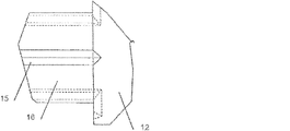
図1aおよび1bにはピン(10)が示されおり、これは、使用者が手動で物体(60)を第二区画(40)中に押し込むために使用するためのものであり、吸入器は、既にピン(10)が第一開口端部(21)において第一区画(30)中に部分的に挿入されている状態で使用者に供給されてもよい。 In FIGS. 1a and 1b a pin (10) is shown, which is for use by the user to manually push the object (60) into the second compartment (40), the inhaler is The pin (10) may already be supplied to the user with the pin (10) partially inserted into the first compartment (30) at the first open end (21).
図1bおよび3a〜cに示されているように、ピン(10)は、ヘッド(12)および長手方向に伸びる複数のリブ(16)を有しており、当該リブ(16)は、好ましくは、僅かに摩擦嵌合した状態で、第一区画(30)を形成するハウジング部分の内側表面(32)に接する。リブ(16)の間には空気流路(15)が形成され、これは、ピン(10)の長さ方向に沿って、空気がヘッド(12)から第一区画(30)中へ流入し、物体(60)がピンによって第二区画(40)中へと押し込まれた後には第二区画の空気流入ポート(50)へ流入するのを可能にする。ピンを第二区画(40)に向かって押し込む程度は使用者によって変わり、使用者は、第二区画において物質と混合されてマウスピースを通って吸入される外部空気の量を効果的に制御することができ、したがって当該ピンはバルブとしての役割を果たす。 As shown in FIGS. 1b and 3a-c, the pin (10) has a head (12) and a plurality of longitudinally extending ribs (16), the rib (16) being preferably In a slightly friction fitted state, it contacts the inner surface (32) of the housing part forming the first compartment (30). An air flow path (15) is formed between the ribs (16), which allows air to flow from the head (12) into the first compartment (30) along the length of the pin (10). After the object (60) is pushed into the second compartment (40) by the pin, it allows it to flow into the air inlet port (50) of the second compartment. The degree to which the pin is pushed toward the second compartment (40) varies from user to user, and the user effectively controls the amount of external air that is mixed with the substance and inhaled through the mouthpiece in the second compartment. Can thus act as a valve.
ピンが第二区画に向かって押し込まれる程度に応じた、バルブを通る気流のさらなる調節のために、空気流路(15)は、幅または深さが変化/増加するV字形状の溝を構成していてもよい。 For further adjustment of the airflow through the valve, depending on the degree to which the pin is pushed towards the second compartment, the air flow path (15) constitutes a V-shaped groove with varying / increasing width or depth You may do it.
ピン(10)は、好ましくは、非作動状態において配置した場合に、ピン(10)の近位の物体(60)の形状に一致する幾何学的形状(13)を、ヘッド(12)と反対側の端部に有しているか、あるいは、ピンの近位の物体より小さい半径の凹形の端部を有していてもよく、これにより、作動中に物質を取り込むための空間が密封体と放出装置(10)との間に形成されるということに留意されたい。 The pin (10) preferably has a geometrical shape (13) that matches the shape of the object (60) proximal to the pin (10) when placed in the non-actuated state, opposite the head (12). May have a concave end with a smaller radius than the object proximal to the pin, thereby providing a space for enclosing material during operation. Note that it is formed between the discharge device (10).
物体(60)は、好ましくは弾性であり、複数のチャンバー(62)が当該物体の間に作り出されるように配置される。当該物体は、その弾性により第一区画(30)の内部に拘束されるであろう。作動状態の場合、物体(60)は、僅かに広がるであろう。第一区画(30)は、原則として、物体が、第一区画と相補して、密封されたチャンバー(62)を形成し得るだけの長さの幾何学的形状を有し得、本態様では、円筒状の区画(30、40)と球上の物体(60)を想定しているが、円筒状の物体も使用することができる。 The object (60) is preferably elastic and is arranged such that a plurality of chambers (62) are created between the objects. The object will be restrained inside the first compartment (30) by its elasticity. In the activated state, the object (60) will spread slightly. The first compartment (30) may in principle have a geometric shape long enough to allow the object to form a sealed chamber (62) complementary to the first compartment, Although a cylindrical section (30, 40) and an object (60) on a sphere are assumed, a cylindrical object can also be used.
図1aおよび2aおよび2bは、吸入器ハウジングの円筒状の内壁が、好ましくは、第二区画(40)の長さ方向に沿って伸びる一連の細長い先鋭なリブ(42)を備えていることを示しており、第二区画(40)は、物体の周りの気流を最適化するために、したがって、吸入器内に収容されている物質と空気との混合を最適化するために、物体(60)より大きな断面を有し得る。物体の露出表面積を増加させるために、間隔を開けて配置された先鋭なリブが、吸入器に収容されかつ物体の表面へ付着している任意の液体物質の表面張力によって物体が付着し得る表面を効果的に提供する。 1a and 2a and 2b show that the cylindrical inner wall of the inhaler housing preferably comprises a series of elongated sharp ribs (42) extending along the length of the second compartment (40). The second compartment (40) is shown in order to optimize the airflow around the object, and thus to optimize the mixing of the substance and air contained in the inhaler. ) May have a larger cross-section. In order to increase the exposed surface area of an object, a surface where the sharp ribs spaced apart can be attached by the surface tension of any liquid substance contained in the inhaler and attached to the surface of the object Effectively provide.
図2aは、空気流入ポート(50)の領域に、吸入器の壁と一体的に成形された環状の柔軟な締め付け部(32)が存在し得ることを示している。当該締め付け部は、第二区画(40)内へ移動する物体(60)に対して僅かな抵抗を提供し得るだけでなく、吸入器(1)の作動状態において、第一区画(30)へ逆流する傾向のある第二区画(40)内の任意の液体に対する防壁も提供し得る。 FIG. 2a shows that in the region of the air inlet port (50) there can be an annular flexible clamping part (32) molded integrally with the wall of the inhaler. The clamping part can not only provide a slight resistance against the object (60) moving into the second compartment (40) but also to the first compartment (30) in the operating state of the inhaler (1). A barrier to any liquid in the second compartment (40) that tends to flow backwards may also be provided.
吸入部には、弾性体が吸入器から抜け出るのを防ぎ、物体(60)の1つが防壁に寄りかかっている場合でさえ空気が通過できるような構造を有する中央通気道を有する防壁(27)が備えられ得、当該中央通気道は、当該防壁を通る断面図に見られるように、星形構造を有し得る。 The inhalation part has a barrier (27) with a central airway that prevents the elastic body from coming out of the inhaler and allows air to pass even if one of the objects (60) leans against the barrier. The central airway may have a star structure as seen in a cross-sectional view through the barrier.
吸入器の第一端部(21)は、従来のニコチン保持容器、例えば、Nicotinellとして知られる製品など、と嵌合する寸法および比率に形成してもよい。 The first end (21) of the inhaler may be sized and proportioned to mate with a conventional nicotine holding container, such as a product known as Nicotinell.
図4は、多くの空気シリンダーが固定比率において垂直に取り付けられている固定フレーム(13')を示しており、(14')および(10')を参照されたい。 FIG. 4 shows a fixed frame (13 ′) with many air cylinders mounted vertically in a fixed ratio, see (14 ′) and (10 ′).
静電気を避けるために、弾性体(2'/60)は充填トレーから管(8')を通って挿入される。 In order to avoid static electricity, the elastic body (2 '/ 60) is inserted through the tube (8') from the filling tray.
フォトセル感度制御(9')を使用することにより、当該管は確実に完全に充填される。 The use of a photocell sensitivity control (9 ') ensures that the tube is completely filled.
固定された吸入器(1)が、周期的に前に送られる(13')の下の装置に配置される。弾性体の列が、空気シリンダー(14)によって前に押され、挿入位置に運ばれる。並んだ空気シリンダー(10')が作動するときはいつも、吸入器(1)の内側の所定の位置へとボールユニットが下向きに押される。 A fixed inhaler (1) is placed in the device under (13 ') that is periodically forwarded. The row of elastic bodies is pushed forward by the air cylinder (14) and brought to the insertion position. Whenever the side-by-side air cylinders (10 ') are actuated, the ball unit is pushed downward into place in the inhaler (1).
(14')が作動する際には、ボール(2')が時期尚早に落下してしまうのを防ぐために、滑動スリーブ(16')の位置がずらされることも留意されたい。 It should also be noted that when the (14 ') is activated, the sliding sleeve (16') is displaced in order to prevent the ball (2 ') from falling prematurely.
示された順序は100%自動化され、ボールユニット(2')は、セクションごとに、運ばれてきた1つまたは複数の吸入器の管に挿入される。 The sequence shown is 100% automated and the ball unit (2 ') is inserted into the inhaler tube or tubes that have been transported, section by section.
物体の挿入の際に空気が閉じ込められるのを避けるため、さらに(13')を、密封プロセスに必要な直径より小さいフィーダースリーブでボール(2')を押し込むように改良してもよい。ボールが放出される前に上記のスリーブが吸入器の管の中に入れられ、その後に、充填プロセスの一部として当該スリーブが引き戻される。これは、図4には示されていない。 To avoid trapping air during object insertion, (13 ′) may be further modified to push the ball (2 ′) with a feeder sleeve smaller than the diameter required for the sealing process. The sleeve is placed in the inhaler tube before the ball is released, after which the sleeve is withdrawn as part of the filling process. This is not shown in FIG.
上記の説明は、詳細:Y-Yにも示されている。 The above description is also shown in detail: YY.
Claims (29)
該第二区画(40)が少なくとも1つの空気流入ポート(50)を含み、該吸入器(1)が、該第一区画(30)の近位に第一端部(21)および該第二区画(40)の近位に第二端部(22)を有し、吸入部(27)が該第二端部(22)にあり、該第一区画(30)が、少なくとも1種の物質を貯蔵するためのものであり、かつ該吸入器(1)の非作動状態において、隣接して配置された複数の密封体(60)を含み、隣接する物体(60)の各対が、物質を収容するための密封されたチャンバー(62)を少なくとも部分的に規定し、該1種または複数種の物質が該第二区画(40)に収容されている吸入器(1)の作動状態が規定されるように該物体(60)が該少なくとも1種の物質と一緒に該第一区画(30)から該第二区画(40)中へと移動可能であり、それにより、該空気流入ポート(50)を通って流入しかつ該少なくとも1種の物質が該第二区画(40)に収容されている場合には該少なくとも1種の物質を例えば気化によって取り込んだ空気が、該吸入部(27)を介して吸入され得、該作動状態が該第一区画(30)内の放出装置を特徴とし、該放出装置が、該物体(60)を該第二区画中へと移動させるためのものであり、かつ作動状態において該空気流入ポート(50)へ該空気が流入することを可能にする、吸入器(1)。 An inhaler (1) comprising a housing having at least a first compartment (30) and a second compartment (40) and comprising one or more substances,
The second compartment (40) includes at least one air inlet port (50), and the inhaler (1) is disposed proximal to the first compartment (30) at a first end (21) and the second Proximal to the compartment (40) has a second end (22), the inhalation portion (27) is at the second end (22), and the first compartment (30) is at least one substance A plurality of sealing bodies (60) arranged adjacent to each other in a non-operating state of the inhaler (1), wherein each pair of adjacent objects (60) An operating state of the inhaler (1) that at least partially defines a sealed chamber (62) for containing the one or more substances, wherein the one or more substances are contained in the second compartment (40) As defined, the object (60) is movable with the at least one substance from the first compartment (30) into the second compartment (40), whereby the air inlet port When the at least one substance flows into the suction section (50) and the at least one substance is contained in the second compartment (40), the air that has taken in the at least one substance, for example, by vaporization, is (27) can be inhaled and the operating condition is characterized by a discharge device in the first compartment (30), the discharge device moving the object (60) into the second compartment And an inhaler (1) that allows the air to flow into the air inlet port (50) when in operation.
吸入器ハウジングのための固定具を有するフレームワークを提供する工程;
該吸入器ハウジングを該固定具に固定する工程;
第一弾性体(60)を第一区画(30)中へと押し込むことによって該弾性体を該第一区画中に位置決めする工程;
第一物質を、該第一弾性体に隣接する該第一区画中に投入する工程;
第二弾性体(60)を該第一物質に隣接して該第一区画中に位置決めし、その一方で、該第一および該第二弾性体によって形成される該区画に該物質が閉じ込められるように該第二弾性体を押し込む工程
を含む、前記請求項のいずれか一項記載の吸入器の製造方法。 Providing a plurality of objects, wherein the objects are elastic;
Providing a framework having a fixture for the inhaler housing;
Securing the inhaler housing to the fixture;
Positioning the elastic body in the first compartment by pushing the first elastic body (60) into the first compartment (30);
Introducing a first substance into the first compartment adjacent to the first elastic body;
A second elastic body (60) is positioned in the first compartment adjacent to the first material, while the material is confined to the compartment formed by the first and second elastic bodies. The method for manufacturing an inhaler according to any one of the preceding claims, comprising a step of pressing the second elastic body.
Applications Claiming Priority (5)
| Application Number | Priority Date | Filing Date | Title |
|---|---|---|---|
| DKPA201070084 | 2010-03-04 | ||
| DKPA201070084 | 2010-03-04 | ||
| DKPA201070227 | 2010-05-31 | ||
| DKPA201070227 | 2010-05-31 | ||
| PCT/DK2011/050067 WO2011107104A1 (en) | 2010-03-04 | 2011-03-04 | An inhalator |
Related Child Applications (1)
| Application Number | Title | Priority Date | Filing Date |
|---|---|---|---|
| JP2015255600A Division JP2016064301A (en) | 2010-03-04 | 2015-12-28 | Inhalator |
Publications (2)
| Publication Number | Publication Date |
|---|---|
| JP2013521023A true JP2013521023A (en) | 2013-06-10 |
| JP2013521023A5 JP2013521023A5 (en) | 2015-04-16 |
Family
ID=44541668
Family Applications (3)
| Application Number | Title | Priority Date | Filing Date |
|---|---|---|---|
| JP2012555296A Pending JP2013521023A (en) | 2010-03-04 | 2011-03-04 | Inhaler |
| JP2015255600A Pending JP2016064301A (en) | 2010-03-04 | 2015-12-28 | Inhalator |
| JP2017194764A Active JP6689243B2 (en) | 2010-03-04 | 2017-10-05 | Inhaler |
Family Applications After (2)
| Application Number | Title | Priority Date | Filing Date |
|---|---|---|---|
| JP2015255600A Pending JP2016064301A (en) | 2010-03-04 | 2015-12-28 | Inhalator |
| JP2017194764A Active JP6689243B2 (en) | 2010-03-04 | 2017-10-05 | Inhaler |
Country Status (14)
| Country | Link |
|---|---|
| US (1) | US10137261B2 (en) |
| EP (1) | EP2542285B8 (en) |
| JP (3) | JP2013521023A (en) |
| CN (1) | CN102917745B (en) |
| AU (1) | AU2011223344B2 (en) |
| BR (1) | BR112012022357B1 (en) |
| EA (1) | EA031660B1 (en) |
| ES (1) | ES2961294T3 (en) |
| IL (1) | IL221768A (en) |
| MX (1) | MX2012010170A (en) |
| MY (1) | MY165956A (en) |
| PL (1) | PL2542285T3 (en) |
| SG (1) | SG183554A1 (en) |
| WO (1) | WO2011107104A1 (en) |
Families Citing this family (14)
| Publication number | Priority date | Publication date | Assignee | Title |
|---|---|---|---|---|
| US20150238723A1 (en) * | 2012-08-20 | 2015-08-27 | Lk Investment A/S | Inhalator |
| US11793769B2 (en) | 2014-08-25 | 2023-10-24 | Jai Shankar Sukul | Device with compositions for delivery to the lungs, the oral mucosa and the brain |
| DE102014116742B3 (en) * | 2014-09-08 | 2015-07-16 | Smc System Management Consulting Gmbh | Method and device for producing an inhaler and inhaler |
| US10874139B2 (en) * | 2015-07-07 | 2020-12-29 | Altria Client Services Llc | E-vapor device including capsule containing pre-vapor formulation |
| GB201702206D0 (en) | 2017-02-10 | 2017-03-29 | British American Tobacco Investments Ltd | Vapour provision system |
| GB201721470D0 (en) | 2017-12-20 | 2018-01-31 | British American Tobacco Investments Ltd | Electronic aerosol provision system |
| GB201721477D0 (en) | 2017-12-20 | 2018-01-31 | British American Tobacco Investments Ltd | Electronic aerosol provision system |
| US20200245680A1 (en) * | 2018-03-29 | 2020-08-06 | Nwt Holdings Llc | Portable vaporizer |
| US11517685B2 (en) | 2019-01-18 | 2022-12-06 | Qnovia, Inc. | Electronic device for producing an aerosol for inhalation by a person |
| US11690963B2 (en) | 2018-08-22 | 2023-07-04 | Qnovia, Inc. | Electronic device for producing an aerosol for inhalation by a person |
| CN109171013A (en) * | 2018-09-28 | 2019-01-11 | 云南中烟工业有限责任公司 | A kind of liquid storage capsule and application thereof |
| CA3116862A1 (en) | 2018-10-18 | 2020-04-23 | Respira Technologies, Inc. | Electronic device for producing an aerosol for inhalation by a person |
| GB2586301B (en) | 2020-04-07 | 2021-08-25 | Splash Tm Gmbh | Stable-Foam inhalation Device and Cartridge |
| WO2023205385A1 (en) | 2022-04-22 | 2023-10-26 | Qnovia, Inc. | Electronic devices for aerosolizing and inhaling liquid |
Citations (1)
| Publication number | Priority date | Publication date | Assignee | Title |
|---|---|---|---|---|
| GB2002856A (en) * | 1977-08-20 | 1979-02-28 | Meinecke Ag | Turbine type flow meters |
Family Cites Families (19)
| Publication number | Priority date | Publication date | Assignee | Title |
|---|---|---|---|---|
| US4284089A (en) * | 1978-10-02 | 1981-08-18 | Ray Jon P | Simulated smoking device |
| IE65679B1 (en) * | 1984-09-14 | 1995-11-15 | Reynolds Tobacco Co R | Cigarette type smoking article |
| US5159940A (en) * | 1988-07-22 | 1992-11-03 | Philip Morris Incorporated | Smoking article |
| US5144962A (en) * | 1989-12-01 | 1992-09-08 | Philip Morris Incorporated | Flavor-delivery article |
| US5287850A (en) * | 1991-08-20 | 1994-02-22 | Habley Medical Technology Corporation | Timing and velocity controlled powered pharmaceutical inhaler |
| DE4338884C1 (en) * | 1993-11-13 | 1995-03-09 | Klaus Waretzi | Device for the inhalation of the active substance or aroma emitted by a carrier substance |
| PT101988B (en) * | 1997-04-04 | 2004-02-27 | Hovione Farmaciencia Sa | SYSTEM OF ORIENTATION AND POSITIONING OF AN OBJECT |
| JP3327826B2 (en) * | 1997-12-05 | 2002-09-24 | 日本たばこ産業株式会社 | Flavor producing articles and flavor producing instruments |
| DE19912461B4 (en) * | 1999-03-19 | 2006-07-20 | GSF - Forschungszentrum für Umwelt und Gesundheit GmbH | Device for limiting the flow at low differential pressures |
| US7415982B1 (en) | 2001-02-15 | 2008-08-26 | Sheridan Timothy B | Smokeless pipe |
| US7021561B2 (en) * | 2001-12-18 | 2006-04-04 | Becton, Dickinson And Company | Spray device and method |
| DK174521B1 (en) | 2002-02-26 | 2003-05-05 | Tage Wenzel Debess | Inhalator is used as alternative to known cigarette smoking and for breaking habit. It may also be used as dispensing unit for medical preparations |
| JP2005034021A (en) | 2003-07-17 | 2005-02-10 | Seiko Epson Corp | Electronic cigarette |
| DE202006001663U1 (en) * | 2006-02-03 | 2006-04-27 | Kieslich, Dirk | Smoke-free cigarette with nicotine and flavor cushions but without harmful combustion substances and side effects |
| EP1867357A1 (en) | 2006-06-13 | 2007-12-19 | TrendTech A/S | Inhaler |
| EP2002856A1 (en) * | 2007-06-15 | 2008-12-17 | TrendTech A/S | Multiple substance compartment duct container |
| US20090062745A1 (en) * | 2007-08-31 | 2009-03-05 | Can-Long Qiu | Safety Syringe |
| JP2009213618A (en) * | 2008-03-10 | 2009-09-24 | Canon Inc | Non-discharge liquid cartridge and liquid agent discharger |
| US20090297253A1 (en) * | 2008-06-02 | 2009-12-03 | Jaehee Yuu | Brush device for dispensing liquid material by using plunger means |
-
2011
- 2011-03-04 ES ES11750219T patent/ES2961294T3/en active Active
- 2011-03-04 JP JP2012555296A patent/JP2013521023A/en active Pending
- 2011-03-04 BR BR112012022357A patent/BR112012022357B1/en not_active IP Right Cessation
- 2011-03-04 US US13/582,032 patent/US10137261B2/en active Active
- 2011-03-04 MY MYPI2012003942A patent/MY165956A/en unknown
- 2011-03-04 PL PL11750219.5T patent/PL2542285T3/en unknown
- 2011-03-04 EA EA201290864A patent/EA031660B1/en not_active IP Right Cessation
- 2011-03-04 WO PCT/DK2011/050067 patent/WO2011107104A1/en active Application Filing
- 2011-03-04 SG SG2012064507A patent/SG183554A1/en unknown
- 2011-03-04 AU AU2011223344A patent/AU2011223344B2/en not_active Ceased
- 2011-03-04 CN CN201180017644.6A patent/CN102917745B/en active Active
- 2011-03-04 EP EP11750219.5A patent/EP2542285B8/en active Active
- 2011-03-04 MX MX2012010170A patent/MX2012010170A/en active IP Right Grant
-
2012
- 2012-09-04 IL IL221768A patent/IL221768A/en active IP Right Grant
-
2015
- 2015-12-28 JP JP2015255600A patent/JP2016064301A/en active Pending
-
2017
- 2017-10-05 JP JP2017194764A patent/JP6689243B2/en active Active
Patent Citations (1)
| Publication number | Priority date | Publication date | Assignee | Title |
|---|---|---|---|---|
| GB2002856A (en) * | 1977-08-20 | 1979-02-28 | Meinecke Ag | Turbine type flow meters |
Also Published As
| Publication number | Publication date |
|---|---|
| EA201290864A1 (en) | 2013-04-30 |
| ES2961294T3 (en) | 2024-03-11 |
| AU2011223344A1 (en) | 2012-10-25 |
| EP2542285B1 (en) | 2023-10-11 |
| IL221768A (en) | 2016-08-31 |
| JP2016064301A (en) | 2016-04-28 |
| MX2012010170A (en) | 2013-03-21 |
| EP2542285A4 (en) | 2015-07-22 |
| BR112012022357A2 (en) | 2016-07-05 |
| EP2542285A1 (en) | 2013-01-09 |
| US10137261B2 (en) | 2018-11-27 |
| CN102917745A (en) | 2013-02-06 |
| JP2018029609A (en) | 2018-03-01 |
| EA031660B1 (en) | 2019-02-28 |
| EP2542285C0 (en) | 2023-10-11 |
| PL2542285T3 (en) | 2024-03-25 |
| WO2011107104A1 (en) | 2011-09-09 |
| AU2011223344B2 (en) | 2016-04-21 |
| US20130056005A1 (en) | 2013-03-07 |
| EP2542285B8 (en) | 2023-11-15 |
| CN102917745B (en) | 2015-07-15 |
| BR112012022357B1 (en) | 2020-05-05 |
| MY165956A (en) | 2018-05-18 |
| SG183554A1 (en) | 2012-10-30 |
| JP6689243B2 (en) | 2020-04-28 |
Similar Documents
| Publication | Publication Date | Title |
|---|---|---|
| JP6689243B2 (en) | Inhaler | |
| RU2654999C2 (en) | Aerosol-generating system having piercing element | |
| RU2741417C2 (en) | Powder inhaler, providing two resistance to inhalation flow | |
| CN106455726B (en) | Aerosol-generating system with improved piercing member | |
| JP3570431B2 (en) | Weighing device | |
| CA1329098C (en) | Plastic mouthpiece for simulated smoking | |
| CN109922852A (en) | Inhalator with vortex end plug | |
| US20040055613A1 (en) | Volatile inhaler and method | |
| CN105792688A (en) | Aerosol-generating system for generating and controlling the quantity of nicotine salt particles | |
| CN109328083A (en) | Nicotine suction device system | |
| JPWO2004089126A1 (en) | Nicotine suction pipe and nicotine holder | |
| KR200461081Y1 (en) | Electronic cigarette cartridges with a system for preventing backflow | |
| CN108430551A (en) | Nicotine particles capsule | |
| CN109922851A (en) | The inhalator of chamber with size setting | |
| CN106455723A (en) | Aerosol generating system with a rupturing system for a container | |
| US20140190473A1 (en) | Inhalation pen | |
| CN107614039A (en) | Add taste element for suction apparatus | |
| US9375540B2 (en) | Nasal aroma breathing pipe | |
| GB2461008A (en) | Nicotine inhaler with flavour source | |
| CN109219462A (en) | Nicotine particle delivery consumptive material | |
| BR112019023202A2 (en) | inhaler article with occluded airflow element | |
| KR20230043142A (en) | inhaler items | |
| KR101756725B1 (en) | Contact type Multi cartridge type electronic cigarette apparatus | |
| EP2002856A1 (en) | Multiple substance compartment duct container | |
| WO2023052112A1 (en) | Vapour delivery apparatus |
Legal Events
| Date | Code | Title | Description |
|---|---|---|---|
| A621 | Written request for application examination |
Free format text: JAPANESE INTERMEDIATE CODE: A621 Effective date: 20140228 |
|
| A131 | Notification of reasons for refusal |
Free format text: JAPANESE INTERMEDIATE CODE: A131 Effective date: 20141112 |
|
| A977 | Report on retrieval |
Free format text: JAPANESE INTERMEDIATE CODE: A971007 Effective date: 20141114 |
|
| A601 | Written request for extension of time |
Free format text: JAPANESE INTERMEDIATE CODE: A601 Effective date: 20150130 |
|
| A521 | Request for written amendment filed |
Free format text: JAPANESE INTERMEDIATE CODE: A523 Effective date: 20150225 |
|
| A524 | Written submission of copy of amendment under article 19 pct |
Free format text: JAPANESE INTERMEDIATE CODE: A524 Effective date: 20150225 |
|
| RD04 | Notification of resignation of power of attorney |
Free format text: JAPANESE INTERMEDIATE CODE: A7424 Effective date: 20150618 |
|
| A02 | Decision of refusal |
Free format text: JAPANESE INTERMEDIATE CODE: A02 Effective date: 20150831 |