JP2013520873A - Communication device with multi-function control - Google Patents
Communication device with multi-function control Download PDFInfo
- Publication number
- JP2013520873A JP2013520873A JP2012553925A JP2012553925A JP2013520873A JP 2013520873 A JP2013520873 A JP 2013520873A JP 2012553925 A JP2012553925 A JP 2012553925A JP 2012553925 A JP2012553925 A JP 2012553925A JP 2013520873 A JP2013520873 A JP 2013520873A
- Authority
- JP
- Japan
- Prior art keywords
- function
- time period
- response
- elongate roller
- communication device
- Prior art date
- Legal status (The legal status is an assumption and is not a legal conclusion. Google has not performed a legal analysis and makes no representation as to the accuracy of the status listed.)
- Pending
Links
Images


Classifications
-
- G—PHYSICS
- G06—COMPUTING; CALCULATING OR COUNTING
- G06F—ELECTRIC DIGITAL DATA PROCESSING
- G06F3/00—Input arrangements for transferring data to be processed into a form capable of being handled by the computer; Output arrangements for transferring data from processing unit to output unit, e.g. interface arrangements
- G06F3/01—Input arrangements or combined input and output arrangements for interaction between user and computer
- G06F3/03—Arrangements for converting the position or the displacement of a member into a coded form
- G06F3/033—Pointing devices displaced or positioned by the user, e.g. mice, trackballs, pens or joysticks; Accessories therefor
- G06F3/0338—Pointing devices displaced or positioned by the user, e.g. mice, trackballs, pens or joysticks; Accessories therefor with detection of limited linear or angular displacement of an operating part of the device from a neutral position, e.g. isotonic or isometric joysticks
-
- H—ELECTRICITY
- H04—ELECTRIC COMMUNICATION TECHNIQUE
- H04M—TELEPHONIC COMMUNICATION
- H04M1/00—Substation equipment, e.g. for use by subscribers
- H04M1/72—Mobile telephones; Cordless telephones, i.e. devices for establishing wireless links to base stations without route selection
- H04M1/724—User interfaces specially adapted for cordless or mobile telephones
- H04M1/72466—User interfaces specially adapted for cordless or mobile telephones with selection means, e.g. keys, having functions defined by the mode or the status of the device
-
- H—ELECTRICITY
- H04—ELECTRIC COMMUNICATION TECHNIQUE
- H04W—WIRELESS COMMUNICATION NETWORKS
- H04W4/00—Services specially adapted for wireless communication networks; Facilities therefor
- H04W4/06—Selective distribution of broadcast services, e.g. multimedia broadcast multicast service [MBMS]; Services to user groups; One-way selective calling services
- H04W4/10—Push-to-Talk [PTT] or Push-On-Call services
-
- G—PHYSICS
- G06—COMPUTING; CALCULATING OR COUNTING
- G06F—ELECTRIC DIGITAL DATA PROCESSING
- G06F3/00—Input arrangements for transferring data to be processed into a form capable of being handled by the computer; Output arrangements for transferring data from processing unit to output unit, e.g. interface arrangements
- G06F3/01—Input arrangements or combined input and output arrangements for interaction between user and computer
- G06F3/03—Arrangements for converting the position or the displacement of a member into a coded form
- G06F3/033—Pointing devices displaced or positioned by the user, e.g. mice, trackballs, pens or joysticks; Accessories therefor
- G06F3/0362—Pointing devices displaced or positioned by the user, e.g. mice, trackballs, pens or joysticks; Accessories therefor with detection of 1D translations or rotations of an operating part of the device, e.g. scroll wheels, sliders, knobs, rollers or belts
-
- H—ELECTRICITY
- H04—ELECTRIC COMMUNICATION TECHNIQUE
- H04M—TELEPHONIC COMMUNICATION
- H04M1/00—Substation equipment, e.g. for use by subscribers
- H04M1/02—Constructional features of telephone sets
- H04M1/23—Construction or mounting of dials or of equivalent devices; Means for facilitating the use thereof
- H04M1/233—Construction or mounting of dials or of equivalent devices; Means for facilitating the use thereof including a pointing device, e.g. roller key, track ball, rocker switch or joystick
-
- H—ELECTRICITY
- H04—ELECTRIC COMMUNICATION TECHNIQUE
- H04M—TELEPHONIC COMMUNICATION
- H04M1/00—Substation equipment, e.g. for use by subscribers
- H04M1/02—Constructional features of telephone sets
- H04M1/23—Construction or mounting of dials or of equivalent devices; Means for facilitating the use thereof
- H04M1/236—Construction or mounting of dials or of equivalent devices; Means for facilitating the use thereof including keys on side or rear faces
-
- H—ELECTRICITY
- H04—ELECTRIC COMMUNICATION TECHNIQUE
- H04W—WIRELESS COMMUNICATION NETWORKS
- H04W88/00—Devices specially adapted for wireless communication networks, e.g. terminals, base stations or access point devices
- H04W88/02—Terminal devices
-
- H—ELECTRICITY
- H01—ELECTRIC ELEMENTS
- H01H—ELECTRIC SWITCHES; RELAYS; SELECTORS; EMERGENCY PROTECTIVE DEVICES
- H01H19/00—Switches operated by an operating part which is rotatable about a longitudinal axis thereof and which is acted upon directly by a solid body external to the switch, e.g. by a hand
- H01H19/001—Thumb wheel switches
- H01H19/003—Thumb wheel switches having a pushbutton actuator
Abstract
無線トランシーバ(206,208)の機能を制御するシステム(100)及び方法(400)を提供する。少なくとも1つの機能は、制御素子(102,300)の長桿状ローラの中心の押下、第1の時間期間の長桿状ローラ(302)の第1の周辺端部(FPEP)の押下、第2の時間期間の長桿状ローラの第2の周辺端部(SPEP)の押下、長桿状ローラの中心軸の周りの長桿状ローラの回転、第1の時間期間よりも長い第3の時間期間のFPEP(352)の押下、及び/又は第2の時間期間よりも長い第4の時間期間のSPEP(354)の押下に応答して、制御される。A system (100) and method (400) for controlling the functionality of a wireless transceiver (206, 208) are provided. At least one function is to depress the center of the elongate roller of the control element (102, 300), depress the first peripheral edge (FPEP) of the elongate roller (302) for the first time period, the second Depressing the second peripheral end (SPEP) of the elongate roller for a time period, rotation of the elongate roller around the central axis of the elongate roller, FPEP for a third time period longer than the first time period ( 352) and / or in response to pressing the SPEP (354) for a fourth time period longer than the second time period.
Description
本発明の配置は、通信システム、より具体的には、多機能長桿状ローラを用いて無線トランシーバを制御するシステム及び方法に関する。 The arrangement of the present invention relates to a communication system, and more particularly to a system and method for controlling a wireless transceiver using a multifunctional elongate roller.
当該技術では、様々な通信ネットワークが知られている。そのような通信ネットワークには、地上モバイルラジオ(Land Mobile Radio)(LMR)ネットワーク、ワイドバンド符号分割多重アクセス(Wideband Code Division Multiple Access)(WCDMA)に基づくネットワーク、符号分割多重アクセス(Code Division Multiple Access)(CDMA)に基づくネットワーク、無線ローカルエリアネットワーク(Wireless Local Area Network)(WLAN)、エンハンスドデータレート・フォー・GSMエボリューション(Enhanced Data rates for GSM Evolution)(EDGE)に基づくネットワーク、及びロングタームエボリューション(Long Term Evolution)(LTE)に基づくネットワークがある。それらの通信ネットワークの夫々は、複数の通信装置と、通信装置間の通信を助けるネットワーク設備とを有する。夫々の通信ネットワークは、しばしば、サービスユーザにグループ呼出サービスを提供する。グループ呼出サービスは、サービスユーザ(例えば、第1応答者)が特定のトークグループ又はソーシャルメディアプロファイルに関連する他のサービスユーザ(例えば、他の第1応答者)と同時に話すことができるサービスである。グループ呼出サービスは、プッシュ・ツー・トーク(Push-To-Talk)(PTT)グループ呼出サービスによって実施され得る。PTTグループ呼出サービスは、PTTサービスユーザが、通信装置のPTTボタンを押すことによって、特定のトークグループ又はソーシャルメディアプロファイルの他のPTTサービスユーザと直ぐに話すことができる即時サービスである。 Various communication networks are known in the art. Such communication networks include Land Mobile Radio (LMR) networks, networks based on Wideband Code Division Multiple Access (WCDMA), Code Division Multiple Access (Code Division Multiple Access). ) (CDMA) based networks, Wireless Local Area Networks (WLAN), Enhanced Data rates for GSM Evolution (EDGE) based networks, and Long Term Evolution ( There are networks based on Long Term Evolution) (LTE). Each of these communication networks includes a plurality of communication devices and network equipment that assists communication between the communication devices. Each communication network often provides group call services to service users. A group call service is a service that allows a service user (eg, a first responder) to speak simultaneously with other service users (eg, other first responders) associated with a particular talk group or social media profile. . The group call service may be implemented by a push-to-talk (PTT) group call service. The PTT group call service is an immediate service that allows a PTT service user to immediately talk to other PTT service users in a particular talk group or social media profile by pressing the PTT button on the communication device.
幾つかの場合において、通信装置は地上モバイルラジオを有する。通常、ラジオの夫々は、複数の回転ノブと、それらの無線トランシーバを制御するPTTボタンとを有する。回転ノブは、ラジオの上部パネルに配置される。第1の回転ノブは、PTT呼出が行われるべき個人又はトークグループを選択するために設けられる。第2の回転ノブは、ラジオのオーディオボリュームを制御するために設けられる。PTTボタンは、ラジオの側面パネルに配置される。結果として、ラジオのユーザは、ラジオのラジオ受信機を制御するために一本の指だけを用いることはできない。また、両手が、好ましくなく、ラジオを保持して、複数の回転ノブによりラジオの機能設定を変更するためには必要とされる。 In some cases, the communication device has a terrestrial mobile radio. Each radio typically has a plurality of rotary knobs and a PTT button that controls their radio transceiver. The rotary knob is located on the top panel of the radio. A first rotary knob is provided to select an individual or talk group where a PTT call should be made. The second rotary knob is provided to control the audio volume of the radio. The PTT button is located on the side panel of the radio. As a result, radio users cannot use only one finger to control the radio receiver of the radio. Also, both hands are undesirable and are required to hold the radio and change the radio function settings with multiple rotary knobs.
本発明の実施形態は、無線トランシーバを制御する方法に関する。方法は、概して、制御素子の長桿状ローラの中心の押下に応答して、無線トランシーバの第1の機能を制御するステップを有する。無線トランシーバの第2の機能は、第1の時間期間(例えば、2秒より短い)の長桿状ローラの第1の周辺端部の押下に応答して、制御される。無線トランシーバの第3の機能は、第2の時間期間(例えば、2秒より短い)の長桿状ローラの第2の周辺端部の押下に応答して、制御される。第2の周辺端部は、第1の周辺端部と対向する。無線トランシーバの第4の機能は、長桿状ローラの中心軸の周りの長桿状ローラの回転に応答して、制御される。無線トランシーバの第5の機能は、第1の時間期間よりも長い第3の時間期間(例えば、2秒より長い)の第1の周辺端部の押下に応答して、制御される。無線トランシーバの第6の機能は、第2の時間期間よりも長い第4の時間期間(例えば、2秒より長い)の第2の周辺端部の押下に応答して、制御される。第1、第2、第3、第4、第5及び第6の機能の夫々は、オーディオボリューム機能、チャネル選択機能、ミュート機能、輝度選択機能、オン・オフ機能、再生機能、巻き戻し機能、早送り機能、一時停止機能、チャネル呼び戻し機能、カメラ機能、トークグループ選択機能、メディアプロファイル選択機能、個別呼出機能、グループ呼出機能、緊急呼出機能、地図選択機能、優先事項選択機能、ユーザインターフェース選択機能及び/又はPTT機能を有することができるが、これらに限られない。 Embodiments of the invention relate to a method for controlling a wireless transceiver. The method generally includes controlling a first function of the wireless transceiver in response to pressing the center of the elongated roller of the control element. The second function of the wireless transceiver is controlled in response to pressing of the first peripheral edge of the elongate roller for a first time period (eg, less than 2 seconds). A third function of the wireless transceiver is controlled in response to pressing of the second peripheral edge of the elongate roller for a second time period (eg, less than 2 seconds). The second peripheral end portion faces the first peripheral end portion. The fourth function of the wireless transceiver is controlled in response to the rotation of the elongate roller about the central axis of the elongate roller. The fifth function of the wireless transceiver is controlled in response to pressing of the first peripheral edge for a third time period (eg, greater than 2 seconds) that is longer than the first time period. The sixth function of the wireless transceiver is controlled in response to pressing of the second peripheral edge for a fourth time period (eg, greater than 2 seconds) that is longer than the second time period. Each of the first, second, third, fourth, fifth and sixth functions includes an audio volume function, a channel selection function, a mute function, a brightness selection function, an on / off function, a playback function, a rewind function, Fast forward function, pause function, channel recall function, camera function, talk group selection function, media profile selection function, individual call function, group call function, emergency call function, map selection function, priority selection function, user interface selection function and Although it can have a PTT function, it is not restricted to these.
また、本発明の実施形態は、デバイスを制御する装置及びシステムに関する。デバイスは、ラジオ、モバイル電話、セルラー電話、パーソナルデジタルアシスタント、グローバルポジショニングデバイス、パーソナルコンピュータ、テレビジョン、車間通信デバイス、及びこれらの装置と協働するアクセサリを有することができるが、これらに限られない。特に、装置及びシステムは、上記の方法を実施する。そのようなものとして、装置及びシステムは、制御素子及び少なくとも1つのコントローラを有する。制御素子は長桿状ローラを有する。コントローラは、長桿状ローラの中心の押下に応答してデバイスの第1の機能を制御するよう構成される。コントローラは、また、第1の時間期間の長桿状ローラの第1の周辺端部の押下に応答してデバイスの第2の機能を制御するよう構成される。コントローラは、更に、第2の時間期間の長桿状ローラの第2の周辺端部の押下に応答してデバイスの第3の機能を制御するよう構成される。デバイスの第4の機能は、長桿状ローラの中心軸の周りの長桿状ローラの回転に応答してコントローラによって制御される。デバイスの第5の機能は、第1の時間期間よりも長い第3の時間期間の第1の周辺端部の押下に応答してコントローラによって制御される。デバイスの第6の機能は、第2の時間期間よりも長い第3の時間期間の第2の周辺端部の押下に応答してコントローラによって制御される。 Embodiments of the present invention also relate to an apparatus and system for controlling a device. Devices can include, but are not limited to, radios, mobile phones, cellular phones, personal digital assistants, global positioning devices, personal computers, televisions, inter-vehicle communication devices, and accessories that work with these devices. . In particular, the apparatus and system implement the above method. As such, the apparatus and system have a control element and at least one controller. The control element has an elongate roller. The controller is configured to control the first function of the device in response to pressing of the center of the elongate roller. The controller is also configured to control the second function of the device in response to depression of the first peripheral edge of the elongate roller during the first time period. The controller is further configured to control a third function of the device in response to pressing of the second peripheral edge of the elongate roller for a second time period. The fourth function of the device is controlled by the controller in response to rotation of the elongate roller about the central axis of the elongate roller. The fifth function of the device is controlled by the controller in response to pressing of the first peripheral edge for a third time period longer than the first time period. The sixth function of the device is controlled by the controller in response to pressing of the second peripheral edge for a third time period that is longer than the second time period.
実施形態は、以下の図面を参照して記載される。図面において、同じ参照符号は同じ事項を表す。 Embodiments are described with reference to the following drawings. In the drawings, the same reference numerals represent the same items.
本発明について、図面を参照して記載する。図は実寸通りではなく、それらは単に本発明を説明するために与えられている。本発明の幾つかの態様について、以下、説明のための実例応用を参照して記載する。多数の具体的な詳細、関係及び方法は本発明の十分な理解を提供するために示されていることが理解されるべきである。なお、当業者には容易に理解されるように、本発明は、それらの具体的な詳細の1又はそれ以上を用いずとも、あるいは他の方法を用いても、実施され得る。他の例では、従来の構成及び動作は、本発明を不明りょうにすることを避けるために詳細に示されない。本発明は、一部が他の動作又は事象とともに異なる順序で及び/又は同時に起こりうるように、示されている動作又は事象の順序によって制限されない。更に、示されている全ての動作又は事象が、本発明に従う方法を実施するのに必要とされるわけではない。 The present invention will be described with reference to the drawings. The figures are not to scale, they are provided merely to illustrate the present invention. Several aspects of the invention are described below with reference to illustrative applications for illustration. It should be understood that numerous specific details, relationships and methods are set forth in order to provide a thorough understanding of the present invention. It will be appreciated by persons skilled in the art that the present invention may be practiced without one or more of these specific details, or with other methods. In other instances, conventional structures and operations are not shown in detail in order to avoid obscuring the present invention. The invention is not limited by the order of operations or events shown, as some may occur in different orders and / or simultaneously with other operations or events. Moreover, not all illustrated acts or events are required to implement a methodology in accordance with the present invention.
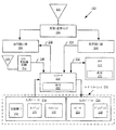
ここで図1を参照すると、本発明の1又はそれ以上の方法実施形態を実施する例となる通信デバイス100のブロックが与えられている。通信デバイス100は、携帯型地上モバイルラジオであるよう図1では示されているが、本発明の実施形態はこの点に制限されない。例えば、通信デバイス100は、代替的に、モバイル電話、セルラー電話、パーソナルデジタルアシスタント、グローバルポジショニングデバイス、パーソナルコンピュータ、テレビジョン、車間通信デバイス、又は他の通信デバイスを有することができるが、これらに限られない。それらの場合の夫々において、通信デバイス100は、概して、筐体104、アンテナ106及び内部回路(図1では図示せず。)を有する。通信デバイス100は、制御素子(例えば、PTTボタン又はスイッチ)102及び他のユーザインターフェース部品108を更に有する。
Referring now to FIG. 1, a block of an
幾つかの実施形態において、図1に示される通信デバイス100は、概して、サービスユーザへのデータ通信サービス、個別呼出サービス又はグループ呼出サービスの提供を助けるよう構成される。データ通信サービスは、一般的に、サービスユーザがデータメッセージを送信及び/又は受信することができるサービスである。個別呼出サービスは、一般的に、サービスユーザが1人の他のサービスユーザと話すことができるサービスである。グループ呼出サービスは、サービスユーザが特定のトークグループ又はソーシャルメディアプロファイルに関連する1又はそれ以上のサービスユーザと話すことができるサービスである。グループ呼出サービスは、PTTグループ呼出サービスによって実施され得る。PTTグループ呼出サービスは、PTTサービスユーザが、通信デバイス100の制御素子102を作動させることによって、特定のトークグループ又はソーシャルメディアプロファイルの他のPTTサービスユーザと直ぐに話すことができる即時サービスである。
In some embodiments, the
特に、通信デバイス100は、地上モバイルラジオ(Land Mobile Radio)(LMR)に基づく通信システム、グローバルポジショニングシステム(Global Positioning System)(GPS)、セルラーに基づく通信システム、又は他の無線通信システムにおいて動作するよう構成される。セルラーに基づくシステムは、第2世代(2G)互換システム及び/又は第3世代(3G)互換システム及び/又は第4世代(4G)互換システムを有することができるが、これらに限られない。ここで使用される語句「第2世代(2G)」は、第2世代の無線電話技術に言及する。ここで使用される語句「第3世代(3G)」は、第3世代の無線電話技術に言及する。ここで使用される語句「第4世代(4G)」は、第4世代の無線電話技術に言及する。この場合において、通信デバイス100は、様々な2Gデータサービス(例えば、テキストメッセージ)、3Gデータサービス(例えば、映像呼出)、及び/又は4Gデータサービス(例えば、ウルトラワイドバンドインターネットアクセス)をサポートすることができる。本発明の実施形態はこの点に制限されない。
In particular, the
通信デバイス100は、単一の通信プロトコル又は複数の通信プロトコルを用いることができる。例えば、通信デバイス100がLMRラジオである場合には、通信デバイス100は次の通信プロトコル、すなわち、テレストリアル・トランクド・ラジオ(Terrestrial Trunked Radio)(TETRA)トランスポートプロトコル、P25トランスポートプロトコル、オープンスカイ(OPENSKY)プロトコル、及びエンハンスドデジタルアクセス通信システム(Enhanced Digital Access Communication System)(EDACS)プロトコル、のうち1又はそれ以上を用いることができる。通信デバイス100がセルラー電話である場合には、通信デバイス100は、次の通信プロトコル、すなわち、ワイドバンド符号分割多重アクセス(WCDMA)に基づくプロトコル、符号分割多重アクセス(CDMA)に基づくプロトコル、無線ローカルエリアネットワーク(WLAN)に基づくプロトコル、エンハンスドデータレート・フォー・GSMエボリューション(EDGE)ネットワークに基づくプロトコル、及びロングタームエボリューション(LTE)ネットワークに基づくプロトコル、のうち1又はそれ以上を用いることができる。本発明の実施形態はこの点に制限されない。
The
通信デバイス100のより詳細なブロック図が図2において与えられている。特に、通信デバイス100は、図2で示されるものよりも多い又は少ない構成要素を有してよい。しかし、示される構成要素は、本発明を実施する実施例を開示するのに十分である。図2のハードウェア・アーキテクチャは、そのユーザへのグループ呼出サービスの提供を助けるよう構成される典型的な通信デバイスの一実施形態を表す。
A more detailed block diagram of
図2に示されるように、通信デバイス100は、無線周波数(RF)信号を受信及び送信するためのアンテナ106を有する。受信/送信(Rx/Tx)スイッチ204は、当業者になじみの方法において、アンテナ106を送信器回路206及び受信器回路208へ選択的に結合する。受信器回路208は、ネットワーク(図2において図示せず。)から受信されたRF信号を復調及びデコードして、その信号から情報を得る。受信器回路208は、電気接続234を介してコントローラ210へ結合される。受信器回路208は、デコードされたRF信号情報をコントローラ210へ供給する。コントローラ210は、通信デバイス100の機能に従って、デコードされたRF信号情報を用いる。
As shown in FIG. 2, the
また、コントローラ210は、情報をRF信号にエンコード及び変調するために送信器回路206へ情報を供給する。然るに、コントローラ210は、電気接続238を介して送信器回路206へ結合される。送信器回路208は、外部デバイス(例えば、図2に図示されていないネットワーク設備)への送信のために、RF信号をアンテナ106へ送る。
アンテナ240は、グローバルポジショニングシステム(GPS)信号を受信するためにGPS受信器回路214へ結合される。GPS受信器回路214は、GPS信号を復調及びデコードして、その信号からGPS位置情報を取り出す。GPS位置情報は、通信デバイス100の位置を示す。GPS受信器回路214は、デコードされたGPS位置情報をコントローラ210へ供給する。そのようなものとして、GPS受信器回路214は、電気接続236を介してコントローラ210へ結合される。コントローラ210は、通信デバイス100の機能に従って、デコードされたGPS位置情報を用いる。
The
コントローラ210は、デコードされたRF信号情報及びデコードされたGPS位置情報を通信デバイス100のメモリ212に格納する。然るに、メモリ212は、電気接続232を介してコントローラ210へ結合され且つコントローラ210によってアクセス可能である。メモリ212は、揮発性メモリ及び/又は不揮発性メモリであってよい。例えば、メモリ212は、ランダムアクセスメモリ(RAM)、動的ランダムアクセスメモリ(DRAM)、静的ランダムアクセスメモリ(SRAM)、読出専用メモリ(ROM)及びフラッシュメモリを有することができるが、これらに限られない。
The
図2に示されるように、命令250の1又はそれ以上の組がメモリ212に記憶されている。また、命令250は、通信デバイス100によるそれらの実行の間、完全に又は少なくとも部分的に、コントローラ210内にあってよい。これに関連して、メモリ212及びコントローラ210は、機械により読出可能な媒体を構成することができる。ここで使用される語「機械により読出可能な媒体」は、命令250の1又はそれ以上の組を記憶する単一の媒体又は複数の媒体に言及する。また、ここで使用される語「機械により読出可能な媒体」は、通信デバイス100による実行のために命令250の組を記憶し、エンコードし、又は坦持し、且つ、通信デバイス100に本開示の方法の1又はそれ以上を実行させるあらゆる媒体に言及する。
As shown in FIG. 2, one or more sets of
コントローラ210は、更に、ユーザインターフェース230へ接続される。ユーザインターフェース230は、ユーザが通信デバイス100にインストールされたソフトウェアアプリケーション(図2には図示せず。)と相互作用してそれを制御することを可能にするよう構成された入力デバイス216、出力デバイス224及びソフトウェアルーチン(図2には図示せず。)を有する。入力デバイス216及び出力デバイス224は、夫々、ディスプレイ228、スピーカ226、キーパッド220、指示パッド(図2には図示せず。)、指示ノブ(図2には図示せず。)、マイクロフォン222及び制御素子(例えば、PTTボタン又はスイッチ)102を有するが、これらに限られない。ディスプレイ228は、タッチスクリーン入力に対応するよう設計されてよい。
The
ユーザインターフェース230は、通信デバイス100にインストールされたグループ呼出アプリケーション(図2には図示せず。)、PTT呼出アプリケーション(図2には図示せず。)、ソーシャルメディアアプリケーション、インターネットアプリケーション及び他のタイプのアプリケーション(図2には図示せず。)を起動するためのユーザーソフトウェア間の相互作用を助けるよう動作する。グループ呼出アプリケーション及びPTT呼出アプリケーション(図2には図示せず。)は、通信デバイス100のユーザへグループ呼出サービスを提供するよう動作する。
The user interface 230 may be a group call application (not shown in FIG. 2), a PTT call application (not shown in FIG. 2), a social media application, an Internet application, and other types installed on the
本発明の一実施形態に従って、制御素子102は、PTTスイッチとして機能するよう構成される。そのようなものとして、制御素子102は、呼出アプリケーションを起動する単一のスイッチ又はボタンをユーザに提供する。例えば、呼出アプリケーションは、制御素子102の中心の押下に応答して起動され得る。呼出アプリケーションは、通信デバイス100のユーザへの呼出サービスの提供を助ける。そのようなものとして、呼出アプリケーションは、通信動作を実行するよう動作する。通信動作は、メッセージ生成動作、メッセージ通信動作、ボイスパケット記録動作、ボイスパケット待ち動作及びボイスパケット通信動作を有することができるが、これらに限られない。
In accordance with one embodiment of the present invention, the
制御素子102は、PTT機能以外の様々な動作を制御するための多機能デバイスとして有利に構成される。そのようなものとして、制御素子102は、それらの様々な他の動作を制御するために使用され得る様々なスイッチ位置を有する。例えば、制御素子102は、通信デバイス100の特定の機能を選択及び/又は制御するための二次スイッチ又はボタン手段をユーザに提供する。より具体的には、通信デバイス100の機能は、所定時間期間(例えば、2秒よりも短い又は長い)の制御素子102の周辺端部の押下に応答して、制御素子102によって制御される。機能は、オーディオボリューム機能、チャネル選択機能、ミュート機能、輝度選択機能、オン・オフ機能、再生機能、巻き戻し機能、早送り機能、一時停止機能、チャネル呼び戻し機能、カメラ機能、トークグループ選択機能、メディアプロファイル選択機能、緊急呼出機能、地図選択機能、優先事項選択機能、及びユーザインターフェース選択機能を有することができるが、これらに限られない。本発明の実施形態はこの点に制限されない。
The
制御素子102は、通信デバイス100の特定の機能を選択及び/又は制御するための回転手段を更に備える。例えば、通信デバイス100の特定の機能は、制御素子102の中心軸の周りの制御素子102の回転に応答して、制御素子102によって制御される。機能は、オーディオボリューム機能、チャネル選択機能、ミュート機能、輝度選択機能、オン・オフ機能、再生機能、巻き戻し機能、早送り機能、一時停止機能、チャネル呼び戻し機能、カメラ機能、トークグループ選択機能、緊急呼出機能、地図選択機能、優先事項選択機能、ユーザインターフェース選択機能及びメディアプロファイル選択機能を有することができるが、これらに限られない。本発明の実施形態はこの点に制限されない。ここで、制御素子102の実施例について、図3に関連して記載する。
The
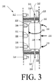
図3を参照すると、本発明を理解するために有用な、制御素子102の実施例の概略図が与えられている。制御素子102を実施する多数の方法があることが理解されるべきである。そのようなものとして、本発明は、図3に示される具体的な配置に制限されない。
Referring to FIG. 3, a schematic diagram of an embodiment of
図3に示されるように、制御素子102は、長桿状ローラ302、シャフト304、スイッチ306、308、310、光学式ポジション検出器312、314、及び弾性部材316、318、320、322を有する。長桿状ローラ302は、少なくとも部分的に通信デバイス100の筐体104から外に突き出るように筐体104において配置される。このように、長桿状ローラ302は、通信デバイス100のユーザに容易にアクセス可能である。なお、本発明の実施形態はこの点に制限されない。例えば、長桿状ローラ302は、代替的に、筐体104の表面に埋め込まれ、又は筐体104の表面と同一平面であってよい。
As shown in FIG. 3, the
本発明の一態様に従って、長桿状ローラ302は、概して、円筒形状を有する。そのようなものとして、長桿状ローラ302は、有利に、その中心軸360の長さに沿っていくらか引き伸ばしたように配置される。幾つかの実施形態では、長桿状ローラ302は、従来の円筒形状からいくらか外れた形状を有してよい。よって、例えば、長桿状ローラ302は、凸状又は凹状の側面を有してよい。また、長桿状ローラ302の表面は滑らかであっても又はそうでなくてもよい。
In accordance with one aspect of the present invention, the
長桿状ローラ302は、図3に示される安静位から図4〜7に示されるような複数の作動位置へ移るよう構成される。作動位置の夫々において、通信デバイス100の特定の機能は選択又は制御される。一実施形態に従って、シャフト304又は長桿状ローラ302は、通信デバイス100の筐体104において形成される導管(図3には図示せず。)内を導かれる。
The
長桿状ローラ302は、通信デバイス100の特定の機能を制御するために、図3に示される安静位から図4に示される第1の作動位置へ移行され得る。図4に示されるように、位置移行は、短時間(例えば、2秒より短い)又は長時間(例えば、2秒より長い)長桿状ローラ302の露出面326の下部周辺端部354を押し下げることによって、達成され得る。第1の作動位置において、スイッチ310のアクチュエータ328は、図4に示されるように、長桿状ローラ302によって押される。アクチュエータ328の押下の結果として、スイッチ310は、長桿状ローラ302が第1の作動位置にあることを示すように、閉又は開位置に置かれる。幾つかの実施形態において、通信デバイス100は、(a)長桿状ローラ302が押し下げられる時間量を追跡し、(b)ボタン押下の持続時間に基づき通信デバイス100の動作パラメータを変更するよう、動作を実行する。
The
同様に、長桿状ローラ302は、通信デバイス100の特定の機能を制御するために、図3に示される安静位から図5に示される第2の作動位置へ移るよう構成される。図5に示されるように、位置移行は、短時間(例えば、2秒より短い)又は長時間(例えば、2秒より長い)長桿状ローラ302の露出面326の上部周辺端部352を押し下げることによって、達成され得る。第2の作動位置において、スイッチ306のアクチュエータ330は、図5に示されるように、長桿状ローラ302によって押される。アクチュエータ330の押下の結果として、スイッチ306は、長桿状ローラ302が第2の作動位置にあることを示すように、閉又は開位置に置かれる。幾つかの実施形態において、通信デバイス100は、(a)長桿状ローラ302が押し下げられる時間量を追跡し、(b)ボタン押下の持続時間に基づき通信デバイス100の動作パラメータを変更するよう、動作を実行する。
Similarly, the
また、長桿状ローラ302は、通信デバイス100の特定の機能を制御するために、図3に示される安静位から図6に示される第3の作動位置へ移行され得る。図6に示されるように、位置移行は、長桿状ローラ302の露出面326の中心部350を押し下げることによって、達成され得る。第3の作動位置において、スイッチ306、308、310のアクチュエータ328、330、332は、図6に示されるように、長桿状ローラ302によって押される。アクチュエータ328、330、332の押下の結果として、スイッチ306、308、310は、長桿状ローラ302が第3の作動位置にあることを示すように、それらの閉又は開位置に置かれる。幾つかの実施形態において、通信デバイス100は、選択されたトークグループの個人又はメンバーに電話をするよう、動作を実行する。
Also, the
また、長桿状ローラ302は、通信デバイス100の動作パラメータを選択又は制御するために、図3に示される安静位から図7に示される第4の作動位置へ移行され得る。図7に示されるように、位置移行は、長桿状ローラ302をその中心軸360の周りを回転させることによって、達成され得る。本発明の一実施形態に従って、適切な検知手段がそのような回転の検出ために設けられ得る。検知手段は、センサ情報をコントローラ210へ送ることによって、回転の速度及び/又は回転の量を検出することができる。検知手段は、機械的な検知手段(図示せず。)、電気的な検知手段(図示せず。)、電磁気的な検知手段(図示せず。)、又は電気光学的な検知手段(図示せず。)であってよい。例えば、本発明の一実施形態において、長桿状ローラ302のシャフト304は、その1又はそれ以上の端部に形成された複数の走査線334を有する。光学式ポジション検出器312、314は、安静位(図3参照)からのボタン回転の発生を決定するために走査線を走査するよう構成される。情報は、回転の量及び/又は速度を評価するためにコントローラ210へ与えられる。その後、通信デバイス100は、ボタン回転の量及び/又は速度に基づき通信デバイス100の動作パラメータを変更するよう、動作を実行する。シャフトの回転を測定及び/又は検出するための既知の方法が多数存在することに留意すべきであり、そのような技術のいずれも制限なしに使用されてよい。
Also, the
上述されたように、長桿状ローラ302は、図3に示される安静位から図4〜7に示されるような複数の作動位置へ移るよう構成される。作動位置の夫々において、通信デバイス100の特定の機能が選択又は制御される。特定の作動位置は、制御素子102へ動作上接続されるコントローラ210によって有利に検出され得る。次いで、コントローラ210は、スイッチ位置に基づき、作動すべきデバイス機能又は制御を決定する。代替的に、又は作動位置を検出することに加えて、コントローラ210は、有利に、制御素子102が1又はそれ以上の作動位置のままである時間期間を決定するよう構成される。代替の制御機能は、更に詳細に以下で説明されるように、そのようなタイミング情報に基づき検出され得る。様々な作動位置に関連する機能は、オーディオボリューム機能、チャネル選択機能、ミュート機能、輝度選択機能、オン・オフ機能、再生機能、巻き戻し機能、早送り機能、一時停止機能、チャネル呼び戻し機能、カメラ機能、トークグループ選択機能、メディアプロファイル選択機能、個別呼出機能、グループ呼出機能、緊急呼出機能、地図選択機能、優先事項選択機能、ユーザインターフェース選択機能及びPTT機能を有するが、これらに限られない。本発明の実施形態はこの点に制限されない。
As described above, the
本発明の実施形態に従って、制御要素102は、LMRラジオ又はセルラー電話に配置される。この場合に、オーディオボリューム機能、トークグループ選択機能及び/又はソーシャルメディアプロファイル選択機能は、短時間(例えば、2秒より短い)又は長時間(例えば、2秒より長い)の長桿状ローラ302の周辺端部352、354の押下に応答して、コントローラ210(又は他の処理デバイス)によって制御される。これに関連して、コントローラ210は、(a)長桿状ローラ302の作動位置を検出し、(b)長桿状ローラ302が押し下げられる時間の量を追跡し、(c)長桿状ローラ302の特定の作動位置及びボタン押下の持続時間に基づき通信デバイス100の動作パラメータ変更するよう、動作を実行する。動作パラメータは、オーディオボリュームパラメータ、トークグループパラメータ及び/又はソーシャルメディアプロファイルパラメータを含む。更に、又は代替的に、オーディオボリューム機能、トークグループ選択機能、及び/又はソーシャルメディアプロファイル選択機能は、長桿状ローラ302の中心軸360の周りの長桿状ローラ302の回転に応答して、コントローラ210によって制御される。これに関連して、コントローラ210は、長桿状ローラ302の回転の量及び/又は速度に基づき動作パラメータを変更するよう、動作を実行する。また、この場合に、呼出アプリケーションは、長桿状ローラ302の中心部350の押下に応答して、コントローラ210によって起動される。これに関連して、コントローラ210は、選択されたトークグループの個人又はメンバーに電話するよう、動作を実行する。呼出は、長桿状ローラ302の解放に応答して終了する。本発明の実施形態はこの点に制限されない。
In accordance with an embodiment of the present invention,
本発明の他の実施形態に従って、制御素子102は、テレビ受像機(図1〜7には図示せず。)又はテレビリモコン(図1〜7には図示せず。)に配置される。この場合に、オーディオボリューム機能、チャネル選択機能、再生機能、巻き戻し機能、早送り機能及び/又は一時停止機能は、短時間(例えば、2秒より短い)又は長時間(例えば、2秒より長い)の長桿状ローラ302の周辺端部352、354の押下に応答して、コントローラ210(又は他の処理デバイス)によって制御される。これに関連して、コントローラ210は、(a)長桿状ローラ302の作動位置を検出し、(b)長桿状ローラ302が押し下げられる時間の量を追跡し、(c)長桿状ローラ302の特定の作動位置及びボタン押下の持続時間に基づきテレビ受像機(図1〜7には図示せず。)の動作パラメータを変更するよう、動作を実行する。動作パラメータは、オーディオボリュームパラメータ、チャネルパラメータ、再生パラメータ、巻き戻しパラメータ、早送りパラメータ、及び/又は一時停止パラメータを含む。更に、又は代替的に、オーディオボリューム機能、チャネル選択機能、再生機能、巻き戻し機能、早送り機能及び/又は一時停止機能は、長桿状ローラ302の中心軸360の周りの長桿状ローラ302の回転に応答して、コントローラ210によって制御される。これに関連して、コントローラ210は、長桿状ローラ302の回転の量及び/又は速度に基づき動作パラメータを変更するよう、動作を実行する。また、この場合に、テレビ受像機(図1〜7には図示せず。)のオン・オフ機能、ミュート機能、又はチャネル呼び戻し機能は、長桿状ローラ302の中心部350の押下に応答して、コントローラ210によって制御される。これに関連して、コントローラ210は、テレビ受像機(図1〜7には図示せず。)をオン又はオフし、テレビ受像機(図1〜7には図示せず。)のオーディオ出力をミュートし、又はチャネルを以前に選択されたチャネルに変更するよう、動作を実行する。本発明の実施形態はこの点に制限されない。
In accordance with another embodiment of the present invention, the
図8を参照すると、本発明を理解するのに有用な、通信デバイス(例えば、図1の通信デバイス100)の無線トランシーバを制御する例となる方法800のフロー図が与えられている。図8に示されるように、方法800はステップ802から始まり、通信デバイス(例えば、図1の通信デバイス100)がオンされるステップ804を続ける。
Referring to FIG. 8, a flow diagram of an
次のステップ806で、トークグループが制御素子(例えば、図1の制御素子102又は図3の制御素子300)を用いて選択される。例えば、トークグループは、安静位から図4、5及び7に示されるような特定の作動位置へ制御素子を移行させることによって、選択され得る。図4に示されるように、制御素子の位置移行は、短時間(例えば、2秒より短い)又は長時間(例えば、2秒より長い)長桿状ローラ302の露出面326の下部周辺端部354を押し下げることによって、達成され得る。図5に示されるように、制御素子300の位置移行は、短時間(例えば、2秒より短い)又は長時間(例えば、2秒より長い)長桿状ローラ302の露出面326の上部周辺端部を押し下げることによって、達成され得る。図7に示されるように、制御素子300の位置移行は、長桿状ローラ302をその中心軸360の周りを回転させることによって、達成され得る。
In the
図8を参照すると、方法800は、呼出が選択されたトークグループの個人又はメンバーに対して開始されるステップ807を続ける。呼出開始及びチャネルリソース割り当ては、安静位から図6に示されるような特定の作動位置へ制御素子を移行させることによって、達成され得る。図6に示されるように、位置移行は、長桿状ローラ302の露出面326の中心部350を押し下げることによって、達成される。
Referring to FIG. 8, the
呼出を開始した後、ステップ808が実行され、通信デバイス(例えば、図1の通信デバイス100)のユーザは、通信デバイスの1又はそれ以上のマイクロフォンに話しかける。実際上、スピーチ信号は、通信デバイス(例えば、図1の通信デバイス100)で受信される。通信デバイス(例えば、図1の通信デバイス100)は、ボイスパケットを生成するようスピーチ信号を処理する。次いで、ボイスパケットは、通信デバイス(例えば、図1の通信デバイス100)から1又はそれ以上の他の通信デバイスへネットワークを介して送られる。通信デバイスは、選択されたトークグループのメンバーであってよい。
After initiating the call,
次のステップ810で、通信デバイス(例えば、図1の通信デバイス100)のユーザは制御素子を解放する。結果として、呼出は、呼出が1又はそれ以上の呼出タイマの満了によって終了されるまで、又は呼出が呼出開始者若しくは呼出メンバーの1人によって終了される場合に、グループ呼出のメンバー又は個別呼出のメンバーによる他のスピーチ項目要求のために開いたままである。
In a
制御素子が通信デバイス(例えば、図1の通信デバイス100)から解放される場合に、通信デバイス100は、ステップ812で、第2の通信デバイスからボイス通信を受けることができる。その後、ステップ814が実行され、スピーチが通信デバイス(例えば、図1の通信デバイス100)から出力される。スピーチは、前のステップ812に受け取ったボイス通信によって定義される。
If the control element is released from the communication device (eg,
次のステップ816で、オーディオボリュームが、安静から図4、5及び7に示されるような特定の作動位置へ制御素子を移行させることによって、増大又は低減される。図4に示されるように、制御素子の位置移行は、短時間(例えば、2秒より短い)又は長時間(例えば、2秒より長い)長桿状ローラ302の露出面326の下部周辺端部354を押し下げることによって、達成され得る。図5に示されるように、制御素子300の位置移行は、短時間(例えば、2秒より短い)又は長時間(例えば、2秒より長い)長桿状ローラ302の露出面326の上部周辺端部を押し下げることによって、達成され得る。図7に示されるように、制御素子300の位置移行は、長桿状ローラ302をその中心軸360の周りを回転させることによって、達成され得る。
In the
ステップ816の完了後、ステップ818が実行され、方法はステップ802に戻り、あるいは、他の処理が通信デバイス(例えば、図1の通信デバイス100)によって実行される。
After completion of
上記の議論から分かるように、本発明は、従来の通信デバイスに対するある利点を通信デバイスに提供する。例えば、通信デバイスの複数の動作又は機能は、本発明の単一の制御素子を用いて選択又は制御され得る。実際上、ユーザは、通信装置を保持し、その機能設定を本発明の単一の制御素子により変更するために片手しか必要としない。有利に、本発明の制御素子は、通信デバイスの全体的なサイズの低減を容易にする。比較的サイズが小さい本発明に係る通信デバイスは、機能制御のために複数の回転ノブ及びボタンを備える従来の通信デバイスと比較して、製造費用が安価である。 As can be seen from the above discussion, the present invention provides certain advantages over communication devices over conventional communication devices. For example, multiple operations or functions of a communication device can be selected or controlled using a single control element of the present invention. In practice, the user needs only one hand to hold the communication device and change its function settings with the single control element of the present invention. Advantageously, the control element of the present invention facilitates a reduction in the overall size of the communication device. The communication device according to the present invention having a relatively small size is less expensive to manufacture than a conventional communication device including a plurality of rotary knobs and buttons for function control.
Claims (13)
制御素子の長桿状ローラの中心の押下に応答して、前記無線トランシーバの第1の機能を制御するステップと、
第1の時間期間の前記長桿状ローラの第1の周辺端部の押下に応答して、前記無線トランシーバの第2の機能を制御するステップと、
第2の時間期間の前記第1の周辺端部に対向する前記長桿状ローラの第2の周辺端部の押下に応答して、前記無線トランシーバの第3の機能を制御するステップと、
前記長桿状ローラの中心軸の周りの前記長桿状ローラの回転に応答して、前記無線トランシーバの第4の機能を制御するステップと
を有する無線トランシーバの制御方法。 A method for controlling a radio transceiver, comprising:
Controlling the first function of the wireless transceiver in response to pressing the center of the elongated roller of the control element;
Controlling a second function of the wireless transceiver in response to pressing of the first peripheral edge of the elongate roller during a first time period;
Controlling a third function of the wireless transceiver in response to pressing of the second peripheral edge of the elongate roller facing the first peripheral edge in a second time period;
Controlling a fourth function of the radio transceiver in response to rotation of the elongate roller about a central axis of the elongate roller.
を更に有する請求項1に記載の無線トランシーバの制御方法。 The method of claim 1, further comprising controlling a fifth function of the wireless transceiver in response to pressing of the first peripheral edge for a third time period that is longer than the first time period. Wireless transceiver control method.
を更に有する請求項1に記載の無線トランシーバの制御方法。 The method of claim 1, further comprising: controlling a fifth function of the wireless transceiver in response to pressing of the second peripheral edge for a third time period that is longer than the second time period. Wireless transceiver control method.
を更に有する請求項1に記載の無線トランシーバの制御方法。 The wireless transceiver control method according to claim 1, further comprising: changing an operating parameter of the wireless transceiver based on rotation of the elongate roller around the central axis.
請求項4に記載の無線トランシーバの制御方法。 The operating parameter is selected from a group including a talk group parameter and an audio volume parameter.
The method for controlling a wireless transceiver according to claim 4.
を更に有する請求項1に記載の無線トランシーバの制御方法。 Audio volume function, channel selection function, mute function, brightness selection function, on / off function, playback function, rewind function, fast forward function, pause function, channel recall function, camera function, talk group selection function, media profile selection function , Individual call function, group call function, emergency call function, map selection function, priority selection function, user interface selection function and PTT function from the group including the first function, the second function, the third function The method of claim 1, further comprising: selecting at least one of the fourth function.
前記長桿状ローラとともに動作可能であり、
(a)前記長桿状ローラの中心の押下に応答して、デバイスの第1の機能を制御し、
(b)第1の時間期間の前記長桿状ローラの第1の周辺端部の押下に応答して、前記デバイスの第2の機能を制御し、
(c)第2の時間期間の前記第1の周辺端部に対向する前記長桿状ローラの第2の周辺端部の押下に応答して、前記デバイスの第3の機能を制御し、且つ
(d)前記長桿状ローラの中心軸の周りの前記長桿状ローラの回転に応答して、前記デバイスの第4の機能を制御する
よう構成される少なくとも1つのコントローラと
を有するデバイス制御装置。 An elongate control element having an elongate roller;
Operable with the elongated roller,
(A) controlling the first function of the device in response to pressing of the center of the elongate roller;
(B) controlling a second function of the device in response to pressing of the first peripheral edge of the elongate roller during a first time period;
(C) controlling a third function of the device in response to depression of the second peripheral edge of the elongate roller facing the first peripheral edge during a second time period; d) at least one controller configured to control a fourth function of the device in response to rotation of the elongate roller about a central axis of the elongate roller.
請求項7に記載のデバイス制御装置。 The controller is further configured to control a fifth function of the device in response to pressing of the first peripheral edge for a third time period longer than the first time period.
The device control apparatus according to claim 7.
請求項7に記載のデバイス制御装置。 The controller is further configured to control a fifth function of the device in response to pressing of the second peripheral edge for a third time period longer than the second time period.
The device control apparatus according to claim 7.
請求項7に記載のデバイス制御装置。 The controller is configured to change operating parameters of the device in response to rotation of the elongate roller about the central axis;
The device control apparatus according to claim 7.
請求項10に記載のデバイス制御装置。 The operating parameter is selected from a group including a talk group parameter and an audio volume parameter.
The device control apparatus according to claim 10.
請求項7に記載のデバイス制御装置。 At least one of the first function, the second function, the third function, and the fourth function is an audio volume function, a channel selection function, a mute function, a brightness selection function, an on / off function, Playback function, rewind function, fast forward function, pause function, channel recall function, camera function, talk group selection function, media profile selection function, individual call function, group call function, emergency call function, map selection function, priority selection Selected from a group including a function, a user interface selection function and a PTT function,
The device control apparatus according to claim 7.
請求項7に記載のデバイス制御装置。 The device is selected from the group comprising radio, mobile phone, cellular phone, personal digital assistant, global positioning device, personal computer, television and inter-vehicle communication device;
The device control apparatus according to claim 7.
Applications Claiming Priority (3)
| Application Number | Priority Date | Filing Date | Title |
|---|---|---|---|
| US12/706,843 | 2010-02-17 | ||
| US12/706,843 US8463316B2 (en) | 2010-02-17 | 2010-02-17 | Communication device with a multi-functional control |
| PCT/US2011/023304 WO2011102960A1 (en) | 2010-02-17 | 2011-02-01 | Communication device with a multi-functional control |
Publications (2)
| Publication Number | Publication Date |
|---|---|
| JP2013520873A true JP2013520873A (en) | 2013-06-06 |
| JP2013520873A5 JP2013520873A5 (en) | 2013-09-26 |
Family
ID=43858058
Family Applications (1)
| Application Number | Title | Priority Date | Filing Date |
|---|---|---|---|
| JP2012553925A Pending JP2013520873A (en) | 2010-02-17 | 2011-02-01 | Communication device with multi-function control |
Country Status (11)
| Country | Link |
|---|---|
| US (1) | US8463316B2 (en) |
| EP (1) | EP2537325B1 (en) |
| JP (1) | JP2013520873A (en) |
| KR (1) | KR101369620B1 (en) |
| CN (1) | CN102845051B (en) |
| AU (1) | AU2011218433B2 (en) |
| BR (1) | BR112012020571A2 (en) |
| CA (1) | CA2789727C (en) |
| MX (1) | MX2012009551A (en) |
| RU (1) | RU2012136923A (en) |
| WO (1) | WO2011102960A1 (en) |
Families Citing this family (9)
| Publication number | Priority date | Publication date | Assignee | Title |
|---|---|---|---|---|
| US8463316B2 (en) | 2010-02-17 | 2013-06-11 | Harris Corporation | Communication device with a multi-functional control |
| US8532585B2 (en) | 2010-05-11 | 2013-09-10 | Harris Corporation | Electronic device with rotary knob multi-functional control |
| US8503934B2 (en) * | 2010-07-22 | 2013-08-06 | Harris Corporation | Multi-mode communications system |
| US8712368B2 (en) * | 2011-07-29 | 2014-04-29 | E.F. Johnson Company | System and method for providing radio communication in a land mobile radio system |
| US9230755B2 (en) * | 2013-06-14 | 2016-01-05 | Microsoft Technology Licensing, Llc | Switch assembly for a mobile device |
| US20180302948A1 (en) * | 2015-09-17 | 2018-10-18 | Motorola Solutions, Inc. | Rotatable push-to-talk (ptt) button for talkgroup selection and ptt communication initiation |
| US10317926B2 (en) * | 2016-02-25 | 2019-06-11 | Motorola Solutions, Inc. | Method and apparatus for controlling an electronic device using a rotary control |
| US10616401B2 (en) | 2018-01-19 | 2020-04-07 | Motorola Solutions, Inc. | Device and method for locking in button context based on a source contact of an electronic communication |
| JP7006433B2 (en) * | 2018-03-23 | 2022-01-24 | 株式会社Jvcケンウッド | transceiver |
Citations (4)
| Publication number | Priority date | Publication date | Assignee | Title |
|---|---|---|---|---|
| JP2002111813A (en) * | 2000-08-24 | 2002-04-12 | Sony Internatl Europ Gmbh | Portable communication unit of radio communication system |
| JP2003333156A (en) * | 2002-05-14 | 2003-11-21 | Sharp Corp | Input device, and mobile telephone equipment using the same |
| JP2004063467A (en) * | 2003-07-25 | 2004-02-26 | Alps Electric Co Ltd | Multiinput type electrical component |
| JP2008117421A (en) * | 1998-03-05 | 2008-05-22 | Mitsubishi Electric Corp | Portable terminal |
Family Cites Families (19)
| Publication number | Priority date | Publication date | Assignee | Title |
|---|---|---|---|---|
| US4131033A (en) | 1977-02-18 | 1978-12-26 | Rockwell International Corporation | Push-pull and rotating knob |
| DE3836555A1 (en) | 1988-10-27 | 1990-05-10 | Bayerische Motoren Werke Ag | MULTIFUNCTION CONTROL DEVICE |
| MY118477A (en) * | 1994-04-20 | 2004-11-30 | Sony Corp | Communication terminal apparatus and control method thereof |
| US5663747A (en) | 1995-10-23 | 1997-09-02 | Norandor Systems, Inc. | Pointing device |
| US6097964A (en) * | 1997-09-04 | 2000-08-01 | Nokia Mobile Phones Limited | Navigation key for a handset |
| DE19906386A1 (en) * | 1999-02-16 | 2000-08-31 | Siemens Ag | Rocker button input device for mobile data entry device |
| NO20004375L (en) * | 1999-12-06 | 2001-06-07 | Ziad Badarneh | System and method for displaying and assisting manipulation movements in operating a control device lined with functional equipment |
| US6912399B2 (en) * | 2001-01-22 | 2005-06-28 | Royal Thoughts, Llc | Cellular telephone with programmable authorized telephone number |
| US7633485B2 (en) | 2004-01-29 | 2009-12-15 | Chrysler Group Llc | Single knob multifunction controller and display unit |
| KR102246065B1 (en) * | 2005-03-04 | 2021-04-29 | 애플 인크. | Multi-functional hand-held device |
| US20070155415A1 (en) * | 2005-12-30 | 2007-07-05 | Rosemary Sheehy | Push-to-talk (PTT) voice log method |
| KR100776992B1 (en) | 2006-05-16 | 2007-11-21 | 삼성전자주식회사 | Mobile communication terminal with function-assignable multiple-button side key and method for executing functions of the side key |
| JP2008090618A (en) | 2006-10-02 | 2008-04-17 | Japan Aviation Electronics Industry Ltd | Portable information equipment |
| US7965231B2 (en) | 2007-08-04 | 2011-06-21 | Infinity Gear, Llc | Radio communication and GPS navigation device |
| WO2010020986A2 (en) | 2008-08-19 | 2010-02-25 | Igal Bor | An ergonomic control unit for providing a pointing function |
| CN201328141Y (en) * | 2008-11-14 | 2009-10-14 | 闻泰集团有限公司 | Mobile phone navigation key |
| US20100291883A1 (en) * | 2009-05-14 | 2010-11-18 | Motorola, Inc. | Method and apparatus for activating an emergency button in a portable radio |
| US8463316B2 (en) | 2010-02-17 | 2013-06-11 | Harris Corporation | Communication device with a multi-functional control |
| US8532585B2 (en) | 2010-05-11 | 2013-09-10 | Harris Corporation | Electronic device with rotary knob multi-functional control |
-
2010
- 2010-02-17 US US12/706,843 patent/US8463316B2/en active Active
-
2011
- 2011-02-01 EP EP11703980.0A patent/EP2537325B1/en active Active
- 2011-02-01 CN CN201180016348.4A patent/CN102845051B/en not_active Expired - Fee Related
- 2011-02-01 BR BR112012020571A patent/BR112012020571A2/en not_active IP Right Cessation
- 2011-02-01 RU RU2012136923/07A patent/RU2012136923A/en not_active Application Discontinuation
- 2011-02-01 WO PCT/US2011/023304 patent/WO2011102960A1/en active Application Filing
- 2011-02-01 MX MX2012009551A patent/MX2012009551A/en active IP Right Grant
- 2011-02-01 AU AU2011218433A patent/AU2011218433B2/en active Active
- 2011-02-01 KR KR1020127023841A patent/KR101369620B1/en active IP Right Grant
- 2011-02-01 JP JP2012553925A patent/JP2013520873A/en active Pending
- 2011-02-01 CA CA2789727A patent/CA2789727C/en active Active
Patent Citations (4)
| Publication number | Priority date | Publication date | Assignee | Title |
|---|---|---|---|---|
| JP2008117421A (en) * | 1998-03-05 | 2008-05-22 | Mitsubishi Electric Corp | Portable terminal |
| JP2002111813A (en) * | 2000-08-24 | 2002-04-12 | Sony Internatl Europ Gmbh | Portable communication unit of radio communication system |
| JP2003333156A (en) * | 2002-05-14 | 2003-11-21 | Sharp Corp | Input device, and mobile telephone equipment using the same |
| JP2004063467A (en) * | 2003-07-25 | 2004-02-26 | Alps Electric Co Ltd | Multiinput type electrical component |
Also Published As
| Publication number | Publication date |
|---|---|
| BR112012020571A2 (en) | 2017-06-13 |
| AU2011218433A1 (en) | 2012-08-30 |
| RU2012136923A (en) | 2014-03-27 |
| US8463316B2 (en) | 2013-06-11 |
| EP2537325B1 (en) | 2018-04-11 |
| CA2789727C (en) | 2016-10-04 |
| AU2011218433B2 (en) | 2013-09-19 |
| CN102845051A (en) | 2012-12-26 |
| CA2789727A1 (en) | 2011-08-25 |
| CN102845051B (en) | 2014-08-06 |
| KR101369620B1 (en) | 2014-03-05 |
| KR20120127726A (en) | 2012-11-23 |
| WO2011102960A1 (en) | 2011-08-25 |
| US20110201379A1 (en) | 2011-08-18 |
| MX2012009551A (en) | 2012-12-05 |
| EP2537325A1 (en) | 2012-12-26 |
Similar Documents
| Publication | Publication Date | Title |
|---|---|---|
| KR101369620B1 (en) | Communication device with a multi-functional control | |
| US8532585B2 (en) | Electronic device with rotary knob multi-functional control | |
| US20080002668A1 (en) | Portable communication device and method for simultaneously | |
| WO2006023963A1 (en) | System and method for transmitting graphics data in a push-to-talk system | |
| KR101775439B1 (en) | Apparatus and method for providing an etiquette call mode of a portable terminal | |
| CN1866844B (en) | DMB terminal for enabling simultaneous DMB viewing and phone call and method therefor | |
| US20060089180A1 (en) | Mobile communication terminal | |
| CN112910892B (en) | Method and terminal for playing call holding audio and video signals | |
| KR101315953B1 (en) | Mobile station and method for disposal multi scene thereof | |
| KR20050117755A (en) | Wireless telecommunication terminal and method for conveting headset key signal | |
| KR20040087575A (en) | Wireless calling apparatus using a mobile communication terminal | |
| KR20070012578A (en) | Method for sound mode conversion in portable communication terminal |
Legal Events
| Date | Code | Title | Description |
|---|---|---|---|
| A521 | Request for written amendment filed |
Free format text: JAPANESE INTERMEDIATE CODE: A523 Effective date: 20130726 |
|
| A871 | Explanation of circumstances concerning accelerated examination |
Free format text: JAPANESE INTERMEDIATE CODE: A871 Effective date: 20130726 |
|
| A975 | Report on accelerated examination |
Free format text: JAPANESE INTERMEDIATE CODE: A971005 Effective date: 20130808 |
|
| A977 | Report on retrieval |
Free format text: JAPANESE INTERMEDIATE CODE: A971007 Effective date: 20130809 |
|
| A131 | Notification of reasons for refusal |
Free format text: JAPANESE INTERMEDIATE CODE: A131 Effective date: 20130910 |
|
| A02 | Decision of refusal |
Free format text: JAPANESE INTERMEDIATE CODE: A02 Effective date: 20140304 |