JP2013518971A - Moisture-proof potting compound - Google Patents
Moisture-proof potting compound Download PDFInfo
- Publication number
- JP2013518971A JP2013518971A JP2012551969A JP2012551969A JP2013518971A JP 2013518971 A JP2013518971 A JP 2013518971A JP 2012551969 A JP2012551969 A JP 2012551969A JP 2012551969 A JP2012551969 A JP 2012551969A JP 2013518971 A JP2013518971 A JP 2013518971A
- Authority
- JP
- Japan
- Prior art keywords
- potting compound
- amount
- weight
- compound
- formulated
- Prior art date
- Legal status (The legal status is an assumption and is not a legal conclusion. Google has not performed a legal analysis and makes no representation as to the accuracy of the status listed.)
- Pending
Links
- 238000004382 potting Methods 0.000 title claims abstract description 68
- 150000001875 compounds Chemical class 0.000 title claims abstract description 51
- 239000007787 solid Substances 0.000 claims abstract description 31
- BLRPTPMANUNPDV-UHFFFAOYSA-N Silane Chemical compound [SiH4] BLRPTPMANUNPDV-UHFFFAOYSA-N 0.000 claims abstract description 15
- 229910000077 silane Inorganic materials 0.000 claims abstract description 15
- -1 polyethylene Polymers 0.000 claims abstract description 14
- XLYOFNOQVPJJNP-UHFFFAOYSA-N water Chemical compound O XLYOFNOQVPJJNP-UHFFFAOYSA-N 0.000 claims abstract description 14
- 239000003963 antioxidant agent Substances 0.000 claims abstract description 13
- 230000003078 antioxidant effect Effects 0.000 claims abstract description 13
- 239000000945 filler Substances 0.000 claims abstract description 11
- 239000004698 Polyethylene Substances 0.000 claims abstract description 10
- 229920000573 polyethylene Polymers 0.000 claims abstract description 8
- 230000005540 biological transmission Effects 0.000 claims abstract description 7
- 229920000098 polyolefin Polymers 0.000 claims abstract description 4
- 239000000758 substrate Substances 0.000 claims description 32
- 229920000642 polymer Polymers 0.000 claims description 12
- 229920002367 Polyisobutene Polymers 0.000 claims description 7
- 229920001083 polybutene Polymers 0.000 claims description 7
- GWEVSGVZZGPLCZ-UHFFFAOYSA-N Titan oxide Chemical group O=[Ti]=O GWEVSGVZZGPLCZ-UHFFFAOYSA-N 0.000 claims description 6
- WABPQHHGFIMREM-UHFFFAOYSA-N lead(0) Chemical compound [Pb] WABPQHHGFIMREM-UHFFFAOYSA-N 0.000 claims description 6
- NWYAYUUUUMPAEF-UHFFFAOYSA-N C.C=C(C(C(=O)O)O)C1=CC(=CC(=C1)C(C)(C)C)C(C)(C)C.C=C(C(C(=O)O)O)C1=CC(=CC(=C1)C(C)(C)C)C(C)(C)C.C=C(C(C(=O)O)O)C1=CC(=CC(=C1)C(C)(C)C)C(C)(C)C.C=C(C(C(=O)O)O)C1=CC(=CC(=C1)C(C)(C)C)C(C)(C)C Chemical group C.C=C(C(C(=O)O)O)C1=CC(=CC(=C1)C(C)(C)C)C(C)(C)C.C=C(C(C(=O)O)O)C1=CC(=CC(=C1)C(C)(C)C)C(C)(C)C.C=C(C(C(=O)O)O)C1=CC(=CC(=C1)C(C)(C)C)C(C)(C)C.C=C(C(C(=O)O)O)C1=CC(=CC(=C1)C(C)(C)C)C(C)(C)C NWYAYUUUUMPAEF-UHFFFAOYSA-N 0.000 claims description 5
- PHQOGHDTIVQXHL-UHFFFAOYSA-N n'-(3-trimethoxysilylpropyl)ethane-1,2-diamine Chemical group CO[Si](OC)(OC)CCCNCCN PHQOGHDTIVQXHL-UHFFFAOYSA-N 0.000 claims description 5
- 239000000126 substance Substances 0.000 claims description 5
- VTYYLEPIZMXCLO-UHFFFAOYSA-L Calcium carbonate Chemical compound [Ca+2].[O-]C([O-])=O VTYYLEPIZMXCLO-UHFFFAOYSA-L 0.000 claims description 4
- 239000006229 carbon black Substances 0.000 claims description 4
- 239000002274 desiccant Substances 0.000 claims description 3
- 230000008018 melting Effects 0.000 claims description 3
- 238000002844 melting Methods 0.000 claims description 3
- 239000004408 titanium dioxide Substances 0.000 claims description 3
- 235000008733 Citrus aurantifolia Nutrition 0.000 claims description 2
- ISWSIDIOOBJBQZ-UHFFFAOYSA-N Phenol Chemical compound OC1=CC=CC=C1 ISWSIDIOOBJBQZ-UHFFFAOYSA-N 0.000 claims description 2
- 239000004743 Polypropylene Substances 0.000 claims description 2
- VYPSYNLAJGMNEJ-UHFFFAOYSA-N Silicium dioxide Chemical compound O=[Si]=O VYPSYNLAJGMNEJ-UHFFFAOYSA-N 0.000 claims description 2
- 235000011941 Tilia x europaea Nutrition 0.000 claims description 2
- 150000001412 amines Chemical class 0.000 claims description 2
- RWCCWEUUXYIKHB-UHFFFAOYSA-N benzophenone Chemical compound C=1C=CC=CC=1C(=O)C1=CC=CC=C1 RWCCWEUUXYIKHB-UHFFFAOYSA-N 0.000 claims description 2
- 239000012965 benzophenone Substances 0.000 claims description 2
- QRUDEWIWKLJBPS-UHFFFAOYSA-N benzotriazole Chemical compound C1=CC=C2N[N][N]C2=C1 QRUDEWIWKLJBPS-UHFFFAOYSA-N 0.000 claims description 2
- 239000012964 benzotriazole Substances 0.000 claims description 2
- 229920005549 butyl rubber Polymers 0.000 claims description 2
- 229910000019 calcium carbonate Inorganic materials 0.000 claims description 2
- 239000003054 catalyst Substances 0.000 claims description 2
- 229920002313 fluoropolymer Polymers 0.000 claims description 2
- 229910021485 fumed silica Inorganic materials 0.000 claims description 2
- 239000004571 lime Substances 0.000 claims description 2
- 238000013008 moisture curing Methods 0.000 claims description 2
- 239000002808 molecular sieve Substances 0.000 claims description 2
- OJMIONKXNSYLSR-UHFFFAOYSA-N phosphorous acid Chemical compound OP(O)O OJMIONKXNSYLSR-UHFFFAOYSA-N 0.000 claims description 2
- 229920001155 polypropylene Polymers 0.000 claims description 2
- 150000003839 salts Chemical class 0.000 claims description 2
- FZHAPNGMFPVSLP-UHFFFAOYSA-N silanamine Chemical class [SiH3]N FZHAPNGMFPVSLP-UHFFFAOYSA-N 0.000 claims description 2
- URGAHOPLAPQHLN-UHFFFAOYSA-N sodium aluminosilicate Chemical compound [Na+].[Al+3].[O-][Si]([O-])=O.[O-][Si]([O-])=O URGAHOPLAPQHLN-UHFFFAOYSA-N 0.000 claims description 2
- 229920006132 styrene block copolymer Polymers 0.000 claims description 2
- 150000003568 thioethers Chemical class 0.000 claims description 2
- 150000001336 alkenes Chemical class 0.000 claims 2
- 230000004888 barrier function Effects 0.000 claims 2
- JRZJOMJEPLMPRA-UHFFFAOYSA-N olefin Natural products CCCCCCCC=C JRZJOMJEPLMPRA-UHFFFAOYSA-N 0.000 claims 2
- 239000002516 radical scavenger Substances 0.000 claims 2
- CBENFWSGALASAD-UHFFFAOYSA-N Ozone Chemical compound [O-][O+]=O CBENFWSGALASAD-UHFFFAOYSA-N 0.000 claims 1
- 230000006866 deterioration Effects 0.000 claims 1
- 239000003112 inhibitor Substances 0.000 claims 1
- 239000004711 α-olefin Substances 0.000 claims 1
- 239000000203 mixture Substances 0.000 abstract description 20
- 239000004615 ingredient Substances 0.000 abstract description 3
- 239000000565 sealant Substances 0.000 abstract description 3
- WZZBNLYBHUDSHF-DHLKQENFSA-N 1-[(3s,4s)-4-[8-(2-chloro-4-pyrimidin-2-yloxyphenyl)-7-fluoro-2-methylimidazo[4,5-c]quinolin-1-yl]-3-fluoropiperidin-1-yl]-2-hydroxyethanone Chemical compound CC1=NC2=CN=C3C=C(F)C(C=4C(=CC(OC=5N=CC=CN=5)=CC=4)Cl)=CC3=C2N1[C@H]1CCN(C(=O)CO)C[C@@H]1F WZZBNLYBHUDSHF-DHLKQENFSA-N 0.000 description 25
- 229910044991 metal oxide Inorganic materials 0.000 description 6
- 150000004706 metal oxides Chemical class 0.000 description 6
- 229920002620 polyvinyl fluoride Polymers 0.000 description 6
- MARUHZGHZWCEQU-UHFFFAOYSA-N 5-phenyl-2h-tetrazole Chemical compound C1=CC=CC=C1C1=NNN=N1 MARUHZGHZWCEQU-UHFFFAOYSA-N 0.000 description 4
- 239000002033 PVDF binder Substances 0.000 description 4
- 229920000840 ethylene tetrafluoroethylene copolymer Polymers 0.000 description 4
- 239000000463 material Substances 0.000 description 4
- 229920009441 perflouroethylene propylene Polymers 0.000 description 4
- 229920001343 polytetrafluoroethylene Polymers 0.000 description 4
- 229920002981 polyvinylidene fluoride Polymers 0.000 description 4
- 239000000853 adhesive Substances 0.000 description 3
- 230000001070 adhesive effect Effects 0.000 description 3
- 230000008014 freezing Effects 0.000 description 3
- 238000007710 freezing Methods 0.000 description 3
- JBRZTFJDHDCESZ-UHFFFAOYSA-N AsGa Chemical compound [As]#[Ga] JBRZTFJDHDCESZ-UHFFFAOYSA-N 0.000 description 2
- 229910001218 Gallium arsenide Inorganic materials 0.000 description 2
- QQONPFPTGQHPMA-UHFFFAOYSA-N Propene Chemical compound CC=C QQONPFPTGQHPMA-UHFFFAOYSA-N 0.000 description 2
- 229910021417 amorphous silicon Inorganic materials 0.000 description 2
- 239000004020 conductor Substances 0.000 description 2
- 229920000547 conjugated polymer Polymers 0.000 description 2
- 229920001577 copolymer Polymers 0.000 description 2
- 229910021419 crystalline silicon Inorganic materials 0.000 description 2
- 229910052732 germanium Inorganic materials 0.000 description 2
- GNPVGFCGXDBREM-UHFFFAOYSA-N germanium atom Chemical compound [Ge] GNPVGFCGXDBREM-UHFFFAOYSA-N 0.000 description 2
- 239000011521 glass Substances 0.000 description 2
- 239000005001 laminate film Substances 0.000 description 2
- 230000035515 penetration Effects 0.000 description 2
- 239000002985 plastic film Substances 0.000 description 2
- 229920006255 plastic film Polymers 0.000 description 2
- 238000007665 sagging Methods 0.000 description 2
- 239000004065 semiconductor Substances 0.000 description 2
- 239000011343 solid material Substances 0.000 description 2
- 239000010409 thin film Substances 0.000 description 2
- VXNZUUAINFGPBY-UHFFFAOYSA-N 1-Butene Chemical compound CCC=C VXNZUUAINFGPBY-UHFFFAOYSA-N 0.000 description 1
- KTSFMFGEAAANTF-UHFFFAOYSA-N [Cu].[Se].[Se].[In] Chemical compound [Cu].[Se].[Se].[In] KTSFMFGEAAANTF-UHFFFAOYSA-N 0.000 description 1
- IAQRGUVFOMOMEM-UHFFFAOYSA-N butene Natural products CC=CC IAQRGUVFOMOMEM-UHFFFAOYSA-N 0.000 description 1
- 125000000484 butyl group Chemical group [H]C([*])([H])C([H])([H])C([H])([H])C([H])([H])[H] 0.000 description 1
- 239000002800 charge carrier Substances 0.000 description 1
- 238000004040 coloring Methods 0.000 description 1
- 238000009833 condensation Methods 0.000 description 1
- 230000005494 condensation Effects 0.000 description 1
- 238000011109 contamination Methods 0.000 description 1
- UIPVMGDJUWUZEI-UHFFFAOYSA-N copper;selanylideneindium Chemical compound [Cu].[In]=[Se] UIPVMGDJUWUZEI-UHFFFAOYSA-N 0.000 description 1
- 239000008393 encapsulating agent Substances 0.000 description 1
- 239000005038 ethylene vinyl acetate Substances 0.000 description 1
- 239000005357 flat glass Substances 0.000 description 1
- 238000009472 formulation Methods 0.000 description 1
- 239000012943 hotmelt Substances 0.000 description 1
- 239000011261 inert gas Substances 0.000 description 1
- 229910052751 metal Inorganic materials 0.000 description 1
- 239000002184 metal Substances 0.000 description 1
- 238000012986 modification Methods 0.000 description 1
- 230000004048 modification Effects 0.000 description 1
- 238000013021 overheating Methods 0.000 description 1
- 239000002245 particle Substances 0.000 description 1
- 239000000049 pigment Substances 0.000 description 1
- 229920013639 polyalphaolefin Polymers 0.000 description 1
- 230000003014 reinforcing effect Effects 0.000 description 1
- 238000009864 tensile test Methods 0.000 description 1
Images


Classifications
-
- H—ELECTRICITY
- H01—ELECTRIC ELEMENTS
- H01L—SEMICONDUCTOR DEVICES NOT COVERED BY CLASS H10
- H01L23/00—Details of semiconductor or other solid state devices
- H01L23/28—Encapsulations, e.g. encapsulating layers, coatings, e.g. for protection
- H01L23/29—Encapsulations, e.g. encapsulating layers, coatings, e.g. for protection characterised by the material, e.g. carbon
- H01L23/293—Organic, e.g. plastic
-
- C—CHEMISTRY; METALLURGY
- C08—ORGANIC MACROMOLECULAR COMPOUNDS; THEIR PREPARATION OR CHEMICAL WORKING-UP; COMPOSITIONS BASED THEREON
- C08L—COMPOSITIONS OF MACROMOLECULAR COMPOUNDS
- C08L23/00—Compositions of homopolymers or copolymers of unsaturated aliphatic hydrocarbons having only one carbon-to-carbon double bond; Compositions of derivatives of such polymers
- C08L23/02—Compositions of homopolymers or copolymers of unsaturated aliphatic hydrocarbons having only one carbon-to-carbon double bond; Compositions of derivatives of such polymers not modified by chemical after-treatment
- C08L23/18—Homopolymers or copolymers of hydrocarbons having four or more carbon atoms
- C08L23/20—Homopolymers or copolymers of hydrocarbons having four or more carbon atoms having four to nine carbon atoms
-
- H—ELECTRICITY
- H01—ELECTRIC ELEMENTS
- H01L—SEMICONDUCTOR DEVICES NOT COVERED BY CLASS H10
- H01L31/00—Semiconductor devices sensitive to infrared radiation, light, electromagnetic radiation of shorter wavelength or corpuscular radiation and specially adapted either for the conversion of the energy of such radiation into electrical energy or for the control of electrical energy by such radiation; Processes or apparatus specially adapted for the manufacture or treatment thereof or of parts thereof; Details thereof
- H01L31/04—Semiconductor devices sensitive to infrared radiation, light, electromagnetic radiation of shorter wavelength or corpuscular radiation and specially adapted either for the conversion of the energy of such radiation into electrical energy or for the control of electrical energy by such radiation; Processes or apparatus specially adapted for the manufacture or treatment thereof or of parts thereof; Details thereof adapted as photovoltaic [PV] conversion devices
- H01L31/042—PV modules or arrays of single PV cells
- H01L31/048—Encapsulation of modules
- H01L31/0481—Encapsulation of modules characterised by the composition of the encapsulation material
-
- C—CHEMISTRY; METALLURGY
- C08—ORGANIC MACROMOLECULAR COMPOUNDS; THEIR PREPARATION OR CHEMICAL WORKING-UP; COMPOSITIONS BASED THEREON
- C08K—Use of inorganic or non-macromolecular organic substances as compounding ingredients
- C08K3/00—Use of inorganic substances as compounding ingredients
- C08K3/01—Use of inorganic substances as compounding ingredients characterized by their specific function
- C08K3/013—Fillers, pigments or reinforcing additives
-
- C—CHEMISTRY; METALLURGY
- C08—ORGANIC MACROMOLECULAR COMPOUNDS; THEIR PREPARATION OR CHEMICAL WORKING-UP; COMPOSITIONS BASED THEREON
- C08K—Use of inorganic or non-macromolecular organic substances as compounding ingredients
- C08K5/00—Use of organic ingredients
- C08K5/0008—Organic ingredients according to more than one of the "one dot" groups of C08K5/01 - C08K5/59
- C08K5/005—Stabilisers against oxidation, heat, light, ozone
-
- C—CHEMISTRY; METALLURGY
- C08—ORGANIC MACROMOLECULAR COMPOUNDS; THEIR PREPARATION OR CHEMICAL WORKING-UP; COMPOSITIONS BASED THEREON
- C08K—Use of inorganic or non-macromolecular organic substances as compounding ingredients
- C08K5/00—Use of organic ingredients
- C08K5/54—Silicon-containing compounds
-
- H—ELECTRICITY
- H01—ELECTRIC ELEMENTS
- H01L—SEMICONDUCTOR DEVICES NOT COVERED BY CLASS H10
- H01L2924/00—Indexing scheme for arrangements or methods for connecting or disconnecting semiconductor or solid-state bodies as covered by H01L24/00
- H01L2924/0001—Technical content checked by a classifier
- H01L2924/0002—Not covered by any one of groups H01L24/00, H01L24/00 and H01L2224/00
-
- H—ELECTRICITY
- H01—ELECTRIC ELEMENTS
- H01L—SEMICONDUCTOR DEVICES NOT COVERED BY CLASS H10
- H01L2924/00—Indexing scheme for arrangements or methods for connecting or disconnecting semiconductor or solid-state bodies as covered by H01L24/00
- H01L2924/10—Details of semiconductor or other solid state devices to be connected
- H01L2924/11—Device type
- H01L2924/12—Passive devices, e.g. 2 terminal devices
- H01L2924/1204—Optical Diode
- H01L2924/12044—OLED
-
- Y—GENERAL TAGGING OF NEW TECHNOLOGICAL DEVELOPMENTS; GENERAL TAGGING OF CROSS-SECTIONAL TECHNOLOGIES SPANNING OVER SEVERAL SECTIONS OF THE IPC; TECHNICAL SUBJECTS COVERED BY FORMER USPC CROSS-REFERENCE ART COLLECTIONS [XRACs] AND DIGESTS
- Y02—TECHNOLOGIES OR APPLICATIONS FOR MITIGATION OR ADAPTATION AGAINST CLIMATE CHANGE
- Y02E—REDUCTION OF GREENHOUSE GAS [GHG] EMISSIONS, RELATED TO ENERGY GENERATION, TRANSMISSION OR DISTRIBUTION
- Y02E10/00—Energy generation through renewable energy sources
- Y02E10/50—Photovoltaic [PV] energy
Abstract
防湿ポッティング組成物はオレフィン系ポリマーと、ポリエチレンワックスと、シランと、酸化防止剤と、充填剤を含有する。これらの成分は、水蒸気透過率(MVTR)、粘度、塗布温度、及び使用温度で垂れ落ちないことを含む望ましい性質をもつポッティングコンパウンドを製造するようにバランスよく配合される。防湿ポッティング組成物はソーラーモジュールにおけるワイヤー及び接続箱用シーラントを含む任意のソリッドステートデバイスで利用することができる。
【選択図】図1The moisture-proof potting composition contains an olefin polymer, polyethylene wax, silane, an antioxidant, and a filler. These ingredients are formulated in a balanced manner to produce a potting compound having desirable properties including water vapor transmission rate (MVTR), viscosity, application temperature, and non-sag at service temperature. The moisture-proof potting composition can be utilized in any solid state device including wires and junction box sealants in solar modules.
[Selection] Figure 1
Description
[0001](関連出願)
本願は2010年2月2日付け米国仮出願第61/300,595号の優先権を主張し、その内容全体を本願に援用する。
[0001] (Related application)
This application claims priority from US Provisional Application No. 61 / 300,595, filed February 2, 2010, the entire contents of which are incorporated herein by reference.
[0002](技術分野)
本発明は防湿ポッティングコンパウンド、より詳細には太陽電池用途、ソリッドステート型計器、及び感湿性コンポーネントを利用する他の用途に用いる防湿ポッティングコンパウンドに関する。
[0002] (Technical field)
The present invention relates to moisture-proof potting compounds, and more particularly to moisture-proof potting compounds for use in solar cells, solid state instruments, and other applications that utilize moisture sensitive components.
[0003]本セクションにおける記載は本発明に関連する背景情報を提供するものに過ぎず、従来技術を構成する場合もあれば、構成しない場合もある。多くの電気デバイス、例えば計器読み取り機や、光起電力デバイスないしソーラーモジュール等のソリッドステートデバイスでは、種々の物理的因子が電気デバイスの性能に影響を与える可能性がある。特定の物理的因子とその強度は所定の用途では非常に大きく変動する可能性がある。例えば、地下水道メーター読み取り機等のソリッドステートデバイスでは、デバイスは地下凍結線よりも下に埋設されているため、水分侵入が常に問題となる。屋根構造又は枠の外側に配置されたソーラーモジュールの場合には、物理的因子として雹・霰の衝撃、風雪の荷重、及び水分侵入が挙げられる。水分はソリッドステートデバイス内の金属接点及びコンポーネントを腐食する恐れがあるため、ソリッドステートデバイスへの水分侵入は特に問題となる。 [0003] The statements in this section merely provide background information related to the present invention, which may or may not constitute prior art. In many electrical devices, such as instrument readers and solid state devices such as photovoltaic devices or solar modules, various physical factors can affect the performance of the electrical device. Certain physical factors and their strength can vary greatly in a given application. For example, in solid state devices such as underground water meter readers, moisture penetration is always a problem because the devices are buried below the underground freezing line. In the case of a solar module arranged outside the roof structure or the frame, physical factors include drought impacts, wind and snow loads, and moisture intrusion. Moisture penetration into the solid state device is particularly problematic because moisture can corrode metal contacts and components within the solid state device.
[0004]1つの解決方法はポッティングコンパウンドを使用してソリッドステートデバイスを被覆又は封止する方法である。ポッティングコンパウンドは水分、薬品及び粒子侵入に対してソリッドステートデバイスを保護する。しかし、コンパウンドを過度に加熱せずにソリッドステートデバイスを被覆又は封止するために十分にコンパウンドが流動し得るような粘度をもつコンパウンドを提供しながら、防湿保護の点でポッティングコンパウンドの特性を改善することが常に求められている。 [0004] One solution is to coat or seal the solid state device using a potting compound. Potting compounds protect solid state devices against moisture, chemicals and particle ingress. However, improving potting compound properties in terms of moisture protection while providing a compound with a viscosity that allows the compound to flow sufficiently to coat or seal a solid state device without overheating the compound There is always a need to do.
[0005]本発明は防湿ポッティング組成物を提供する。前記組成物はオレフィン系ポリマーと、ワックスと、シランと、酸化防止剤と、充填剤を含有する。これらの成分は、水蒸気透過率(MVTR)、流動性、使用温度及び硬度を含む望ましい性質をもつポッティングコンパウンドを製造するようにバランスよく配合される。防湿ポッティング組成物はソーラーモジュールにおけるワイヤー及び接続箱用シーラントを含む任意のソリッドステートデバイスで利用することができる。 [0005] The present invention provides a moisture-proof potting composition. The composition contains an olefin polymer, a wax, a silane, an antioxidant, and a filler. These ingredients are blended in a balanced manner to produce a potting compound with desirable properties including water vapor transmission rate (MVTR), fluidity, service temperature and hardness. The moisture-proof potting composition can be utilized in any solid state device including wires and junction box sealants in solar modules.
[0006]防湿ポッティング組成物の1例において、オレフィン系ポリマーはポリイソブチレン、ポリブテン、非晶性ブテンもしくはプロペン含有率の高いポリエチレン、又はその組合せの1種を含む。 [0006] In one example of a moisture-proof potting composition, the olefinic polymer comprises one of polyisobutylene, polybutene, amorphous butene or high propene content polyethylene, or a combination thereof.
[0007]防湿ポッティング組成物の別の例において、ワックスはポリエチレンワックスである。ワックスは軟化点又は融点が約50℃〜200℃のものとすることができる。 [0007] In another example of a moisture-proof potting composition, the wax is a polyethylene wax. The wax may have a softening point or melting point of about 50 ° C to 200 ° C.
[0008]防湿ポッティング組成物の更に別の例において、酸化防止剤はテトラキス[メチレン(3,5−ジ−tert−ブチルヒドロキシヒドロシンナメート)]メタンを含む。 [0008] In yet another example of a moisture-proof potting composition, the antioxidant comprises tetrakis [methylene (3,5-di-tert-butylhydroxyhydrocinnamate)] methane.
[0009]防湿ポッティング組成物の更に別の例において、シランは3−(2−アミノエチル)アミノプロピルトリメトキシシランを含む。
[0010]防湿ポッティング組成物の更に別の例において、充填剤は二酸化チタン、炭酸カルシウム、ヒュームドシリカ、及びカーボンブラックの少なくとも1種を含む。
[0009] In yet another example of a moisture-proof potting composition, the silane comprises 3- (2-aminoethyl) aminopropyltrimethoxysilane.
[0010] In yet another example of a moisture-proof potting composition, the filler comprises at least one of titanium dioxide, calcium carbonate, fumed silica, and carbon black.
[0011]防湿ポッティング組成物の更に別の例において、組成物は24時間当たり約0.3g/m2未満のMVTRをもつ。
[0012]他の特徴、利点及び適用分野は本願に開示する記載から理解されよう。当然のことながら、本願の記載と特定の実施例は例証のみを目的とし、本発明の範囲を制限するものではない。
[0011] In yet another example of a moisture-proof potting composition, the composition has an MVTR of less than about 0.3 g / m 2 per 24 hours.
[0012] Other features, advantages and fields of application will be appreciated from the description disclosed herein. It will be appreciated that the description and specific examples in this application are for purposes of illustration only and are not intended to limit the scope of the invention.
[0013]本願に記載する図面は例証の目的に過ぎず、本発明の範囲を制限するものではない。図面中のコンポーネントは必ずしも正確な縮尺率ではなく、本発明の原理を例証することに重点をおいた。 [0013] The drawings described herein are for illustrative purposes only and do not limit the scope of the invention. The components in the drawings are not necessarily to scale, emphasis instead being placed on illustrating the principles of the invention.
[0014]
[0020]以下の記載は本質的に例示に過ぎず、本発明、適用又は用途を制限するものではない。
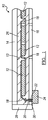
[0021]図1において、本発明の原理に従う防湿ポッティングコンパウンドを有する典型的なソーラーモジュール全体を参照番号10で示す。ソーラーモジュール10は本発明の範囲から逸脱せずに種々の形態を取ることができ、一般に第1の基板14と第2の基板16により画定されるチャンバー13の内側に配置された複数の光起電力セル12を含む。当然のことながら、任意数の光起電力セル12をソーラーモジュール10で利用することができる。
[0020] The following description is merely exemplary in nature and is not intended to limit the invention, application, or uses.
[0021] In FIG. 1, an entire exemplary solar module having a moisture-proof potting compound in accordance with the principles of the present invention is indicated by
[0022]光起電力セル12は光起電力セル12に入射する太陽光から電流を発生するように機能することが可能である。従って、光起電力セル12は本発明の範囲から逸脱せずに種々の形態を取ることができる。例えば、光起電力セル12はテルル化カドミウム(CdTe)、アモルファスシリコン、又は二セレン化銅インジウム(CuInSe2)の層を含む薄膜セルとすることができる。あるいは、光起電力セル12は結晶シリコンウェーハをラミネートフィルムに埋込んだものでもよいし、ガリウムヒ素をゲルマニウム又は別の基板に堆積させたものでもよい。利用することができる他の型の光起電力デバイス12としては、共役ポリマーと色素増感金属酸化物(湿式金属酸化物及び固体金属酸化物を含む)を併用した有機半導体セルが挙げられる。光起電力デバイス12は剛性でも可撓性でもよい。光起電力セル12は直列又は並列又はその組合せで接続される。光起電力デバイス12により発生された電流はバスバー又は他の導電材料もしくは層18を通り、第2の基板16の開口部22を通ってソーラーモジュール10の外部に延びるワイヤー又はリード線20に送られる。リード線20はソーラーモジュール10により発生された電流を電力回路に分配するために接続箱24に通じている。
[0022] The
[0023]第1の基板14ないしフロントパネルは太陽光の波長を透過させることができるように機能することが可能な材料から形成される。例えば、第1の基板14はガラス又はポリフッ化ビニル等のプラスチックフィルムである。第2の基板16ないしバックパネルはソーラーモジュール10に付加的な強度を提供するように選択される。例えば、第2の基板16はフッ化(エチレン−プロピレン)コポリマー(FEP)、ポリ(エチレン−テトラフルオロエチレンコポリマー)(ETFE)、ポリフッ化ビニリデン(PVDF)、ポリフッ化ビニル(PVF)、ポリ(テトラフルオロエチレン)(PTFE)及びこれらと他のポリマー材料の組合せ等のプラスチックである。
[0023] The
[0024]光起電力セル12は、例えば架橋性エチレン酢酸ビニル(EVA)であるラミネート層26により封入されている。しかし、当然のことながら、本発明の範囲から逸脱せずに他のラミネート又は封入材も利用することができる。ラミネート層26は光起電力デバイス12を汚染及び環境から保護するように光起電力デバイス12を部分的に封入すると共に、基板14、16を相互に接着するために使用される。
[0024] The
[0025]第1の基板14と第2の基板16の間でソーラーモジュール10の周縁部の近くにはエッジフレーム28が配置されている。エッジフレーム28は種々の幅にすることができる。エッジフレーム28はホットメルトブチル等の接着剤シーラントを使用してラミネート層26に封着される。
[0025] An
[0026]リード線20と開口部22を封止するために基板16の開口部22の内側にポッティングコンパウンド30を配置する。ポッティングコンパウンド30は水蒸気透過率(MVT)が低く、導電率が低く、塗布温度でレベリング性及びフロー性が良好である。ポッティングコンパウンド30はポッティングコンパウンド30を開口部22の内側に容易に塗布できるような粘度をもつ。ポッティングコンパウンド30は更に展性であるため、ポッティングコンパウンド30はリード線20の移動がポッティングコンパウンド30のシールを破壊しないように伸展可能である。更に、全開口部を封止して内部配線を水分侵入から保護するために接続箱24の内側にもポッティングコンパウンド30を配置する。
[0026] A
[0027]図2において、ポッティングコンパウンド30を使用する別のソーラーモジュール全体を参照番号10’で示す。ソーラーモジュール10’は第1の基板14’と第2の基板16’により画定されるチャンバー13’の内側に配置された複数の光起電力セル12’を含む。当然のことながら、任意数の光起電力セル12’をソーラーモジュール10’で利用することができる。第1の基板14’と第2の基板16’の間でソーラーモジュール10’の周縁部の近くにはエッジシール17’が配置されている。エッジシール17’は基板14’及び16’を相互に接着すると共にチャンバー13’を密封するように機能することが可能である。チャンバー13’には不活性ガスを充填することができる。
[0027] In FIG. 2, another entire solar module using a
[0028]光起電力セル12’は光起電力セル12’に入射する太陽光から電流を発生するように機能することが可能である。従って、光起電力セル12’は本発明の範囲から逸脱せずに種々の形態を取ることができる。例えば、光起電力セル12’はテルル化カドミウム(CdTe)、アモルファスシリコン、又は二セレン化銅インジウム(CuInSe2)の層を含む薄膜セルとすることができる。あるいは、光起電力セル12’は結晶シリコンウェーハをラミネートフィルムに埋込んだものでもよいし、ガリウムヒ素をゲルマニウム又は別の基板に堆積させたものでもよい。利用することができる他の型の光起電力セル12’としては、共役ポリマーと色素増感金属酸化物(湿式金属酸化物及び固体金属酸化物を含む)を併用した有機半導体セルが挙げられる。光起電力セル12’は剛性でも可撓性でもよい。光起電力セル12’は直列又は並列又はその組合せで接続される。光起電力セル12’により発生された電流はバスバー又は他の導電材料もしくは層18’を通り、エッジシール17’の開口部22’を通ってソーラーモジュール10’の外部に延びるワイヤー又はリード線20’に送られる。リード線20’は外部コネクター23’に通じている。外部コネクター23’はソーラーモジュール10’により発生された電流を電力回路に分配するために接続箱24’に通じている。接続箱24’はソーラーモジュール10’の側面又は上面に配置することができる。
[0028] The photovoltaic cell 12 'can function to generate current from sunlight incident on the photovoltaic cell 12'. Thus, the photovoltaic cell 12 'can take a variety of forms without departing from the scope of the present invention. For example, the photovoltaic cell 12 'can be a thin film cell that includes a layer of cadmium telluride (CdTe), amorphous silicon, or indium copper selenide (CuInSe 2 ). Alternatively, the photovoltaic cell 12 'may be a crystalline silicon wafer embedded in a laminate film, or gallium arsenide deposited on germanium or another substrate. Other types of photovoltaic cells 12 'that can be utilized include organic semiconductor cells that use a combination of a conjugated polymer and a dye-sensitized metal oxide (including wet metal oxides and solid metal oxides). Photovoltaic cell 12 'may be rigid or flexible. Photovoltaic cells 12 'are connected in series or parallel or a combination thereof. The current or current 20 generated by the photovoltaic cell 12 'passes through a bus bar or other conductive material or layer 18' and extends outside the solar module 10 'through the opening 22' in the edge seal 17 '. 'Sent to. The lead wire 20 'communicates with the external connector 23'. The external connector 23 'leads to the junction box 24' for distributing the current generated by the solar module 10 'to the power circuit. The
[0029]第1の基板14’ないしフロントパネルは太陽光の波長を透過させることができるように機能することが可能な材料から形成される。例えば、第1の基板14’はガラス又はポリフッ化ビニル等のプラスチックフィルムである。第2の基板16’ないしバックパネルはソーラーモジュール10’に付加的な強度を提供するように選択される。例えば、第2の基板16はフッ化(エチレン−プロピレン)コポリマー(FEP)、ポリ(エチレン−テトラフルオロエチレンコポリマー)(ETFE)、ポリフッ化ビニリデン(PVDF)、ポリフッ化ビニル(PVF)、ポリ(テトラフルオロエチレン)(PTFE)及びこれらと他のポリマー材料の組合せ等のプラスチックである。
[0029] The first substrate 14 'or front panel is formed from a material capable of functioning to transmit sunlight wavelengths. For example, the first substrate 14 'is glass or a plastic film such as polyvinyl fluoride. The second substrate 16 'or back panel is selected to provide additional strength to the solar module 10'. For example, the
[0030]光起電力セル12’は接着ストリップないし層26’によりバック基板16’に接着されている。接着ストリップ26’は本発明の範囲から逸脱せずに種々の形態を取ることができる。 [0030] The photovoltaic cell 12 'is bonded to the back substrate 16' by an adhesive strip or layer 26 '. The adhesive strip 26 'can take a variety of forms without departing from the scope of the invention.
[0031]リード線20’と開口部22’を封止するためにエッジシール17’の開口部22’の内側にポッティングコンパウンド30を配置する。ポッティングコンパウンド30は水蒸気透過率(MVT)が低く、導電率が低く、特定の粘度をもつ。更に、全開口部を封止して接続箱24の内部配線を水分侵入から保護するために接続箱24の内側にもポッティングコンパウンド30を配置することができる。
[0031] A
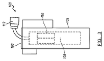
[0032]次に図3及び4において、本発明のポッティングコンパウンド30を利用するソリッドステートデバイスの別の例全体を参照番号100で示す。ソリッドステートデバイス100は本例では、地下凍結線よりも下の地下に配置することができ、家庭又は企業で水道使用量を測定するために受信機と電子通信するように機能することが可能な水道メーターである。デバイス100は一般に内側キャビティ104を画定するハウジング102を含む。ハウジング100は種々の形状及び寸法をとることができ、デバイス100の特定動作条件及び設計要件に固有の任意数のコネクター、フランジ、突起、支持部材及び補強リブを備えることができる。ハウジング102はキャビティ104を閉鎖するキャップ又は他のコンポーネント106を含む。
[0032] Referring now to FIGS. 3 and 4, another example of a solid state device utilizing the potting
[0033]ハウジング102のキャビティ104の内側にはソリッドステート回路基板108が配置されている。ソリッドステート回路基板108は固体材料から作製され、電子又は他の電荷キャリアは固体材料の内側に完全に閉じ込められる。本例では、ソリッドステート回路基板108はバッテリーパック等の電源110と、複数の回路(図示せず)に接続されたコネクター112を含む。コネクター112はキャップ106の開口部114を通ってハウジング102から外部に延びている。
[0033] A solid
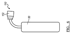
[0034]ソリッドステートデバイス100を水分侵入から防ぐために、ソリッドステート回路基板108を封入するような任意方法でポッティングコンパウンド30をソリッドステートデバイス100に塗布する。例えば、図5を参照すると、ハウジング102のキャビティ104の内側にソリッドステート回路基板108を配置した後、キャビティ104にポッティングコンパウンド30を充填する。ポッティングコンパウンド30はソリッドステート回路基板108を完全に被覆かつ封入する。図6に示す代替例では、ソリッドステート回路基板108をハウジング102の内側に配置する前にポッティングコンパウンド30で被覆する。この場合も、ポッティングコンパウンド30はソリッドステート回路基板108を完全に被覆かつ封入する。本発明の範囲から逸脱せずに、ポッティングコンパウンド30をソリッドステート回路基板108に浸し塗り、吹付塗り、又は他の方法で塗布してもよい。ポッティングコンパウンド30は約100℃〜約200℃の温度で塗布することができる。
[0034] The
[0035]上記例以外に、ポッティングコンパウンド30はタイヤ空気圧センサー、窓ガラスシール、ワイヤーシール等の任意の感湿性デバイスで使用することができる。
[0036]ポッティングコンパウンド30の組成物はオレフィン系ポリマーと、ポリエチレンワックスと、シランと、酸化防止剤と、充填剤を含有する。これらの成分は、水蒸気透過率(MVTR)、塗布温度での良好な流動性、及び使用温度(例えば125℃)で垂れ落ちないことを含む望ましい性質をもつポッティングコンパウンドを製造するようにバランスよく配合される。
[0035] In addition to the above examples, the potting
[0036] The composition of
[0037]水蒸気透過率はASTM F−1249に準じてMOCON社の試験装置により測定される。ポッティングコンパウンド30の組成物のMVTRは24時間当たり0.3g/m2未満であることが好ましい。
[0037] The water vapor transmission rate is measured by a test apparatus manufactured by MOCON according to ASTM F-1249. The MVTR of the potting
[0038]例えばソーラーモジュール用等の所定態様では、ASTM D2202−73に準じてBoeing垂れ落ち試験装置によりBoeing垂れ落ちを測定した。ポッティングコンパウンド30のBoeing垂れ落ちは125℃で約0.15インチ未満であることが好ましい。粘度はASTM D2452に準じてブルックフィールド粘度計を使用して測定した。ポッティングコンパウンド30の組成物は300°Fで約50,000cpsの粘度をもつ。
[0038] In a predetermined mode such as for a solar module, Boeing sagging was measured by a Boeing sagging test apparatus according to ASTM D2202-73. The Boeing sag of potting
[0039]本発明を更に理解し易くするために、以下の実施例を参照するが、以下の実施例は本発明を例証することを目的とし、その範囲を制限するものではない。 [0039] To make the present invention more understandable, reference is made to the following examples, which are intended to illustrate the invention and not to limit its scope.
[実施例1] [Example 1]

[実施例2] [Example 2]
[実施例3] [Example 3]
[実施例4] [Example 4]
[実施例5] [Example 5]
[実施例6]
本実施例では、ASTM D3236に準じて175℃で粘度(cp)を測定し、ASTM D2202−73に準じて125℃でBoeing垂れ落ち(インチ)を測定した。
[Example 6]
In this example, the viscosity (cp) was measured at 175 ° C. according to ASTM D3236, and Boeing sag (inch) was measured at 125 ° C. according to ASTM D2202-73.
[実施例7]
本実施例では、2枚の試験基板間に以下の処方物を塗布し、(ASTM C907に準じて)十字引張試験装置を使用してInstron装置によりその垂直引張強さを測定した。
[Example 7]
In this example, the following formulation was applied between two test substrates and the vertical tensile strength was measured with an Instron device using a cross tensile test device (according to ASTM C907).
室温で24時間;湿熱=85℃、湿度85%で1000時間;熱サイクル=200サイクル(−40℃〜85℃);及び結露凍結=10サイクル(−40℃〜85℃、湿度85%)の条件下でUL1703に準じる条件にサンプルを暴露した後に試験を行った。下表は試験の結果を示す。 24 hours at room temperature; 1000 hours at 85 ° C. and 85% humidity; thermal cycle = 200 cycles (−40 ° C. to 85 ° C.); and freezing condensation = 10 cycles (−40 ° C. to 85 ° C., humidity 85%) The test was conducted after exposing the sample to conditions according to UL 1703 under the conditions. The table below shows the results of the test.
[0040]本発明の原理によると、オレフィン系ポリマーは限定されないが、ポリイソブチレン、ポリブテン、ポリエチレン、ポリプロピレン、ポリブテン、ポリイソブテン、ブチルゴム(ポリイソブテン−イソプレン)、スチレンブロックコポリマー(変性物も含む)、及びその組合せを含む群から選択することができる。本発明の範囲から逸脱せずに他のポリオレフィン又はフッ素化ポリマーも利用できる。好ましい1態様において、オレフィン系ポリマーはポリイソブチレンとポリブテンを含む。 [0040] According to the principles of the present invention, olefinic polymers are not limited, but include polyisobutylene, polybutene, polyethylene, polypropylene, polybutene, polyisobutene, butyl rubber (polyisobutene-isoprene), styrene block copolymers (including modified), and the like It can be selected from the group comprising combinations. Other polyolefins or fluorinated polymers can be utilized without departing from the scope of the present invention. In a preferred embodiment, the olefinic polymer comprises polyisobutylene and polybutene.
[0041]ポリエチレンワックスの代わりに軟化点/融点が約50℃〜約200℃の任意ワックスを使用してもよい。
[0042]酸化防止剤は限定されないが、テトラキス[メチレン(3,5−ジ−tert−ブチルヒドロキシヒドロシンナメート)]メタン、ヒンダードフェノール、ヒンダードアミン、チオエーテル、メルカプト化合物、亜リン酸エステル、ベンゾトリアゾール、ベンゾフェノン、オゾン劣化防止剤、及びその組合せを含む群から選択することができる。好ましい1態様において、酸化防止剤はテトラキス[メチレン(3,5−ジ−tert−ブチルヒドロキシヒドロシンナメート)]メタンを含む。
[0041] An optional wax having a softening point / melting point of about 50 ° C. to about 200 ° C. may be used in place of the polyethylene wax.
[0042] The antioxidant is not limited, but tetrakis [methylene (3,5-di-tert-butylhydroxyhydrocinnamate)] methane, hindered phenol, hindered amine, thioether, mercapto compound, phosphite, benzotriazole , Benzophenone, antiozonants, and combinations thereof. In a preferred embodiment, the antioxidant comprises tetrakis [methylene (3,5-di-tert-butylhydroxyhydrocinnamate)] methane.
[0043]シランは限定されないが、3−(2−アミノエチル)アミノプロプルトリメトキシシラン、DFDA−5451NT(Dow Chemical製シラングラフトPE)、DFDA−5481NT(Dow Chemical製 湿気硬化型触媒)、非晶性ポリαオレフィン(例えばVestoplast 206、Vestoplast 2412)、アルコキシシラン、アミノシラン、及びその組合せを含む群から選択することができる。好ましい1態様において、シランは3−(2−アミノエチル)アミノプロピルトリメトキシシランを含む。 [0043] Silane is not limited, but 3- (2-aminoethyl) aminopropyltrimethoxysilane, DFDA-5451NT (Dow Chemical silane graft PE), DFDA-5281NT (Dow Chemical moisture-curing catalyst), non- Crystalline polyalphaolefins (eg, Vestplast 206, Vestplast 2412), alkoxysilanes, aminosilanes, and combinations thereof can be selected. In a preferred embodiment, the silane comprises 3- (2-aminoethyl) aminopropyltrimethoxysilane.
[0044]カーボンブラックは着色用に使用され、変更又は省略してもよい。例えば、本発明の範囲から逸脱せずに顔料として二酸化チタンを使用することができる。
[0045]更に、本発明から逸脱せずにミシシッピライム等の水分捕捉剤、又はモレキュラーシーブもしくは無水無機塩等の乾燥剤も配合することができる。
[0044] Carbon black is used for coloring and may be modified or omitted. For example, titanium dioxide can be used as a pigment without departing from the scope of the present invention.
[0045] Furthermore, moisture scavengers such as Mississippi lime, or desiccants such as molecular sieves or anhydrous inorganic salts can be blended without departing from the present invention.
[0046]以上の本発明の説明は本質的に例示に過ぎず、本発明の要旨から逸脱しない変形も本発明の範囲に含むものとする。このような変形は本発明の趣旨及び範囲から逸脱するとみなすべきではない。 [0046] The above description of the present invention is merely illustrative in nature, and modifications that do not depart from the gist of the present invention are intended to be included in the scope of the present invention. Such variations are not to be regarded as a departure from the spirit and scope of the present invention.
Claims (20)
b)コンパウンド全体の約0.1〜約15重量%の量で配合された少なくとも1種のシランと;
c)コンパウンド全体の約2〜約30重量%の量で配合された少なくとも1種のワックスと;
d)コンパウンド全体の約0.1〜約4重量%の量で配合された少なくとも1種の酸化防止剤と;
e)コンパウンド全体の約0.1〜約20重量%の量で配合された少なくとも1種の充填剤
を含有する防湿ポッティングコンパウンド。 a) at least one olefinic polymer compounded in an amount of about 40 to about 95 weight percent of the total compound;
b) at least one silane formulated in an amount of about 0.1 to about 15% by weight of the total compound;
c) at least one wax formulated in an amount of from about 2 to about 30% by weight of the total compound;
d) at least one antioxidant formulated in an amount of about 0.1 to about 4% by weight of the total compound;
e) A moisture-proof potting compound containing at least one filler formulated in an amount of about 0.1 to about 20% by weight of the total compound.
第2の基板と;
第1の基板と第2の基板の間に配置された少なくとも1個の光起電力セルであって、前記少なくとも1個の光起電力セルにより発生された電流がソーラーモジュールの開口部を通って外部に延びるリード線に送られるように構成された前記少なくとも1個の光起電力セルと;
リード線と開口部を封止するようにソーラーモジュールの開口部の内側に配置されたポッティングコンパウンド
を含むソーラーモジュールであって、前記ポッティングコンパウンドが、
少なくとも1種のオレフィン系ポリマーと;
少なくとも1種のシランと;
少なくとも1種のワックスと;
少なくとも1種の酸化防止剤と;
少なくとも1種の充填剤
を含有する前記ソーラーモジュール。 A first substrate;
A second substrate;
At least one photovoltaic cell disposed between the first substrate and the second substrate, wherein the current generated by the at least one photovoltaic cell passes through the opening of the solar module; The at least one photovoltaic cell configured to be routed to an externally extending lead;
A solar module including a potting compound disposed inside the opening of the solar module so as to seal the lead wire and the opening, the potting compound comprising:
At least one olefinic polymer;
At least one silane;
At least one wax;
At least one antioxidant;
Said solar module comprising at least one filler.
ハウジングの内側に配置された回路基板と;
回路基板を水分侵入から防ぐために防湿バリアを形成するように回路基板を封入するポッティングコンパウンド
を含むソリッドステートデバイスであって、前記ポッティングコンパウンドが、
少なくとも1種のオレフィン系ポリマーと;
少なくとも1種のシランと;
少なくとも1種のワックスと;
少なくとも1種の酸化防止剤と;
少なくとも1種の充填剤
を含有する前記ソリッドステートデバイス。 A housing defining an inner cavity;
A circuit board disposed inside the housing;
A solid state device including a potting compound that encapsulates a circuit board to form a moisture barrier to prevent the circuit board from moisture ingress, the potting compound comprising:
At least one olefinic polymer;
At least one silane;
At least one wax;
At least one antioxidant;
Said solid state device comprising at least one filler.
Applications Claiming Priority (3)
| Application Number | Priority Date | Filing Date | Title |
|---|---|---|---|
| US30059510P | 2010-02-02 | 2010-02-02 | |
| US61/300,595 | 2010-02-02 | ||
| PCT/US2010/060297 WO2011096986A1 (en) | 2010-02-02 | 2010-12-14 | Moisture barrier potting compound |
Publications (2)
| Publication Number | Publication Date |
|---|---|
| JP2013518971A true JP2013518971A (en) | 2013-05-23 |
| JP2013518971A5 JP2013518971A5 (en) | 2013-09-26 |
Family
ID=44355710
Family Applications (1)
| Application Number | Title | Priority Date | Filing Date |
|---|---|---|---|
| JP2012551969A Pending JP2013518971A (en) | 2010-02-02 | 2010-12-14 | Moisture-proof potting compound |
Country Status (6)
| Country | Link |
|---|---|
| US (1) | US20120302685A1 (en) |
| EP (1) | EP2532025A4 (en) |
| JP (1) | JP2013518971A (en) |
| KR (1) | KR20120114395A (en) |
| CN (1) | CN102939651A (en) |
| WO (1) | WO2011096986A1 (en) |
Cited By (1)
| Publication number | Priority date | Publication date | Assignee | Title |
|---|---|---|---|---|
| JP2016089098A (en) * | 2014-11-07 | 2016-05-23 | アイカ工業株式会社 | Yellowing-resistant hot melt sealing composition |
Families Citing this family (5)
| Publication number | Priority date | Publication date | Assignee | Title |
|---|---|---|---|---|
| US8894754B2 (en) * | 2011-08-10 | 2014-11-25 | Semprius, Inc. | Breathing and desiccant regenerating cycle for reducing condensation in concentrator photovoltaic modules |
| JP2014212313A (en) * | 2013-04-05 | 2014-11-13 | 日東電工株式会社 | Solar cell panel end sealing composition, solar cell panel end sealing sheet, and solar cell panel |
| DE102016003487B4 (en) * | 2016-03-24 | 2020-03-12 | Azur Space Solar Power Gmbh | Solar cell unit and solar cell module |
| EP3754729B8 (en) * | 2018-02-14 | 2024-01-24 | Shangrao Xinyuan YueDong Technology Development Co. Ltd | Solar cell module comprising perovskite solar cell and manufacturing method thereof |
| KR102543008B1 (en) * | 2018-05-30 | 2023-06-14 | 상라오 징코 솔라 테크놀러지 디벨롭먼트 컴퍼니, 리미티드 | Solar cell module contaning perovskite eolar cell and manufacturing method for the same |
Citations (3)
| Publication number | Priority date | Publication date | Assignee | Title |
|---|---|---|---|---|
| JP2002037948A (en) * | 2000-07-25 | 2002-02-06 | Mitsui Chemicals Inc | Curable composition and application thereof |
| US20030162882A1 (en) * | 2000-03-28 | 2003-08-28 | Stefan Grimm | Reactive hot-melt-type adhesive granulate for insulating glass |
| WO2008005214A2 (en) * | 2006-07-03 | 2008-01-10 | Dow Corning Corporation | Chemically curing all-in-one warm edge spacer and seal |
Family Cites Families (12)
| Publication number | Priority date | Publication date | Assignee | Title |
|---|---|---|---|---|
| US4529755A (en) * | 1982-10-23 | 1985-07-16 | Denki Kagaku Kogyo Kabushiki Kaisha | Epoxy resin composition for encapsulating semiconductor |
| JPH11317475A (en) * | 1998-02-27 | 1999-11-16 | Canon Inc | Encapsulating material resin for semiconductor and semiconductor element |
| CN100480324C (en) * | 2000-07-25 | 2009-04-22 | 三井化学株式会社 | Curable composition and uses thereof |
| US6544596B2 (en) * | 2000-11-29 | 2003-04-08 | Pacific Northwest Coatings | Method of coating a substrate using a thermosetting basecoat composition and a thermoplastic top coat composition |
| WO2004090033A1 (en) * | 2003-04-07 | 2004-10-21 | Hitachi Chemical Co., Ltd. | Epoxy resin molding material for sealing use and semiconductor device |
| FR2859814A1 (en) * | 2003-09-12 | 2005-03-18 | Nexans | Electrically-insulating and heat-resistant composition, especially for use in security cables for power or telecommunications, contains organic polymer, phyllosilicate and refractory filler |
| WO2005095475A1 (en) * | 2004-03-24 | 2005-10-13 | Exxonmobil Chemical Patents Inc. | Process for making ethylene interpolymers and interpolymers made thereby; compositions and electrical devices containing such interpolymers |
| US8053086B2 (en) * | 2005-03-08 | 2011-11-08 | Du Pont-Mitsui Polychemicals Co., Ltd. | Encapsulating material for solar cell |
| US8089062B2 (en) * | 2005-03-23 | 2012-01-03 | Xerox Corporation | Wax encapsulated electronic devices |
| WO2006103962A1 (en) * | 2005-03-25 | 2006-10-05 | Sumitomo Bakelite Co., Ltd. | Semiconductor device, resin composition for buffer coating, resin composition for die bonding, and resin composition for encapsulation |
| JP2008019403A (en) * | 2006-07-14 | 2008-01-31 | Jsr Corp | Oxide fine particle-containing resin composition and method for producing the same |
| US20090159117A1 (en) * | 2007-12-20 | 2009-06-25 | Truseal Technologies, Inc. | Hot melt sealant containing desiccant for use in photovoltaic modules |
-
2010
- 2010-12-14 EP EP10845410.9A patent/EP2532025A4/en not_active Withdrawn
- 2010-12-14 CN CN2010800659748A patent/CN102939651A/en active Pending
- 2010-12-14 US US13/575,876 patent/US20120302685A1/en not_active Abandoned
- 2010-12-14 KR KR1020127022948A patent/KR20120114395A/en not_active Application Discontinuation
- 2010-12-14 JP JP2012551969A patent/JP2013518971A/en active Pending
- 2010-12-14 WO PCT/US2010/060297 patent/WO2011096986A1/en active Application Filing
Patent Citations (3)
| Publication number | Priority date | Publication date | Assignee | Title |
|---|---|---|---|---|
| US20030162882A1 (en) * | 2000-03-28 | 2003-08-28 | Stefan Grimm | Reactive hot-melt-type adhesive granulate for insulating glass |
| JP2002037948A (en) * | 2000-07-25 | 2002-02-06 | Mitsui Chemicals Inc | Curable composition and application thereof |
| WO2008005214A2 (en) * | 2006-07-03 | 2008-01-10 | Dow Corning Corporation | Chemically curing all-in-one warm edge spacer and seal |
Cited By (1)
| Publication number | Priority date | Publication date | Assignee | Title |
|---|---|---|---|---|
| JP2016089098A (en) * | 2014-11-07 | 2016-05-23 | アイカ工業株式会社 | Yellowing-resistant hot melt sealing composition |
Also Published As
| Publication number | Publication date |
|---|---|
| WO2011096986A1 (en) | 2011-08-11 |
| EP2532025A1 (en) | 2012-12-12 |
| US20120302685A1 (en) | 2012-11-29 |
| EP2532025A4 (en) | 2013-07-17 |
| KR20120114395A (en) | 2012-10-16 |
| CN102939651A (en) | 2013-02-20 |
Similar Documents
| Publication | Publication Date | Title |
|---|---|---|
| US20120192946A1 (en) | Use of calcium oxide as a water scavenger in solar applications | |
| JP2013518971A (en) | Moisture-proof potting compound | |
| JP2013509694A (en) | Edge sealant composition containing a reactive or unsaturated polyolefin | |
| JP2013509453A (en) | Use of calcium oxide as a moisture scavenger in solar module applications | |
| Kempe et al. | Acetic acid production and glass transition concerns with ethylene-vinyl acetate used in photovoltaic devices | |
| TWI550005B (en) | Solar cell sealing material, and solar cell module | |
| CN102804440B (en) | Organic electronic device and manufacture method thereof | |
| CN102362352B (en) | Optoelectronic device | |
| CN103038893A (en) | Solar cell sealing material, and solar cell module prepared by using same | |
| TW201002796A (en) | Adhesive encapsulating composition and electronic devices made therewith | |
| CN103081121A (en) | Solar cell sealing material and solar cell module produced by using same | |
| US20110197955A1 (en) | Solar module having an encapsulant mounting adhesive | |
| KR101701690B1 (en) | Resin composition for solar cell sealing materials, master batch for solar cell sealing materials, and solar cell sealing material | |
| US20120199199A1 (en) | Edge sealant composition with reactive or unsaturated polyolefins | |
| US20160308081A1 (en) | Solar cell module | |
| CN103477444A (en) | Surface protective material for solar cell, and solar cell module produced using same | |
| CN104245820A (en) | Sealant composition | |
| CN103890967A (en) | Sealing film for solar cells, and solar cell using same | |
| US20120085408A1 (en) | Solar module sealant | |
| US20120240981A1 (en) | Weatherable layer for photovoltaic module | |
| US20110226334A1 (en) | Solar module sealant | |
| JP2013522879A (en) | Photovoltaic module with buffer layer | |
| CN106796989A (en) | Solar cell | |
| JP6686430B2 (en) | Encapsulant sheet for solar cell module and solar cell module using the same | |
| CN107078220A (en) | Solar cell |
Legal Events
| Date | Code | Title | Description |
|---|---|---|---|
| A521 | Request for written amendment filed |
Free format text: JAPANESE INTERMEDIATE CODE: A523 Effective date: 20130812 |
|
| A621 | Written request for application examination |
Free format text: JAPANESE INTERMEDIATE CODE: A621 Effective date: 20130812 |
|
| A977 | Report on retrieval |
Free format text: JAPANESE INTERMEDIATE CODE: A971007 Effective date: 20140131 |
|
| A131 | Notification of reasons for refusal |
Free format text: JAPANESE INTERMEDIATE CODE: A131 Effective date: 20140205 |
|
| A521 | Request for written amendment filed |
Free format text: JAPANESE INTERMEDIATE CODE: A523 Effective date: 20140502 |
|
| A02 | Decision of refusal |
Free format text: JAPANESE INTERMEDIATE CODE: A02 Effective date: 20140822 |