JP2013515902A - Exhaust system for vehicle positive ignition internal combustion engine - Google Patents
Exhaust system for vehicle positive ignition internal combustion engine Download PDFInfo
- Publication number
- JP2013515902A JP2013515902A JP2012545454A JP2012545454A JP2013515902A JP 2013515902 A JP2013515902 A JP 2013515902A JP 2012545454 A JP2012545454 A JP 2012545454A JP 2012545454 A JP2012545454 A JP 2012545454A JP 2013515902 A JP2013515902 A JP 2013515902A
- Authority
- JP
- Japan
- Prior art keywords
- washcoat
- filter
- exhaust system
- pore size
- average pore
- Prior art date
- Legal status (The legal status is an assumption and is not a legal conclusion. Google has not performed a legal analysis and makes no representation as to the accuracy of the status listed.)
- Pending
Links
- 238000002485 combustion reaction Methods 0.000 title claims abstract description 23
- 239000000758 substrate Substances 0.000 claims abstract description 140
- 239000011148 porous material Substances 0.000 claims abstract description 138
- 239000002245 particle Substances 0.000 claims abstract description 104
- 239000003054 catalyst Substances 0.000 claims abstract description 103
- 239000013618 particulate matter Substances 0.000 claims abstract description 76
- 238000011144 upstream manufacturing Methods 0.000 claims abstract description 39
- 238000001914 filtration Methods 0.000 claims abstract description 22
- 239000007787 solid Substances 0.000 claims abstract description 18
- 238000000034 method Methods 0.000 claims description 21
- 229910052751 metal Inorganic materials 0.000 claims description 17
- 239000002184 metal Substances 0.000 claims description 17
- 239000000919 ceramic Substances 0.000 claims description 10
- 238000011118 depth filtration Methods 0.000 claims description 7
- 239000006260 foam Substances 0.000 claims description 3
- 238000000926 separation method Methods 0.000 abstract description 2
- 239000007789 gas Substances 0.000 description 101
- 229930195733 hydrocarbon Natural products 0.000 description 55
- 150000002430 hydrocarbons Chemical class 0.000 description 50
- UGFAIRIUMAVXCW-UHFFFAOYSA-N Carbon monoxide Chemical compound [O+]#[C-] UGFAIRIUMAVXCW-UHFFFAOYSA-N 0.000 description 35
- 229910002091 carbon monoxide Inorganic materials 0.000 description 35
- 239000000446 fuel Substances 0.000 description 32
- MWUXSHHQAYIFBG-UHFFFAOYSA-N nitrogen oxide Inorganic materials O=[N] MWUXSHHQAYIFBG-UHFFFAOYSA-N 0.000 description 29
- KDLHZDBZIXYQEI-UHFFFAOYSA-N Palladium Chemical compound [Pd] KDLHZDBZIXYQEI-UHFFFAOYSA-N 0.000 description 27
- 238000006243 chemical reaction Methods 0.000 description 27
- 239000000203 mixture Substances 0.000 description 26
- 239000010410 layer Substances 0.000 description 25
- 239000011248 coating agent Substances 0.000 description 22
- 238000000576 coating method Methods 0.000 description 22
- BASFCYQUMIYNBI-UHFFFAOYSA-N platinum Chemical compound [Pt] BASFCYQUMIYNBI-UHFFFAOYSA-N 0.000 description 21
- 229910052760 oxygen Inorganic materials 0.000 description 20
- 230000009467 reduction Effects 0.000 description 20
- 238000006722 reduction reaction Methods 0.000 description 20
- QVGXLLKOCUKJST-UHFFFAOYSA-N atomic oxygen Chemical compound [O] QVGXLLKOCUKJST-UHFFFAOYSA-N 0.000 description 19
- 239000001301 oxygen Substances 0.000 description 19
- 239000003570 air Substances 0.000 description 18
- 230000000694 effects Effects 0.000 description 18
- 238000002347 injection Methods 0.000 description 17
- 239000007924 injection Substances 0.000 description 17
- 239000000463 material Substances 0.000 description 16
- 239000004215 Carbon black (E152) Substances 0.000 description 15
- 230000003647 oxidation Effects 0.000 description 15
- 238000007254 oxidation reaction Methods 0.000 description 15
- 238000009826 distribution Methods 0.000 description 13
- 229910000510 noble metal Inorganic materials 0.000 description 13
- -1 platinum group metals Chemical class 0.000 description 13
- 239000010948 rhodium Substances 0.000 description 12
- 229910052763 palladium Inorganic materials 0.000 description 10
- 229910052697 platinum Inorganic materials 0.000 description 10
- 239000003638 chemical reducing agent Substances 0.000 description 9
- 229910052878 cordierite Inorganic materials 0.000 description 9
- JSKIRARMQDRGJZ-UHFFFAOYSA-N dimagnesium dioxido-bis[(1-oxido-3-oxo-2,4,6,8,9-pentaoxa-1,3-disila-5,7-dialuminabicyclo[3.3.1]nonan-7-yl)oxy]silane Chemical compound [Mg++].[Mg++].[O-][Si]([O-])(O[Al]1O[Al]2O[Si](=O)O[Si]([O-])(O1)O2)O[Al]1O[Al]2O[Si](=O)O[Si]([O-])(O1)O2 JSKIRARMQDRGJZ-UHFFFAOYSA-N 0.000 description 9
- 238000003860 storage Methods 0.000 description 9
- QGZKDVFQNNGYKY-UHFFFAOYSA-N Ammonia Chemical compound N QGZKDVFQNNGYKY-UHFFFAOYSA-N 0.000 description 8
- CURLTUGMZLYLDI-UHFFFAOYSA-N Carbon dioxide Chemical compound O=C=O CURLTUGMZLYLDI-UHFFFAOYSA-N 0.000 description 8
- 230000003197 catalytic effect Effects 0.000 description 8
- 229910052703 rhodium Inorganic materials 0.000 description 8
- 238000012360 testing method Methods 0.000 description 8
- 210000004027 cell Anatomy 0.000 description 7
- 210000002421 cell wall Anatomy 0.000 description 7
- MHOVAHRLVXNVSD-UHFFFAOYSA-N rhodium atom Chemical compound [Rh] MHOVAHRLVXNVSD-UHFFFAOYSA-N 0.000 description 7
- OKKJLVBELUTLKV-UHFFFAOYSA-N Methanol Chemical compound OC OKKJLVBELUTLKV-UHFFFAOYSA-N 0.000 description 6
- QAOWNCQODCNURD-UHFFFAOYSA-N Sulfuric acid Chemical compound OS(O)(=O)=O QAOWNCQODCNURD-UHFFFAOYSA-N 0.000 description 6
- 230000008901 benefit Effects 0.000 description 6
- 238000006073 displacement reaction Methods 0.000 description 6
- 229910018072 Al 2 O 3 Inorganic materials 0.000 description 5
- 238000009825 accumulation Methods 0.000 description 5
- 229910052788 barium Inorganic materials 0.000 description 5
- DSAJWYNOEDNPEQ-UHFFFAOYSA-N barium atom Chemical compound [Ba] DSAJWYNOEDNPEQ-UHFFFAOYSA-N 0.000 description 5
- 230000015572 biosynthetic process Effects 0.000 description 5
- 238000013461 design Methods 0.000 description 5
- VNWKTOKETHGBQD-UHFFFAOYSA-N methane Natural products C VNWKTOKETHGBQD-UHFFFAOYSA-N 0.000 description 5
- 239000002105 nanoparticle Substances 0.000 description 5
- 239000004071 soot Substances 0.000 description 5
- 239000002344 surface layer Substances 0.000 description 5
- 239000011882 ultra-fine particle Substances 0.000 description 5
- IJGRMHOSHXDMSA-UHFFFAOYSA-N Atomic nitrogen Chemical compound N#N IJGRMHOSHXDMSA-UHFFFAOYSA-N 0.000 description 4
- LFQSCWFLJHTTHZ-UHFFFAOYSA-N Ethanol Chemical compound CCO LFQSCWFLJHTTHZ-UHFFFAOYSA-N 0.000 description 4
- 229910052783 alkali metal Inorganic materials 0.000 description 4
- 150000001340 alkali metals Chemical class 0.000 description 4
- 229910021529 ammonia Inorganic materials 0.000 description 4
- 229910002092 carbon dioxide Inorganic materials 0.000 description 4
- 239000001569 carbon dioxide Substances 0.000 description 4
- 238000006555 catalytic reaction Methods 0.000 description 4
- 238000010790 dilution Methods 0.000 description 4
- 239000012895 dilution Substances 0.000 description 4
- HNPSIPDUKPIQMN-UHFFFAOYSA-N dioxosilane;oxo(oxoalumanyloxy)alumane Chemical compound O=[Si]=O.O=[Al]O[Al]=O HNPSIPDUKPIQMN-UHFFFAOYSA-N 0.000 description 4
- 239000003344 environmental pollutant Substances 0.000 description 4
- 238000009472 formulation Methods 0.000 description 4
- 230000007246 mechanism Effects 0.000 description 4
- QSHDDOUJBYECFT-UHFFFAOYSA-N mercury Chemical compound [Hg] QSHDDOUJBYECFT-UHFFFAOYSA-N 0.000 description 4
- 229910052753 mercury Inorganic materials 0.000 description 4
- 231100000719 pollutant Toxicity 0.000 description 4
- 239000002243 precursor Substances 0.000 description 4
- 230000008569 process Effects 0.000 description 4
- XLYOFNOQVPJJNP-UHFFFAOYSA-N water Substances O XLYOFNOQVPJJNP-UHFFFAOYSA-N 0.000 description 4
- 239000010457 zeolite Substances 0.000 description 4
- 229910052684 Cerium Inorganic materials 0.000 description 3
- 229910021536 Zeolite Inorganic materials 0.000 description 3
- 239000002250 absorbent Substances 0.000 description 3
- 230000002745 absorbent Effects 0.000 description 3
- 229910052784 alkaline earth metal Inorganic materials 0.000 description 3
- 150000001342 alkaline earth metals Chemical class 0.000 description 3
- 230000004323 axial length Effects 0.000 description 3
- 238000001354 calcination Methods 0.000 description 3
- GWXLDORMOJMVQZ-UHFFFAOYSA-N cerium Chemical compound [Ce] GWXLDORMOJMVQZ-UHFFFAOYSA-N 0.000 description 3
- 238000007906 compression Methods 0.000 description 3
- 230000006835 compression Effects 0.000 description 3
- 229910052802 copper Inorganic materials 0.000 description 3
- 230000008878 coupling Effects 0.000 description 3
- 238000010168 coupling process Methods 0.000 description 3
- 238000005859 coupling reaction Methods 0.000 description 3
- 238000000151 deposition Methods 0.000 description 3
- 230000008021 deposition Effects 0.000 description 3
- 239000000428 dust Substances 0.000 description 3
- 230000012010 growth Effects 0.000 description 3
- 229910052742 iron Inorganic materials 0.000 description 3
- 238000004519 manufacturing process Methods 0.000 description 3
- 238000005259 measurement Methods 0.000 description 3
- 229910052759 nickel Inorganic materials 0.000 description 3
- 229910052757 nitrogen Inorganic materials 0.000 description 3
- QJGQUHMNIGDVPM-UHFFFAOYSA-N nitrogen group Chemical group [N] QJGQUHMNIGDVPM-UHFFFAOYSA-N 0.000 description 3
- 229920000642 polymer Polymers 0.000 description 3
- 238000001179 sorption measurement Methods 0.000 description 3
- 241000894007 species Species 0.000 description 3
- 239000000126 substance Substances 0.000 description 3
- 230000005653 Brownian motion process Effects 0.000 description 2
- OKTJSMMVPCPJKN-UHFFFAOYSA-N Carbon Chemical compound [C] OKTJSMMVPCPJKN-UHFFFAOYSA-N 0.000 description 2
- 239000004372 Polyvinyl alcohol Substances 0.000 description 2
- ATUOYWHBWRKTHZ-UHFFFAOYSA-N Propane Chemical compound CCC ATUOYWHBWRKTHZ-UHFFFAOYSA-N 0.000 description 2
- 229910010413 TiO 2 Inorganic materials 0.000 description 2
- 239000012080 ambient air Substances 0.000 description 2
- 239000002585 base Substances 0.000 description 2
- 230000002902 bimodal effect Effects 0.000 description 2
- 230000033228 biological regulation Effects 0.000 description 2
- 238000005537 brownian motion Methods 0.000 description 2
- 229910052799 carbon Inorganic materials 0.000 description 2
- 238000010531 catalytic reduction reaction Methods 0.000 description 2
- 229910000420 cerium oxide Inorganic materials 0.000 description 2
- 239000000356 contaminant Substances 0.000 description 2
- 238000000354 decomposition reaction Methods 0.000 description 2
- 230000007423 decrease Effects 0.000 description 2
- 238000011161 development Methods 0.000 description 2
- 230000018109 developmental process Effects 0.000 description 2
- KZHJGOXRZJKJNY-UHFFFAOYSA-N dioxosilane;oxo(oxoalumanyloxy)alumane Chemical compound O=[Si]=O.O=[Si]=O.O=[Al]O[Al]=O.O=[Al]O[Al]=O.O=[Al]O[Al]=O KZHJGOXRZJKJNY-UHFFFAOYSA-N 0.000 description 2
- 238000001035 drying Methods 0.000 description 2
- 238000002474 experimental method Methods 0.000 description 2
- 239000010419 fine particle Substances 0.000 description 2
- 229910052733 gallium Inorganic materials 0.000 description 2
- 229910052738 indium Inorganic materials 0.000 description 2
- 229910052746 lanthanum Inorganic materials 0.000 description 2
- 239000007788 liquid Substances 0.000 description 2
- 229910052748 manganese Inorganic materials 0.000 description 2
- VUZPPFZMUPKLLV-UHFFFAOYSA-N methane;hydrate Chemical compound C.O VUZPPFZMUPKLLV-UHFFFAOYSA-N 0.000 description 2
- 239000011859 microparticle Substances 0.000 description 2
- 229910052863 mullite Inorganic materials 0.000 description 2
- 230000006911 nucleation Effects 0.000 description 2
- 238000010899 nucleation Methods 0.000 description 2
- 230000001590 oxidative effect Effects 0.000 description 2
- 229920002451 polyvinyl alcohol Polymers 0.000 description 2
- 230000008929 regeneration Effects 0.000 description 2
- 238000011069 regeneration method Methods 0.000 description 2
- 238000005070 sampling Methods 0.000 description 2
- 229910052720 vanadium Inorganic materials 0.000 description 2
- 239000011800 void material Substances 0.000 description 2
- 238000009736 wetting Methods 0.000 description 2
- 229910052725 zinc Inorganic materials 0.000 description 2
- 229910000505 Al2TiO5 Inorganic materials 0.000 description 1
- 241000269350 Anura Species 0.000 description 1
- 229910020203 CeO Inorganic materials 0.000 description 1
- 229920000742 Cotton Polymers 0.000 description 1
- UFHFLCQGNIYNRP-UHFFFAOYSA-N Hydrogen Chemical compound [H][H] UFHFLCQGNIYNRP-UHFFFAOYSA-N 0.000 description 1
- 229910002651 NO3 Inorganic materials 0.000 description 1
- NHNBFGGVMKEFGY-UHFFFAOYSA-N Nitrate Chemical compound [O-][N+]([O-])=O NHNBFGGVMKEFGY-UHFFFAOYSA-N 0.000 description 1
- GRYLNZFGIOXLOG-UHFFFAOYSA-N Nitric acid Chemical compound O[N+]([O-])=O GRYLNZFGIOXLOG-UHFFFAOYSA-N 0.000 description 1
- 229910052581 Si3N4 Inorganic materials 0.000 description 1
- 229910004298 SiO 2 Inorganic materials 0.000 description 1
- NINIDFKCEFEMDL-UHFFFAOYSA-N Sulfur Chemical compound [S] NINIDFKCEFEMDL-UHFFFAOYSA-N 0.000 description 1
- XSQUKJJJFZCRTK-UHFFFAOYSA-N Urea Chemical compound NC(N)=O XSQUKJJJFZCRTK-UHFFFAOYSA-N 0.000 description 1
- QCWXUUIWCKQGHC-UHFFFAOYSA-N Zirconium Chemical compound [Zr] QCWXUUIWCKQGHC-UHFFFAOYSA-N 0.000 description 1
- 230000004913 activation Effects 0.000 description 1
- 239000004480 active ingredient Substances 0.000 description 1
- 230000002411 adverse Effects 0.000 description 1
- PNEYBMLMFCGWSK-UHFFFAOYSA-N aluminium oxide Inorganic materials [O-2].[O-2].[O-2].[Al+3].[Al+3] PNEYBMLMFCGWSK-UHFFFAOYSA-N 0.000 description 1
- 229910000323 aluminium silicate Inorganic materials 0.000 description 1
- BVCZEBOGSOYJJT-UHFFFAOYSA-N ammonium carbamate Chemical compound [NH4+].NC([O-])=O BVCZEBOGSOYJJT-UHFFFAOYSA-N 0.000 description 1
- VZTDIZULWFCMLS-UHFFFAOYSA-N ammonium formate Chemical compound [NH4+].[O-]C=O VZTDIZULWFCMLS-UHFFFAOYSA-N 0.000 description 1
- 230000004888 barrier function Effects 0.000 description 1
- 239000006227 byproduct Substances 0.000 description 1
- 239000004202 carbamide Substances 0.000 description 1
- 150000004649 carbonic acid derivatives Chemical class 0.000 description 1
- KXDHJXZQYSOELW-UHFFFAOYSA-N carbonic acid monoamide Natural products NC(O)=O KXDHJXZQYSOELW-UHFFFAOYSA-N 0.000 description 1
- 229910010293 ceramic material Inorganic materials 0.000 description 1
- 230000008859 change Effects 0.000 description 1
- 239000007809 chemical reaction catalyst Substances 0.000 description 1
- 239000013626 chemical specie Substances 0.000 description 1
- 229910052804 chromium Inorganic materials 0.000 description 1
- 238000005056 compaction Methods 0.000 description 1
- 230000000295 complement effect Effects 0.000 description 1
- 239000002131 composite material Substances 0.000 description 1
- 238000005094 computer simulation Methods 0.000 description 1
- PMHQVHHXPFUNSP-UHFFFAOYSA-M copper(1+);methylsulfanylmethane;bromide Chemical compound Br[Cu].CSC PMHQVHHXPFUNSP-UHFFFAOYSA-M 0.000 description 1
- 230000034994 death Effects 0.000 description 1
- 230000003247 decreasing effect Effects 0.000 description 1
- 230000001627 detrimental effect Effects 0.000 description 1
- 238000009792 diffusion process Methods 0.000 description 1
- 230000007613 environmental effect Effects 0.000 description 1
- 230000002349 favourable effect Effects 0.000 description 1
- 229910001657 ferrierite group Inorganic materials 0.000 description 1
- 239000012065 filter cake Substances 0.000 description 1
- 229910052737 gold Inorganic materials 0.000 description 1
- 239000010931 gold Substances 0.000 description 1
- 229910052735 hafnium Inorganic materials 0.000 description 1
- 230000036541 health Effects 0.000 description 1
- 239000001257 hydrogen Substances 0.000 description 1
- 229910052739 hydrogen Inorganic materials 0.000 description 1
- 230000007062 hydrolysis Effects 0.000 description 1
- 238000006460 hydrolysis reaction Methods 0.000 description 1
- 150000004679 hydroxides Chemical class 0.000 description 1
- 238000011065 in-situ storage Methods 0.000 description 1
- 229910001959 inorganic nitrate Inorganic materials 0.000 description 1
- 238000009434 installation Methods 0.000 description 1
- 230000003993 interaction Effects 0.000 description 1
- 238000009533 lab test Methods 0.000 description 1
- FZLIPJUXYLNCLC-UHFFFAOYSA-N lanthanum atom Chemical compound [La] FZLIPJUXYLNCLC-UHFFFAOYSA-N 0.000 description 1
- 210000004072 lung Anatomy 0.000 description 1
- 238000000691 measurement method Methods 0.000 description 1
- 229910044991 metal oxide Inorganic materials 0.000 description 1
- 150000004706 metal oxides Chemical class 0.000 description 1
- 239000006262 metallic foam Substances 0.000 description 1
- 238000001465 metallisation Methods 0.000 description 1
- 229910052680 mordenite Inorganic materials 0.000 description 1
- 150000002823 nitrates Chemical class 0.000 description 1
- 229910017604 nitric acid Inorganic materials 0.000 description 1
- QGLKJKCYBOYXKC-UHFFFAOYSA-N nonaoxidotritungsten Chemical compound O=[W]1(=O)O[W](=O)(=O)O[W](=O)(=O)O1 QGLKJKCYBOYXKC-UHFFFAOYSA-N 0.000 description 1
- TVMXDCGIABBOFY-UHFFFAOYSA-N octane Chemical compound CCCCCCCC TVMXDCGIABBOFY-UHFFFAOYSA-N 0.000 description 1
- TWNQGVIAIRXVLR-UHFFFAOYSA-N oxo(oxoalumanyloxy)alumane Chemical compound O=[Al]O[Al]=O TWNQGVIAIRXVLR-UHFFFAOYSA-N 0.000 description 1
- BMMGVYCKOGBVEV-UHFFFAOYSA-N oxo(oxoceriooxy)cerium Chemical compound [Ce]=O.O=[Ce]=O BMMGVYCKOGBVEV-UHFFFAOYSA-N 0.000 description 1
- RVTZCBVAJQQJTK-UHFFFAOYSA-N oxygen(2-);zirconium(4+) Chemical compound [O-2].[O-2].[Zr+4] RVTZCBVAJQQJTK-UHFFFAOYSA-N 0.000 description 1
- 239000011236 particulate material Substances 0.000 description 1
- 230000035515 penetration Effects 0.000 description 1
- 230000000737 periodic effect Effects 0.000 description 1
- 238000003825 pressing Methods 0.000 description 1
- AABBHSMFGKYLKE-SNAWJCMRSA-N propan-2-yl (e)-but-2-enoate Chemical compound C\C=C\C(=O)OC(C)C AABBHSMFGKYLKE-SNAWJCMRSA-N 0.000 description 1
- 239000001294 propane Substances 0.000 description 1
- 238000000746 purification Methods 0.000 description 1
- 239000012495 reaction gas Substances 0.000 description 1
- 238000011084 recovery Methods 0.000 description 1
- 230000001105 regulatory effect Effects 0.000 description 1
- 238000011160 research Methods 0.000 description 1
- 230000004044 response Effects 0.000 description 1
- 239000012266 salt solution Substances 0.000 description 1
- 229920006395 saturated elastomer Polymers 0.000 description 1
- 238000007789 sealing Methods 0.000 description 1
- 238000007873 sieving Methods 0.000 description 1
- 229910010271 silicon carbide Inorganic materials 0.000 description 1
- HBMJWWWQQXIZIP-UHFFFAOYSA-N silicon carbide Chemical compound [Si+]#[C-] HBMJWWWQQXIZIP-UHFFFAOYSA-N 0.000 description 1
- HQVNEWCFYHHQES-UHFFFAOYSA-N silicon nitride Chemical compound N12[Si]34N5[Si]62N3[Si]51N64 HQVNEWCFYHHQES-UHFFFAOYSA-N 0.000 description 1
- 229910052709 silver Inorganic materials 0.000 description 1
- 239000010944 silver (metal) Substances 0.000 description 1
- 239000002356 single layer Substances 0.000 description 1
- 239000011232 storage material Substances 0.000 description 1
- 229910052712 strontium Inorganic materials 0.000 description 1
- CIOAGBVUUVVLOB-UHFFFAOYSA-N strontium atom Chemical compound [Sr] CIOAGBVUUVVLOB-UHFFFAOYSA-N 0.000 description 1
- 229910052717 sulfur Inorganic materials 0.000 description 1
- 239000011593 sulfur Substances 0.000 description 1
- 238000010998 test method Methods 0.000 description 1
- 229910052723 transition metal Inorganic materials 0.000 description 1
- 150000003624 transition metals Chemical class 0.000 description 1
- 229910001930 tungsten oxide Inorganic materials 0.000 description 1
- 229910052726 zirconium Inorganic materials 0.000 description 1
- 229910001928 zirconium oxide Inorganic materials 0.000 description 1
Images


Classifications
-
- B—PERFORMING OPERATIONS; TRANSPORTING
- B01—PHYSICAL OR CHEMICAL PROCESSES OR APPARATUS IN GENERAL
- B01D—SEPARATION
- B01D53/00—Separation of gases or vapours; Recovering vapours of volatile solvents from gases; Chemical or biological purification of waste gases, e.g. engine exhaust gases, smoke, fumes, flue gases, aerosols
- B01D53/34—Chemical or biological purification of waste gases
- B01D53/92—Chemical or biological purification of waste gases of engine exhaust gases
- B01D53/94—Chemical or biological purification of waste gases of engine exhaust gases by catalytic processes
- B01D53/944—Simultaneously removing carbon monoxide, hydrocarbons or carbon making use of oxidation catalysts
-
- B—PERFORMING OPERATIONS; TRANSPORTING
- B01—PHYSICAL OR CHEMICAL PROCESSES OR APPARATUS IN GENERAL
- B01D—SEPARATION
- B01D53/00—Separation of gases or vapours; Recovering vapours of volatile solvents from gases; Chemical or biological purification of waste gases, e.g. engine exhaust gases, smoke, fumes, flue gases, aerosols
- B01D53/34—Chemical or biological purification of waste gases
- B01D53/92—Chemical or biological purification of waste gases of engine exhaust gases
- B01D53/94—Chemical or biological purification of waste gases of engine exhaust gases by catalytic processes
- B01D53/9445—Simultaneously removing carbon monoxide, hydrocarbons or nitrogen oxides making use of three-way catalysts [TWC] or four-way-catalysts [FWC]
- B01D53/9454—Simultaneously removing carbon monoxide, hydrocarbons or nitrogen oxides making use of three-way catalysts [TWC] or four-way-catalysts [FWC] characterised by a specific device
-
- B—PERFORMING OPERATIONS; TRANSPORTING
- B01—PHYSICAL OR CHEMICAL PROCESSES OR APPARATUS IN GENERAL
- B01J—CHEMICAL OR PHYSICAL PROCESSES, e.g. CATALYSIS OR COLLOID CHEMISTRY; THEIR RELEVANT APPARATUS
- B01J23/00—Catalysts comprising metals or metal oxides or hydroxides, not provided for in group B01J21/00
- B01J23/38—Catalysts comprising metals or metal oxides or hydroxides, not provided for in group B01J21/00 of noble metals
- B01J23/40—Catalysts comprising metals or metal oxides or hydroxides, not provided for in group B01J21/00 of noble metals of the platinum group metals
- B01J23/46—Ruthenium, rhodium, osmium or iridium
- B01J23/464—Rhodium
-
- B—PERFORMING OPERATIONS; TRANSPORTING
- B01—PHYSICAL OR CHEMICAL PROCESSES OR APPARATUS IN GENERAL
- B01J—CHEMICAL OR PHYSICAL PROCESSES, e.g. CATALYSIS OR COLLOID CHEMISTRY; THEIR RELEVANT APPARATUS
- B01J29/00—Catalysts comprising molecular sieves
-
- B—PERFORMING OPERATIONS; TRANSPORTING
- B01—PHYSICAL OR CHEMICAL PROCESSES OR APPARATUS IN GENERAL
- B01J—CHEMICAL OR PHYSICAL PROCESSES, e.g. CATALYSIS OR COLLOID CHEMISTRY; THEIR RELEVANT APPARATUS
- B01J29/00—Catalysts comprising molecular sieves
- B01J29/04—Catalysts comprising molecular sieves having base-exchange properties, e.g. crystalline zeolites
- B01J29/06—Crystalline aluminosilicate zeolites; Isomorphous compounds thereof
- B01J29/061—Crystalline aluminosilicate zeolites; Isomorphous compounds thereof containing metallic elements added to the zeolite
-
- B—PERFORMING OPERATIONS; TRANSPORTING
- B01—PHYSICAL OR CHEMICAL PROCESSES OR APPARATUS IN GENERAL
- B01J—CHEMICAL OR PHYSICAL PROCESSES, e.g. CATALYSIS OR COLLOID CHEMISTRY; THEIR RELEVANT APPARATUS
- B01J29/00—Catalysts comprising molecular sieves
- B01J29/04—Catalysts comprising molecular sieves having base-exchange properties, e.g. crystalline zeolites
- B01J29/06—Crystalline aluminosilicate zeolites; Isomorphous compounds thereof
- B01J29/08—Crystalline aluminosilicate zeolites; Isomorphous compounds thereof of the faujasite type, e.g. type X or Y
- B01J29/082—X-type faujasite
-
- B—PERFORMING OPERATIONS; TRANSPORTING
- B01—PHYSICAL OR CHEMICAL PROCESSES OR APPARATUS IN GENERAL
- B01J—CHEMICAL OR PHYSICAL PROCESSES, e.g. CATALYSIS OR COLLOID CHEMISTRY; THEIR RELEVANT APPARATUS
- B01J29/00—Catalysts comprising molecular sieves
- B01J29/04—Catalysts comprising molecular sieves having base-exchange properties, e.g. crystalline zeolites
- B01J29/06—Crystalline aluminosilicate zeolites; Isomorphous compounds thereof
- B01J29/08—Crystalline aluminosilicate zeolites; Isomorphous compounds thereof of the faujasite type, e.g. type X or Y
- B01J29/085—Crystalline aluminosilicate zeolites; Isomorphous compounds thereof of the faujasite type, e.g. type X or Y containing rare earth elements, titanium, zirconium, hafnium, zinc, cadmium, mercury, gallium, indium, thallium, tin or lead
- B01J29/088—Y-type faujasite
-
- B—PERFORMING OPERATIONS; TRANSPORTING
- B01—PHYSICAL OR CHEMICAL PROCESSES OR APPARATUS IN GENERAL
- B01J—CHEMICAL OR PHYSICAL PROCESSES, e.g. CATALYSIS OR COLLOID CHEMISTRY; THEIR RELEVANT APPARATUS
- B01J29/00—Catalysts comprising molecular sieves
- B01J29/04—Catalysts comprising molecular sieves having base-exchange properties, e.g. crystalline zeolites
- B01J29/06—Crystalline aluminosilicate zeolites; Isomorphous compounds thereof
- B01J29/08—Crystalline aluminosilicate zeolites; Isomorphous compounds thereof of the faujasite type, e.g. type X or Y
- B01J29/10—Crystalline aluminosilicate zeolites; Isomorphous compounds thereof of the faujasite type, e.g. type X or Y containing iron group metals, noble metals or copper
- B01J29/12—Noble metals
- B01J29/126—Y-type faujasite
-
- B—PERFORMING OPERATIONS; TRANSPORTING
- B01—PHYSICAL OR CHEMICAL PROCESSES OR APPARATUS IN GENERAL
- B01J—CHEMICAL OR PHYSICAL PROCESSES, e.g. CATALYSIS OR COLLOID CHEMISTRY; THEIR RELEVANT APPARATUS
- B01J29/00—Catalysts comprising molecular sieves
- B01J29/04—Catalysts comprising molecular sieves having base-exchange properties, e.g. crystalline zeolites
- B01J29/06—Crystalline aluminosilicate zeolites; Isomorphous compounds thereof
- B01J29/08—Crystalline aluminosilicate zeolites; Isomorphous compounds thereof of the faujasite type, e.g. type X or Y
- B01J29/10—Crystalline aluminosilicate zeolites; Isomorphous compounds thereof of the faujasite type, e.g. type X or Y containing iron group metals, noble metals or copper
- B01J29/14—Iron group metals or copper
- B01J29/146—Y-type faujasite
-
- B—PERFORMING OPERATIONS; TRANSPORTING
- B01—PHYSICAL OR CHEMICAL PROCESSES OR APPARATUS IN GENERAL
- B01J—CHEMICAL OR PHYSICAL PROCESSES, e.g. CATALYSIS OR COLLOID CHEMISTRY; THEIR RELEVANT APPARATUS
- B01J29/00—Catalysts comprising molecular sieves
- B01J29/04—Catalysts comprising molecular sieves having base-exchange properties, e.g. crystalline zeolites
- B01J29/06—Crystalline aluminosilicate zeolites; Isomorphous compounds thereof
- B01J29/08—Crystalline aluminosilicate zeolites; Isomorphous compounds thereof of the faujasite type, e.g. type X or Y
- B01J29/16—Crystalline aluminosilicate zeolites; Isomorphous compounds thereof of the faujasite type, e.g. type X or Y containing arsenic, antimony, bismuth, vanadium, niobium, tantalum, polonium, chromium, molybdenum, tungsten, manganese, technetium or rhenium
- B01J29/166—Y-type faujasite
-
- B—PERFORMING OPERATIONS; TRANSPORTING
- B01—PHYSICAL OR CHEMICAL PROCESSES OR APPARATUS IN GENERAL
- B01J—CHEMICAL OR PHYSICAL PROCESSES, e.g. CATALYSIS OR COLLOID CHEMISTRY; THEIR RELEVANT APPARATUS
- B01J29/00—Catalysts comprising molecular sieves
- B01J29/04—Catalysts comprising molecular sieves having base-exchange properties, e.g. crystalline zeolites
- B01J29/06—Crystalline aluminosilicate zeolites; Isomorphous compounds thereof
- B01J29/40—Crystalline aluminosilicate zeolites; Isomorphous compounds thereof of the pentasil type, e.g. types ZSM-5, ZSM-8 or ZSM-11, as exemplified by patent documents US3702886, GB1334243 and US3709979, respectively
- B01J29/405—Crystalline aluminosilicate zeolites; Isomorphous compounds thereof of the pentasil type, e.g. types ZSM-5, ZSM-8 or ZSM-11, as exemplified by patent documents US3702886, GB1334243 and US3709979, respectively containing rare earth elements, titanium, zirconium, hafnium, zinc, cadmium, mercury, gallium, indium, thallium, tin or lead
-
- B—PERFORMING OPERATIONS; TRANSPORTING
- B01—PHYSICAL OR CHEMICAL PROCESSES OR APPARATUS IN GENERAL
- B01J—CHEMICAL OR PHYSICAL PROCESSES, e.g. CATALYSIS OR COLLOID CHEMISTRY; THEIR RELEVANT APPARATUS
- B01J29/00—Catalysts comprising molecular sieves
- B01J29/04—Catalysts comprising molecular sieves having base-exchange properties, e.g. crystalline zeolites
- B01J29/06—Crystalline aluminosilicate zeolites; Isomorphous compounds thereof
- B01J29/40—Crystalline aluminosilicate zeolites; Isomorphous compounds thereof of the pentasil type, e.g. types ZSM-5, ZSM-8 or ZSM-11, as exemplified by patent documents US3702886, GB1334243 and US3709979, respectively
- B01J29/42—Crystalline aluminosilicate zeolites; Isomorphous compounds thereof of the pentasil type, e.g. types ZSM-5, ZSM-8 or ZSM-11, as exemplified by patent documents US3702886, GB1334243 and US3709979, respectively containing iron group metals, noble metals or copper
- B01J29/44—Noble metals
-
- B—PERFORMING OPERATIONS; TRANSPORTING
- B01—PHYSICAL OR CHEMICAL PROCESSES OR APPARATUS IN GENERAL
- B01J—CHEMICAL OR PHYSICAL PROCESSES, e.g. CATALYSIS OR COLLOID CHEMISTRY; THEIR RELEVANT APPARATUS
- B01J29/00—Catalysts comprising molecular sieves
- B01J29/04—Catalysts comprising molecular sieves having base-exchange properties, e.g. crystalline zeolites
- B01J29/06—Crystalline aluminosilicate zeolites; Isomorphous compounds thereof
- B01J29/40—Crystalline aluminosilicate zeolites; Isomorphous compounds thereof of the pentasil type, e.g. types ZSM-5, ZSM-8 or ZSM-11, as exemplified by patent documents US3702886, GB1334243 and US3709979, respectively
- B01J29/42—Crystalline aluminosilicate zeolites; Isomorphous compounds thereof of the pentasil type, e.g. types ZSM-5, ZSM-8 or ZSM-11, as exemplified by patent documents US3702886, GB1334243 and US3709979, respectively containing iron group metals, noble metals or copper
- B01J29/46—Iron group metals or copper
-
- B—PERFORMING OPERATIONS; TRANSPORTING
- B01—PHYSICAL OR CHEMICAL PROCESSES OR APPARATUS IN GENERAL
- B01J—CHEMICAL OR PHYSICAL PROCESSES, e.g. CATALYSIS OR COLLOID CHEMISTRY; THEIR RELEVANT APPARATUS
- B01J29/00—Catalysts comprising molecular sieves
- B01J29/04—Catalysts comprising molecular sieves having base-exchange properties, e.g. crystalline zeolites
- B01J29/06—Crystalline aluminosilicate zeolites; Isomorphous compounds thereof
- B01J29/50—Crystalline aluminosilicate zeolites; Isomorphous compounds thereof of the erionite or offretite type, e.g. zeolite T, as exemplified by patent document US2950952
- B01J29/505—Crystalline aluminosilicate zeolites; Isomorphous compounds thereof of the erionite or offretite type, e.g. zeolite T, as exemplified by patent document US2950952 containing rare earth elements, titanium, zirconium, hafnium, zinc, cadmium, mercury, gallium, indium, thallium, tin or lead
-
- B—PERFORMING OPERATIONS; TRANSPORTING
- B01—PHYSICAL OR CHEMICAL PROCESSES OR APPARATUS IN GENERAL
- B01J—CHEMICAL OR PHYSICAL PROCESSES, e.g. CATALYSIS OR COLLOID CHEMISTRY; THEIR RELEVANT APPARATUS
- B01J29/00—Catalysts comprising molecular sieves
- B01J29/04—Catalysts comprising molecular sieves having base-exchange properties, e.g. crystalline zeolites
- B01J29/06—Crystalline aluminosilicate zeolites; Isomorphous compounds thereof
- B01J29/50—Crystalline aluminosilicate zeolites; Isomorphous compounds thereof of the erionite or offretite type, e.g. zeolite T, as exemplified by patent document US2950952
- B01J29/52—Crystalline aluminosilicate zeolites; Isomorphous compounds thereof of the erionite or offretite type, e.g. zeolite T, as exemplified by patent document US2950952 containing iron group metals, noble metals or copper
- B01J29/54—Noble metals
-
- B—PERFORMING OPERATIONS; TRANSPORTING
- B01—PHYSICAL OR CHEMICAL PROCESSES OR APPARATUS IN GENERAL
- B01J—CHEMICAL OR PHYSICAL PROCESSES, e.g. CATALYSIS OR COLLOID CHEMISTRY; THEIR RELEVANT APPARATUS
- B01J29/00—Catalysts comprising molecular sieves
- B01J29/04—Catalysts comprising molecular sieves having base-exchange properties, e.g. crystalline zeolites
- B01J29/06—Crystalline aluminosilicate zeolites; Isomorphous compounds thereof
- B01J29/50—Crystalline aluminosilicate zeolites; Isomorphous compounds thereof of the erionite or offretite type, e.g. zeolite T, as exemplified by patent document US2950952
- B01J29/52—Crystalline aluminosilicate zeolites; Isomorphous compounds thereof of the erionite or offretite type, e.g. zeolite T, as exemplified by patent document US2950952 containing iron group metals, noble metals or copper
- B01J29/56—Iron group metals or copper
-
- B—PERFORMING OPERATIONS; TRANSPORTING
- B01—PHYSICAL OR CHEMICAL PROCESSES OR APPARATUS IN GENERAL
- B01J—CHEMICAL OR PHYSICAL PROCESSES, e.g. CATALYSIS OR COLLOID CHEMISTRY; THEIR RELEVANT APPARATUS
- B01J29/00—Catalysts comprising molecular sieves
- B01J29/04—Catalysts comprising molecular sieves having base-exchange properties, e.g. crystalline zeolites
- B01J29/06—Crystalline aluminosilicate zeolites; Isomorphous compounds thereof
- B01J29/70—Crystalline aluminosilicate zeolites; Isomorphous compounds thereof of types characterised by their specific structure not provided for in groups B01J29/08 - B01J29/65
- B01J29/7007—Zeolite Beta
-
- B—PERFORMING OPERATIONS; TRANSPORTING
- B01—PHYSICAL OR CHEMICAL PROCESSES OR APPARATUS IN GENERAL
- B01J—CHEMICAL OR PHYSICAL PROCESSES, e.g. CATALYSIS OR COLLOID CHEMISTRY; THEIR RELEVANT APPARATUS
- B01J29/00—Catalysts comprising molecular sieves
- B01J29/04—Catalysts comprising molecular sieves having base-exchange properties, e.g. crystalline zeolites
- B01J29/06—Crystalline aluminosilicate zeolites; Isomorphous compounds thereof
- B01J29/70—Crystalline aluminosilicate zeolites; Isomorphous compounds thereof of types characterised by their specific structure not provided for in groups B01J29/08 - B01J29/65
- B01J29/7049—Crystalline aluminosilicate zeolites; Isomorphous compounds thereof of types characterised by their specific structure not provided for in groups B01J29/08 - B01J29/65 containing rare earth elements, titanium, zirconium, hafnium, zinc, cadmium, mercury, gallium, indium, thallium, tin or lead
- B01J29/7057—Zeolite Beta
-
- B—PERFORMING OPERATIONS; TRANSPORTING
- B01—PHYSICAL OR CHEMICAL PROCESSES OR APPARATUS IN GENERAL
- B01J—CHEMICAL OR PHYSICAL PROCESSES, e.g. CATALYSIS OR COLLOID CHEMISTRY; THEIR RELEVANT APPARATUS
- B01J29/00—Catalysts comprising molecular sieves
- B01J29/04—Catalysts comprising molecular sieves having base-exchange properties, e.g. crystalline zeolites
- B01J29/06—Crystalline aluminosilicate zeolites; Isomorphous compounds thereof
- B01J29/70—Crystalline aluminosilicate zeolites; Isomorphous compounds thereof of types characterised by their specific structure not provided for in groups B01J29/08 - B01J29/65
- B01J29/72—Crystalline aluminosilicate zeolites; Isomorphous compounds thereof of types characterised by their specific structure not provided for in groups B01J29/08 - B01J29/65 containing iron group metals, noble metals or copper
- B01J29/7215—Zeolite Beta
-
- B—PERFORMING OPERATIONS; TRANSPORTING
- B01—PHYSICAL OR CHEMICAL PROCESSES OR APPARATUS IN GENERAL
- B01J—CHEMICAL OR PHYSICAL PROCESSES, e.g. CATALYSIS OR COLLOID CHEMISTRY; THEIR RELEVANT APPARATUS
- B01J29/00—Catalysts comprising molecular sieves
- B01J29/04—Catalysts comprising molecular sieves having base-exchange properties, e.g. crystalline zeolites
- B01J29/06—Crystalline aluminosilicate zeolites; Isomorphous compounds thereof
- B01J29/70—Crystalline aluminosilicate zeolites; Isomorphous compounds thereof of types characterised by their specific structure not provided for in groups B01J29/08 - B01J29/65
- B01J29/72—Crystalline aluminosilicate zeolites; Isomorphous compounds thereof of types characterised by their specific structure not provided for in groups B01J29/08 - B01J29/65 containing iron group metals, noble metals or copper
- B01J29/74—Noble metals
- B01J29/7415—Zeolite Beta
-
- B—PERFORMING OPERATIONS; TRANSPORTING
- B01—PHYSICAL OR CHEMICAL PROCESSES OR APPARATUS IN GENERAL
- B01J—CHEMICAL OR PHYSICAL PROCESSES, e.g. CATALYSIS OR COLLOID CHEMISTRY; THEIR RELEVANT APPARATUS
- B01J29/00—Catalysts comprising molecular sieves
- B01J29/04—Catalysts comprising molecular sieves having base-exchange properties, e.g. crystalline zeolites
- B01J29/06—Crystalline aluminosilicate zeolites; Isomorphous compounds thereof
- B01J29/70—Crystalline aluminosilicate zeolites; Isomorphous compounds thereof of types characterised by their specific structure not provided for in groups B01J29/08 - B01J29/65
- B01J29/72—Crystalline aluminosilicate zeolites; Isomorphous compounds thereof of types characterised by their specific structure not provided for in groups B01J29/08 - B01J29/65 containing iron group metals, noble metals or copper
- B01J29/76—Iron group metals or copper
- B01J29/7615—Zeolite Beta
-
- B—PERFORMING OPERATIONS; TRANSPORTING
- B01—PHYSICAL OR CHEMICAL PROCESSES OR APPARATUS IN GENERAL
- B01J—CHEMICAL OR PHYSICAL PROCESSES, e.g. CATALYSIS OR COLLOID CHEMISTRY; THEIR RELEVANT APPARATUS
- B01J29/00—Catalysts comprising molecular sieves
- B01J29/04—Catalysts comprising molecular sieves having base-exchange properties, e.g. crystalline zeolites
- B01J29/06—Crystalline aluminosilicate zeolites; Isomorphous compounds thereof
- B01J29/70—Crystalline aluminosilicate zeolites; Isomorphous compounds thereof of types characterised by their specific structure not provided for in groups B01J29/08 - B01J29/65
- B01J29/78—Crystalline aluminosilicate zeolites; Isomorphous compounds thereof of types characterised by their specific structure not provided for in groups B01J29/08 - B01J29/65 containing arsenic, antimony, bismuth, vanadium, niobium, tantalum, polonium, chromium, molybdenum, tungsten, manganese, technetium or rhenium
- B01J29/7815—Zeolite Beta
-
- B01J35/40—
-
- B01J35/56—
-
- B01J35/60—
-
- B—PERFORMING OPERATIONS; TRANSPORTING
- B01—PHYSICAL OR CHEMICAL PROCESSES OR APPARATUS IN GENERAL
- B01J—CHEMICAL OR PHYSICAL PROCESSES, e.g. CATALYSIS OR COLLOID CHEMISTRY; THEIR RELEVANT APPARATUS
- B01J37/00—Processes, in general, for preparing catalysts; Processes, in general, for activation of catalysts
- B01J37/0009—Use of binding agents; Moulding; Pressing; Powdering; Granulating; Addition of materials ameliorating the mechanical properties of the product catalyst
- B01J37/0027—Powdering
- B01J37/0036—Grinding
-
- B—PERFORMING OPERATIONS; TRANSPORTING
- B01—PHYSICAL OR CHEMICAL PROCESSES OR APPARATUS IN GENERAL
- B01J—CHEMICAL OR PHYSICAL PROCESSES, e.g. CATALYSIS OR COLLOID CHEMISTRY; THEIR RELEVANT APPARATUS
- B01J37/00—Processes, in general, for preparing catalysts; Processes, in general, for activation of catalysts
- B01J37/02—Impregnation, coating or precipitation
- B01J37/0215—Coating
- B01J37/0217—Pretreatment of the substrate before coating
-
- B—PERFORMING OPERATIONS; TRANSPORTING
- B01—PHYSICAL OR CHEMICAL PROCESSES OR APPARATUS IN GENERAL
- B01J—CHEMICAL OR PHYSICAL PROCESSES, e.g. CATALYSIS OR COLLOID CHEMISTRY; THEIR RELEVANT APPARATUS
- B01J37/00—Processes, in general, for preparing catalysts; Processes, in general, for activation of catalysts
- B01J37/02—Impregnation, coating or precipitation
- B01J37/024—Multiple impregnation or coating
- B01J37/0246—Coatings comprising a zeolite
-
- F—MECHANICAL ENGINEERING; LIGHTING; HEATING; WEAPONS; BLASTING
- F01—MACHINES OR ENGINES IN GENERAL; ENGINE PLANTS IN GENERAL; STEAM ENGINES
- F01N—GAS-FLOW SILENCERS OR EXHAUST APPARATUS FOR MACHINES OR ENGINES IN GENERAL; GAS-FLOW SILENCERS OR EXHAUST APPARATUS FOR INTERNAL COMBUSTION ENGINES
- F01N13/00—Exhaust or silencing apparatus characterised by constructional features ; Exhaust or silencing apparatus, or parts thereof, having pertinent characteristics not provided for in, or of interest apart from, groups F01N1/00 - F01N5/00, F01N9/00, F01N11/00
- F01N13/009—Exhaust or silencing apparatus characterised by constructional features ; Exhaust or silencing apparatus, or parts thereof, having pertinent characteristics not provided for in, or of interest apart from, groups F01N1/00 - F01N5/00, F01N9/00, F01N11/00 having two or more separate purifying devices arranged in series
-
- F—MECHANICAL ENGINEERING; LIGHTING; HEATING; WEAPONS; BLASTING
- F01—MACHINES OR ENGINES IN GENERAL; ENGINE PLANTS IN GENERAL; STEAM ENGINES
- F01N—GAS-FLOW SILENCERS OR EXHAUST APPARATUS FOR MACHINES OR ENGINES IN GENERAL; GAS-FLOW SILENCERS OR EXHAUST APPARATUS FOR INTERNAL COMBUSTION ENGINES
- F01N3/00—Exhaust or silencing apparatus having means for purifying, rendering innocuous, or otherwise treating exhaust
- F01N3/02—Exhaust or silencing apparatus having means for purifying, rendering innocuous, or otherwise treating exhaust for cooling, or for removing solid constituents of, exhaust
- F01N3/021—Exhaust or silencing apparatus having means for purifying, rendering innocuous, or otherwise treating exhaust for cooling, or for removing solid constituents of, exhaust by means of filters
- F01N3/033—Exhaust or silencing apparatus having means for purifying, rendering innocuous, or otherwise treating exhaust for cooling, or for removing solid constituents of, exhaust by means of filters in combination with other devices
- F01N3/035—Exhaust or silencing apparatus having means for purifying, rendering innocuous, or otherwise treating exhaust for cooling, or for removing solid constituents of, exhaust by means of filters in combination with other devices with catalytic reactors, e.g. catalysed diesel particulate filters
-
- F—MECHANICAL ENGINEERING; LIGHTING; HEATING; WEAPONS; BLASTING
- F01—MACHINES OR ENGINES IN GENERAL; ENGINE PLANTS IN GENERAL; STEAM ENGINES
- F01N—GAS-FLOW SILENCERS OR EXHAUST APPARATUS FOR MACHINES OR ENGINES IN GENERAL; GAS-FLOW SILENCERS OR EXHAUST APPARATUS FOR INTERNAL COMBUSTION ENGINES
- F01N3/00—Exhaust or silencing apparatus having means for purifying, rendering innocuous, or otherwise treating exhaust
- F01N3/08—Exhaust or silencing apparatus having means for purifying, rendering innocuous, or otherwise treating exhaust for rendering innocuous
- F01N3/0807—Exhaust or silencing apparatus having means for purifying, rendering innocuous, or otherwise treating exhaust for rendering innocuous by using absorbents or adsorbents
- F01N3/0821—Exhaust or silencing apparatus having means for purifying, rendering innocuous, or otherwise treating exhaust for rendering innocuous by using absorbents or adsorbents combined with particulate filters
-
- F—MECHANICAL ENGINEERING; LIGHTING; HEATING; WEAPONS; BLASTING
- F01—MACHINES OR ENGINES IN GENERAL; ENGINE PLANTS IN GENERAL; STEAM ENGINES
- F01N—GAS-FLOW SILENCERS OR EXHAUST APPARATUS FOR MACHINES OR ENGINES IN GENERAL; GAS-FLOW SILENCERS OR EXHAUST APPARATUS FOR INTERNAL COMBUSTION ENGINES
- F01N3/00—Exhaust or silencing apparatus having means for purifying, rendering innocuous, or otherwise treating exhaust
- F01N3/08—Exhaust or silencing apparatus having means for purifying, rendering innocuous, or otherwise treating exhaust for rendering innocuous
- F01N3/10—Exhaust or silencing apparatus having means for purifying, rendering innocuous, or otherwise treating exhaust for rendering innocuous by thermal or catalytic conversion of noxious components of exhaust
- F01N3/101—Three-way catalysts
-
- B—PERFORMING OPERATIONS; TRANSPORTING
- B01—PHYSICAL OR CHEMICAL PROCESSES OR APPARATUS IN GENERAL
- B01D—SEPARATION
- B01D2255/00—Catalysts
- B01D2255/20—Metals or compounds thereof
- B01D2255/206—Rare earth metals
-
- B—PERFORMING OPERATIONS; TRANSPORTING
- B01—PHYSICAL OR CHEMICAL PROCESSES OR APPARATUS IN GENERAL
- B01D—SEPARATION
- B01D2255/00—Catalysts
- B01D2255/20—Metals or compounds thereof
- B01D2255/207—Transition metals
- B01D2255/20738—Iron
-
- B—PERFORMING OPERATIONS; TRANSPORTING
- B01—PHYSICAL OR CHEMICAL PROCESSES OR APPARATUS IN GENERAL
- B01D—SEPARATION
- B01D2255/00—Catalysts
- B01D2255/20—Metals or compounds thereof
- B01D2255/207—Transition metals
- B01D2255/20761—Copper
-
- B—PERFORMING OPERATIONS; TRANSPORTING
- B01—PHYSICAL OR CHEMICAL PROCESSES OR APPARATUS IN GENERAL
- B01D—SEPARATION
- B01D2255/00—Catalysts
- B01D2255/50—Zeolites
-
- B—PERFORMING OPERATIONS; TRANSPORTING
- B01—PHYSICAL OR CHEMICAL PROCESSES OR APPARATUS IN GENERAL
- B01D—SEPARATION
- B01D2255/00—Catalysts
- B01D2255/90—Physical characteristics of catalysts
- B01D2255/92—Dimensions
-
- B—PERFORMING OPERATIONS; TRANSPORTING
- B01—PHYSICAL OR CHEMICAL PROCESSES OR APPARATUS IN GENERAL
- B01D—SEPARATION
- B01D2258/00—Sources of waste gases
- B01D2258/01—Engine exhaust gases
- B01D2258/012—Diesel engines and lean burn gasoline engines
-
- B—PERFORMING OPERATIONS; TRANSPORTING
- B01—PHYSICAL OR CHEMICAL PROCESSES OR APPARATUS IN GENERAL
- B01D—SEPARATION
- B01D2258/00—Sources of waste gases
- B01D2258/01—Engine exhaust gases
- B01D2258/014—Stoichiometric gasoline engines
-
- B—PERFORMING OPERATIONS; TRANSPORTING
- B01—PHYSICAL OR CHEMICAL PROCESSES OR APPARATUS IN GENERAL
- B01D—SEPARATION
- B01D2275/00—Filter media structures for filters specially adapted for separating dispersed particles from gases or vapours
- B01D2275/30—Porosity of filtering material
-
- B—PERFORMING OPERATIONS; TRANSPORTING
- B01—PHYSICAL OR CHEMICAL PROCESSES OR APPARATUS IN GENERAL
- B01D—SEPARATION
- B01D2279/00—Filters adapted for separating dispersed particles from gases or vapours specially modified for specific uses
- B01D2279/30—Filters adapted for separating dispersed particles from gases or vapours specially modified for specific uses for treatment of exhaust gases from IC Engines
-
- F—MECHANICAL ENGINEERING; LIGHTING; HEATING; WEAPONS; BLASTING
- F01—MACHINES OR ENGINES IN GENERAL; ENGINE PLANTS IN GENERAL; STEAM ENGINES
- F01N—GAS-FLOW SILENCERS OR EXHAUST APPARATUS FOR MACHINES OR ENGINES IN GENERAL; GAS-FLOW SILENCERS OR EXHAUST APPARATUS FOR INTERNAL COMBUSTION ENGINES
- F01N2310/00—Selection of sound absorbing or insulating material
- F01N2310/06—Porous ceramics
-
- F—MECHANICAL ENGINEERING; LIGHTING; HEATING; WEAPONS; BLASTING
- F01—MACHINES OR ENGINES IN GENERAL; ENGINE PLANTS IN GENERAL; STEAM ENGINES
- F01N—GAS-FLOW SILENCERS OR EXHAUST APPARATUS FOR MACHINES OR ENGINES IN GENERAL; GAS-FLOW SILENCERS OR EXHAUST APPARATUS FOR INTERNAL COMBUSTION ENGINES
- F01N2510/00—Surface coverings
- F01N2510/06—Surface coverings for exhaust purification, e.g. catalytic reaction
- F01N2510/068—Surface coverings for exhaust purification, e.g. catalytic reaction characterised by the distribution of the catalytic coatings
- F01N2510/0682—Surface coverings for exhaust purification, e.g. catalytic reaction characterised by the distribution of the catalytic coatings having a discontinuous, uneven or partially overlapping coating of catalytic material, e.g. higher amount of material upstream than downstream or vice versa
-
- Y—GENERAL TAGGING OF NEW TECHNOLOGICAL DEVELOPMENTS; GENERAL TAGGING OF CROSS-SECTIONAL TECHNOLOGIES SPANNING OVER SEVERAL SECTIONS OF THE IPC; TECHNICAL SUBJECTS COVERED BY FORMER USPC CROSS-REFERENCE ART COLLECTIONS [XRACs] AND DIGESTS
- Y02—TECHNOLOGIES OR APPLICATIONS FOR MITIGATION OR ADAPTATION AGAINST CLIMATE CHANGE
- Y02A—TECHNOLOGIES FOR ADAPTATION TO CLIMATE CHANGE
- Y02A50/00—TECHNOLOGIES FOR ADAPTATION TO CLIMATE CHANGE in human health protection, e.g. against extreme weather
- Y02A50/20—Air quality improvement or preservation, e.g. vehicle emission control or emission reduction by using catalytic converters
-
- Y—GENERAL TAGGING OF NEW TECHNOLOGICAL DEVELOPMENTS; GENERAL TAGGING OF CROSS-SECTIONAL TECHNOLOGIES SPANNING OVER SEVERAL SECTIONS OF THE IPC; TECHNICAL SUBJECTS COVERED BY FORMER USPC CROSS-REFERENCE ART COLLECTIONS [XRACs] AND DIGESTS
- Y02—TECHNOLOGIES OR APPLICATIONS FOR MITIGATION OR ADAPTATION AGAINST CLIMATE CHANGE
- Y02T—CLIMATE CHANGE MITIGATION TECHNOLOGIES RELATED TO TRANSPORTATION
- Y02T10/00—Road transport of goods or passengers
- Y02T10/10—Internal combustion engine [ICE] based vehicles
- Y02T10/12—Improving ICE efficiencies
Abstract
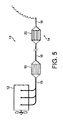
車両のポジティブ点火内燃機関12用排気システムにおいて、前記エンジンから排出された排気ガスの粒子性物質を濾過するためのフィルタ20を含み、前記フィルタは入口表面と出口表面を有する多孔性基材を含み、前記入口表面は第1平均細孔サイズを有する細孔を含む多孔性構造により前記出口表面と分離され、前記多孔性基材は多数の固体粒子を含む三元触媒ウォッシュコートでコーティングされ、前記ウォッシュコートでコーティングされた多孔性基材の前記多孔性構造は、第2平均細孔サイズを有し、前記第2平均細孔サイズは、前記第1平均細孔サイズよりも小さく、前記三元触媒ウォッシュコートは前記フィルタの上流に位置する分離基材モノリス18上に形成され、前記上流側基材モノリス上の前記三元触媒ウォッシュコートの質量は、前記三元触媒ウォッシュコートの質量全体の75%以下である排気システム10。 An exhaust system for a positive ignition internal combustion engine 12 of a vehicle includes a filter 20 for filtering particulate matter of exhaust gas exhausted from the engine, the filter including a porous substrate having an inlet surface and an outlet surface. The inlet surface is separated from the outlet surface by a porous structure comprising pores having a first average pore size, and the porous substrate is coated with a three-way catalyst washcoat comprising a number of solid particles; The porous structure of the porous substrate coated with a washcoat has a second average pore size, the second average pore size being smaller than the first average pore size, and the ternary A catalyst washcoat is formed on the separation substrate monolith 18 located upstream of the filter, and the three-way catalyst washcoat on the upstream substrate monolith. Bets mass, an exhaust system 10 wherein 75% or less of the total mass of the three-way catalyst washcoat.
Description
本発明は、車両ポジティブ点火内燃機関の排気ガス内の粒子性物質(PM)を処理するための排気システムに関し、特に理論空燃比で作動するが、リーン燃焼ポジティブ点火エンジンでも適切なPM処理用のフィルタを備える排気システムに関する。 The present invention relates to an exhaust system for treating particulate matter (PM) in the exhaust gas of a vehicle positive ignition internal combustion engine, particularly operating at a stoichiometric air-fuel ratio, but suitable for PM treatment even in a lean combustion positive ignition engine. The present invention relates to an exhaust system including a filter.
ポジティブ(電気)点火エンジンは、スパーク点火を利用して炭化水素と空気混合物を燃焼させる。反面、圧縮点火エンジンは炭化水素を圧縮空気に噴射することによって、炭化水素を燃焼させる。ポジティブ点火エンジンは、ガソリン燃料、メタノール及び/又はエタノールを含む酸素化物で混合されたガソリン燃料、LPG又はCNGを利用できる。 A positive (electric) ignition engine uses spark ignition to burn a hydrocarbon and air mixture. On the other hand, compression ignition engines burn hydrocarbons by injecting them into compressed air. A positive ignition engine may utilize gasoline fuel, gasoline fuel mixed with oxygenates including methanol and / or ethanol, LPG or CNG.
三元触媒(TWC)は、1つ以上の白金族金属、特に白金、パラジウム及びロジウムからなる群より選択されたことを一般的に含む。 A three-way catalyst (TWC) generally comprises one or more platinum group metals, particularly selected from the group consisting of platinum, palladium and rhodium.
三元触媒は、(i)一酸化炭素の二酸化炭素への酸化、(ii)燃焼されない炭化水素の二酸化炭素及び水への酸化、及び(iii)窒素酸化物の窒素及び酸素への還元、という3つの反応を同時に触媒作用を実行するものである。三元触媒は、リーン排気ガスからNOxを吸着するように設計されていない。反応(i)-(ii)はTWCが理論空燃比の近くで作動するエンジンから排出される排気ガスを収容するとき、最も効率的に発生する。本発明の技術分野でよく知られているように、ガソリン燃料がポジティブ点火(例えば、スパーク点火)内燃機関で燃焼される際に排出される一酸化炭素(CO)、燃焼されない炭化水素(HC)及び窒素酸化物(NOx)の量は、燃焼シリンダ内での空燃比により大部分影響を受ける。化学量論的に安定した組成を有する排気ガスは、酸化ガス(NOxとO2)と還元ガス(HCとCO)の濃度が実質的に一致する。化学量論的に安定した排気ガスの組成を生産する空燃比は、一般的に14.7:1で与えられる。 Three-way catalysts are (i) oxidation of carbon monoxide to carbon dioxide, (ii) oxidation of unburned hydrocarbons to carbon dioxide and water, and (iii) reduction of nitrogen oxides to nitrogen and oxygen. Three reactions are catalyzed simultaneously. Three-way catalyst is not designed to adsorb NO x from a lean exhaust gas. Reactions (i)-(ii) occur most efficiently when the TWC contains exhaust gas emitted from an engine operating near the stoichiometric air / fuel ratio. As is well known in the art of the present invention, carbon monoxide (CO), non-combusted hydrocarbons (HC) emitted when gasoline fuel is burned in a positive ignition (eg, spark ignition) internal combustion engine. And the amount of nitrogen oxides (NO x ) is largely influenced by the air-fuel ratio in the combustion cylinder. Exhaust gas having a stoichiometrically stable composition has substantially the same concentration of oxidizing gas (NO x and O 2 ) and reducing gas (HC and CO). The air / fuel ratio producing a stoichiometrically stable exhaust gas composition is generally given by 14.7: 1.
理論的には、化学量論的に安定した排気ガスの組成でO2、NOx、CO及びHCをCO2、H2O及びN2(及び残留O2)に完全に変換させることが可能でなければならず、これがTWCの役割である。従って、理想的にはエンジンがこのような方式で作動して燃焼混合物の空燃比が化学量論的に安定した排気ガスの組成を生産しなければならない。 Theoretically, O 2 , NO x , CO and HC can be completely converted to CO 2 , H 2 O and N 2 (and residual O 2 ) with a stoichiometrically stable exhaust gas composition. This must be the role of the TWC. Therefore, ideally, the engine must operate in this manner to produce an exhaust gas composition in which the air-fuel ratio of the combustion mixture is stoichiometrically stable.
排気ガスの酸化ガスと還元ガス間の組成的なバランスを定義する方法として、式(1)のように定義され得る排気ガスのラムダ(λ)値が挙げられる。
実際のエンジン空燃比/理論エンジン空燃比 (1)
ここで、1のラムダ値は化学量論的に安定した排気ガスの組成を示し、1より大きいラムダ値は過度なO2及びNOxを示し、組成は「リーン(lean)」と表現され、1より小さなラムダ値は過度なHCとCOを示し、組成は「リッチ(rich)」と表現される。一般的に空燃比によってエンジンが「理論空燃比」、「リーン」又は「リッチ」に作動し、空燃比に伴う排気ガスの組成により化学量論的に作動するガソリンエンジン又はリーン燃焼ガソリンエンジンがある。
As a method for defining the compositional balance between the oxidizing gas and the reducing gas of the exhaust gas, there can be mentioned the lambda (λ) value of the exhaust gas that can be defined as in the equation (1).
Actual engine air / fuel ratio / theoretical engine air / fuel ratio (1)
Here, a lambda value of 1 indicates a stoichiometrically stable exhaust gas composition, a lambda value greater than 1 indicates excessive O 2 and NO x , and the composition is expressed as “lean”; Lambda values less than 1 indicate excessive HC and CO, and the composition is expressed as “rich”. In general, there is a gasoline engine or a lean combustion gasoline engine in which the engine operates “stoichiometric air / fuel ratio”, “lean” or “rich” by the air / fuel ratio, and operates stoichiometrically by the composition of exhaust gas accompanying the air / fuel ratio. .
TWCを利用したNOxのN2への還元は、排気ガスの組成がリーンであるとき、効率が低下する。同様に、TWCは排気ガスの組成がリッチであるとき、COとHCを酸化させることができない。それにより、TWC内に入る排気ガスの組成をできるだけ化学量論な組成に維持させることが課題となっている。 The reduction of NO x to N 2 using TWC is less efficient when the exhaust gas composition is lean. Similarly, TWC cannot oxidize CO and HC when the exhaust gas composition is rich. Accordingly, it is a problem to maintain the composition of the exhaust gas entering the TWC as much as possible in the stoichiometric composition.
もちろん、エンジンが定常状態であるとき、空燃比を理論空燃比にすることは相対的に容易である。しかし、エンジンが車両を推進させるとき、要求される燃料の量はドライバによりエンジンに加えられる荷重の要求によって過渡的に(transiently)変わる。これは三元転換(3-way conversion)による化学量論的な排気ガスが発生するように空燃比を制御することを特に困難にさせる。実際に、空燃比は、排気ガス酸素(EGO)(又はラムダ)センサから排気ガスの組成に関する情報を受けるエンジン制御ユニットにより制御される:いわゆる閉ループフィードバックシステムという。このようなシステムの特徴は、空燃比が若干リッチな化学量論的(又は制御設定)地点と若干リーンな地点との間で振動することにあるが、これは空燃比の調節と関連した時間の遅延のためである。このような振動は、空燃比の振幅と反応周波数(Hz)により特徴付けられる。 Of course, when the engine is in a steady state, it is relatively easy to set the air-fuel ratio to the stoichiometric air-fuel ratio. However, when the engine propels the vehicle, the amount of fuel required varies transiently depending on the load demands applied to the engine by the driver. This makes it particularly difficult to control the air-fuel ratio so that stoichiometric exhaust gas is generated by 3-way conversion. In practice, the air / fuel ratio is controlled by an engine control unit that receives information about the composition of the exhaust gas from an exhaust gas oxygen (EGO) (or lambda) sensor: a so-called closed loop feedback system. A characteristic of such a system is that it oscillates between a stoichiometric (or control setting) point where the air / fuel ratio is slightly rich and a point where it is slightly lean, which is the time associated with the adjustment of the air / fuel ratio. Because of the delay. Such vibration is characterized by the air-fuel ratio amplitude and the response frequency (Hz).
一般的なTWCで活性成分は、高表面積の酸化物に支持された白金とロジウムと組み合わせられたパラジウム、又はパラジウム単独(ロジウムなし)のうちの1つ又は2つ、及び酸素貯蔵成分を含む。 Typical TWC active ingredients include one or two of palladium combined with platinum and rhodium supported on high surface area oxides, or palladium alone (no rhodium), and an oxygen storage component.
排気ガスの組成が設定ポイントに対して若干リッチであるとき、反応していないCOとHCを消費するための、即ち反応を更に化学量論的にさせるための少量の酸素が必要である。反対に、排気ガスが若干リーンであるときは、過度な酸素が消費される必要がある。これは振動時に酸素を放出又は吸収する酸素貯蔵成分の開発により達成された。TWCで最も一般的に用いられる酸素貯蔵成分(OSC)はセリウム酸化物(CeO2)又はCe/Zr混合酸化物のようなセリウムを含有する混合酸化物である。 When the exhaust gas composition is slightly rich with respect to the set point, a small amount of oxygen is required to consume unreacted CO and HC, ie to make the reaction more stoichiometric. Conversely, when the exhaust gas is slightly lean, excessive oxygen needs to be consumed. This has been achieved by the development of an oxygen storage component that releases or absorbs oxygen upon vibration. The oxygen storage component (OSC) most commonly used in TWC is a mixed oxide containing cerium, such as cerium oxide (CeO 2 ) or Ce / Zr mixed oxide.
一般的に、周辺のPMは空気動力学径(空気動力学径は、測定粒子と空気中で同一の沈降速度を有する1g/cm3密度である球形の直径として定義される)によって次のようなカテゴリーに分類される。
(i)PM-10-粒子:空気動力学径が10μm未満
(ii)微粒子:空気動力学径が2.5μm未満(PM-2.5)
(iii)超微粒子:空気動力学径が0.1μm(又は100nm)未満
(iv)ナノ粒子:空気動力学径が50nm未満
Generally, the surrounding PM is defined by the aerodynamic diameter (the aerodynamic diameter is defined as a spherical diameter that is 1 g / cm 3 density with the same settling velocity in the air as the measured particles): Into different categories.
(I) PM-10-particles: aerodynamic diameter less than 10 μm (ii) fine particles: aerodynamic diameter less than 2.5 μm (PM-2.5)
(Iii) Ultrafine particles: Aerodynamic diameter is less than 0.1 μm (or 100 nm) (iv) Nanoparticles: Aerodynamic diameter is less than 50 nm
1990年代半ば以降、微粒子と超微粒子が健康に及ぼし得る悪影響により、内燃機関から排出された粒子に対する粒子サイズの分類が大きく注目を集めている。周辺空気でPM-10粒子の濃度は、米国で法律的に規制される。PM-2.5に対する新しく、追加的な周辺空気の質標準が、人の死亡と2.5μm未満の微粒子の濃度間において強い相互関係にあるという研究結果が1997年に米国で紹介された。 Since the mid-1990s, particle size classification for particles discharged from internal combustion engines has attracted considerable attention due to the adverse effects that fine particles and ultrafine particles can have on health. The concentration of PM-10 particles in the ambient air is legally regulated in the United States. Research results were introduced in the United States in 1997 that a new and additional ambient air quality standard for PM-2.5 has a strong correlation between human death and microparticle concentrations below 2.5 μm.
現在は関心がディーゼル及びガソリンエンジンから発生するナノ粒子に移りつつあるが、これはナノ粒子がより大きいサイズの粒子よりも人の肺に、更に深く侵入することが知られており、2.5〜10.0μm範囲の粒子に関する研究結果に対する推定から結果として、より大きい粒子よりも更に危険であると認識される。 At present, interest is shifting to nanoparticles generated from diesel and gasoline engines, which are known to penetrate deeper into the human lung than particles of larger size, and 2.5. As a result from the estimates for the study results on particles in the range of -1.0 μm, it is recognized that they are even more dangerous than larger particles.
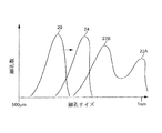
ディーゼル粒子の大きさの分布は、粒子核形成(nucleation)と密集化メカニズムに対応する明確に確立した双峰(bimodal)の特徴を有するが、対応する粒子の形態がそれぞれ原子核(nuclei)モードと蓄積モードを有する(図1参照)。図1から分かるように、原子核モードで、ディーゼルPMは非常に小さな質量を有する多数の小さな粒子からなる。殆ど全てのディーゼル粒子は1μmよりも遥かに小さな大きさを有するが、即ち1997にUS法律に含まれる微粒子、超微粒子及びナノ粒子の混合物を含む。 Diesel particle size distribution has well-established bimodal features corresponding to particle nucleation and compaction mechanisms, but the corresponding particle morphology is in nuclei mode and respectively. It has an accumulation mode (see FIG. 1). As can be seen from FIG. 1, in the nuclear mode, diesel PM consists of a large number of small particles with a very small mass. Almost all diesel particles have a size much smaller than 1 μm, ie they contain a mixture of microparticles, ultrafine particles and nanoparticles which are included in US law in 1997.
原子核モードの粒子は、大半が揮発性凝縮物(炭化水素、硫酸、硝酸など)からなり、粉塵と炭素のような小さな固形物質を含む。蓄積モードの粒子は凝縮物と混合された固体(炭素、金属性粉塵など)と吸着された物質(中質炭化水素)、硫黄種(sulfur species)、窒素酸化物派生物(nitrogen oxide derivatives)など)を含むことが理解される。コース(coarse)モードの粒子は、ディーゼルの燃焼過程で発生するものでないことが判断され、エンジンシリンダウォール、排気システム又は粒子サンプリングシステムからの粒子物質の堆積と後の再飛散(re-entrainment)のようなメカニズムを通じて形成され得る。これらのモード間の関係が図1に示されている。 Nuclear mode particles consist mostly of volatile condensates (hydrocarbons, sulfuric acid, nitric acid, etc.) and contain small solid substances such as dust and carbon. Accumulation mode particles include solids mixed with condensate (carbon, metallic dust, etc.), adsorbed substances (medium hydrocarbons), sulfur species, nitrogen oxide derivatives, etc. ). It is determined that coarse mode particles are not generated during the diesel combustion process, and the deposition and subsequent re-entrainment of particulate matter from engine cylinder walls, exhaust systems or particle sampling systems. It can be formed through such a mechanism. The relationship between these modes is shown in FIG.
核形成粒子の組成は、エンジンの作動条件、環境的な条件(特に、温度及び湿度)、希釈(dilution)及びサンプリングシステムの条件によって変わり得る。実験と理論は、原子核モードの形成と成長の大部分が低希釈比(low dilution ratio)の範囲で発生するということを示す。この範囲で、中質炭化水素と硫酸のような揮発性粒子前駆体のガスに対する粒子の変換は原子核モードでの同時発生的な核形成及び成長と蓄積モードでの存在粒子上への吸着に繋がる。実験室テスト(例えば、SAE980525及びSAE2001-01-0201参照)は、原子核モードの形成が空気希釈温度を減少させながら、強く増加するが、湿気が影響を及ぼすかに対する矛盾した証拠があることを示す。 The composition of the nucleating particles can vary depending on engine operating conditions, environmental conditions (particularly temperature and humidity), dilution and sampling system conditions. Experiments and theory show that the majority of nuclear mode formation and growth occurs in the range of low dilution ratios. In this range, conversion of particles to gases of volatile particle precursors such as medium hydrocarbons and sulfuric acid leads to simultaneous nucleation in nuclear mode and adsorption onto existing particles in growth and accumulation modes. . Laboratory tests (see, eg, SAE 980525 and SAE 2001-01-0201) show that the formation of nuclear modes increases strongly while decreasing the air dilution temperature, but there is conflicting evidence for the effect of moisture. .
一般に、低温、低希釈比、高湿度及び長い滞留時間は、ナノ粒子の形成と成長に影響を与える。研究によれば、非常に高い含有量で唯一の固相率の証拠として、ナノ粒子は中質炭化水素と硫酸のような揮発性物質からなる。 In general, low temperatures, low dilution ratios, high humidity, and long residence times affect nanoparticle formation and growth. Studies have shown that nanoparticles consist of volatile substances such as medium hydrocarbons and sulfuric acid, as evidence of the only solid fraction at very high contents.
対照的に、正常状態(steady state)動作でガソリン粒子のエンジン-アウト大きさの分布は、約60〜80nmのピークを有する単峰(unimodal)の分布を示す(SAE1999-01-3530の図4参照)。ディーゼル大きさの分布と比較すると、ガソリンPMは大部分無視する程度の蓄積とコースモードを有する超微粒子である。 In contrast, the engine-out size distribution of gasoline particles in steady state operation shows a unimodal distribution with a peak of about 60-80 nm (FIG. 4 of SAE 1999-01-3530). reference). Compared to the diesel size distribution, gasoline PM is an ultrafine particle with a negligible accumulation and course mode.
ディーゼル粒子フィルタでディーゼル粒子の粒子捕集は、多孔性障ウォールを利用して気相から気体に伝達された粒子を分離する原理に基づく。ディーゼルフィルタは、深層床濾過(deep−bed filter)及び/又は表面型フィルタ(surface-type filter)で定義され得る。深層濾過において、濾過材の平均細孔(pore:気孔、孔隙、間隙)サイズは、捕集された粒子の平均直径よりも大きい。粒子は、拡散堆積(ブラウン運動)、慣性堆積(インパクション)、流動-ライン遮断(ブラウン運動又は慣性)を含む深層濾過メカニズムの組み合わせを経て濾過材上に堆積される。 Particle collection of diesel particles with a diesel particle filter is based on the principle of separating particles transferred from the gas phase to the gas using a porous barrier. A diesel filter may be defined by a deep-bed filter and / or a surface-type filter. In the depth filtration, the average pore size (pore: pore, pore, gap) of the filter medium is larger than the average diameter of the collected particles. The particles are deposited on the filter media through a combination of depth filtration mechanisms including diffusion deposition (Brownian motion), inertial deposition (impact), and flow-line blockage (Brownian motion or inertia).
表面型フィルタでは、濾過材の細孔直径がPMの直径よりも小さいため、PMはふるい分け(sieving)により分離される。分離は、捕集されたディーゼルPM自体のビルドアップ(buil-up)により完了し、ビルドアップは一般的に「濾過ケーキ(filtration cake)」と呼ばれ、その過程は「ケーキ濾過」と呼ばれる。 In the surface type filter, since the pore diameter of the filter medium is smaller than the diameter of PM, PM is separated by sieving. Separation is completed by build-up of the collected diesel PM itself, which is generally referred to as “filtration cake” and the process is referred to as “cake filtration”.
セラミックウォールフローモノリスのようなディーゼル粒子フィルタは、深層又は表面濾過の組み合わせを通じて作用するものと考えられているが、濾過ケーキは深層濾過容量が飽和し、粒子層が濾過表面を覆い始めるとき、高いスート(soot:煤)荷重で成長する。深層濾過は、ケーキ濾過に比べて若干低い濾過効率と低い圧力低下の特徴を有する。 Diesel particle filters such as ceramic wall flow monoliths are thought to work through a combination of depth or surface filtration, but the filter cake is high when the depth filtration capacity is saturated and the particle layer begins to cover the filtration surface Grows with soot load. Depth filtration has the characteristics of slightly lower filtration efficiency and lower pressure drop than cake filtration.
WO03/011437は、排気ガスからPMを捕獲するための手段と排気ガス内の二酸化炭素及び/又は水分によるPMの酸化を促進させる触媒を含む排気システムを備えるガソリンエンジンを開示しており、触媒は支持されたアルカリ金属を含む。PM捕獲手段は10〜100nm範囲の粒子のPMを捕獲するのに適切であり、触媒でコーティングされたコーディエライトのような適切な細孔サイズのセラミック物質で製造されたウォールフローフィルタ、触媒を支持する金属酸化物フォーム、ワイヤーメッシュ、ディーゼル用に設計されたディーゼルウォールフローフィルタ、電気泳動(electrophoretic)トラップ又はサーモフォレティック(thermophoretic)トラップ(GB-A-2350804)であり得る。 WO 03/011437 discloses a gasoline engine comprising an exhaust system comprising means for capturing PM from exhaust gas and a catalyst that promotes oxidation of PM by carbon dioxide and / or moisture in the exhaust gas, Contains a supported alkali metal. The PM trapping means is suitable for capturing PM of particles in the 10-100 nm range, and a wall flow filter made of a ceramic material of appropriate pore size, such as cordierite coated with a catalyst, a catalyst. It can be a supporting metal oxide foam, a wire mesh, a diesel wall flow filter designed for diesel, an electrophoretic trap or a thermophoretic trap (GB-A-2350804).
WO2003/136232 A1は、多孔性セルウォール基礎物質からなるセルウォールを有するハニカムフィルタを含み、流入側にのみ又は流入及び流出側に表面層が備えられ、以下の(1)〜(5)の条件を満たすディーゼル粒子フィルタを開示している。(1)表面層の最大細孔径がセルウォール基礎物質の平均細孔径以下であり、表面層の細孔率はセルウォール基礎物質よりも大きい。(2)表面層に対して、最大細孔径は0.3〜20μmであり、細孔率は60〜95%である(水銀圧入法(mercury penetration method)を利用して測定)(3)表面層の厚さL1はセルウォール厚さL2の0.5〜30%である。(4)濾過面積当たりの表面層の質量は0.01〜6mg/cm2である。(5)セルウォール基礎物質に対して、平均細孔直径は10〜60μmであり、細孔率は40〜65%である。SAE論文番号2009-01-0292参照。 WO2003 / 136232 A1 includes a honeycomb filter having a cell wall made of a porous cell wall base material, and is provided with a surface layer only on the inflow side or on the inflow and outflow side, and the following conditions (1) to (5) A diesel particulate filter that satisfies the requirements is disclosed. (1) The maximum pore size of the surface layer is equal to or less than the average pore size of the cell wall basic material, and the porosity of the surface layer is larger than that of the cell wall basic material. (2) With respect to the surface layer, the maximum pore diameter is 0.3 to 20 μm and the porosity is 60 to 95% (measured using a mercury penetration method) (3) Surface The layer thickness L1 is 0.5-30% of the cell wall thickness L2. (4) The mass of the surface layer per filtration area is 0.01 to 6 mg / cm 2 . (5) With respect to the cell wall base material, the average pore diameter is 10 to 60 μm, and the porosity is 40 to 65%. See SAE article number 2009-01-0292.
気相からガソリンPMを分離するために、本技術分野で提案される他の技術はボルテックスリカバリを含む。 Other techniques proposed in the art for separating gasoline PM from the gas phase include vortex recovery.
2014年9月1日から適用される欧州の排気ガス法律(ユーロ6)は、ディーゼル及びガソリン(ポジティブ点火)乗用車の何れもから排出される粒子の数を規制する。ガソリンEUライトデューティー自動車(light duty vehicle)の場合、許容限界は次の通りである。一酸化炭素は1000mg/km、窒素酸化物(NOx)は60mg/km、全体炭化水素は100mg/km(このうち、非メタン炭化水素は68mg/km以下)、粒子性物質((PM)直接噴射エンジンの場合にのみ)は4.5mg/km。たとえ、当局はユーロ6に対するPM数の基準をまだ設定していなくても、1km当たりに6.0×1011に設定されることが一般的に考えられている。本明細書は、この数字が適切な時に採択されるという仮定に基づく。 The European exhaust gas law (Euro 6), applicable from 1 September 2014, regulates the number of particles emitted from both diesel and gasoline (positive ignition) passenger cars. In the case of a gasoline EU light duty vehicle, the tolerance limits are as follows. Carbon monoxide is 1000 mg / km, nitrogen oxide (NO x ) is 60 mg / km, total hydrocarbon is 100 mg / km (of which non-methane hydrocarbon is 68 mg / km or less), particulate matter ((PM) directly 4.5 mg / km only for injection engines). Even though the authorities have not yet set a PM number standard for Euro 6, it is generally considered to be set to 6.0 × 10 11 per km. This specification is based on the assumption that this number is adopted when appropriate.
米国では、まだ類似する排気ガスの基準が定められていない。しかし、カリフォルニア大気資源委員会(CARB:California Air Resource Board)は、最近「予備論議論文‐基準汚染源に対するカリフォルニア低公害車両(LEV:Low-Emission Vehicle)法規の修正−LEVIII」(2010年2月8日発表)というタイトルの論文を発表したが、ここには2〜4mg PM/mile(1.25-2.50mg PM/km(現在は10mg PM/mile(6.25mg PM/km))の新しいPM基準が提案され、「スタッフは粒子フィルタを使用せず、ガソリン直接噴射エンジンに対して3mg PM/mile(1.88mg PM/km)の基準が満たされ得るという提案を多数の製造会社から受けた」と記載されている。また、この論文はPM質量と排気ガスの数は互いに関連するものと見られるので、「たとえ、義務的な数字基準がここで考慮されていなくても、約1012粒子/mile[6.2511粒子/km]の選択的なPM数の基準が考慮され得る(これはPM質量基準の代りに製造会社により選択され得る)」と記載している。しかし、PM基準もPM数の基準もCARBによりまだ設定されていないため、カリフォルニア自動車市場又は米国自動車市場で一般的に粒子の濾過が必要であるか否かが分かることはまだ早い。それにも拘わらず、ある製造会社は最終的にいかなる基準が設定されても、その基準を満足させるために選択されたいかなるポジティブ点火エンジンの設計選択に対しても、安全余裕を提供するためのフィルタを選択するはずである。 In the United States, there are still no similar exhaust gas standards. However, the California Air Resources Board (CARB) recently announced that a preliminary discussion-"A Low-Emission Vehicle Regulation (LEV) Regulation for Reference Pollutants-LEVIII" (February 8, 2010). A new paper titled 2-4 mg PM / mile (1.25-2.50 mg PM / km (currently 10 mg PM / mile (6.25 mg PM / km))) PM standards were proposed, “Staff did not use particle filters and received a proposal from a number of manufacturers that the standard of 3 mg PM / mile (1.88 mg PM / km) could be met for gasoline direct injection engines. In addition, this paper describes the PM mass and Since the number of exhaust gases seems to be related to each other, “selective of about 10 12 particles / mile [6.25 11 particles / km], even if the mandatory numerical criteria are not considered here. , Which can be considered by the manufacturer instead of the PM mass standard. ”However, neither PM nor PM number standards have yet been set by CARB. However, it is still early to know whether particle filtration is generally required in the California automotive market or the US automotive market. For any positive ignition engine design choice chosen to meet the criteria, a filter should be selected to provide a safety margin.
新しいユーロ6排気ガスの基準は、ガソリン排気ガスの基準を満足させるために解決しなければならない様々な設計上の問題を提供する。特に、EUドライブサイクルで最大のオン(on)-サイクル背圧により測定されたのと同じ許容可能な背圧で何れもガソリン(ポジティブ点火)排気ガスのPM数を低減しながら、同時に窒素酸化物(NOx)、一酸化炭素(CO)及び燃焼していない炭化水素(HC)の1つ以上のような非PM汚染物質に対する排気ガスの標準を満足させるためのフィルタ又はフィルタを含む排気システムを設計する方法である。 The new Euro 6 exhaust standard provides various design issues that must be solved to meet the gasoline exhaust standard. In particular, at the same acceptable back pressure as measured by the maximum on-cycle back pressure in the EU drive cycle, both reduce the PM number of gasoline (positive ignition) exhaust gas while simultaneously reducing nitrogen oxides. An exhaust system comprising a filter or a filter to meet exhaust gas standards for non-PM pollutants such as one or more of (NO x ), carbon monoxide (CO) and unburned hydrocarbons (HC) How to design.
ユーロ6PM数の基準を満足させる三元触媒粒子フィルタに対する最小粒子の減少は、等価の流動触媒に対して50%以上である。追加的に、三元触媒ウォールフローフィルタの等価の流動触媒に対する若干の背圧の増加が必然的であるが、経験的に大部分の乗用車でMVEG-Bドライブサイクルに対する最大の背圧(「フレッシュ」から3回のテストに対する平均)は、180mbar未満又は150mbar未満のような200mbar未満、好ましくは120mbar未満(例えば、100mbar未満)に制限されなければならない。 The minimum particle reduction for a three-way catalyst particle filter that meets the Euro 6PM number criterion is over 50% for an equivalent flow catalyst. In addition, a slight increase in back pressure relative to the equivalent flow catalyst of the three-way catalyst wall flow filter is inevitably necessary, but empirically most passenger cars have a maximum back pressure for the MVEG-B drive cycle ("fresh" "Average over three tests" should be limited to less than 200 mbar, preferably less than 120 mbar, such as less than 180 mbar or less than 150 mbar (eg less than 100 mbar).
前述したように、ポジティブ点火エンジンにより発生したPMは、非常に高い比率の超微粒子を有し、ディーゼル(圧縮点火)エンジンにより発生したものに比べて無視する程度の蓄積及びコースモードを有するが、これはポジティブ点火エンジン排気ガスからPMを除去して大気に排出されるのを防止しなければならないという課題を与える。特に、ポジティブ点火エンジンから発生する大部分のPMは、ディーゼルPMの大きさ分布に比べて相対的に小さいため、ポジティブ点火PM表面型ケーキ濾過を促進するフィルタを使用することは実質的に不可能であるが、これはフィルタ基材の相対的に小さな平均細孔サイズがシステムであまりにも高い背圧を発生させるおそれがあるためである。 As mentioned above, PM generated by a positive ignition engine has a very high proportion of ultrafine particles and has negligible accumulation and course mode compared to that generated by a diesel (compression ignition) engine, This presents the problem that PM must be removed from the positive ignition engine exhaust gas and prevented from being discharged into the atmosphere. In particular, the majority of PM generated from positive ignition engines is relatively small compared to the size distribution of diesel PM, so it is virtually impossible to use a filter that promotes positive ignition PM surface cake filtration However, this is because the relatively small average pore size of the filter substrate can generate too high back pressure in the system.
また、ポジティブ点火エンジンから発生したPMの表面型濾過を促進させて関連する排気ガスの標準を満たすために、ディーゼルPM捕獲用に設計された従来のウォールフローフィルタを使用することは一般的に不可能であるが、これはポジティブ点火排気ガス内に一般的に、より少ないPMが存在し、スートケーキが少なく形成され、ポジティブ点火排気ガスの温度が一般的に更に高いため、酸化によるPMの迅速な除去に繋がり、ケーキ濾過による増加したPMの除去を妨げるためである。従来のディーゼルウォールフローフィルタでポジティブ点火PMの深層濾過も難しいが、これはPMがフィルタ濾過材の細孔サイズよりも非常に小さいためである。従って、正常作動で、コーティングされていない従来のディーゼルウォールフローフィルタは、ポジティブ点火エンジンと用いられるとき、圧縮点火エンジンよりも更に低いフィルタ効率を有する。 Also, it is generally not feasible to use a conventional wall flow filter designed for diesel PM capture to facilitate the surface-type filtration of PM generated from positive ignition engines to meet relevant exhaust gas standards. Although this is possible, this is generally due to the presence of less PM in the positive ignition exhaust gas, less soot cake formation, and generally higher temperatures of the positive ignition exhaust gas, thus allowing rapid oxidation of PM due to oxidation. This is to prevent the removal of increased PM by cake filtration. It is difficult to carry out depth filtration of positive ignition PM with a conventional diesel wall flow filter because PM is much smaller than the pore size of the filter medium. Thus, conventional, uncoated conventional diesel wall flow filters have a much lower filter efficiency than compression ignition engines when used with positive ignition engines.
他の困難は、許容可能な背圧で非PM汚染物質に対する排気ガスの標準を満たすための触媒のように、ウォッシュコート含有量と共に濾過効率を組み合わさせることである。近年、商業的に利用可能な車両でディーゼルウォールフロー粒子フィルタは、平均約13μmの細孔サイズを有する。しかし、発明者は必要なガソリン(ポジティブ点火)排気ガス基準を達成するために、US2006/0133969に記載されたように、十分な触媒含有量でこのような形態のフィルタをウォッシュコートすることは許容され得ない背圧を招くおそれがあることを見つけた。 Another difficulty is combining filtration efficiency with washcoat content, such as a catalyst to meet exhaust gas standards for non-PM pollutants with acceptable back pressure. In recent years, diesel wall flow particle filters in commercially available vehicles have an average pore size of about 13 μm. However, the inventor is allowed to washcoat such forms of filters with sufficient catalyst content as described in US 2006/0133969 to achieve the required gasoline (positive ignition) exhaust gas standards. I found that there was a risk of incurring back pressure that could not be done.
フィルタ背圧を低減するために、基材の長さを減少させることが可能である。しかし、フィルタの長さが減少することによって背圧は、制限された水準下で増加する。本発明に係るフィルタのための適切なフィルタ長さは2〜12インチ、好ましくは3〜6インチである。断面は原形であり得、本発明者の開発事業では4.66及び5.66インチの直径を有するフィルタを用いた。しかし、断面はフィルタの設置のために必要な車両の空間に左右される。従って、いわゆる隣接結合位置(例えば、エンジン排気マニホールド50cm以内)に位置するフィルタに対して楕円形又は卵形の断面空間を有し得る。予想するには、背圧もウォッシュコート含有量及びスート含有量と共に増加する。 In order to reduce the filter back pressure, it is possible to reduce the length of the substrate. However, as the filter length decreases, the back pressure increases under a limited level. A suitable filter length for the filter according to the invention is 2 to 12 inches, preferably 3 to 6 inches. The cross section may be intact and the inventors' development projects used filters with diameters of 4.66 and 5.66 inches. However, the cross section depends on the vehicle space required for the installation of the filter. Thus, it may have an elliptical or oval cross-sectional space for a filter located at a so-called adjacent coupling location (eg, within 50 cm of the engine exhaust manifold). As expected, back pressure also increases with washcoat content and soot content.
ユーロ6排気ガスの基準を満足させるために、近年、TWCをフィルタと結合させるための多くの努力が続けられてきた。 In recent years, many efforts have been made to combine TWCs with filters in order to meet Euro 6 exhaust emission standards.
US2009/0193796は、炭化水素、一酸化炭素、窒素酸化物及び粒子を処理するために、ガソリン直接噴射エンジンの下流に位置する排気ガス処理システムを開示しているが、この排気ガス処理システムは、粒子トラップ上にコーティングされるか、その内部に形成された三元触媒(TWC)を備える触媒粒子トラップを含む。説明によれば、TWCコーティング粒子トラップは、第1TWC触媒の下流側に位置し得、第1TWC触媒は粒子トラップ上にコーティングされたTWCの機能により要求されるものよりも小さくなり得る。第1TWCと下流のTWCコーティング粒子トラップを何れも備える排気システムの具体的な例は記載されていない。 US 2009/0193796 discloses an exhaust gas treatment system located downstream of a gasoline direct injection engine to treat hydrocarbons, carbon monoxide, nitrogen oxides and particles, A catalyst particle trap comprising a three way catalyst (TWC) coated on or formed within the particle trap is included. According to the description, the TWC coated particle trap can be located downstream of the first TWC catalyst, and the first TWC catalyst can be smaller than required by the function of the TWC coated on the particle trap. No specific example of an exhaust system comprising both a first TWC and a downstream TWC coated particle trap is described.
WO2009/043390は、フィルタ成分と2層からなる触媒作用で活性であるコーティングを含む触媒作用で活性である粒子フィルタを開示する。第1層は流入排気ガスと接触し、第2層は流出排気ガスと接触する。2層とも酸化アルミニウムを含む。第1層はパラジウムを含み、第2層はロジウムに追加された酸素-貯蔵混合セリウム/ジルコニウム酸化物を含む。例えば、不特定の平均細孔サイズのウォールフローフィルタ基材は、約31g/lの含有量で第1層にコーティングされ、約30g/lの含有量で第2層にコーティングされる。即ち、ウォッシュコート含有量は、約1.00g in-3である。大部分の車両分野で、このようなコーティングフィルタだけでは必要な排気ガス基準を満足させることができないと判断される。明細書は、触媒作用で活性である粒子フィルタを含む主に理論空燃比の混合気で作動する燃焼機関の排気ガスの浄化用排気ガス制御システムを開示している。WO‘390には排気ガス制御システムが流動-貫通基材モノリス上に配置され、触媒作用で活性である粒子フィルタの上流側に位置する分離されたTWCと組み合わせられて使用され得るということに関するいかなる提案や暗示もない。 WO 2009/043390 discloses a catalytically active particle filter comprising a filter component and a catalytically active coating consisting of two layers. The first layer contacts the inflowing exhaust gas, and the second layer contacts the outflowing exhaust gas. Both layers contain aluminum oxide. The first layer contains palladium and the second layer contains oxygen-storage mixed cerium / zirconium oxide added to rhodium. For example, an unspecified average pore size wall flow filter substrate is coated on the first layer with a content of about 31 g / l and coated on the second layer with a content of about 30 g / l. That is, the washcoat content is about 1.00 g in -3 . In most vehicle fields, it is determined that such a coating filter alone cannot meet the required exhaust gas standards. The specification discloses an exhaust gas control system for the purification of exhaust gas of a combustion engine operating mainly with a stoichiometric air / fuel mixture comprising a catalytically active particle filter. WO'390 describes any that an exhaust gas control system can be used in combination with a separate TWC located on the flow-through substrate monolith and located upstream of the catalytically active particle filter. There are no suggestions or suggestions.
GB2468210は、ポジティブ点火エンジンから排出された排気ガスから粒子性物質(PM)を濾過するためのフィルタを開示しており、このフィルタは入口表面と出口表面を有する多孔性基材を含み、前記入口表面は第1平均細孔サイズの細孔を有する多孔性構造により前記出口表面と分離され、前記多孔性基材は多数の固体粒子を含むウォッシュコートでコーティングされ、前記ウォッシュコートされた多孔性基材の前記多孔性構造は第2平均細孔サイズの細孔を有し、前記第2平均細孔サイズは前記第1平均細孔サイズよりも小さい。実施形態において、前記ウォッシュコートは触媒作用し、特定の実施形態における前記触媒はTWCである。 GB 2468210 discloses a filter for filtering particulate matter (PM) from exhaust gas exhausted from a positive ignition engine, the filter comprising a porous substrate having an inlet surface and an outlet surface, wherein the inlet The surface is separated from the outlet surface by a porous structure having pores of a first average pore size, the porous substrate is coated with a washcoat containing a number of solid particles, and the washcoated porous group The porous structure of the material has pores having a second average pore size, and the second average pore size is smaller than the first average pore size. In embodiments, the washcoat is catalyzed and in certain embodiments, the catalyst is TWC.
ポジティブ点火内燃機関からの粒子性物質を濾過するためのフィルタに対する実質的な困難は、乗用車における空間が制限され得、フィルタが車両の下部に吊られているクーラ内に位置(いわゆる、「アンダフロア」位置)しなければならないこともあり得るということである。しばしば、フィルタをエンジンマニホールドに近接した(いわゆる「近接-結合」位置)高温の位置に位置させる空間が車両に十分ではなく、とにかく相対的に高いフィルタの熱質量は触媒がエンジンコールド-スタートに次いで、十分に速く「ライトオフ」されるのを防ぐ。これは、定められたドライブサイクルにかけて法律が車両排気ガスを評価することであるため、重要である。大部分のポジティブ点火エンジン車両の汚染性排気ガスは、コールド-スタートに次いで、最初の数秒内にテストサイクルで発生する。万が一、TWCがコールド-スタートに次いで、十分に速く活性されなければ、これは全体的にドライブサイクルにかけて関連した排気ガス標準の通過と失敗間の差を招くおそれがある。 The substantial difficulty with a filter for filtering particulate matter from a positive ignition internal combustion engine is that the space in the passenger car can be limited and the filter is located in a cooler suspended at the bottom of the vehicle (so-called “underfloor”). "Position" may have to be. Often, there is not enough room in the vehicle to place the filter close to the engine manifold (so-called “proximity-coupled” position), and the thermal mass of the filter is relatively high following the engine cold-start. Prevent being "lighted off" fast enough. This is important because the law is to evaluate vehicle exhaust over a defined drive cycle. Most positive ignition engine vehicle polluting exhaust gases are generated in a test cycle within the first few seconds following a cold start. In the unlikely event that the TWC is not activated fast enough following a cold start, this can lead to a difference between the passing and failure of the associated exhaust gas standard throughout the drive cycle.
「ライト-オフ」は、触媒が好ましい転換活性で反応を促進させる温度として定義され得る。例えば、「CO T50」は特定の触媒が少なくても50%の効率で供給ガス内の一酸化炭素をCO2のようなガスに変換させる温度である。同様に、「HC T80」はオクタン又はプロパンのような炭化水素が少なくても80%の効率で、例えば水蒸気やCO2に変換させる温度である。 “Light-off” can be defined as the temperature at which the catalyst promotes the reaction with the preferred conversion activity. For example, “CO T 50 ” is the temperature at which carbon monoxide in the feed gas is converted to a gas such as CO 2 with an efficiency of at least 50% for a specific catalyst. Similarly, “HC T 80 ” is the temperature at which hydrocarbons such as octane or propane are converted to, for example, water vapor or CO 2 with an efficiency of at least 80%.
従って、実際に現在販売されている車両ポジティブ点火エンジン用排気システムは、近接結合位置に位置する流動-貫通モノリス基材を含む相対的に低い熱質量TWCを備える。 Accordingly, the exhaust systems for vehicle positive ignition engines that are currently sold in practice are equipped with a relatively low thermal mass TWC that includes a flow-through monolith substrate located in the close coupling position.
しかし、本発明の発明者らは、TWCで触媒作用するフィルタが車両のアンダフロアと商業的に利用可能な近接-結合された(流動-貫通)TWCの下流側に位置するとき、フィルタの温度はテストサイクル又は実際のドライブ条件で粒子性物質を燃焼させることは明確に不十分である。初期にはポジティブ点火PMが酸素でディーゼルPMよりも低い温度で燃焼されると提案された。しかし、本発明の発明者らは、ポジティブ点火エンジンからの粒子性物質を燃焼させるために、500℃を超えるフィルタ温度が必要であるということを見つけた。フィルタの温度を増加させたり、電気的に加熱されたフィルタの触媒のような他の手段を用いるために、シリンダ内の燃料噴射器のエンジン制御部を通るか、排気ガス内に直接炭化水素を排気ガス内に間欠的に追加で噴射することが可能である。しかし、このような方法は費用が多くかかり、技術的に複雑であり、窮極的に燃料消費を増加させるため、ドライバには不利益に作用する。 However, the inventors of the present invention have found that when the TWC-catalyzed filter is located downstream of the vehicle underfloor, a commercially available proximity-coupled (flow-through) TWC, the temperature of the filter Is clearly inadequate to burn particulate matter in test cycles or actual drive conditions. Initially it was proposed that positive ignition PM would be burned with oxygen at a lower temperature than diesel PM. However, the inventors of the present invention have found that filter temperatures in excess of 500 ° C. are required to burn particulate matter from positive ignition engines. In order to increase the temperature of the filter or to use other means such as electrically heated filter catalyst, the engine control part of the fuel injector in the cylinder or the hydrocarbons directly into the exhaust gas It is possible to inject additionally into the exhaust gas intermittently. However, such a method is costly, technically complex, and significantly increases fuel consumption, which is detrimental to the driver.
これから、本発明の発明者らは驚いたことにも、フィルタ温度を増加させるために炭化水素を追加的に噴射させるのと同様の方式でフィルタ温度が法律で定められたドライブサイクルの少なくとも一部区間に粒子性物質を被動的に燃焼させたり、少なくとも活動的な介入周期を非常に低減させるのに十分な温度を維持する車両ポジティブ点火内燃機関用排気システムを設計することが可能であるということを見つけた。 From this, the inventors of the present invention were surprisingly surprised at least in part of the drive cycle where the filter temperature was stipulated by law in the same manner as injecting additional hydrocarbons to increase the filter temperature. It is possible to design an exhaust system for a vehicle positive ignition internal combustion engine that passively burns particulate matter in the section, or at least maintains a temperature sufficient to greatly reduce the active intervention period I found
一側面によれば、本発明は、車両ポジティブ点火内燃機関用排気システムを提供するが、前記システムは、前記内燃機関から排出された排気ガスの粒子性物質を濾過するためのフィルタを含み、前記フィルタは入口表面と出口表面を有する多孔性基材を含み、前記入口表面は第1平均細孔サイズの細孔を有する多孔性構造により前記出口表面と分離され、前記多孔性基材は多数の固体粒子を含む三元触媒ウォッシュコートでコーティングされ、前記ウォッシュコートされた多孔性基材の前記多孔性構造は第2平均細孔サイズを含み、前記第2平均細孔サイズは前記第1平均細孔サイズよりも小さく、三元触媒ウォッシュコートが前記フィルタの上流側に分離された基材モノリス上に配置され、前記上流側基材モノリス上の三元触媒ウォッシュコートの質量は、前記システムで三元触媒ウォッシュコートの質量全体の75%以下である。 According to one aspect, the present invention provides an exhaust system for a vehicle positive ignition internal combustion engine, the system including a filter for filtering particulate matter of exhaust gas exhausted from the internal combustion engine, The filter includes a porous substrate having an inlet surface and an outlet surface, the inlet surface being separated from the outlet surface by a porous structure having pores of a first average pore size, the porous substrate having a number of porous substrates. Coated with a three-way catalyst washcoat comprising solid particles, the porous structure of the washcoated porous substrate includes a second average pore size, and the second average pore size is the first average fine size. A three-way catalyst washcoat on the upstream substrate monolith, wherein the three-way catalyst washcoat is smaller than the pore size and disposed on the substrate monolith separated upstream of the filter. Over bets mass is 75% or less of the total weight of the three-way catalyst washcoat in the system.
本発明が行える3つの方法は、第一に、車両スパーク点火エンジン用排気システムで上流基材モノリスとして一般的に用いられるものよりも更に小さな体積の基材を使用するが、一般的に用いられるウォッシュコートの含有量、即ち、単層又は多層構造として全体約3gin-3よりも大きいウォッシュコート含有量の同一のTWCを使用することを含む。現在、用いられる上流側基材モノリスはエンジン排気量の60〜100%であり、従ってエンジン排気量の60%未満(例えば、55%未満、50%未満又は45%未満)の約3gin-3よりも大きいウォッシュコートの含有量でコーティングされた基材モノリスは、本発明で適用される触媒作用された上流側基材モノリスの説明に役立つ実施例である。前記上流側基材モノリスが2つの部分(上流側部分と下流側部分)を含むことが可能であるが、各部分は他のウォッシュコート含有量、貴金属含有量及び/又は体積を有する。後者の2つの部分の概念も本発明の範囲に属する。 Three methods in which the present invention can be used are first commonly used, although a smaller volume of substrate is used than is commonly used as an upstream substrate monolith in an exhaust system for a vehicle spark ignition engine. Including the use of the same TWC with a washcoat content, i.e., a washcoat content greater than about 3 gin- 3 overall as a single layer or multilayer structure. Currently, the upstream substrate monolith used is 60-100% of engine displacement and is therefore less than about 3 gin- 3 , which is less than 60% of engine displacement (eg, less than 55%, less than 50% or less than 45%) A substrate monolith coated with a larger washcoat content is an illustrative example of the catalyzed upstream substrate monolith applied in the present invention. The upstream substrate monolith can include two parts (upstream part and downstream part), each part having another washcoat content, noble metal content and / or volume. The concept of the latter two parts also belongs to the scope of the present invention.
このような最初の配置において、前記上流側基材モノリスの軸方向の長さは、時々、この分野で「スライス」と呼ばれ、三元触媒フィルタ基材上に相対的に高いウォッシュコート含有量で組み合わせられた商業的に利用可能な近接-結合基材モノリスよりも短くなり得る。 In such an initial arrangement, the axial length of the upstream substrate monolith is sometimes referred to in the art as a “slice” and has a relatively high washcoat content on the three way catalyst filter substrate. Can be shorter than commercially available proximity-bonded substrate monoliths combined in
第二に、上流側基材モノリスは、車両スパーク点火エンジン用排気システムで一般的に用いられる上流側基材モノリスの大きさと同一であるか、類似し得る。即ち、エンジン排気量の60〜100%であるが、用いられたウォッシュコート含有量は一般的な上流側基材モノリスとして用いられるものよりも小さいため、単層又は多層構造で全体的に2.75gin-3未満、2.5gin-3未満又は2gin-3未満のような3gin-3未満である。 Second, the upstream substrate monolith may be the same as or similar to the size of the upstream substrate monolith commonly used in vehicle spark ignition engine exhaust systems. That is, it is 60 to 100% of the engine displacement, but the washcoat content used is smaller than that used as a general upstream substrate monolith, so that it is generally 2. 75gin less than -3, a 3gin less than -3, such as less than 2.5Gin -3 or less than 2Gin -3.
第三に、前記上流側基材モノリスとして用いるためのTWCは、車両スパーク点火エンジン用排気システムで使用するための一般的なものよりも本質的に不十分な活性のウォッシュコートであり得、より低い白金族金属含有量を有するか、2以上の白金族金属が用いられる場合、1つ以上の白金族金属の重量比は1つ以上の他の白金族金属に比べて更に低く、又はその組み合わせは更に低い酸素貯蔵活性度(例えば、セリウムとジルコニウムに基づく混合酸化物の低い含有量)を有し得る。 Third, the TWC for use as the upstream substrate monolith can be a substantially less active washcoat than is typical for use in an exhaust system for a vehicle spark ignition engine, and more When having a low platinum group metal content or when two or more platinum group metals are used, the weight ratio of one or more platinum group metals is even lower than one or more other platinum group metals, or combinations thereof Can have even lower oxygen storage activity (eg, low content of mixed oxides based on cerium and zirconium).
もちろん、前記3つの選択において2つ以上で若干の変更がなされることもあり得る。 Of course, there may be a slight change in two or more in the three selections.
実施形態において、前記上流側基材モノリス上のTWCウォッシュコートの質量は、システムでTWCウォッシュコート質量全体の70%以下(例えば、65%以下、60%以下又は55%以下)である。 In an embodiment, the mass of the TWC washcoat on the upstream substrate monolith is 70% or less (eg, 65% or less, 60% or less, or 55% or less) of the total TWC washcoat mass in the system.
本発明は、前記上流側TWCの効率性を若干低下させることによって、十分な汚染物質(CO、燃焼されていない炭化水素、NOxなど)が三元触媒フィルタと接触するように抜け出せないという発見に基づく。三元触媒フィルタで残っている汚染物質に対する触媒作用による転換はフィルタ温度を増加させる発熱を発生させ、フィルタで粒子性物質を燃焼させるのに十分にフィルタ温度を上昇させる。前記の論議から近接-結合TWCは、コールドスタート後にできるだけ、迅速、かつ、効率的に汚染物質を処理するように設計されるため、このような配置は、本技術分野において企業標準とは反直感的であることが明白である。このような原理の効果は、コンピュータモデリング(実施形態8参照)により実証され得る。 Discovery that the present invention is that by slightly reduce the efficiency of the upstream TWC, sufficient pollutants (CO, combustion that is not a hydrocarbon, such as NO x) does not escape into contact with the three-way catalytic filter based on. Catalytic conversion of contaminants remaining in the three-way catalyst filter generates heat that increases the filter temperature, raising the filter temperature sufficiently to burn particulate matter in the filter. From the above discussion, proximity-coupled TWCs are designed to treat contaminants as quickly and as efficiently as possible after a cold start, so such an arrangement is counterintuitive to corporate standards in the art. It is clear that The effect of such a principle can be demonstrated by computer modeling (see Embodiment 8).
本発明は、前記上流側基材モノリスを十分な反応ガスを通過させて下流に位置する三元触媒フィルタが一般的に製造された近接-結合TWCに対して、400℃のフィルタ入口ガス温度に対して、例えば50℃を超えるように増加するように設計されるものと定義されたように、機能的に定義されることもでき、前記上流側基材モノリスのTWCは75%未満、70%未満、65%未満又は60%未満のように80%未満で汚染物質転換するように設計される。前記の他の定義が何れも先行技術をより一層明示的に区別するために主張された定義を補完できることが理解できるだろう。 The present invention provides a filter inlet gas temperature of 400 ° C. with respect to a proximity-coupled TWC in which a three-way catalytic filter generally downstream of the upstream substrate monolith through which sufficient reaction gas is passed is manufactured. On the other hand, it can also be defined functionally, for example as defined to be designed to increase above 50 ° C., where the TWC of the upstream substrate monolith is less than 75%, 70% Designed to convert pollutants in less than 80%, such as less than 65% or less than 60%. It will be appreciated that any of the other definitions above can complement the definitions claimed to make the prior art more distinct.
前記フィルタの上流に位置する前記分離された基材モノリスは、好ましくは流動-貫通基材モノリス(例えば、セラミック又は金属構造からなる)である。しかし、流動-貫通モノリス以外の基材モノリスが部分フィルタ(例えば、WO01/080978又はEP1057519参照)のように、好ましい金属フォーム基材などとして使用され得る。 The separated substrate monolith located upstream of the filter is preferably a flow-through substrate monolith (eg, consisting of a ceramic or metal structure). However, substrate monoliths other than flow-through monoliths can be used as preferred metal foam substrates and the like, such as partial filters (see, for example, WO01 / 080978 or EP1057519).
前記上流側基材モノリス上のTWCウォッシュコートの質量は、システムでTWCウォッシュコートの質量全体に比例することが理解され得るだろう。これはフィルタに追加された2つ以上の基材モノリスは、TWCウォッシュコートを含む装置を利用するように意図される。しかし、好適な実施形態において、上流側基材モノリス上のTWCウォッシュコートの質量は、フィルタのTWCウォッシュコートと上流側基材モノリスの質量全体に比例すると定義される。 It can be seen that the mass of the TWC washcoat on the upstream substrate monolith is proportional to the overall mass of the TWC washcoat in the system. It is intended that two or more substrate monoliths added to the filter utilize a device that includes a TWC washcoat. However, in a preferred embodiment, the mass of the TWC washcoat on the upstream substrate monolith is defined to be proportional to the overall mass of the TWC washcoat and upstream substrate monolith of the filter.
本発明のこのような側面で使用するためのポジティブ点火エンジンは、ガソリン燃料、メタノール及び/又はエタノールを含む酸素化物と混合されたガソリン燃料、LPG又はCNGを使用できる。 A positive ignition engine for use in this aspect of the invention can use gasoline fuel, gasoline fuel mixed with oxygenates including methanol and / or ethanol, LPG or CNG.
初期に、本発明は、ポジティブ点火エンジン排気ガスの粒子数を30%(例えば、50%、80%、90%)以上、許容可能な背圧で低減できる。 Initially, the present invention can reduce the number of positive ignition engine exhaust gas particles by 30% (eg, 50%, 80%, 90%) or more with an acceptable back pressure.
平均細孔サイズは、水銀細孔率の測定により決定され得る。 The average pore size can be determined by measuring mercury porosity.
本発明で使用するためのフィルタは、実質的に基材の細孔率に独立的であるという長所を提供できる。細孔率は、多孔性基材において空き空間の割合であって、排気システムの背圧と関連するが、一般的に、細孔率が低いほど背圧は高くなる。しかし、本発明で使用するためのフィルタの細孔率は、一般的に40%又は50%を超え、50〜65%又は55〜60%のような45〜75%の細孔率が有利に使用され得る。前記ウォッシュコーティングされた多孔性基材の平均細孔サイズは、濾過のために重要である。従って、平均細孔サイズが大きいため、質の悪いフィルタである相対的に高い細孔率の多孔性基材を有し得る。 Filters for use in the present invention can provide the advantage of being substantially independent of the porosity of the substrate. The porosity is a ratio of empty space in the porous substrate and is related to the back pressure of the exhaust system. Generally, the lower the porosity, the higher the back pressure. However, the porosity of the filter for use in the present invention is generally greater than 40% or 50%, with a porosity of 45-75% such as 50-65% or 55-60% being advantageous. Can be used. The average pore size of the wash-coated porous substrate is important for filtration. Therefore, since the average pore size is large, it can have a porous substrate with a relatively high porosity, which is a poor quality filter.
前記多孔性基材は、焼結金属のような金属、又は炭化ケイ素、コーディエライト、窒化アルミニウム、窒化ケイ素、チタン酸アルミニウム(aluminium titanate)、アルミナ、ムライト(mullite)(例えば、針状の(acicular)ムライト(例えば、WO01/16050参照))、ポルサイトなどのようなセラミック、Al2O3/Fe、Al2O3/Ni又はB4C/Feのようなサーメット又はこれらのうち2つ以上の部分を含む複合材料であり得る。好適な実施形態において、前記フィルタは、多数の入口チャネルと多数の出口チャネルを有するセラミック多孔性フィルタを含むウォールフローフィルタであり、各入口チャネルと各出口チャネルは多孔性構造のセラミックウォールによる部分で定義され、入口チャネルのそれぞれは、多孔性構造のセラミックウォールにより出口チャネルと分離される。このようなフィルタの配置は、SAE810114にも開示されており、より詳細な説明のために、ここで参照され得る。これとは異なり、フィルタはフォーム又はEP1057519又はWO01/080978に開示されたのと同一の、いわゆる部分フィルタであり得る。 The porous substrate may be a metal such as sintered metal, or silicon carbide, cordierite, aluminum nitride, silicon nitride, aluminum titanate, alumina, mullite (eg, needle-shaped ( acicular) mullite (see, for example, WO 01/16050)), ceramics such as porcite, cermets such as Al 2 O 3 / Fe, Al 2 O 3 / Ni or B 4 C / Fe or two of these It may be a composite material including the above parts. In a preferred embodiment, the filter is a wall flow filter comprising a ceramic porous filter having a number of inlet channels and a number of outlet channels, each inlet channel and each outlet channel being a portion of a porous ceramic wall. As defined, each of the inlet channels is separated from the outlet channel by a porous structured ceramic wall. Such a filter arrangement is also disclosed in SAE810114, which may be referred to here for a more detailed description. Alternatively, the filter can be a foam or the same so-called partial filter as disclosed in EP 1057519 or WO 01/080978.
ディーゼルに適用するためのウォールフローフィルタをコーティングする目的は、本発明のそれと一般的に異なる。ディーゼルでは、ウォッシュコートが触媒成分を、NOをNO2に酸化させるための触媒のようなフィルタ基材に案内するために用いられるが、スートが蓄積されることによって背圧を避けなければならないという大きな問題がある。従って、好適な触媒活性度と許容可能な背圧との間でバランスが崩れる。対照的に、本発明で使用するための多孔性基材をウォッシュコーティングする主な目的は、好ましい濾過効率と触媒活性度を何れも達成するためである。 The purpose of coating wall flow filters for application to diesel is generally different from that of the present invention. That the diesel, the washcoat catalyst component is used to guide the filter substrate, such as a catalyst for the oxidation of NO to NO 2, must avoid back pressure by soot is accumulated There is a big problem. Thus, a balance is lost between suitable catalyst activity and acceptable back pressure. In contrast, the main purpose of washcoating a porous substrate for use in the present invention is to achieve both preferred filtration efficiency and catalyst activity.
一実施形態において、第1平均細孔サイズ(例えば、前記多孔性フィルタ基材の多孔性構造の表面細孔)は、8〜45μm(例えば、8〜25μm、10〜20μm又は10〜15μm)である。特定の実施形態において、第1平均細孔サイズは、18μmを超える(例えば、15〜45、20〜45μm、20〜30μm、25〜45μm)。 In one embodiment, the first average pore size (eg, surface pores of the porous structure of the porous filter substrate) is 8 to 45 μm (eg, 8 to 25 μm, 10 to 20 μm, or 10 to 15 μm). is there. In certain embodiments, the first average pore size is greater than 18 μm (eg, 15-45, 20-45 μm, 20-30 μm, 25-45 μm).
実施形態において、フィルタは0.5g in-3超過又は0.80g in-3以上(例えば、0.80〜3.00gin-3)のように0.25g in-3を超えるウォッシュコート含有量を有し得る。好適な実施形態において、前記ウォッシュコートの含有量は、1.2g in-3以上、1.5g in-3超過、1.6g in-3超過又は2.00g in-3超過又は例えば1.6〜2.4g in-3のように1.00g in-3を超えることができる。フィルタ平均細孔サイズとウォッシュコート含有量の特定の組み合わせにおいて、前記フィルタは許容可能な背圧で粒子濾過と触媒活性度の好ましい水準を組み合わせる。 In embodiments, the filter is 0.5 g in -3 overshooting or 0.80 g in -3 or more (e.g., 0.80~3.00gin -3) washcoat content of more than 0.25 g in -3 as Can have. In a preferred embodiment, the content of the washcoat is 1.2 g in −3 or more, 1.5 g in −3 in excess, 1.6 g in −3 in excess or 2.00 g in −3 in excess or, for example, 1.6 It can exceed 1.00 g in -3 , like ~ 2.4 g in -3 . In a particular combination of filter average pore size and washcoat content, the filter combines preferred levels of particle filtration and catalyst activity with acceptable back pressure.
第1の好適な実施形態において、前記フィルタは表面ウォッシュコートを含むが、ウォッシュコート層は多孔性構造の表面細孔を実質的に覆い、前記ウォッシュコーティングされた多孔性基材の細孔は、ウォッシュコート内の粒子間の空間(粒子間細孔)で部分的に定義される。即ち、実質的にウォッシュコートがないことは多孔性基材の多孔性構造に入らない。表面コーティングされた多孔性フィルタ基材を製造する方法は、ポリマー(例えば、ポリビニルアルコール(PVA))を前記多孔性構造内に案内する段階と、前記ポリマーを含む前記多孔性フィルタ基材にウォッシュコートを塗布する段階と、乾燥させる段階と、前記コーティングされた基材をか焼して前記ポリマーを燃焼させる段階とを含む。第1実施形態の概略的な構成が図2Aに示されている。 In a first preferred embodiment, the filter comprises a surface washcoat, wherein the washcoat layer substantially covers the surface pores of the porous structure, and the pores of the washcoated porous substrate are: It is defined in part by the space between particles (interparticle pores) in the washcoat. That is, substantially no washcoat does not enter the porous structure of the porous substrate. A method of manufacturing a surface-coated porous filter substrate includes the steps of guiding a polymer (eg, polyvinyl alcohol (PVA)) into the porous structure, and washcoating the porous filter substrate containing the polymer. Applying, drying, and calcining the coated substrate to burn the polymer. A schematic configuration of the first embodiment is shown in FIG. 2A.
多孔性フィルタ基材をコーティングする方法は当業者に知られており、WO99/47260に記載された方法(即ち、モノリシック支持体をコーティングする方法)を制限なしに含み、(a)支持体の上部に密閉手段を位置させる段階、(b)液体成分の予め決定された量を前記密閉手段内に注入する段階((a)の後(b)又は(b)の後(a))(c)圧力又は真空を加えて、前記液体成分を前記支持体の少なくとも一部分に引き込み、前記支持体内で前記全ての量を実質的に維持する段階とを含む。このような工程段階は、選択的な燃焼/か焼による前記第1コーティングの乾燥に次いで、前記モノリシック支持体の他の端部から繰り返され得る。 Methods for coating porous filter substrates are known to those skilled in the art and include, without limitation, the methods described in WO 99/47260 (ie, methods for coating monolithic supports), (a) the top of the support (B) or (b) or (b) (a) or (c) injecting a predetermined amount of liquid component into the sealing means. Applying pressure or vacuum to draw the liquid component into at least a portion of the support to substantially maintain the entire amount within the support. Such process steps can be repeated from the other end of the monolithic support following drying of the first coating by selective combustion / calcination.
このような第1実施形態において、前記多孔性ウォッシュコートの平均粒子間細孔サイズは、0.1〜1.0μmのような5.0nm〜5.0μmである。 In the first embodiment, the average interparticle pore size of the porous washcoat is 5.0 nm to 5.0 μm, such as 0.1 to 1.0 μm.
このような第1の表面コーティング実施形態において、固体ウォッシュコート粒子のD90は、前記多孔性フィルタ基材の平均細孔サイズよりも更に大きくなり得、15〜30μm又は12〜25μmのように10〜40μmの範囲であり得る。ここで用いられる「D90」は、粒子の90%が特定された範囲内の直径を有するウォッシュコート内で粒子サイズの分布を定義する。これとは異なり、各実施形態において、固体ウォッシュコート粒子の平均大きさは1〜20μmの範囲内にある。ウォッシュコート内で粒子サイズの範囲が広いほど、ウォッシュコートが多孔性基材の多孔性構造に入りやすくなり得る。従って、「実質的にウォッシュコートのないものは、多孔性基材の多孔性構造に入らない」ということは、それにより解釈されるべきである。 In such a first surface coating embodiment, the D90 of the solid washcoat particles can be larger than the average pore size of the porous filter substrate, such as 10-30, such as 15-30 μm or 12-25 μm. It can be in the range of 40 μm. As used herein, “D90” defines the particle size distribution within a washcoat where 90% of the particles have a diameter within a specified range. In contrast, in each embodiment, the average size of the solid washcoat particles is in the range of 1-20 μm. The wider the particle size range in the washcoat, the easier it is for the washcoat to enter the porous structure of the porous substrate. Therefore, “substantially no washcoat does not enter the porous structure of the porous substrate” should be interpreted accordingly.
第2実施形態によれば、ウォッシュコートは入口及び/又は出口表面上にコーティングされ得、多孔性基材の多孔性構造内にも形成され得る。入口及び/又は出口表面で細孔の開口周囲を表面コーティングすることは(それにより、例えばベアフィルタ基材の表面細孔サイズを狭窄させる)実質的に細孔の体積を制限せず、PMを含む気相の相互作用を上昇させ、相当な背圧上昇が発生しないようにするものと考えられる。即ち、多孔性構造の表面における細孔は細孔の開口を含み、ウォッシュコートは全ての細孔の開口を実質的に狭窄(狭小)させる。第2実施形態の概略的な構成が図2Bに示されている。 According to the second embodiment, the washcoat can be coated on the inlet and / or outlet surfaces and can also be formed within the porous structure of the porous substrate. Surface coating around the pore openings at the inlet and / or outlet surfaces (thus narrowing the surface pore size of the bare filter substrate, for example) does not substantially limit the pore volume and It is thought that the interaction of the gas phase containing it is raised so that no significant back pressure rises. That is, the pores on the surface of the porous structure include pore openings, and the washcoat substantially constricts (narrows) all pore openings. A schematic configuration of the second embodiment is shown in FIG. 2B.
第2実施形態に係るフィルタの製造方法は、粘性と表面濡れ特性の調節と多孔性基材のコーティングに繋がる適切な真空適用を含む当業者に知られているウォッシュコートの適切なフォーミュレーションを含むことができる(WO99/47260参照)。 The method of manufacturing a filter according to the second embodiment provides an appropriate formulation of a washcoat known to those skilled in the art, including adjustment of viscosity and surface wetting properties and appropriate vacuum application leading to the coating of the porous substrate. (See WO 99/47260).
第1、第2実施形態において、前記ウォッシュコートの少なくとも一部が前記多孔性基材の入口及び/又は出口表面上にコーティングされ、前記ウォッシュコートは前記入口表面、出口表面又は両方にコーティングされ得る。追加的に、前記入口と出口表面のうち少なくとも1つは多数のウォッシュコート層を含むことができ、前記多数の層内の各ウォッシュコート層は互いに同一であるか、異なり得るが、例えば、第1層の平均細孔サイズは第2層の平均細孔サイズと異なり得る。実施形態において、出口表面をコーティングするためのウォッシュコートは入口表面のためのものと同一である必要はない。 In the first and second embodiments, at least a part of the washcoat may be coated on the inlet and / or outlet surface of the porous substrate, and the washcoat may be coated on the inlet surface, the outlet surface, or both . Additionally, at least one of the inlet and outlet surfaces can include multiple washcoat layers, and each washcoat layer in the multiple layers can be the same or different from each other, for example, The average pore size of one layer can be different from the average pore size of the second layer. In embodiments, the washcoat for coating the exit surface need not be the same as for the entrance surface.
入口及び出口表面の何れもコーティングされた場合に、前記ウォッシュコートフォーミュレーションは同一であるか、異なり得る。前記入口及び出口表面の何れもウォッシュコーティングされた場合に、入口表面のウォッシュコートの平均細孔サイズは出口表面のウォッシュコートの平均細孔サイズと異なり得る。例えば、入口表面のウォッシュコートの平均細孔サイズは、出口表面のウォッシュコートの平均細孔サイズよりも小さくなり得る。後者の場合に、出口表面のウォッシュコートの平均細孔サイズは、前記多孔性基材の平均細孔サイズよりも大きくなり得る。 The washcoat formulation can be the same or different when both the inlet and outlet surfaces are coated. When both the inlet and outlet surfaces are wash coated, the average pore size of the inlet surface washcoat may be different from the average pore size of the outlet surface washcoat. For example, the average pore size of the washcoat on the inlet surface can be smaller than the average pore size of the washcoat on the outlet surface. In the latter case, the average pore size of the washcoat on the outlet surface can be larger than the average pore size of the porous substrate.
入口表面に塗布されたウォッシュコートの平均細孔サイズが多孔性基材の平均細孔サイズよりも大きくなり得るため、入口表面のウォッシュコートの多孔性基材よりも更に小さな細孔を有するウォッシュコートを備えて燃焼粉塵又は破片が多孔性構造に入るのを防止又は低減できる。 Washcoat having smaller pores than the porous substrate of the inlet surface washcoat because the average pore size of the washcoat applied to the inlet surface can be larger than the average pore size of the porous substrate The combustion dust or debris can be prevented or reduced from entering the porous structure.
第3実施形態によれば、前記ウォッシュコートは実質的に前記多孔性基材の多孔性構造の内部に形成される(即ち、浸透する)。第3実施形態の概略的な構成は、図2Cに示されている。第3実施形態に係るフィルタを製造する方法は、粘性の調節、低い濡れ特性の選択と前記多孔性基材のウォッシュコーティングに繋がる適切な真空適用を含む当業者に知られているウォッシュコートの適切なフォーミュレーションを含むことができる(WO99/47260参照)。これとは異なり、前記多孔性基材は適切な塩溶液に含浸処理されることができ、その後、乾燥し、か焼される。 According to a third embodiment, the washcoat is formed (ie, penetrates) substantially within the porous structure of the porous substrate. The schematic configuration of the third embodiment is shown in FIG. 2C. The method of manufacturing the filter according to the third embodiment is suitable for washcoats known to those skilled in the art, including viscosity adjustment, selection of low wetting properties and appropriate vacuum application leading to the washcoating of the porous substrate. For example (see WO 99/47260). In contrast, the porous substrate can be impregnated with a suitable salt solution and then dried and calcined.
第2及び第3実施形態において、前記ウォッシュコートの少なくとも一部が前記多孔性構造内に形成され、前記固体ウォッシュコート粒子の大きさ(例えば、平均大きさ)は前記多孔性フィルタ基材の平均細孔サイズよりも小さくなり得る(例えば、1〜18μm、1〜16μm、2〜15μm又は3〜12μmのように0.1〜20μmの範囲)。特定の実施形態において、前記気体ウォッシュコート粒子の前述した大きさは、平均大きさの代わりにD90である。 In the second and third embodiments, at least a part of the washcoat is formed in the porous structure, and the size (for example, average size) of the solid washcoat particles is an average of the porous filter substrate. It can be smaller than the pore size (eg, in the range of 0.1-20 μm, such as 1-18 μm, 1-16 μm, 2-15 μm, or 3-12 μm). In certain embodiments, the aforementioned size of the gas washcoat particles is D90 instead of an average size.
更なる特定の実施形態において、前記ウォッシュコートの表面細孔率は、その内部にボイド(void)を含むことによって増加される。このような特徴を有する排気ガス触媒は、例えばWO2006/040842及びWO2007/116881に開示されている。 In a further specific embodiment, the surface porosity of the washcoat is increased by including voids therein. Exhaust gas catalysts having such characteristics are disclosed in, for example, WO2006 / 040842 and WO2007 / 116881.
ここで、ウォッシュコート層の「ボイド」に対して、空間が固体ウォッシュコート物質で定義された層内に存在することを意味する。ボイドは、全ての空き空間、微細細孔、トンネル-状態(シリンダ、多面柱)、スリットなどを含むことができ、コーティングされたフィルタ基材のか焼(calcinations)中に燃焼される物質(例えば、細断綿布(chopped cotton)又は分解又は燃焼によるガスの形成により生成された細孔を招く物質)を前記フィルタ基材上にコーティングするためのウォッシュコート組成物を含むことによって形成され得る。ボイドが存在する所で、ボイドは多孔性ウォッシュコートの平均粒子間の細孔サイズと異なる。 Here, with respect to the “void” of the washcoat layer, it means that a space exists in the layer defined by the solid washcoat material. Voids can include all open spaces, micropores, tunnel-states (cylinders, polyhedral columns), slits, etc., and materials that are burned during calcinations of the coated filter substrate (eg, It may be formed by including a washcoat composition for coating the filter substrate with a chopped cotton or a material that leads to pores created by the formation of gas by decomposition or combustion. Where voids are present, they differ from the pore size between the average particles of the porous washcoat.
前記ウォッシュコートの平均ボイド比は5〜80%であり得るが、前記ボイドの平均直径は10〜250μmのような0.2〜500μmであり得る。 The average void ratio of the washcoat may be 5 to 80%, but the average diameter of the voids may be 0.2 to 500 μm, such as 10 to 250 μm.
本発明のフィルタとして用いるためのウォッシュコートは、三元触媒ウォッシュコートであり、三元触媒ウォッシュコートは炭化水素トラップ、NOx吸収剤、酸化触媒、選択的触媒還元(SCR)用触媒、リーンNOx触媒及びこれらのうち2つ以上の組み合わせからなる群より選択された他の触媒ウォッシュコートと組み合わせられて使用され得る。例えば、好適な実施形態において、入口表面はTWCウォッシュコートでコーティングされ得、出口表面はSCRウォッシュコートでコーティングされ得る。この配置で、エンジンの間欠的なリッチ作動は、出口表面上に配置されたSCR触媒でNOxを還元するのに用いるためのアンモニアをTWC上で元の位置で発生させることができる。同様に、酸化触媒は炭化水素トラップの機能性を含むことができる。 Washcoat for use as a filter of the present invention is a three-way catalyst washcoat, the three-way catalyst washcoat hydrocarbon trap, NO x absorbent, the oxidation catalyst, selective catalytic reduction (SCR) catalyst, a lean NO x catalyst and may be used in combination with other catalyst washcoats selected from the group consisting of two or more of these. For example, in a preferred embodiment, the inlet surface can be coated with a TWC washcoat and the outlet surface can be coated with an SCR washcoat. In this arrangement, intermittent rich operation of the engine, can generate ammonia for use in reduction of NO x in the SCR catalyst disposed on the exit surface in situ on the TWC. Similarly, the oxidation catalyst can include the functionality of a hydrocarbon trap.
NOx吸収剤、酸化触媒、炭化水素トラップとリーンNOx触媒のような触媒ウォッシュコートは、1つ以上の白金族金属、特に白金、パラジウムとロジウムからなる群より選択されたものを含むことができる。 The NO x absorbent, the oxidation catalyst, the catalyst washcoat, such as a hydrocarbon trap and the lean NO x catalyst is one or more platinum group metals, particularly platinum, it can include those selected from the group consisting of palladium and rhodium it can.
NOx吸収剤触媒(NACs)は、例えば米国特許第5,473,887号から分かり、リーン排気ガス(ラムダ>1)からの窒素酸化物(NOx)を吸着し、排気ガスの酸素濃度が減少したとき、NOxを脱着するように設計される。このために、NACsは相対的に高いアルカリ土類及び/又はアルカリ金属の含有量(例えば、800g/ft-3の次元)を含む。反面、TWCsはNOxを吸着するように設計されないが、触媒促進剤(例えば、バリウム及び/又はストロンチウム)のようなアルカリ土類及び/又はアルカリ金属を含むことができる。TWCで促進剤として使用するためのアルカリ土類及び/又はアルカリ金属の総量は一般的に300gft-3未満(例えば、250gft-3、150gft-3、100gft-3又は50gft-3)である。脱着したNOxは、NACそれ自体又はNACの下流側に位置するロジウムのような触媒成分により促進された適切な還元剤(例えば、ガソリン燃料)により、N2に還元され得る。実際には、酸素濃度の制御がNACの計算された残存NOx吸着容量によって間欠的に好ましい酸化還元(redox)組成物で調節され得る(例えば、正常エンジン作動条件より更にリッチに(しかし、継続して化学量論的にリーン又はラムダ=1である組成)、理論空燃比又はリッチ(ラムダ<1))。酸素濃度は燃料流れ調節、追加の炭化水素燃料を排気ストローク中にエンジンシリンダに噴射、又はエンジンマニホールドの下流側で排気ガスに炭化水素燃料を直接噴射するなどの多様な手段により調節され得る。 NO x absorbent catalysts (NACs) are known, for example, from US Pat. No. 5,473,887, which adsorbs nitrogen oxides (NO x ) from lean exhaust gases (lambda> 1) and the exhaust gas oxygen concentration is when reduced, it is designed to desorb the NO x. To this end, NACs contain a relatively high alkaline earth and / or alkali metal content (eg, a dimension of 800 g / ft −3 ). On the other hand, tWCS is not designed to adsorb NO x, catalyst promoter (e.g., barium and / or strontium) can include alkaline earth and / or alkali metal, such as. The total amount of alkaline earth and / or alkali metal for use as an accelerator in TWC is generally less than 300 gft −3 (eg, 250 gft −3 , 150 gft −3 , 100 gft −3 or 50 gft −3 ). The desorbed NO x can be reduced to N 2 by a suitable reducing agent (eg, gasoline fuel) promoted by NAC itself or a catalytic component such as rhodium located downstream of NAC. In practice, control of the oxygen concentration can be adjusted with the preferred redox composition intermittently by the calculated residual NO x adsorption capacity of NAC (eg, even richer than normal engine operating conditions (but continued) Stoichiometrically lean or lambda = 1), stoichiometric air / fuel ratio or rich (lambda <1)). The oxygen concentration can be adjusted by a variety of means such as fuel flow adjustment, injection of additional hydrocarbon fuel into the engine cylinder during the exhaust stroke, or direct injection of hydrocarbon fuel into the exhaust gas downstream of the engine manifold.
一般的なNACフォーミュレーションは、相当な量(即ち、TWCでの促進剤のような促進剤として使用するために必要なものより実質的に多い)の白金のような触媒酸化成分、バリウムのようなNOx-貯蔵成分及びロジウムのような還元触媒を含む。このようなフォーミュレーションのためのリーン排気ガスからのNOx-貯蔵用に一般的に与えられる1つのメカニズムは、次の通りである。
NO+1/2O2→NO2 (2)及び
BaO+NO2+1/2O2→Ba(NO3)2 (3)
反応式(2)において、酸化窒素は白金上の活性酸化サイトで酸素と反応してNO2を形成する。反応式(3)は、無機硝酸塩形態の貯蔵物質によるNO2の吸着と関連する。
A typical NAC formulation consists of a substantial amount (ie, substantially more than that required for use as a promoter such as a promoter in TWC) of catalytic oxidation components such as platinum, barium NO x -storage components such as and a reduction catalyst such as rhodium. One mechanism commonly provided for NO x -storage from lean exhaust gas for such a formulation is as follows.
NO + 1 / 2O 2 → NO2 (2) and BaO + NO 2 + 1 / 2O 2 → Ba (NO 3 ) 2 (3)
In Scheme (2), nitric oxide forms a NO 2 reacts with oxygen in the active oxidation sites on the platinum. Equation (3) relates to NO 2 adsorption by storage materials in the form of inorganic nitrates.
低い酸素濃度及び/又は上昇した温度で、硝酸塩化学種(nitrate species)は熱力学的に不安定であり、分解されて下記反応式(4)によってNO又はNO2を発生させる。適切な還元剤により、このような窒素酸化物は次いで還元触媒にかけて定着した一酸化炭素、水素及び炭化水素によりN2に還元され得る(反応式(5)参照)。
Ba(NO3)2→BaO+2NO+3/2O2又はBa(NO3)2→BaO+2NO2+1/2O2 (4);及び
NO+CO→1/2N2+CO2 (5)
(他の反応式はNH3+NOx→N2+yH2O又は2NH3+2O2+CO→N2+3H2O+CO2に繋がるBa(NO3)2+8H2→BaO+2NH3+5H2Oなどを含む。)
At low oxygen concentrations and / or elevated temperatures, nitrate species are thermodynamically unstable and decompose to generate NO or NO 2 according to the following reaction equation (4). With a suitable reducing agent, such nitrogen oxides can then be reduced to N 2 by carbon monoxide, hydrogen and hydrocarbons fixed over a reduction catalyst (see reaction formula (5)).
Ba (NO 3 ) 2 → BaO + 2NO + 3 / 2O 2 or Ba (NO 3 ) 2 → BaO + 2NO 2 + 1 / 2O 2 (4); and NO + CO → 1 / 2N 2 + CO 2 (5)
(Other reaction formulas include Ba (NO 3 ) 2 + 8H 2 → BaO + 2NH 3 + 5H 2 O connected to NH 3 + NO x → N 2 + yH 2 O or 2NH 3 + 2O 2 + CO → N 2 + 3H 2 O + CO 2 . )
前記(2)〜(5)の反応式で、前記反応性の良いバリウム化学種は、酸化物として与えられる。しかし、空気の存在下で、大部分のバリウムは炭酸塩又は可能な水酸化物の形態である。当業者は、酸化物以外のバリウム種に対して前記反応体系を適応させることができる。 In the reaction formulas (2) to (5), the reactive barium chemical species is given as an oxide. However, in the presence of air, most barium is in the form of carbonates or possible hydroxides. One skilled in the art can adapt the reaction scheme to barium species other than oxides.
酸化触媒は一酸化炭素の二酸化炭素への酸化と燃焼されていない炭化水素の一酸化炭素及び水への酸化を促進させる。一般的な酸化触媒は、高表面積支持体上の白金及び/又はパラジウムを含む。 The oxidation catalyst promotes the oxidation of carbon monoxide to carbon dioxide and the oxidation of unburned hydrocarbons to carbon monoxide and water. Typical oxidation catalysts include platinum and / or palladium on a high surface area support.
炭化水素トラップは一般的に分子体を含み、例えば、白金又は白金とパラジウムの組み合わせのような白金族金属により触媒作用を受けることもできる。 Hydrocarbon traps generally contain molecular bodies and can also be catalyzed by platinum group metals such as platinum or a combination of platinum and palladium.
SCR触媒は、耐火酸化物又は分子体上に支持されるCu、Hf、La、Au、In、V、ランタン族元素及びFeのように8族遷移金属のうち少なくとも1つからなる群より選択され得る。適切な耐火酸化物は、Al2O3、TiO2、CeO2、SiO2、ZrO2とこれらのうち2以上を含有する混合酸化物を含む。非ゼオライト触媒は、タングステン酸化物(例えば、V2O5/WO3/TiO2)を含むことができる。 The SCR catalyst is selected from the group consisting of at least one of group 8 transition metals such as Cu, Hf, La, Au, In, V, lanthanum elements and Fe supported on refractory oxides or molecular bodies. obtain. Suitable refractory oxides include Al 2 O 3 , TiO 2 , CeO 2 , SiO 2 , ZrO 2 and mixed oxides containing two or more thereof. The non-zeolite catalyst can include tungsten oxide (eg, V 2 O 5 / WO 3 / TiO 2 ).
炭化水素-SCR触媒、DeNOx触媒又は非選択的な触媒性反応触媒とも呼ばれるリーンNOx触媒は、Pt/Al2O3、Cu‐Pt‐、Fe-、Co-又はIr‐置換ZSM-5、H-ZSM-5又はH-Yゼオライトのように陽性子が加えられたゼオライト、ペロブスカイト(perovskite)及びAg/Al2O3を含む。炭化水素(HC)による選択的触媒性反応(SCR)で、HCはO2よりはNOxと反応して式(6)によって窒素、CO2及び水を形成する。
{HC}+NOx→N2+CO2+H2O (6)
酸素との競争、非選択的な反応は、式(7)の通りである。
{HC}+O2→CO2+H2 (7)
従って、優れたHC-SCR触媒は、反応式(7)よりも反応式(6)に対して更に選択的である。
Lean NO x catalysts, also referred to as hydrocarbon-SCR catalysts, DeNO x catalysts or non-selective catalytic reaction catalysts, are Pt / Al 2 O 3 , Cu—Pt—, Fe—, Co— or Ir-substituted ZSM-5. , Zeolites with added positives, such as H-ZSM-5 or H-Y zeolite, perovskite and Ag / Al 2 O 3 . In a selective catalytic reaction (SCR) with hydrocarbons (HC), HC reacts with NO x rather than O 2 to form nitrogen, CO 2 and water according to equation (6).
{HC} + NO x → N 2 + CO 2 + H 2 O (6)
The competition with oxygen and the non-selective reaction are as shown in Formula (7).
{HC} + O 2 → CO 2 + H 2 (7)
Thus, an excellent HC-SCR catalyst is more selective for reaction equation (6) than reaction equation (7).
特定の実施形態において、SCR、炭化水素トラップとリーンNOx触媒ウォッシュコートは、ポジティブ点火PMを捕獲するためのアルミノケイ酸塩ゼオライト又はSAPOのような少なくとも1つの分子体を含む。前記少なくとも1つの分子体は例えば、細孔性(small)、中孔性(medium)又は大孔性(large)細孔分子体であり得る。ここで、「細孔性分子体」とは、分子体がCHAのように8の最大リング大きさを有することを意味し、「中孔性分子体」はZSM-5のように分子体が10の最大リング大きさを有することを意味し、「大孔性分子体」はベータのように12の最大リング大きさを有することを意味する。細孔性分子体は、根本的にSCR触媒で使用するのに有利である(例えば、WO2008/132452参照)。 In certain embodiments, the SCR, hydrocarbon trap and lean NO x catalyst washcoat comprise at least one molecular entity such as an aluminosilicate zeolite or SAPO for capturing positive ignition PM. The at least one molecular body may be, for example, a pore, a medium pore, or a large pore molecule. Here, the term “porous molecular body” means that the molecular body has a maximum ring size of 8 like CHA, and the “mesoporous molecular body” means that the molecular body is like ZSM-5. Meaning having a maximum ring size of 10, “macroporous molecular” means having a maximum ring size of 12, such as beta. Porous molecules are fundamentally advantageous for use with SCR catalysts (see, for example, WO 2008/132252).
本発明で適用される特定の分子体は、AEI、ZSM-5、ZSM-20、ZSM-34を含むERI、モルデナイト(mordenite)、フェリエライト(ferrierite)、ベータを含むBEA、Y、CHA、Nu-3を含むLEV、MCM-22及びEU-1からなる群より選択される。 Specific molecular bodies applied in the present invention include AEI, ZSM-5, ZSM-20, ZERI-34 including ERI, mordenite, ferrierite, beta including BEA, Y, CHA, Nu -3, including LEV, MCM-22 and EU-1.
実施形態において、分子体は金属化されていないか、周期律表のIB、IIB、IIIB、VB、VIB及びVIII族からなる群より選択された少なくとも1つの金属で金属化され得る。金属化される場合に、金属はCr、Co、Cu、Fe、Hf、La、Ce、In、V、Mn、Ni、Zn、Gaと貴金属Ag、Au、Pt、Pd及びRhからなる群より選択され得る。このような金属化された分子体は還元剤を利用するポジティブ点火排気ガスで窒素酸化物の還元を選択的に促進させるための過程で使用され得る。ここで、「金属化」は、Feイン-フレームワーク(in-framework)ベータとCuインフレームワークのような分子体フレームワーク内に結合された少なくとも1つの金属を含む分子体を備えることを意味する。前述したように、還元剤が炭化水素である場合、前記過程は場合によって「炭化水素選択的触媒性還元(HC-SCR)」、「リーンNOx触媒作用」又は「DeNOx触媒作用」と呼ばれ、このために、金属はCu、Pt、Mn、Fe、Co、Ni、Zn、Ag、Ce、Gaを含む。炭化水素還元剤は、レイトポストインジェクション又はアーリーポストインジェクション(いわゆる、「after injection」)のようなエンジン制御技術により排気ガスに案内され得る。 In an embodiment, the molecular body is not metallized or may be metallized with at least one metal selected from the group consisting of groups IB, IIB, IIIB, VB, VIB and VIII of the periodic table. When metallized, the metal is selected from the group consisting of Cr, Co, Cu, Fe, Hf, La, Ce, In, V, Mn, Ni, Zn, Ga and noble metals Ag, Au, Pt, Pd and Rh. Can be done. Such metallized molecular bodies can be used in a process for selectively accelerating the reduction of nitrogen oxides with positive ignition exhaust gas utilizing a reducing agent. Here, “metallization” means comprising a molecular body comprising at least one metal bonded within a molecular framework such as Fe in-framework beta and Cu in framework. To do. As mentioned above, when the reducing agent is a hydrocarbon, the process is sometimes referred to as “hydrocarbon selective catalytic reduction (HC-SCR)”, “lean NO x catalysis” or “DeNO x catalysis”. For this purpose, the metal includes Cu, Pt, Mn, Fe, Co, Ni, Zn, Ag, Ce, and Ga. The hydrocarbon reducing agent may be guided to the exhaust gas by engine control techniques such as late post injection or early post injection (so-called “after injection”).
前記還元剤は、窒素性還元剤である場合に(いわゆる、「NH3-SCR」)、好ましい金属は、Ce、Fe及びCuからなる群より選択される。適切な窒素性還元剤は、アンモニアを含む。アンモニアは元の位置で例えば、フィルタの上流側に位置するNACのリッチ再生期間又はTWCをエンジンから出たリッチ排気ガスと接触させることによって発生し得る(反応式(4)と(5)の代案参照)。これとは異なり、窒素性還元剤又は、その前駆体が排気ガス内に直接注入され得る。適切な前駆体は、ぎ酸アンモニウム(ammonium formate)、尿素(urea)及びカルバミン酸アンモニウム(ammonium carbamate)を含む。前駆体のアンモニアと他の副産物への分解は、熱水(hydrothermal)又は触媒加水分解により行われることができる。 When the reducing agent is a nitrogenous reducing agent (so-called “NH 3 -SCR”), the preferred metal is selected from the group consisting of Ce, Fe and Cu. Suitable nitrogenous reducing agents include ammonia. Ammonia can be generated at the original position, for example, by bringing the NAC rich regeneration period or TWC located upstream of the filter into contact with the rich exhaust gas leaving the engine (alternatives of equations (4) and (5)). reference). Alternatively, a nitrogenous reducing agent or its precursor can be injected directly into the exhaust gas. Suitable precursors include ammonium formate, urea, and ammonium carbamate. The decomposition of the precursor into ammonia and other by-products can be carried out by hydrothermal or catalytic hydrolysis.
実際の使用においてディーゼルウォールフローフィルタのセル密度は、本発明で使用するためのウォールフローフィルタと異なり得るが、一般的に平方インチ当たり300セル(cpsi)以下(例えば、100又は200cpsi)であるため、相対的に大きいディーゼルPM成分がディーゼル粒子フィルタの固体前方領域と衝突しないながら、フィルタの入口チャネルに入ることができ、それにより、くっ付いて開口チャネルへの接近を防ぐようになるが、本発明で使用するためのウォールフローフィルタは、350cpsi、400cpsi、600cpsi、900cpsi、1200cpsiのように300cpsi以上であり得る。 In actual use, the cell density of a diesel wall flow filter may be different from the wall flow filter for use in the present invention, but is typically less than 300 cells per square inch (eg, 100 or 200 cpsi). The relatively large diesel PM component can enter the filter's inlet channel while not colliding with the solid front region of the diesel particle filter, thereby sticking and preventing access to the open channel, Wall flow filters for use in the invention may be 300 cpsi or higher, such as 350 cpsi, 400 cpsi, 600 cpsi, 900 cpsi, 1200 cpsi.
より高いセル密度を使用することによって、フィルタがディーゼル粒子フィルタに比べて減少した断面(例えば、直径)を持つという長所を有するようになるが、これは車両に排気システムを位置させるための設計オプションを増加させるという有用な長所となる。 By using a higher cell density, the filter has the advantage of having a reduced cross-section (eg, diameter) compared to a diesel particulate filter, but this is a design option for positioning the exhaust system in the vehicle This is a useful advantage of increasing.
他の側面によれば、本発明は、本発明に係る排気システムを含むポジティブ点火エンジンとこのようなポジティブ点火エンジンを備える車両を提供する。好適な実施形態において、前記ポジティブ点火エンジンは直接噴射ポジティブ点火エンジンである。 According to another aspect, the present invention provides a positive ignition engine including an exhaust system according to the present invention and a vehicle comprising such a positive ignition engine. In a preferred embodiment, the positive ignition engine is a direct injection positive ignition engine.
更に他の側面によれば、本発明は深層濾過によりポジティブ点火エンジンから出た排気ガスの粒子性物質(PM)を捕獲し燃焼させる方法を提供するが、前記方法は、前記PMを含む排気ガスを排気システムに案内する段階、PMを含む排気ガスを排気システム内で基材モノリス上に形成された三元触媒ウォッシュコートと接触させる段階、PMを含む排気ガスを前記三元触媒基材モノリスの下流に位置する排気システム内のフィルタと接触させる段階を含み、前記フィルタは入口と出口表面を有する多孔性基材を含み、前記入口表面は第1平均細孔サイズの細孔を有する多孔性構造により前記出口表面と分離され、前記多孔性構造は多数の固体粒子を含む三元触媒ウォッシュコートでコーティングされ、前記ウォッシュコーティングされた多孔性基材の多孔性構造は、第2平均細孔サイズの細孔を含み、前記第2平均細孔サイズは前記第2平均細孔サイズよりも小さく、前記基材モノリス上の三元触媒ウォッシュコートの質量は、前記排気システム内での三元触媒ウォッシュコート質量全体の75%以下である。 According to yet another aspect, the present invention provides a method of capturing and burning particulate matter (PM) of exhaust gas emitted from a positive ignition engine by depth filtration, the method comprising exhaust gas containing the PM The exhaust gas containing PM in contact with the three-way catalyst washcoat formed on the substrate monolith in the exhaust system, and the exhaust gas containing PM is passed through the three-way catalyst substrate monolith. Contacting a filter in an exhaust system located downstream, the filter comprising a porous substrate having an inlet and an outlet surface, the inlet surface having a porous structure having pores of a first average pore size And the porous structure is coated with a three-way catalyst washcoat containing a large number of solid particles and the washcoated The porous structure of the porous substrate includes pores having a second average pore size, wherein the second average pore size is smaller than the second average pore size, and the three-way catalyst washcoat on the substrate monolith Is less than 75% of the total mass of the three-way catalyst washcoat in the exhaust system.
本発明を更に十分に理解するために、添付の図面を参照する。 For a more complete understanding of the present invention, reference is made to the accompanying drawings.
図1は、ディゼルエンジンの排気ガス内のPMの大きさ分布を示すグラフである。比較のために、SAE1999-01-3530でのガソリン大きさの分布が図4に示されている。 FIG. 1 is a graph showing the PM size distribution in the exhaust gas of a diesel engine. For comparison, the gasoline size distribution for SAE 1999-01-3530 is shown in FIG.
図2A-Cは、本発明に係るウォッシュコーティングされた多孔性フィルタ基材の3つの実施形態の概略的な構成を示す。 2A-C show the schematic configuration of three embodiments of a wash-coated porous filter substrate according to the present invention.
図3は、多孔性フィルタ基材、多孔性ウォッシュコート層及び多孔性表面ウォッシュコート層を備える多孔性フィルタ基材の細孔サイズの分布に対する水銀細孔率測定の概略的なグラフである。 FIG. 3 is a schematic graph of mercury porosity measurement versus pore size distribution of a porous filter substrate comprising a porous filter substrate, a porous washcoat layer, and a porous surface washcoat layer.
車両ガソリン排気ガス後処理システムで使用するためのウォールフローフィルタ基材細孔サイズに対するコーティングされたウォールフローフィルタの適切性を示すウォッシュコート含有量の表である。 FIG. 3 is a washcoat content table showing the suitability of a coated wall flow filter versus wall flow filter substrate pore size for use in a vehicle gasoline exhaust aftertreatment system.
図5は、本発明に係る排気システムの概略的な図面である。 FIG. 5 is a schematic drawing of an exhaust system according to the present invention.
図2A-Cは、表面細孔12を含む多孔性フィルタ基材10を通る断面を示す。図2Aは、第1実施形態を示すが、多孔性表面ウォッシュコート層14が固体ウォッシュコート粒子、粒子がその間で細孔を形成する空間(粒子間細孔)を備える、。ウォッシュコート層14は、多孔性構造の細孔12を実質的に覆い、粒子間細孔16の平均細孔サイズは多孔性フィルタ基材10の平均細孔サイズ12よりも小さいことが分かる。
2A-C show a cross section through the
図2Bは、入口表面16と追加的に多孔性基材10の多孔性構造12内にコーティングされたウォッシュコートを含む第2実施形態を示す。ウォッシュコート層14は、表面細孔12の細孔の開口を減少させ、コーティングされた多孔性基材の平均細孔サイズ18が多孔性フィルタ基材10の平均細孔サイズ12よりも小さいことが分かる。
FIG. 2B shows a second embodiment that includes a washcoat coated within the
図2Cは、第3実施形態を示すが、ウォッシュコート14が実質的に多孔性基材10の多孔性構造12の内部に形成される。
FIG. 2C shows a third embodiment where a
図3は、多孔性フィルタ基材20、多孔性ウォッシュコート層22及び表面ウォッシュコート層24を含む多孔性ディーゼルフィルタ基材の細孔サイズに対する細孔数に関するグラフを示すものである。フィルタ基材は、約15μmの平均細孔サイズを有することが分かる。ウォッシュコート層は、粒子内部細孔22A(ナノミリメートル側に位置)とマイクロメートル側に向かっている粒子間細孔22Bからなる双峰(bimodal)の分布を有する。多孔性フィルタ基材を本発明に係るウォッシュコートでコーティングすることによって、ベア(bare)フィルタ基材の細孔分布が粒子間ウォッシュコート細孔サイズの方向へ移動(矢印参照)することが分かる。
FIG. 3 is a graph showing the number of pores with respect to the pore size of a porous diesel filter substrate including the
図5は、車両ポジティブ点火エンジン12とこのための排気システム14を含む本発明に係る装置10を示す。排気システム14は、触媒後処理成分、即ちエンジンの排気マニホールドに近接して位置する(いわゆる、近接結合位置)不活性金属性流動貫通基材18上にコーティングされたPd-Rh-基盤TWCを連結する配管16を含む。近接結合された触媒18の次には下流側に、いわゆるアンダフロア位置で車両の下に吊られている平均細孔サイズが20μmのセラミックウォール-流動フィルタ20上に1.6gin-3でコーティングされたPd-Rh-基盤TWCがある。
FIG. 5 shows a
使用上、本システムはキー-オン(key-on)に次いで、活性温度に速く到達できる所に位置する近接-結合TWC18の低温ライト-オフ(light-off)活性度から利点を得る。しかし、燃焼していない炭化水素、一酸化炭素及び窒素酸化物を関連するユーロV排気ガスの基準を満足させる程度まで転換させるよりは、TWC18は一酸化炭素と燃焼していない炭化水素のような十分な燃焼可能な排気ガス成分を通過するように構成し、ユーロピアンMVEG-Bドライブサイクルのようなドライブサイクル中に連続的に、又は少なくとも1回、三元触媒ウォール-流動フィルタ20で通過した燃焼可能成分の後、転換が十分な熱を発生させてフィルタにホールドされた粒子性物質を燃焼させる。このような実施形態において、TWC18は、下流のTWCコーティングされたウォール-流動フィルタ20で使用されたのと同様に、完全に形成されたTWCでコーティングされた最大大きさの近接-結合基材モノリス体積(エンジン排気量の100%)を使用するように構成されるが、一般的に近接-結合TWCで使用されるよりは低いウォッシュコート含有量(例えば、2.0gin-3)が使用される。
In use, the system benefits from the low temperature light-off activity of the proximity-coupled
図5は、他の平均細孔サイズを有する3つのウォールフローフィルタのTWCに対するウォッシュコート含有量に関する研究の予備結果を示す表を表すものである。結果として、許容可能な背圧の幅及び13μmの平均細孔サイズのウォールフローフィルタと相対的に低いウォッシュコート含有量(0.4gin-3)の組み合わせをはじめとし、0.8g in-3〜1.6及び2.4g in-3の含有量を有する20μmと13μmの細孔サイズの基材、38μmと20μm平均細孔サイズの基材がある。 FIG. 5 presents a table showing preliminary results of a study on washcoat content for TWC of three wall flow filters with other average pore sizes. As a result, a combination of a wall flow filter with an acceptable back pressure width and an average pore size of 13 μm and a relatively low washcoat content (0.4 gin −3 ), 0.8 g in −3 to There are 20 μm and 13 μm pore size substrates with a content of 1.6 and 2.4 g in −3 , and 38 μm and 20 μm average pore size substrates.
しかし、1.6g in-3以上のウォッシュコート含有量が独立型物品で許容可能なTWC活性度のために好ましいということを示す。本発明は、十分なTWC活性度と背圧の相当な増加なしにも達成されるPM濾過の組み合わせを許容する。低い平均細孔サイズのウォールフローフィルタ基材で増加したウォッシュコートの含有量は、増加した背圧に耐えられる所でのみ使用され得る。図4を参照すれば、背圧の増加が許容され得るある分野で、13μm平均細孔サイズのウォールフローフィルタ基材が1.6g in-3のウォッシュコート含有量と共に組み合わせにより使用され得るが、触媒活性度、濾過及び背圧間の好ましい均衡を達成するために、20μm以上の平均細孔サイズと1.6g in-3以上の含有量が使用されることが好ましい。本発明の長所は、一般的に車両でアンダフロア又は近接-結合位置に位置する流動-貫通モノリス基材を含む最新のTWCが十分な三元活性を提供する本発明に係るフィルタに取って代わることができ、気体HC、CO及びNOx排気ガスに対する法律要件を満たし、例えばユーロ6の基準による粒子数の基準を満足させることができるということにある。 However, it indicates that a washcoat content of 1.6 g in −3 or higher is preferred due to acceptable TWC activity in a stand-alone article. The present invention allows for a combination of PM filtration that is also achieved without a substantial increase in sufficient TWC activity and back pressure. Increased washcoat content with low average pore size wall flow filter substrates can only be used where it can withstand increased back pressure. Referring to FIG. 4, in one area where increased back pressure can be tolerated, a 13 μm average pore size wall flow filter substrate can be used in combination with a washcoat content of 1.6 g in −3 , In order to achieve a favorable balance between catalyst activity, filtration and back pressure, an average pore size of 20 μm or more and a content of 1.6 g in −3 or more are preferably used. An advantage of the present invention is that a state-of-the-art TWC that includes a flow-through monolith substrate generally located in an underfloor or proximity-coupled position in a vehicle replaces a filter according to the present invention that provides sufficient three-way activity. It is possible to meet the legal requirements for gaseous HC, CO and NO x exhaust gases, for example to meet particle number standards according to Euro 6 standards.
本発明に係るフィルタは、全体の排気システム後処理装置を提供するように他の排気システム後処理成分(例えば、フィルタ上流の低い熱質量TWC)及び/又は特定の要件に他の下流側の触媒成分(例えば、NOxトラップ又はSCR触媒を含む基材モノリス)と組み合わせられて使用され得る。従って、相対的に低温であるオン-ドライブ(on-drive)サイクル排気ガス温度を発生させる車両ポジティブ点火部分で、本発明に係るフィルタの上流に位置する低い熱質量TWCを使用しようとする。車両リーン-燃焼ポジティブ点火部分で、NOxトラップを含む基材モノリスの上流又は下流に位置する本発明に係るフィルタの使用を考慮する。 The filter according to the present invention provides other exhaust system aftertreatment components (eg, low thermal mass TWC upstream of the filter) and / or other downstream catalysts to specific requirements so as to provide an overall exhaust system aftertreatment device. It can be used in combination with a component (eg, a substrate monolith containing a NO x trap or SCR catalyst). Accordingly, it is sought to use a low thermal mass TWC located upstream of the filter according to the present invention in a vehicle positive ignition portion that generates a relatively cool on-drive cycle exhaust gas temperature. Vehicle lean - combustion positive ignition part, consider the use of a filter according to the present invention located upstream or downstream of the substrate monolith comprising a NO x trap.
TWCの追加された新しい要件は、有効寿命のための診断機能(いわゆる、「オンボード診断法」又はOBD)を提供するために必要なものである。OBDにおける問題は、TWCの不十分な酸素貯蔵能力により発生するが、これはTWCsに対するOBD過程が残っている触媒機能を診断するために残った酸素貯蔵容量を使用するためである。しかし、US2009/0193796とWO2009/043390に開示された特定の実施形態のように、万が一、フィルタにウォッシュコートが不十分に含まれていれば、OBDの目的のための正確なOSC「デルタ」を提供するのにOCSが十分でないこともあり得る。 The added new requirement of the TWC is that needed to provide a diagnostic function for the useful life (so-called “on-board diagnostics” or OBD). The problem in OBD arises due to the poor oxygen storage capacity of TWCs because it uses the remaining oxygen storage capacity to diagnose the catalytic function where the OBD process for TWCs remains. However, as in the specific embodiments disclosed in US 2009/0193796 and WO 2009/043390, in the unlikely event that the filter contains insufficient washcoat, an accurate OSC “delta” for OBD purposes may be used. The OCS may not be sufficient to provide.
本発明を更に十分に理解できるように、次の実施形態が説明だけのために提供される。実施形態で例として挙げたウォッシュコート含有量は、前述したWO99/47260に開示された方法を利用して、ウォッシュコートの半分を一側端部からコーティングし、残りの半分を反対側の端部からコーティングすることによって(即ち、全体のウォッシュコートがフィルタの入口又は出口チャネルにのみコーティングされるのではなく、フィルタの入口と出口チャネルの何れにもコーティングされる)、得られる。 In order that the present invention may be more fully understood, the following embodiments are provided for purposes of illustration only. The washcoat content given as an example in the embodiment is obtained by coating half of the washcoat from one end and using the method disclosed in WO99 / 47260 described above and the other half at the opposite end. (I.e., the entire washcoat is not coated only on the inlet or outlet channel of the filter, but on either the inlet or outlet channel of the filter).
実施形態1
2つのTWCコーティング物質が2.4g/in3のウォッシュコート含有量及び85g/ft3の貴金属含有量(Pd:Rh16:1)で製造された。1つは小さな粒子サイズ(D90<5μm)に粉砕されてウォールフローフィルタの多孔性構造内に通過すること(「イン-ウォール(in-wall)」)が予想され、もう1つは粉砕が不十分であり(D90<17μm)ウォールフローフィルタウォールの表面に更に多く位置することが予想される。前記コーティング物質は、4.66×4.5インチに300cpsiで平均細孔サイズが20マイクロメートル(以下、「マイクロン」)である12/1000インチのウォール厚さを持つ(「300/12」)(62%細孔率)コーディエライトウォールフローフィルタ基材に塗布された。各フィルタは、オーブンで980℃で4時間熱水的に加熱され、1.4Lの直接噴射ガソリンエンジンを有するユーロ5乗用車で近接-結合位置に設置された。各フィルタは、3MVEG-Bサイクルの最低を通って評価され、基準触媒に対する排気ガス粒子数の減少を測定し、フィルタは同一のウォッシュコートと貴金属含有量で流動貫通基材モノリス上にコーティングされたTWCに交換され、背圧差はフィルタ(又は基準触媒)の上流と下流に装着されたセンサの間で決定された。
Embodiment 1
Two TWC coating materials were produced with a washcoat content of 2.4 g / in 3 and a noble metal content of 85 g / ft 3 (Pd: Rh16: 1). One is expected to be crushed to a small particle size (D90 <5 μm) and pass through the porous structure of the wall flow filter (“in-wall”), and the other is not pulverized. It is sufficient (D90 <17 μm) and more are expected to be located on the surface of the wall flow filter wall. The coating material has a wall thickness of 12/1000 inches (“300/12”) with an average pore size of 20 micrometers (hereinafter “microns”) at 300 cpsi to 4.66 × 4.5 inches. (62% porosity) was applied to a cordierite wall flow filter substrate. Each filter was hydrothermally heated in an oven at 980 ° C. for 4 hours and installed in a proximity-coupled position on a Euro 5 passenger car with a 1.4 L direct injection gasoline engine. Each filter was evaluated through the lowest of the 3MVEG-B cycle, measuring the reduction in the number of exhaust gas particles relative to the reference catalyst, and the filter was coated on a flow-through substrate monolith with the same washcoat and noble metal content. Changed to TWC, the back pressure difference was determined between sensors mounted upstream and downstream of the filter (or reference catalyst).
欧州で、2000年以来(ユーロ3排気ガス基準)、排気ガスが新しいユーロピアンドライブサイクル(NEDC)にかけてテストされる。これは、排気ガスのサンプリングを始める前に以前のECE15ドライブサイクルの4回の繰り返しと40秒のウォーミングアップ区間を持たない1回のExtra Urban Driving Cycle(EUDC)からなる。このような改善されたコールドスタートテストは、「MVEG-B」ドライブサイクルとも呼ばれる。全ての排気ガスは、g/kmで表現される。 In Europe, since 2000 (Euro 3 emission standards), the exhaust gas is tested over a new European drive cycle (NEDC). This consists of four repetitions of the previous ECE15 drive cycle and one Extra Urban Driving Cycle (EUDC) without a 40 second warm-up period before starting to sample exhaust gases. Such an improved cold start test is also referred to as an “MVEG-B” drive cycle. All exhaust gases are expressed in g / km.
ユーロ5/6履行法律(implementing legislation)は、かつての及び新しい方法を利用した結果の差を考慮してPM質量の排出制限を調節するUN/ECE粒子測定プログラム(PMP)によって開発された新しいPM質量排気ガス測定方法を紹介する。ユーロ5/6法律は、質量に基づく制限に追加で粒子数の排出制限(PMP方法)を紹介することもある。 The Euro 5/6 implementation legislation is a new PM developed by the UN / ECE Particle Measurement Program (PMP) that adjusts emission limits for PM mass to take into account the difference between the results of using the old and new methods. Introduce mass exhaust gas measurement method. The Euro 5/6 legislation may introduce particle emission limits (PMP method) in addition to mass-based limits.
表1は、大きい粒子サイズの「on-wall」ウォッシュコートで製造されたフィルタが小さな粒子サイズの「in-wall」ウォッシュコートで製造されたフィルタよりも非常に向上した粒子数の低減効果を提供することを示す(最大の背圧において、小さいが、許容可能な増加)。

実施形態2
300cpsiのセル密度と12/1000インチ(約0.3mm)のウォール厚さを持つ5.66×3インチのコーディエライトウォールフローフィルタ基材が0.8g/in3のウォッシュコートの含有量及び80g/ft3のパラジウム含有量を有するTWCコーティング物質でコーティングされた。65%の細孔率で38マイクロンの平均細孔サイズ、62%の細孔率で20マイクロンの平均細孔サイズ及び52%の細孔率で15マイクロンの平均細孔サイズを有する3つの細孔構造が比較された。各フィルタはオーブンで980℃で4時間熱水的に加熱され、1.4Lの直接噴射ガソリンエンジンを有するユーロ4乗用車でアンダフロア位置に設置し、近接-結合位置(即ち、フィルタの上流側)に位置する流動貫通基材モノリス上にコーティングされる全体的に形成されたTWCを備える。各フィルタは3MVEG-Bサイクルの最低を通って評価され、基準システムに対する排気ガス粒子数の減少を測定し、アンダフロアフィルタは同一のウォッシュコートとパラジウムの含有量で流動貫通基材モノリス上にコーティングされたTWCに交換され、背圧差は近接-結合TWCの上流とフィルタ(又は基準触媒)の下流に装着されたセンサの間で決定された。表2に与えられた最大背圧の結果は、MVEG-Bサイクルを3回繰り返して得た背圧である。
Embodiment 2
A 5.66 × 3 inch cordierite wall flow filter substrate with a cell density of 300 cpsi and a wall thickness of 12/1000 inches (about 0.3 mm) has a washcoat content of 0.8 g / in 3 and Coated with a TWC coating material having a palladium content of 80 g / ft 3 . 3 pores with an average pore size of 38 microns with a porosity of 65%, an average pore size of 20 microns with a porosity of 62% and an average pore size of 15 microns with a porosity of 52% The structures were compared. Each filter was heated hydrothermally in an oven at 980 ° C. for 4 hours, installed in an underfloor position on a Euro 4 passenger car with a 1.4L direct injection gasoline engine, close-to-join position (ie upstream of the filter) With a generally formed TWC coated on a flow-through substrate monolith located at Each filter is evaluated through the lowest of the 3MVEG-B cycle, measuring the reduction in the number of exhaust gas particles relative to the reference system, and the underfloor filter is coated on a flow-through substrate monolith with the same washcoat and palladium content The back pressure difference was determined between sensors mounted upstream of the proximity-coupled TWC and downstream of the filter (or reference catalyst). The maximum back pressure results given in Table 2 are back pressures obtained by repeating the MVEG-B cycle three times.
表2の結果は、38マイクロンのフィルタが最低の背圧を有するが、非常に低い水準の粒子数の除去(車両で不十分)を有することを示す。20マイクロンのフィルタは、背圧の適当な増加と粒子数低減の許容可能な水準を提供する。15マイクロンのフィルタは、粒子数を低減するのに最も効果的であるが、20マイクロンのフィルタの実施例よりも非常に高い背圧を有する。
実施形態3
20マイクロンの平均細孔サイズと62%の細孔率を有する4.66×4.5インチ、300/12コーディエライトウォールフローフィルタ基材が0.8、1.6及び2.4g/in3のウォッシュコート含有量である各TWCコーティング物質でコーティングされた。各サンプルは、85g/ft3の貴金属含有量(Pd:Rh16:1)を有する。各フィルタは、オーブンで980℃で4時間熱水的に加熱され、1.4Lの直接噴射ガソリンエンジンを有するユーロ4乗用車で近接-結合位置に設置された。各フィルタは3MVEG-Bサイクルの最低を通って評価され、基準触媒に対する排気ガス粒子数の減少を測定し、近接-結合フィルタは同一のウォッシュコートと貴金属含有量で流動貫通基材モノリス上にコーティングされたTWCに交換され、背圧差と気体HC、CO及びNOx排気ガスに対する転換効率は、フィルタ(又は基準触媒)の上流と下流に装着されたセンサの間で決定された。非メタン炭化水素(NMHC)だけの転換率が表3に記載される(ユーロ6のためのNMHCは100mg/kmの全体炭化水素排出の制限内である68mg/kmである)。
Embodiment 3
4.66 × 4.5 inch, 300/12 cordierite wall flow filter substrates with an average pore size of 20 microns and a porosity of 62% are 0.8, 1.6 and 2.4 g / in. Coated with each TWC coating material having a washcoat content of 3 . Each sample has a noble metal content (Pd: Rh16: 1) of 85 g / ft 3 . Each filter was hydrothermally heated in an oven at 980 ° C. for 4 hours and installed in a proximity-coupled position on a Euro 4 passenger car with a 1.4 L direct injection gasoline engine. Each filter is evaluated through the lowest of the 3MVEG-B cycle, measuring the reduction in the number of exhaust gas particles relative to the reference catalyst, and the proximity-coupled filter is coated on a flow-through substrate monolith with the same washcoat and noble metal content is replaced by the TWC, the conversion efficiency for the back pressure difference and gas HC, CO and NO x exhaust gas was determined between the upstream and sensor mounted downstream of the filter (or reference catalyst). The conversion rate of only non-methane hydrocarbons (NMHC) is listed in Table 3 (NMHC for Euro 6 is 68 mg / km which is within the limits of 100 mg / km total hydrocarbon emissions).
表3の結果は、0.8g/in3のウォッシュコート含有量で製造されたフィルタは、非常に低い粒子数の除去率と最低のNMHC転換効率を有することを示す。このようなTWCの性能は、一般的な乗用車のためのユーロ6ガス排出の制限を満足させるのに十分ではない。ウォッシュコートの含有量を1.6及び2.4g/in3に増加させれば、背圧が許容可能な範囲で増加しても、粒子数排出の低減率が増加する。TWC活性度(表3にNMHC性能で示される)もウォッシュコートの含有量が増加することによって非常に改善する。
*「エンジニアリングターゲット」は車両メーカーで頻繁に用いられ、制限された排出量を百分率で示すものである。これらの実施形態のために、80%のエンジニアリングターゲットを用いる。ユーロ6NMHCの基準が68mg/kmであるため、エンジニアリングターゲットは54mg/kmである。このような数字の計算された百分率は、MVEG-Bドライブサイクルにかけて達成されたNMHC結果の減少率に接近させるために用いられる。これは、許容可能なTWC活性度と関連する100%の上下の値を提供する。
* “Engineering targets” are frequently used by vehicle manufacturers and indicate the restricted emissions as a percentage. For these embodiments, 80% engineering target is used. Since the standard for Euro 6 NMHC is 68 mg / km, the engineering target is 54 mg / km. Such a calculated percentage of numbers is used to approximate the rate of decrease in NMHC results achieved over the MVEG-B drive cycle. This provides values above and below 100% associated with acceptable TWC activity.
実施形態4
300cpsiのセル密度と約0.3mmのウォール厚さを持つ4.66×4.5インチ、300/12コーディエライトウォールフローフィルタ基材が1.6g/in3のウォッシュコート含有量と85g/ft3の貴金属含有量(Pd:Rh16:1)でTWCコーティング物質でコーティングされた。65%の細孔率として38マイクロンの平均細孔サイズ、62%の細孔率として20マイクロンの平均細孔サイズを有する2つの細孔構造が比較された。より小さな細孔サンプルは評価されていないが、これは実施形態2の結果から背圧がこのテストでユーロ4乗用車に対してあまりにも大きいことが予想されたためである。各フィルタは、オーブンで980℃で4時間熱水的に加熱され、1.4Lの直接噴射ガソリンエンジンを有するユーロ4乗用車で近接-結合位置に設置された。各フィルタは、3MVEG-Bサイクルの最低を通って評価され、基準触媒に対する排気ガス粒子数の減少を測定し、近接-結合フィルタは、同一のウォッシュコートと貴金属含有量で流動貫通基材モノリス上にコーティングされたTWCに交換され、背圧差と気体HC、CO及びNOx排気ガスに対する転換効率は、フィルタ(又は基準触媒)の上流と下流に装着されたセンサの間で決定された。非メタン炭化水素(NMHC)だけの転換率が表4に記載される。
Embodiment 4
A 4.66 × 4.5 inch, 300/12 cordierite wall flow filter substrate with a cell density of 300 cpsi and a wall thickness of about 0.3 mm has a washcoat content of 1.6 g / in 3 and 85 g / in. Coated with TWC coating material with a noble metal content of ft 3 (Pd: Rh16: 1). Two pore structures having an average pore size of 38 microns with a porosity of 65% and an average pore size of 20 microns with a porosity of 62% were compared. Smaller pore samples have not been evaluated because the results of Embodiment 2 predicted that the back pressure was too great for this Euro 4 passenger car in this test. Each filter was hydrothermally heated in an oven at 980 ° C. for 4 hours and installed in a proximity-coupled position on a Euro 4 passenger car with a 1.4 L direct injection gasoline engine. Each filter is evaluated through the lowest of the 3MVEG-B cycle and measures the reduction in the number of exhaust gas particles relative to the reference catalyst, the proximity-coupled filter on the flow-through substrate monolith with the same washcoat and noble metal content It is replaced with a coated TWC, the conversion efficiency for the back pressure difference and gas HC, CO and NO x exhaust gas was determined between the upstream and sensor mounted downstream of the filter (or reference catalyst). The conversion rates for only non-methane hydrocarbons (NMHC) are listed in Table 4.
表4の結果は、38マイクロンのフィルタが非常に低い水準の粒子数除去率を有し(車両に適用するのには不十分)、他の車両適用に許容され得る低い背圧を有することを示す。20マイクロンのフィルタは、適当な背圧の上昇と共に優れた水準の粒子数の低減を提供する。2つのサンプルとも1.6g/in3のウォッシュコート含有量で優れたTWC活性度を有する。
実施形態5
300cpsiのセル密度と約0.3mmのウォール厚さを持つ4.66×4.5インチ、300/12コーディエライトウォールフローフィルタ基材が2.4g/in3のウォッシュコート含有量と85g/ft3の貴金属含有量(Pd:Rh16:1)でTWCコーティング物質でコーティングされた。65%の細孔率として38マイクロンの平均細孔サイズ、62%の細孔率として20マイクロンの平均細孔サイズを有する2つの細孔構造が比較された。より小さな細孔サンプルは評価されていないが、これは実施形態2の結果から背圧がこのテストでユーロ5乗用車に対してあまりにも大きいことが予想されたためである。各フィルタは、オーブンで980℃で4時間熱水的に加熱され、1.4Lの直接噴射ガソリンエンジンを有するユーロ5乗用車で近接-結合位置に設置された。各フィルタは3MVEG-Bサイクルの最低を通って評価され、基準触媒に対する排気ガス粒子数の減少を測定し、近接-結合フィルタは、同一のウォッシュコートと貴金属含有量で流動貫通基材モノリス上にコーティングされたTWCに交換され、背圧差と気体HC、CO及びNOx排気ガスに対する転換効率は、フィルタ(又は基準触媒)の上流と下流に装着されたセンサの間で決定された。非メタン炭化水素(NMHC)だけの転換率が表5に記載される。
Embodiment 5
A 4.66 × 4.5 inch, 300/12 cordierite wall flow filter substrate with a cell density of 300 cpsi and a wall thickness of about 0.3 mm has a washcoat content of 2.4 g / in 3 and 85 g / in. Coated with TWC coating material with a noble metal content of ft 3 (Pd: Rh16: 1). Two pore structures having an average pore size of 38 microns with a porosity of 65% and an average pore size of 20 microns with a porosity of 62% were compared. Smaller pore samples have not been evaluated because the results of Embodiment 2 predicted that the back pressure was too great for this Euro 5 passenger car in this test. Each filter was hydrothermally heated in an oven at 980 ° C. for 4 hours and installed in a proximity-coupled position on a Euro 5 passenger car with a 1.4 L direct injection gasoline engine. Each filter is evaluated through the lowest of the 3MVEG-B cycle and measures the reduction in the number of exhaust gas particles relative to the reference catalyst, and the proximity-coupled filter is on a flow-through substrate monolith with the same washcoat and noble metal content. Switched to a coated TWC, the back pressure differential and conversion efficiency for gaseous HC, CO and NO x exhaust gases were determined between sensors mounted upstream and downstream of the filter (or reference catalyst). The conversion rates of only non-methane hydrocarbons (NMHC) are listed in Table 5.
表5の結果は、38マイクロンのフィルタが非常に低い水準の粒子数除去率(この車両で普通)を有し、20マイクロンのフィルタ実施例よりも低い背圧を持つことを示す。20マイクロンのフィルタは、適当な背圧の増加と共に優れた粒子数低減率を提供する。2つのサンプルとも2.4g/in3のウォッシュコート含有量で優れたTWC活性度を持つ。2つのサンプルとも表4に記載された1.6g/in3のサンプルに比べて大きい粒子数の低減と増加した背圧を示す。
実施形態6
13マイクロンの平均細孔サイズと48%の細孔率を有し、5/1000インチのセルウォール厚さを有し、18×60mm、360cpsi(360/5)のコーディエライトウォールフローフィルタ基材が0.4及び0.8g/in3のウォッシュコート含有量のTWCコーティング物質でコーティングされた。各サンプルは、85g/ft3の貴金属含有量(Pd:Rh16:1)を有する。更に高いウォッシュコート含有量は、評価されていないが、これはこのテストでユーロ4乗用車に対して結果背圧があまりにも大きいことが予想されたためである。フレッシュ(即ち、un-aged)フィルタが1.4Lの直接噴射ガソリンエンジンを備えるユーロ4乗用車で近接-結合位置に設置された。各フィルタは3MVEG-Bサイクルの最低を通って評価され、基準触媒に対する排気ガス粒子数の減少を測定し、近接-結合フィルタは、同一のウォッシュコートと貴金属含有量で流動貫通基材モノリス上にコーティングされたTWCに交換され、背圧差と気体HC、CO及びNOx排気ガスに対する転換効率は、フィルタ(又は基準触媒)の上流と下流に装着されたセンサの間で決定された。非メタン炭化水素(NMHC)だけの転換率が表6に記載される。
Embodiment 6
18 × 60 mm, 360 cpsi (360/5) cordierite wall flow filter substrate with 13 micron average pore size and 48% porosity, 5/1000 inch cell wall thickness There coated with TWC coating material washcoat content of 0.4 and 0.8 g / in 3. Each sample has a noble metal content (Pd: Rh16: 1) of 85 g / ft 3 . The higher washcoat content has not been evaluated because it was expected in this test that the resulting back pressure was too great for the Euro 4 passenger car. A fresh (ie un-aged) filter was installed in the proximity-coupled position on a Euro 4 passenger car with a 1.4L direct injection gasoline engine. Each filter is evaluated through the lowest of the 3MVEG-B cycle and measures the reduction in the number of exhaust gas particles relative to the reference catalyst, and the proximity-coupled filter is on a flow-through substrate monolith with the same washcoat and noble metal content. Switched to a coated TWC, the back pressure differential and conversion efficiency for gaseous HC, CO and NO x exhaust gases were determined between sensors mounted upstream and downstream of the filter (or reference catalyst). The conversion rates for non-methane hydrocarbons (NMHC) only are listed in Table 6.
表6の結果は、0.8g/in3のウォッシュコート含有量で製造された13マイクロンのフィルタが適当な水準の粒子数除去率(この車両で普通)を有するが、極めて高い背圧を有することを示す。ウォッシュコートの含有量を0.4g/in3に減少させれば、背圧が更に許容可能になるが、粒子数低減率が減少する。このような低いウォッシュコートの水準は、ユーロ6排気ガスの基準を満足させるのに十分なTWC活性度を提供することが予想されない。
実施形態7
2.0Lの直接噴射ガソリンエンジンを備え、近接-結合位置で流動貫通基材モノリスにコーティングされた全体の形成TWCが装着されたユーロ5乗用車がMVEG-BとFTP(Federal Test Procedure)75ドライブサイクルにかけてテストされた。MVEG-Bドライブサイクルにかけて発生した粒子の数は、PMPの手順に従って測定された。FTP75ドライブサイクルにかけて発生した粒子性物質の質量は、次の標準プロトコルに測定された。0.8g/in3のウォッシュコートの含有量と20g/ft3の貴金属含有量(Pd:Rh3:1)のTWCコーティング物質でコーティングされた12マイクロンの平均細孔サイズと55%の細孔率を有する125×120mm、300/12のコーディエライトウォールフローフィルタがアンダフロア位置(即ち、流動貫通基材モノリスの下流側)に設置された。粒子質量と数の測定は繰り返された。
Embodiment 7
A Euro 5 passenger car equipped with a 2.0L direct injection gasoline engine and fitted with an overall formed TWC coated on a flow-through monolith in a close-coupled position is a MVEG-B and FTP (Federal Test Procedure) 75 drive cycle Tested over time. The number of particles generated over the MVEG-B drive cycle was measured according to the PMP procedure. The mass of particulate material generated over the FTP75 drive cycle was measured according to the following standard protocol. 12 micron average pore size and 55% porosity with a 0.8 g / in 3 washcoat content and a 20 g / ft 3 noble metal content (Pd: Rh3: 1) TWC coating material A 125 × 120 mm, 300/12 cordierite wall flow filter with an underflow was installed at the underfloor position (ie, downstream of the flow-through substrate monolith). The particle mass and number measurements were repeated.
図7の結果は、流動貫通TWCだけのシステムに比べて追加的なコーティングフィルタの装着がMVEG-Bサイクルにかけて〜99%まで粒子数を低減し、FTP75サイクルにかけて〜75%まで粒子質量を低減することを示す。いかなるCARB PM排気ガス基準が採択されるかによって、2.7mg PM/mileの数は基準を満足させないこともある。
実施形態8
本発明は、活動的な三元触媒とフィルタモデルを用いる。前記モデルは、キネティック(kinetic)反応係数、基材とウォッシュコート特性及び車両で触媒温度と後部排気管の排気ガスを予想するためにユーロピアンMVEG-B排気ガステストから実証的に測定されたエンジン-アウト排気ガス温度と排気ガス成分の濃度を用いる。この実験のために、ユーロ5の1.4Lの直接噴射ガソリン車両から出るエンジン-アウト排気と温度が入力データとして用いられ、アンダフロア三元触媒コーティングされたガソリンフィルタに次いで近接-結合流動貫通三元触媒を含むシステムをモデリングした(300cpsi、20マイクロンの平均細孔直径、64%の細孔率、原形断面、118.4mmの直径及び114.3mmの長さ、2.4gin-3のウォッシュコート含有量、85gft-3で16Pd:Rhを有するセラミックウォールフローフィルタ)。商業的に利用可能な1.25L(400cpsi、118.4mm直径の原形断面、114.3mm軸方向の長さ)近接-結合三元触媒(エンジン排気量の90%、60gft-3で19Pd:Rh、3.5gin-3ウォッシュコート含有量)が同一の白金族金属組成物と含有量及び基材セル密度と直径を有するが、長さが1.25L触媒の半分(57.15mm)である0.625L触媒(エンジン排気量の45%)と比較された(基本的に125L近接-結合三元触媒がその軸方向の長さに半分に切られる)。
Embodiment 8
The present invention uses an active three-way catalyst and a filter model. The model is an engine empirically measured from the European MVEG-B exhaust gas test to predict kinetic reaction coefficients, substrate and washcoat properties, and catalyst temperature and rear exhaust gas emissions in vehicles. Out exhaust gas temperature and concentration of exhaust gas components are used. For this experiment, the engine-out exhaust and temperature from a Euro 5 1.4L direct-injection gasoline vehicle were used as input data, followed by an underfloor three-way catalyst-coated gasoline filter, followed by a proximity-coupled flow-through three-way. A system containing the original catalyst was modeled (300 cpsi, 20 micron average pore diameter, 64% porosity, original cross-section, 118.4 mm diameter and 114.3 mm length, 2.4 gin- 3 washcoat Ceramic wall flow filter with a content of 16 Pd: Rh at 85 gft −3 ). Commercially available 1.25 L (400 cpsi, 118.4 mm diameter original cross section, 114.3 mm axial length) proximity-coupled three way catalyst (90% of engine displacement, 19 Pd: Rh at 60 gft −3) 3.5 gin -3 washcoat content) having the same platinum group metal composition and content and substrate cell density and diameter, but 0 half the length of the 1.25 L catalyst (57.15 mm) Compared to .625L catalyst (45% of engine displacement) (basically 125L proximity-coupled three way catalyst is cut in half in its axial length).
ユーロピアンドライブサイクル(EUDC、1000秒から前方に)のエクストラ-アーバン(extra-urban)間、半分体積のTWCが商業的に利用可能なTWC比率の5倍以上に炭化水素を通過させた(表8参照)。モデルは半分体積のTWCから通過した追加的な炭化水素が下流側フィルタで転換されるとき、より大きな発熱を発生させ、最大ベッド(bed)温度を515℃(商業的に利用可能な1.25L近接-結合TWC)から540℃まで上昇させる(表8参照)。本発明の発明者らは、この温度上昇が燃料カットのように酸素リッチ条件でフィルタに捕集されたスートの受動的な再生で有用な長所を提供するものと結論を下した。 During the extra-urban of the European drive cycle (EUDC, 1000 seconds forward), half the volume of TWC passed hydrocarbons to more than five times the commercially available TWC ratio (Table 8). reference). The model generates greater exotherm when additional hydrocarbons passed from the half volume TWC are converted in the downstream filter, and the maximum bed temperature is 515 ° C. (commercially available 1.25L). From proximity-bonded TWC) to 540 ° C. (see Table 8). The inventors of the present invention have concluded that this temperature increase provides a useful advantage in the passive regeneration of soot collected in a filter under oxygen-rich conditions, such as a fuel cut.
商業的に利用可能な近接-結合TWC(1.25L)は、排気システム内でTWCウォッシュコートの質量全体の59%を含むが、前記半分体積の近接-結合TWCのウォッシュコートの質量は、排気システムでTWCウォッシュコートの質量全体の42%を含む。このような2つのフィルタに対する報告された最大アンダフロア温度での傾向(表8参照)から、排気システムにおけるTWCウォッシュコート質量の全体に対して近接-結合TWCでのTWCウォッシュコートの質量を増加させることは、最大アンダフロアフィルタの温度を下げることが確認され得る。このようなデータは、上流側基材モノリスの三元触媒ウォッシュコートの質量が排気システムでの三元触媒ウォッシュコートの質量全体の75%より大きければ、最大アンダフロアフィルタ温度が商業的な1.25L TWCの場合よりも継続して更に低くなるということを強く暗示する。
疑問の余地を無くすために、ここで引用された全ての先行技術文献の全体内容は、ここに含まれて参照される。 To eliminate doubt, the entire contents of all prior art documents cited herein are hereby incorporated by reference.
Claims (17)
前記内燃機関から排出された排気ガスの粒子性物質を濾過するためのフィルタを備えてなり、
前記フィルタが、入口表面と出口表面を有する多孔性基材を備えてなり、
前記入口表面が、第1平均細孔サイズを有する孔隙を含む多孔性構造により前記出口表面と分離されてなるものであり、
前記多孔性基材が、多数の固体粒子を含む三元触媒ウォッシュコートでコーティングされてなり、
前記ウォッシュコートでコーティングされた多孔性基材の前記多孔性構造が、第2平均細孔サイズを有してなるものであり、
前記第2平均細孔サイズが、前記第1平均細孔サイズよりも小さく、かつ、前記三元触媒ウォッシュコートが、前記フィルタの上流に位置する分離した基材モノリス上に形成され、
前記上流の基材モノリス上の前記三元触媒ウォッシュコートの質量が、前記三元触媒ウォッシュコートの質量全体の75%以下である、排気システム。 An exhaust system for a positive ignition internal combustion engine of a vehicle,
Comprising a filter for filtering particulate matter of the exhaust gas discharged from the internal combustion engine,
The filter comprises a porous substrate having an inlet surface and an outlet surface;
The inlet surface is separated from the outlet surface by a porous structure including pores having a first average pore size;
The porous substrate is coated with a three-way catalyst washcoat containing a large number of solid particles;
The porous structure of the porous substrate coated with the washcoat has a second average pore size;
The second average pore size is smaller than the first average pore size, and the three-way catalyst washcoat is formed on a separate substrate monolith located upstream of the filter;
The exhaust system, wherein the mass of the three-way catalyst washcoat on the upstream substrate monolith is 75% or less of the total mass of the three-way catalyst washcoat.
ウォッシュコート層が前記多孔性構造の表面細孔を実質的に覆ってなり、
前記ウォッシュコートでコーティングされた多孔性基材の細孔が、前記ウォッシュコートで粒子間の空間(粒子間の細孔)の一部で定義されてなるものである、請求項1〜5の何れか一項に記載の排気システム。 With a surface washcoat,
A washcoat layer substantially covers the surface pores of the porous structure;
The porous substrate coated with the washcoat has pores defined by a part of a space between particles (pores between particles) in the washcoat. An exhaust system according to claim 1.
前記ウォッシュコートが、前記表面細孔の開口の全てを実質的に狭窄させてなる、請求項1〜5の何れか一項に記載のウォッシュコートを含む排気システム。 The pores on the surface of the porous structure comprise pore openings, and
The exhaust system including the washcoat according to any one of claims 1 to 5, wherein the washcoat substantially narrows all the openings of the surface pores.
PMを含む排気ガスを排気システムに導入し、
前記排気システム内において、前記PMを含む前記排気ガスを基材モノリス上に位置する三元触媒ウォッシュコートと接触させ、
前記三元触媒基材モノリスの下流の前記排気システム内において、前記PMを含む排気ガスをフィルタと接触させることを含んでなるものであり、
前記フィルタが、入口表面と出口表面を有する多孔性基材を備えてなり、
前記入口表面が、第1平均細孔サイズを有する孔隙を含む多孔性構造により前記出口表面と分離されてなるものであり、
前記多孔性基材が、多数の固体粒子を含む三元触媒ウォッシュコートでコーティングされてなり、
前記ウォッシュコートでコーティングされた多孔性基材の前記多孔性構造が、第2平均細孔サイズを有してなるものであり、
前記第2平均細孔サイズが、前記第1平均細孔サイズよりも小さいものであり、
前記基材モノリス上の前記三元触媒ウォッシュコートの質量が、前記排気システムにおける三元触媒ウォッシュコートの質量全体の75%以下である、排気システム。 A method of capturing and burning particulate matter (PM) of exhaust gas discharged from a positive ignition engine by depth filtration,
Introduce exhaust gas containing PM into the exhaust system,
In the exhaust system, the exhaust gas containing the PM is brought into contact with a three-way catalyst washcoat located on a substrate monolith,
Contacting the exhaust gas containing the PM with a filter in the exhaust system downstream of the three-way catalyst substrate monolith,
The filter comprises a porous substrate having an inlet surface and an outlet surface;
The inlet surface is separated from the outlet surface by a porous structure including pores having a first average pore size;
The porous substrate is coated with a three-way catalyst washcoat containing a large number of solid particles;
The porous structure of the porous substrate coated with the washcoat has a second average pore size;
The second average pore size is smaller than the first average pore size;
The exhaust system, wherein the mass of the three-way catalyst washcoat on the substrate monolith is 75% or less of the total mass of the three-way catalyst washcoat in the exhaust system.
Applications Claiming Priority (7)
| Application Number | Priority Date | Filing Date | Title |
|---|---|---|---|
| GB0922612.7 | 2009-12-24 | ||
| GBGB0922612.7A GB0922612D0 (en) | 2009-02-26 | 2009-12-24 | Filter |
| GB1003244.9 | 2010-02-26 | ||
| GB1003244.9A GB2468210B (en) | 2009-02-26 | 2010-02-26 | Catalysed filter for a positive ignition engine |
| GB1014027.5 | 2010-08-23 | ||
| GBGB1014027.5A GB201014027D0 (en) | 2009-02-26 | 2010-08-23 | Exhaust system for a vehicular positive ignition internal combustion engine |
| PCT/GB2010/052209 WO2011077168A1 (en) | 2009-12-24 | 2010-12-23 | Exhaust system for a vehicular positive ignition internal combustion engine |
Related Child Applications (1)
| Application Number | Title | Priority Date | Filing Date |
|---|---|---|---|
| JP2016063917A Division JP2017006904A (en) | 2009-12-24 | 2016-03-28 | Exhaust system for vehicular positive ignition internal combustion engine |
Publications (2)
| Publication Number | Publication Date |
|---|---|
| JP2013515902A true JP2013515902A (en) | 2013-05-09 |
| JP2013515902A5 JP2013515902A5 (en) | 2015-09-17 |
Family
ID=43606400
Family Applications (2)
| Application Number | Title | Priority Date | Filing Date |
|---|---|---|---|
| JP2012545454A Pending JP2013515902A (en) | 2009-12-24 | 2010-12-23 | Exhaust system for vehicle positive ignition internal combustion engine |
| JP2016063917A Pending JP2017006904A (en) | 2009-12-24 | 2016-03-28 | Exhaust system for vehicular positive ignition internal combustion engine |
Family Applications After (1)
| Application Number | Title | Priority Date | Filing Date |
|---|---|---|---|
| JP2016063917A Pending JP2017006904A (en) | 2009-12-24 | 2016-03-28 | Exhaust system for vehicular positive ignition internal combustion engine |
Country Status (9)
| Country | Link |
|---|---|
| EP (2) | EP3372301A1 (en) |
| JP (2) | JP2013515902A (en) |
| KR (1) | KR101718574B1 (en) |
| CN (3) | CN102762283A (en) |
| BR (1) | BR112012015467B1 (en) |
| DE (1) | DE102010056223A1 (en) |
| GB (1) | GB2476585B (en) |
| RU (1) | RU2548997C2 (en) |
| WO (1) | WO2011077168A1 (en) |
Cited By (2)
| Publication number | Priority date | Publication date | Assignee | Title |
|---|---|---|---|---|
| JP2017217646A (en) * | 2016-06-02 | 2017-12-14 | 株式会社キャタラー | Exhaust purification filter |
| JP2020008022A (en) * | 2012-04-13 | 2020-01-16 | ユミコア・アクチエンゲゼルシャフト・ウント・コムパニー・コマンディットゲゼルシャフトUmicore AG & Co.KG | Contaminant reduction device for gasoline automobile |
Families Citing this family (15)
| Publication number | Priority date | Publication date | Assignee | Title |
|---|---|---|---|---|
| GB0903262D0 (en) * | 2009-02-26 | 2009-04-08 | Johnson Matthey Plc | Filter |
| GB201207313D0 (en) | 2012-04-24 | 2012-06-13 | Johnson Matthey Plc | Filter substrate comprising three-way catalyst |
| GB2503243A (en) * | 2012-06-18 | 2013-12-25 | Johnson Matthey Plc | Combined particulate filter and hydrocarbon trap |
| WO2014118574A1 (en) * | 2013-02-04 | 2014-08-07 | Johnson Matthey Public Limited Company | Exhaust system with a reformer catalyst |
| GB201302686D0 (en) * | 2013-02-15 | 2013-04-03 | Johnson Matthey Plc | Filter comprising three-way catalyst |
| GB2512648B (en) * | 2013-04-05 | 2018-06-20 | Johnson Matthey Plc | Filter substrate comprising three-way catalyst |
| GB2513364B (en) | 2013-04-24 | 2019-06-19 | Johnson Matthey Plc | Positive ignition engine and exhaust system comprising catalysed zone-coated filter substrate |
| US10450918B2 (en) * | 2015-06-12 | 2019-10-22 | Basf Corporation | Exhaust gas treatment system |
| CN107923280B (en) * | 2015-08-27 | 2021-03-12 | 斯堪尼亚商用车有限公司 | Method for treating an exhaust gas flow and exhaust gas treatment system |
| WO2017209083A1 (en) * | 2016-06-02 | 2017-12-07 | Cataler Corporation | Exhaust gas purification filter |
| US9951669B2 (en) * | 2016-09-29 | 2018-04-24 | Ford Global Technologies, Llc | Method and system for a HC trap |
| GB2557673A (en) * | 2016-12-15 | 2018-06-27 | Johnson Matthey Plc | NOx adsorber catalyst |
| DE102019101487A1 (en) * | 2019-01-22 | 2020-07-23 | Volkswagen Aktiengesellschaft | Arrangement of at least two exhaust system components close to the engine for an internal combustion engine of a motor vehicle and motor vehicle |
| US11808190B2 (en) * | 2019-08-08 | 2023-11-07 | Johnson Matthey Public Limited Company | System comprising vehicular compression ignition engine and an emissions control device comprising an electrically heatable element |
| CN114588900A (en) * | 2022-02-19 | 2022-06-07 | 中自环保科技股份有限公司 | Gasoline engine particle trapping catalyst and preparation method thereof |
Citations (5)
| Publication number | Priority date | Publication date | Assignee | Title |
|---|---|---|---|---|
| JP2004257267A (en) * | 2003-02-24 | 2004-09-16 | Toyota Motor Corp | Exhaust emission control system of internal combustion engine |
| JP2004346877A (en) * | 2003-05-23 | 2004-12-09 | Toyota Motor Corp | Exhaust emission control device of internal combustion engine |
| WO2009100097A2 (en) * | 2008-02-05 | 2009-08-13 | Basf Catalysts Llc | Gasoline engine emissions treatment systems having particulate traps |
| JP2009226375A (en) * | 2008-03-25 | 2009-10-08 | Ngk Insulators Ltd | Catalyst carrying filter |
| JP2009275584A (en) * | 2008-05-14 | 2009-11-26 | Honda Motor Co Ltd | Exhaust emission control device for internal combustion engine |
Family Cites Families (24)
| Publication number | Priority date | Publication date | Assignee | Title |
|---|---|---|---|---|
| DE10020170C1 (en) | 2000-04-25 | 2001-09-06 | Emitec Emissionstechnologie | Process for removing soot particles from the exhaust gas of internal combustion engine comprises feeding gas through collecting element, and holding and/or fluidizing until there is sufficient reaction with nitrogen dioxide in exhaust gas |
| WO1993007363A1 (en) | 1991-10-03 | 1993-04-15 | Toyota Jidosha Kabushiki Kaisha | Device for purifying exhaust of internal combustion engine |
| GB9805815D0 (en) | 1998-03-19 | 1998-05-13 | Johnson Matthey Plc | Manufacturing process |
| FI107828B (en) | 1999-05-18 | 2001-10-15 | Kemira Metalkat Oy | Systems for cleaning exhaust gases from diesel engines and method for cleaning exhaust gases from diesel engines |
| GB2350804A (en) | 1999-06-12 | 2000-12-13 | Johnson Matthey Plc | Removing particulate matter from gas by thermophoresis and combustion |
| US6306335B1 (en) | 1999-08-27 | 2001-10-23 | The Dow Chemical Company | Mullite bodies and methods of forming mullite bodies |
| JP2001221038A (en) * | 1999-12-13 | 2001-08-17 | Ford Global Technol Inc | Muffling type exhaust converter |
| JP4439910B2 (en) | 2001-08-01 | 2010-03-24 | ジョンソン、マッセイ、パブリック、リミテッド、カンパニー | Gasoline engine with exhaust mechanism for burning particulate matter |
| US7832203B2 (en) | 2001-10-27 | 2010-11-16 | Johnson Matthey Public Limited Company | Exhaust system for a lean burn internal combustion engine |
| BRPI0412966A (en) * | 2003-08-29 | 2006-09-26 | Dow Global Technologies Inc | improved diesel exhaust filter element and process for depositing precipitated metal ions on the surfaces of a rigid porous wall |
| JP4239864B2 (en) * | 2004-03-19 | 2009-03-18 | トヨタ自動車株式会社 | Diesel exhaust gas purification device |
| KR100860327B1 (en) * | 2004-04-12 | 2008-09-25 | 도요다 지도샤 가부시끼가이샤 | Exhaust gas purifying apparatus |
| JP2006110485A (en) * | 2004-10-15 | 2006-04-27 | Johnson Matthey Japan Inc | Exhaust gas catalyst and exhaust gas trteatment apparatus using the catalyst |
| JP2007275704A (en) * | 2006-04-03 | 2007-10-25 | Johnson Matthey Japan Inc | Exhaust gas catalyst and exhaust gas treating device using the same |
| FR2906483B1 (en) * | 2006-09-29 | 2009-06-05 | Peugeot Citroen Automobiles Sa | MONOLITHIC SUPPORT FOR OXIDATION CATALYST ELEMENT, OXIDATION CATALYST ELEMENT COMPRISING IT, EXHAUST LINE EQUIPPED AND VEHICLE COMPRISING IT. |
| EP2517773B2 (en) | 2007-04-26 | 2019-08-07 | Johnson Matthey Public Limited Company | Copper/LEV-zeolite SCR catalyst |
| EP2158956B1 (en) | 2007-04-27 | 2014-10-08 | NGK Insulators, Ltd. | Honeycomb filter |
| EP2009265B1 (en) * | 2007-06-05 | 2018-10-03 | Delphi International Operations Luxembourg S.à r.l. | Compression-ignition internal combustion engine system |
| JP2009074426A (en) * | 2007-09-20 | 2009-04-09 | Toyota Motor Corp | Controller of internal combustion engine |
| DE102007046158B4 (en) * | 2007-09-27 | 2014-02-13 | Umicore Ag & Co. Kg | Use of a catalytically active particulate filter for the removal of particles from the exhaust gas of combustion engines operated with predominantly stoichiometric air / fuel mixture |
| ATE457813T1 (en) | 2007-09-28 | 2010-03-15 | Umicore Ag & Co Kg | REMOVAL OF PARTICLES FROM THE EXHAUST GAS OF COMBUSTION ENGINES OPERATED WITH A PREMIUM STOICHIOMETRIC AIR/FUEL MIXTURE |
| US20090173063A1 (en) * | 2008-01-07 | 2009-07-09 | Boorse R Samuel | Mitigation of Particulates and NOx in Engine Exhaust |
| JP5291966B2 (en) * | 2008-03-25 | 2013-09-18 | 日本碍子株式会社 | Catalyst support filter |
| GB0903262D0 (en) | 2009-02-26 | 2009-04-08 | Johnson Matthey Plc | Filter |
-
2010
- 2010-12-23 BR BR112012015467-2A patent/BR112012015467B1/en active IP Right Grant
- 2010-12-23 CN CN2010800646729A patent/CN102762283A/en active Pending
- 2010-12-23 KR KR1020127019411A patent/KR101718574B1/en active IP Right Grant
- 2010-12-23 RU RU2012131517/06A patent/RU2548997C2/en active
- 2010-12-23 WO PCT/GB2010/052209 patent/WO2011077168A1/en active Application Filing
- 2010-12-23 CN CN201910124626.6A patent/CN110030064A/en active Pending
- 2010-12-23 EP EP18169129.6A patent/EP3372301A1/en not_active Withdrawn
- 2010-12-23 EP EP10801695.7A patent/EP2516044B1/en active Active
- 2010-12-23 CN CN201910124188.3A patent/CN110043350A/en active Pending
- 2010-12-23 JP JP2012545454A patent/JP2013515902A/en active Pending
- 2010-12-24 DE DE102010056223A patent/DE102010056223A1/en not_active Ceased
- 2010-12-24 GB GB1021957.4A patent/GB2476585B/en active Active
-
2016
- 2016-03-28 JP JP2016063917A patent/JP2017006904A/en active Pending
Patent Citations (5)
| Publication number | Priority date | Publication date | Assignee | Title |
|---|---|---|---|---|
| JP2004257267A (en) * | 2003-02-24 | 2004-09-16 | Toyota Motor Corp | Exhaust emission control system of internal combustion engine |
| JP2004346877A (en) * | 2003-05-23 | 2004-12-09 | Toyota Motor Corp | Exhaust emission control device of internal combustion engine |
| WO2009100097A2 (en) * | 2008-02-05 | 2009-08-13 | Basf Catalysts Llc | Gasoline engine emissions treatment systems having particulate traps |
| JP2009226375A (en) * | 2008-03-25 | 2009-10-08 | Ngk Insulators Ltd | Catalyst carrying filter |
| JP2009275584A (en) * | 2008-05-14 | 2009-11-26 | Honda Motor Co Ltd | Exhaust emission control device for internal combustion engine |
Cited By (2)
| Publication number | Priority date | Publication date | Assignee | Title |
|---|---|---|---|---|
| JP2020008022A (en) * | 2012-04-13 | 2020-01-16 | ユミコア・アクチエンゲゼルシャフト・ウント・コムパニー・コマンディットゲゼルシャフトUmicore AG & Co.KG | Contaminant reduction device for gasoline automobile |
| JP2017217646A (en) * | 2016-06-02 | 2017-12-14 | 株式会社キャタラー | Exhaust purification filter |
Also Published As
| Publication number | Publication date |
|---|---|
| BR112012015467B1 (en) | 2020-09-29 |
| RU2548997C2 (en) | 2015-04-20 |
| CN110043350A (en) | 2019-07-23 |
| GB201021957D0 (en) | 2011-02-02 |
| WO2011077168A1 (en) | 2011-06-30 |
| DE102010056223A1 (en) | 2011-07-28 |
| BR112012015467A2 (en) | 2016-03-15 |
| EP3372301A1 (en) | 2018-09-12 |
| KR101718574B1 (en) | 2017-04-04 |
| GB2476585A (en) | 2011-06-29 |
| KR20120113234A (en) | 2012-10-12 |
| JP2017006904A (en) | 2017-01-12 |
| CN110030064A (en) | 2019-07-19 |
| EP2516044A1 (en) | 2012-10-31 |
| EP2516044B1 (en) | 2018-04-25 |
| RU2012131517A (en) | 2014-01-27 |
| GB2476585B (en) | 2014-04-09 |
| CN102762283A (en) | 2012-10-31 |
Similar Documents
| Publication | Publication Date | Title |
|---|---|---|
| JP6687666B2 (en) | Exhaust system for vehicle positive ignition internal combustion engine | |
| JP2017006904A (en) | Exhaust system for vehicular positive ignition internal combustion engine | |
| JP6302047B2 (en) | Spark-ignition engine and exhaust system with filter base material with catalyzed zone coating | |
| US9415344B2 (en) | Method and system using a filter for treating exhaust gas having particulate matter | |
| JP5865356B2 (en) | Diesel particulate filter | |
| JP2016524066A5 (en) |
Legal Events
| Date | Code | Title | Description |
|---|---|---|---|
| RD03 | Notification of appointment of power of attorney |
Free format text: JAPANESE INTERMEDIATE CODE: A7423 Effective date: 20130125 |
|
| RD04 | Notification of resignation of power of attorney |
Free format text: JAPANESE INTERMEDIATE CODE: A7424 Effective date: 20130218 |
|
| A621 | Written request for application examination |
Free format text: JAPANESE INTERMEDIATE CODE: A621 Effective date: 20131202 |
|
| A977 | Report on retrieval |
Free format text: JAPANESE INTERMEDIATE CODE: A971007 Effective date: 20150116 |
|
| A131 | Notification of reasons for refusal |
Free format text: JAPANESE INTERMEDIATE CODE: A131 Effective date: 20150127 |
|
| A601 | Written request for extension of time |
Free format text: JAPANESE INTERMEDIATE CODE: A601 Effective date: 20150410 |
|
| A601 | Written request for extension of time |
Free format text: JAPANESE INTERMEDIATE CODE: A601 Effective date: 20150522 |
|
| A601 | Written request for extension of time |
Free format text: JAPANESE INTERMEDIATE CODE: A601 Effective date: 20150625 |
|
| A524 | Written submission of copy of amendment under article 19 pct |
Free format text: JAPANESE INTERMEDIATE CODE: A524 Effective date: 20150727 |
|
| A02 | Decision of refusal |
Free format text: JAPANESE INTERMEDIATE CODE: A02 Effective date: 20151201 |
|
| A521 | Request for written amendment filed |
Free format text: JAPANESE INTERMEDIATE CODE: A523 Effective date: 20160328 |
|
| A911 | Transfer to examiner for re-examination before appeal (zenchi) |
Free format text: JAPANESE INTERMEDIATE CODE: A911 Effective date: 20160412 |
|
| A912 | Re-examination (zenchi) completed and case transferred to appeal board |
Free format text: JAPANESE INTERMEDIATE CODE: A912 Effective date: 20160610 |