JP2013513402A - Implant manufacturing method - Google Patents
Implant manufacturing method Download PDFInfo
- Publication number
- JP2013513402A JP2013513402A JP2012542326A JP2012542326A JP2013513402A JP 2013513402 A JP2013513402 A JP 2013513402A JP 2012542326 A JP2012542326 A JP 2012542326A JP 2012542326 A JP2012542326 A JP 2012542326A JP 2013513402 A JP2013513402 A JP 2013513402A
- Authority
- JP
- Japan
- Prior art keywords
- mold
- core element
- anchoring element
- anchoring
- implant
- Prior art date
- Legal status (The legal status is an assumption and is not a legal conclusion. Google has not performed a legal analysis and makes no representation as to the accuracy of the status listed.)
- Granted
Links
Images
Classifications
-
- A—HUMAN NECESSITIES
- A61—MEDICAL OR VETERINARY SCIENCE; HYGIENE
- A61C—DENTISTRY; APPARATUS OR METHODS FOR ORAL OR DENTAL HYGIENE
- A61C8/00—Means to be fixed to the jaw-bone for consolidating natural teeth or for fixing dental prostheses thereon; Dental implants; Implanting tools
- A61C8/0012—Means to be fixed to the jaw-bone for consolidating natural teeth or for fixing dental prostheses thereon; Dental implants; Implanting tools characterised by the material or composition, e.g. ceramics, surface layer, metal alloy
-
- A—HUMAN NECESSITIES
- A61—MEDICAL OR VETERINARY SCIENCE; HYGIENE
- A61C—DENTISTRY; APPARATUS OR METHODS FOR ORAL OR DENTAL HYGIENE
- A61C13/00—Dental prostheses; Making same
- A61C13/0003—Making bridge-work, inlays, implants or the like
-
- A—HUMAN NECESSITIES
- A61—MEDICAL OR VETERINARY SCIENCE; HYGIENE
- A61C—DENTISTRY; APPARATUS OR METHODS FOR ORAL OR DENTAL HYGIENE
- A61C8/00—Means to be fixed to the jaw-bone for consolidating natural teeth or for fixing dental prostheses thereon; Dental implants; Implanting tools
- A61C8/0012—Means to be fixed to the jaw-bone for consolidating natural teeth or for fixing dental prostheses thereon; Dental implants; Implanting tools characterised by the material or composition, e.g. ceramics, surface layer, metal alloy
- A61C8/0016—Means to be fixed to the jaw-bone for consolidating natural teeth or for fixing dental prostheses thereon; Dental implants; Implanting tools characterised by the material or composition, e.g. ceramics, surface layer, metal alloy polymeric material
Landscapes
- Health & Medical Sciences (AREA)
- Epidemiology (AREA)
- Oral & Maxillofacial Surgery (AREA)
- Dentistry (AREA)
- Life Sciences & Earth Sciences (AREA)
- Animal Behavior & Ethology (AREA)
- General Health & Medical Sciences (AREA)
- Public Health (AREA)
- Veterinary Medicine (AREA)
- Ceramic Engineering (AREA)
- Orthopedic Medicine & Surgery (AREA)
- Engineering & Computer Science (AREA)
- Prostheses (AREA)
Abstract
本発明の1つの局面によると、インプラントの製造方法は、第1の材料を有するコア要素(1)を提供するステップと、インプラントのネガ型(21、22)を提供するステップと、コア要素(1)、および熱可塑性を有する第2の材料からなる少なくとも1つのアンカー固定要素(11)を、ネガ型に挿入するステップと、ネガ型(21、22)を閉じ、高い変形温度を印加するステップとを備え、変形温度において、第2の材料は塑性的に変形可能であるか、粘性を有するか、液体であり、第1の材料は固体であり、当該方法はさらに、コア要素およびアンカー固定要素とともにネガ型を冷却するステップと、コア要素およびアンカー固定要素を有する、得られたインプラントを、ネガ型から取出すステップとを含む。 According to one aspect of the present invention, a method for manufacturing an implant includes providing a core element (1) having a first material, providing a negative mold (21, 22) for an implant, 1) and inserting at least one anchoring element (11) made of a thermoplastic second material into the negative mold and closing the negative mold (21, 22) and applying a high deformation temperature And at the deformation temperature, the second material is plastically deformable, viscous or liquid, the first material is solid, and the method further comprises a core element and anchoring Cooling the negative mold with the element, and removing the resulting implant having the core element and the anchoring element from the negative mold.
Description
本発明は医用工学の分野に属し、インプラント、特に歯科インプラントに関する。特に、本発明は、たとえば金属製またはセラミック製のコアと、表面の一部を形成する少なくとも1つの構成要素とを有するハイブリッドインプラントの製造方法に関する。 The present invention belongs to the field of medical engineering and relates to implants, in particular dental implants. In particular, the present invention relates to a method of manufacturing a hybrid implant having a core made of, for example, metal or ceramic and at least one component forming part of the surface.
コアと、生体適合性を有し、かつ当初の状態ではポリマーの材料からなる被膜とを有するインプラントが、たとえばDE 20 2004 009 060に開示されている。この文献の教示内容によると、ポリマー膜を接着接合、収縮、ワニス塗布、吹付け、浸漬塗装などによって塗布した後、無酸素雰囲気中で炭化する。 An implant having a core and a coating that is biocompatible and initially made of a polymeric material is disclosed, for example, in DE 20 2004 009 060. According to the teachings of this document, a polymer film is applied by adhesive bonding, shrinkage, varnish application, spraying, dip coating, etc. and then carbonized in an oxygen-free atmosphere.
また、硬質コアと、ポリマー材料からなる被膜とを有するインプラントが、WO 97/33017に開示されている。この文献によると、分子鎖が長手方向に方向付けられた繊維の形態のPMMAをコアに巻付け、当該繊維が収縮して相互に結合するように、処理時に形成されるカバーを加熱する。加熱は、圧力印加と同時に行なわれ得る。 An implant having a hard core and a coating made of a polymer material is disclosed in WO 97/33017. According to this document, a PMMA in the form of a fiber with molecular chains oriented in the longitudinal direction is wound around a core and the cover formed during processing is heated so that the fibers contract and bond together. Heating can occur simultaneously with the application of pressure.
熱可塑性材料からなる表面領域と、この熱可塑性材料とは異なる材料からなるコアとを有するインプラントが、たとえばUS 7,008,226に開示されている。機械的振動を、意図したとおりに移植時にこのようなインプラントに結合する。この振動による機械的エネルギが、高応力集中が起こる熱可塑性材料内で熱エネルギに変換される。熱可塑性材料は局所的に融解し、移植時に印加される圧力によって、キャビティおよび/または周囲組織の他の構造に圧入される。機械的振動をオフにした後、熱可塑性材料は固化し、これによって組織の構造との噛み合い嵌合を形成する。 An implant having a surface region made of a thermoplastic material and a core made of a material different from the thermoplastic material is disclosed, for example, in US 7,008,226. Mechanical vibration is coupled to such an implant during implantation as intended. The mechanical energy due to this vibration is converted into thermal energy within the thermoplastic material where high stress concentrations occur. The thermoplastic material melts locally and is pressed into the cavity and / or other structures of the surrounding tissue by the pressure applied during implantation. After turning off the mechanical vibration, the thermoplastic material solidifies, thereby forming an intermeshing fit with the tissue structure.
標的化された態様で塗布され、高応力集中によって点を形成する熱可塑性材料の構造は、しばしば「エネルギ方向伝達部(Energierichtungsgeber)」と称される。このようなエネルギ方向伝達部は、端縁、先端および同様の幾何学的構造の形態で存在することが多い。このような幾何学的構造の機械的作業性は、特に高度な小型化の場合に制限される。したがって、これらの構造を有する熱可塑性要素を別の材料からなるコアにどのように取付けることができるのかという問題が生じる。 The structure of a thermoplastic material that is applied in a targeted manner and that forms a point with a high stress concentration is often referred to as an “Energierichtungsgeber”. Such energy direction transmitters often exist in the form of edges, tips and similar geometric structures. The mechanical workability of such a geometric structure is limited especially in the case of high miniaturization. Therefore, the problem arises of how a thermoplastic element having these structures can be attached to a core made of another material.
したがって、本発明の1つの目的は、第1の材料からなるコアと、インプラントの表面領域を形成し、かつ第2の熱可塑性材料からなる少なくとも1つのアンカー固定要素とを有するインプラントの製造方法を提供することであり、当該方法は、アンカー固定要素が微細構造を有する場合にも好適である。 Accordingly, one object of the present invention is a method of manufacturing an implant comprising a core made of a first material and at least one anchoring element forming a surface region of the implant and made of a second thermoplastic material. The method is also suitable when the anchoring element has a microstructure.
本発明の1つの局面によると、インプラントの製造方法は、
第1の材料からなるコア要素を提供するステップと、
インプラントのネガ型を提供するステップと、
コア要素、および熱可塑性を有する第2の材料からなる少なくとも1つのアンカー固定要素を、ネガ型に導入するステップと、
ネガ型を封止し、高い変形温度を印加するステップとを備え、変形温度において、第2の材料は塑性的に変形可能であるか、粘性を有するか、液体であり、第1の材料は固体であり、当該方法はさらに、
コア要素およびアンカー固定要素を有するネガ型を冷却するステップと、
コア要素およびアンカー固定要素からなる、得られたインプラントを、ネガ型から取出すステップとを含む。
According to one aspect of the present invention, a method for manufacturing an implant comprises:
Providing a core element comprising a first material;
Providing a negative mold for the implant;
Introducing a core element and at least one anchoring element comprising a thermoplastic second material into the negative mold;
Sealing the negative mold and applying a high deformation temperature, at which the second material is plastically deformable, viscous or liquid, and the first material is The method is further solid
Cooling a negative mold having a core element and an anchoring element;
Removing the resulting implant consisting of a core element and an anchoring element from the negative mold.
ここで、「高温」とは、室温よりも高く、好ましくは、後の段階でインプラントが移植される体温よりも高く、すなわちより特定的には37℃よりも高い温度である。第2の材料についてガラス転移温度が規定される範囲内で、高温は好ましくは当該ガラス転移温度よりも高い。高温は液化温度よりも低くてもよい。特に好ましい温度範囲は、たとえば液化温度とガラス転移温度との差の少なくとも4分の1または少なくとも3分の1だけガラス転移温度よりもはるかに高いが、液化温度よりも低い温度である。第2の要素の材料組成によっては、変形温度は、ガラス転移温度よりも液化温度に近い方が有利であり得る。 Here, “high temperature” is higher than room temperature, preferably higher than the body temperature at which the implant is implanted at a later stage, ie more specifically higher than 37 ° C. The high temperature is preferably higher than the glass transition temperature as long as the glass transition temperature is defined for the second material. The high temperature may be lower than the liquefaction temperature. A particularly preferred temperature range is a temperature much higher than the glass transition temperature, for example by at least one quarter or at least one third of the difference between the liquefaction temperature and the glass transition temperature, but lower than the liquefaction temperature. Depending on the material composition of the second element, it may be advantageous for the deformation temperature to be closer to the liquefaction temperature than to the glass transition temperature.
変形温度においてペースト状で練り粉のような、当初は固体の少なくとも1つのアンカー固定要素を用いて本発明が実行されるように、材料および変形温度を選択することが有利であり得る。 It may be advantageous to select the material and deformation temperature so that the invention is carried out with at least one anchoring element that is initially solid, such as pasty and dough at the deformation temperature.
変形温度は一定である必要はないが、温度プロファイルを有し得る。この場合、高温に関する上述の説明が最高温度に当てはまる。 The deformation temperature need not be constant, but may have a temperature profile. In this case, the above explanation regarding the high temperature applies to the maximum temperature.
好ましくは、高圧、すなわち大気圧よりも高い圧力が、高温を印加する際に印加される。一例として、ネガ型は、互いに補完してネガ型を形成する2つ以上の金型部を有し得る。これらの金型部は、好適な機械系によって、または上部に位置する金型部に重りを置くことによって、互いに押付けられる。空気圧、静水圧、油圧または他の手段で金型内部キャビティに圧力を印加することも可能である。 Preferably, a high pressure, ie a pressure higher than atmospheric pressure, is applied when applying the high temperature. As an example, a negative mold may have two or more mold parts that complement each other to form a negative mold. These mold parts are pressed against each other by a suitable mechanical system or by placing a weight on the mold part located at the top. It is also possible to apply pressure to the mold internal cavity by air pressure, hydrostatic pressure, hydraulic pressure or other means.
1つ以上のアンカー固定要素が変形温度で、かつ加圧下で変形し、この結果、非常に優れたエネルギ方向伝達部を形成することも可能である。同時に、少なくとも1つのアンカー固定要素はコア要素に接続する。得られる接続は特に密接して安定していることが判明した。 It is also possible for one or more anchoring elements to deform at deformation temperature and under pressure, resulting in a very good energy direction transmission. At the same time, at least one anchoring element is connected to the core element. The resulting connection has been found to be particularly close and stable.
本発明の1つの局面によると、少なくとも1つのアンカー固定要素の形態の液化可能材料がこうしてネガ型に挿入され、たとえば、当初の液体状態ではインサート成形によってコア要素の周りに形成されない。このようなインサート成形に必要な射出成形機、射出金型などの機器は非常に複雑で高価であることが周知であるため、これは大きな利点である。さらに、加熱および冷却相、ならびに任意に保持相を自由に実現することができ、インサート成形法とは異なり、予め定められたサイクル時間はない。標的化された緩速処理によって、液化可能材料に応力を閉じ込めないことも可能になる。本発明の本局面に係る方法ではさらに、弾性金型の使用も可能である。第1に、これは、射出成形工具とは異なり、金型を良好に封止するための封止端縁の高精度な寸法決めおよび位置決めが不要であるため、有利である。第2に、たとえばセラミック製の脆性コア要素を使用する場合、これらが損傷する危険性が低下する。 According to one aspect of the present invention, liquefiable material in the form of at least one anchoring element is thus inserted into the negative mold, eg not formed around the core element by insert molding in the initial liquid state. This is a great advantage because it is well known that such equipment as injection molding machines, injection molds and the like necessary for such insert molding is very complex and expensive. Furthermore, the heating and cooling phases, and optionally the holding phase, can be realized freely and, unlike the insert molding method, there is no predetermined cycle time. Targeted slow processing also makes it possible not to confine stress in the liquefiable material. The method according to this aspect of the present invention can also use an elastic mold. First, it is advantageous because, unlike injection molding tools, high precision sizing and positioning of the sealing edge is not required to seal the mold well. Secondly, when using brittle core elements made of ceramic, for example, the risk of damage to them is reduced.
そして、一例として、金型を「弾性の」と称することができるのは、一般的な力の場合に、インプラント表面上の構造の特徴的な寸法と比べて顕著な弾性変形がもたらされ得る場合である。特に、弾性変形は少なくとも部分的にエントロピー弾性に由来し得、および/またはネガ型はエラストマーもしくは(別の)プラスチックから製造され得る。 And by way of example, the mold can be referred to as “elastic” which can result in significant elastic deformation in the case of general forces compared to the characteristic dimensions of the structure on the implant surface. Is the case. In particular, the elastic deformation can be derived at least in part from entropic elasticity and / or the negative mold can be made from an elastomer or (another) plastic.
実施例では、コア要素、アンカー固定要素およびネガ型は、処理時に、すなわち、ネガ型が、たとえば一般的な接触面が機械的圧力下にあるようにコア要素およびアンカー固定要素を囲む間、ネガ型がコア要素表面と直接接触するように、互いに合わされる。 In an embodiment, the core element, the anchoring element and the negative mold are processed during processing, i.e. while the negative mold surrounds the core element and the anchoring element such that the general contact surface is under mechanical pressure. The molds are mated together so that they are in direct contact with the core element surface.
弾性金型の有用性にさらに加えて、寸法精度、型ずれ、および形状正確度に関する要件が、射出成形法の場合よりも大幅に低くなるが、非常に微細な構造であっても、液化可能材料内に形成可能である。 In addition to the usefulness of elastic molds, the requirements for dimensional accuracy, die shift, and shape accuracy are significantly lower than for injection molding, but even very fine structures can be liquefied. It can be formed in the material.
本発明の実施例のさらなる可能な利点は、材料の節約である。一般的に、液化可能材料の液化温度未満のペースト状態は、再成形および接着に十分である。したがって、多くの場合、材料の変色および分解を避けることができる。本方法は制御が容易である。本方法は、個別部品および少ロット、ならびに比較的大ロットにも好適である。 A further possible advantage of embodiments of the present invention is material savings. In general, a paste state below the liquefaction temperature of the liquefiable material is sufficient for reshaping and adhesion. Thus, in many cases, discoloration and decomposition of the material can be avoided. This method is easy to control. The method is also suitable for individual parts and small lots as well as relatively large lots.
実施例では、金型(ネガ型)は保持時間中、変形温度で保持される。いくつかの実施例では、これに加えて、またはこの代わりに、制御された緩慢な態様で冷却が行なわれ得る。 In an embodiment, the mold (negative mold) is held at the deformation temperature during the holding time. In some embodiments, cooling can be performed in a controlled and slow manner in addition to or instead of this.
第1の材料、すなわちコア要素の材料は、たとえばチタンもしくはチタン系物質などの金属、たとえば酸化ジルコニウムもしくは酸化ジルコニウム系物質などのセラミック物質、または、第2の材料よりも液化温度が高い、任意に強化された熱硬化性ポリマーもしくは任意に強化された熱可塑性ポリマーであり得る。もちろん、コア要素自体が多くの材料の混合物であってもよく、すなわち、コア要素が第1の材料を有していることは、さらなる材料の存在を排除しない。一例として、コア要素自体は、金属製コアピン、およびセラミック系またはポリマー系のクラッディングを有し得る。 The first material, i.e. the material of the core element, can be a metal such as titanium or a titanium-based material, a ceramic material such as a zirconium oxide or a zirconium oxide-based material, or a higher liquefaction temperature than the second material, optionally It can be a reinforced thermosetting polymer or optionally a reinforced thermoplastic polymer. Of course, the core element itself may be a mixture of many materials, i.e. having the first material does not exclude the presence of further materials. As an example, the core element itself may have a metal core pin and a ceramic or polymer based cladding.
一例として、第2の材料は、熱可塑性ポリマー系材料である。第2の材料は、任意に添加物を含む、吸収可能または吸収不可能な熱可塑性ポリマーであり得る。一例として、好適な材料の具体例がWO 2008/095 327の特に16〜18頁に記載されており、ここでは明確に、利用可能な液化可能材料に関するこの文献の教示内容を参照する。しかし、この文献中に言及されていない材料(単相材料または複合物)も可能であり、これらの材料は機械的エネルギ、特に機械的振動の影響下で液化し、エネルギ流入の停止後に再固化し得る。 As an example, the second material is a thermoplastic polymer-based material. The second material can be an absorbable or non-absorbable thermoplastic polymer, optionally including additives. By way of example, specific examples of suitable materials are described in WO 2008/095 327, particularly on pages 16-18, and here explicitly reference is made to the teachings of this document regarding available liquefiable materials. However, materials not mentioned in this document (single-phase materials or composites) are also possible, these materials liquefy under the influence of mechanical energy, in particular mechanical vibrations, and resolidify after the stop of energy flow Can do.
好ましくは、2つ以上のアンカー固定要素が存在し、これらは、変形および/または接合処理(すなわちこれらがネガ型に入れられて高温に晒される間)の間および後に、分離し続け、すなわち、互いに流れ込まない。しかし、隣接したアンカー固定要素が1つのみ存在することや、当初は分離した複数のアンカー固定要素が変形および/または接合処理時に融合することも可能である。 Preferably there are two or more anchoring elements, which continue to separate during and after the deformation and / or joining process (ie while they are placed in a negative mold and exposed to high temperatures), ie They do not flow into each other. However, it is also possible that there is only one adjacent anchoring element, or that a plurality of initially separated anchoring elements are fused during the deformation and / or joining process.
一例として、1つ以上のアンカー固定要素は本質的に寸法的に安定しており、処理時に、好ましくは有形の小型要素である。 As an example, the one or more anchoring elements are inherently dimensionally stable and are preferably tangible small elements during processing.
好ましい実施例では、インプラント、またはその骨内領域は、第1の材料からなる表面領域および第2の材料からなる表面領域を有し、これらはたとえば、移植後に両方とも骨組織に接触するように配置される。一例として、製造方法が完了した後でも隣接していない複数のアンカー固定要素があってもよい。より特定的には、アンカー固定要素はコアをクラッディング状に囲まないことを規定してもよい。インプラント/移植軸を規定する(たとえば歯科インプラントまたは領域内のピン状の別のインプラント内と同様に)場合、実施例におけるアンカー固定要素は、移植軸に垂直な少なくとも1つの平面内において、第1の材料からなる表面領域および第2の材料からなる表面領域の両方が円周線に沿って存在するように、より特定的に配置される。 In a preferred embodiment, the implant, or an intraosseous region thereof, has a surface region made of a first material and a surface region made of a second material, such that both come into contact with bone tissue after implantation, for example. Be placed. As an example, there may be a plurality of anchoring elements that are not adjacent even after the manufacturing method is complete. More specifically, it may be provided that the anchoring element does not surround the core in a cladding manner. When defining the implant / transplant axis (e.g., as in a dental implant or another implant in the form of a pin in the region), the anchoring element in the embodiment has a first in at least one plane perpendicular to the implant axis. The surface region made of the first material and the surface region made of the second material are both arranged more specifically so as to exist along the circumferential line.
コア要素は好ましくは、少なくとも1つの凹部、たとえば各アンカー固定要素に1つの凹部を有し、対応するアンカー固定要素がこの凹部に挿入され、アンカー固定要素は、コア要素の外形を越えて突出するように凹部内にアンカー固定される。凹部は、その基部に、アンカー固定要素のための規定された、たとえば平面の支持部を形成し得る。凹部はスロット、長方形ポケット、円形ポケット、多角形ポケット、楕円形ポケット、これらの形状のいずれかに近似する形状もしくはいずれかの他の形状のポケットの形状を有し得る。凹部はさらに、形状的な噛み合い嵌合によってアンカー固定要素をコア要素にさらに接続するためのアンダーカットも有し得る。 The core element preferably has at least one recess, for example one recess for each anchoring element, the corresponding anchoring element being inserted into this recess, the anchoring element protruding beyond the contour of the core element The anchor is fixed in the recess. The recess may form a defined, eg planar support for the anchoring element at its base. The recess may have the shape of a slot, a rectangular pocket, a circular pocket, a polygonal pocket, an elliptical pocket, a shape approximating any of these shapes or any other shaped pocket. The recess may also have an undercut for further connecting the anchoring element to the core element by a geometric intermeshing fit.
コア要素と1つ以上のアンカー固定要素との間の接触面、すなわち、たとえば凹部の基部は、接着を向上させるために、変形および/または接合処理の前に処理され得る。一例として、これは、サンドブラスト仕上げ、ショットピーニング、エッチング、レーザ処理もしくは他の表面改質、ストリッピングおよび/または他の被覆方法によってもたらされ得る。アンカー固定要素および/または、組成によってはコア要素も、接着を向上させるために、プラズマおよび/またはプライマーによって活性化され得る。 The contact surface between the core element and one or more anchoring elements, i.e., for example, the base of the recess, can be treated prior to the deformation and / or joining process to improve adhesion. As an example, this can be effected by sandblasting, shot peening, etching, laser treatment or other surface modification, stripping and / or other coating methods. Anchoring elements and / or core elements, depending on the composition, can also be activated by plasma and / or primers in order to improve adhesion.
使用するネガ型は少なくとも2つの金型部を有し、これらは、所望のインプラント形状の内部キャビティが得られるように互いに位置決めされ得る。位置決め補助器具が金型部上に存在してもよく、当該補助器具は、相対位置が規定されるように金型部が接合されると互いに係合する。特に位置決め補助器具を用いる実施例の場合、方向付けられた力の形態の圧力が印加され得、金型部が互いに押付けられる。重りは、そのような方向付けられた力の一例である。 The negative mold used has at least two mold parts, which can be positioned relative to each other so as to obtain an internal cavity of the desired implant shape. A positioning aid may be present on the mold part, and the auxiliary instruments engage each other when the mold parts are joined so that their relative positions are defined. Particularly in the case of embodiments using positioning aids, pressure in the form of directed forces can be applied and the mold parts are pressed together. A weight is an example of such a directed force.
ネガ型は、好ましくは少なくとも金型部同士の間の境界領域において弾性を有し、たとえば完全に弾性材料からなり得る。さらに、射出成形と比較して、ネガ型は比較的軟質であり、硬度はたとえば20ショアOO〜100ショアD、より特定的には10ショアA〜80ショアD、10〜100ショアAまたは10〜60ショアA、特に好ましくは15〜40ショアAである。ネガ型の可能な材料は、とりわけシリコーンを含むが、たとえばポリウレタン、ニトリルゴムなどの、変形温度に容易に耐える他の弾性材料も含む。 The negative mold is preferably elastic at least in the boundary region between the mold parts, for example it can consist entirely of an elastic material. Furthermore, compared to injection molding, the negative mold is relatively soft and the hardness is, for example, 20 Shore OO to 100 Shore D, more specifically 10 Shore A to 80 Shore D, 10 to 100 Shore A or 10 to 10 Shore A. 60 Shore A, particularly preferably 15-40 Shore A. Negative-type possible materials include, among others, silicone, but also include other elastic materials that easily withstand deformation temperatures, such as polyurethane, nitrile rubber, and the like.
以下、本発明の例示的な実施例を図面に基づいてより詳細に説明する。図面は同じ割合で描かれていない。図中、同一の参照符号は同一または類似の要素を示す。 Hereinafter, exemplary embodiments of the present invention will be described in more detail with reference to the drawings. The drawings are not drawn to the same proportions. In the figures, the same reference numerals indicate the same or similar elements.
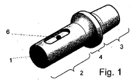
歯科インプラントを形成するための図1のコア要素1は、本質的に公知の態様で、移植後の状態において骨内にアンカー固定されるアンカー固定部2と、アンカー固定部2と一体の、クラウンまたは別の要素を取付けるための組立部3とを有する。拡張部4が移行領域に形成されており、拡張部4は、たとえば、移植後に歯茎上に支持される封止肩部を形成可能である。当業者であれば、本発明の教示内容は、別個のアバットメントを有する二部分からなる装置用のインプラント金型をも含む歯科インプラント用の他のインプラント金型にも容易に適用可能であり、さらに、機械的エネルギによって、かつインプラントの液化可能材料の少なくとも部分的な液化状態で移植可能な非歯科用インプラントにも容易に適用可能であることを容易に認識するであろう。
The core element 1 of FIG. 1 for forming a dental implant is in an essentially known manner an anchoring
一例として、コア要素は、たとえば酸化ジルコニウム系のチタン物質またはセラミック物質から製造される。 As an example, the core element is made of, for example, a zirconium oxide-based titanium material or a ceramic material.
2つのスロット状凹部6がアンカー固定部2の領域に存在している(図中には一方の凹部しか見えず、第2の凹部は、図中には見えない第1の凹部の反対側の領域にある)。この凹部の基部は粗面化される。残りの骨内表面領域(すなわち、移植後の状態において骨組織によって囲まれるアンカー固定部の表面領域)も少なくとも部分的に粗面化され得、この残りの表面領域の粗度はオッセオインテグレーションのために最適化される。この残りの表面領域の粗度の平均深さはたとえば1μm〜10μmであり、粗度の最大深さはたとえば3μm〜15μmである。
Two slot-
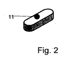
図2のアンカー固定要素11は、示される当初の状態では、スロット6と形状が一致しており、厚みはスロットの深さよりも大きい。エネルギ方向伝達部などの特定の構造は存在する必要がない。
In the initial state shown, the anchoring
一例として、アンカー固定要素11は吸収可能または吸収不可能な(任意に添加物を含む)熱可塑性ポリマー、たとえばポリ乳酸(PLA)またはポリメチルメタクリレート(PMMA)から製造される。
As an example, the anchoring
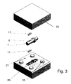
図3は、上述の種類のコア要素1および2つのアンカー固定要素11に加えて、二部分からなるネガ型を示す。分離面に沿って分離された2つの金型部21、22は、ともにネガ型を形成する。ネガ型は、たとえばシリコーン物質などの弾性材料から製造される。ネガ型の2つの部分21、22を接合することによって、すべての構造とともに製造されるインプラントの形状を有するキャビティ23がその内部に、すなわちより特定的にはエネルギ方向伝達部も有して形成される。金型部21、22は金型芯出し手段(位置決め補助器具)も有し得、これによって金型部の相対位置が正確に規定され得る。この場合、位置決め補助器具は、第1の金型部の円錐形の位置決め突起25の形状を有し、これは、接合されると、第2の金型部の対応する凹部(図示せず)に嵌まる。
FIG. 3 shows a two-part negative mold in addition to the core element 1 of the type described above and two anchoring
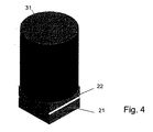
変形および/または接着処理を実行するため、図3に示すように、コア要素およびアンカー固定要素を意図した位置および向きでネガ型に挿入し、ネガ型を、たとえば温度を制御可能なオーブン内で変形高温に晒す。また、圧力を有利に印加し、これによって、若干弾性を有する金型部を互いに押付ける。図4に示す実施例では、これは重り31によって起こる。しかし、たとえば静水圧、油圧または空気圧などの圧力を印加する他のメカニズムも可能である。
To perform the deformation and / or bonding process, the core element and anchoring element are inserted into the negative mold in the intended position and orientation as shown in FIG. Exposure to high deformation temperatures. Also, pressure is advantageously applied, thereby pressing the slightly elastic mold parts together. In the embodiment shown in FIG. 4, this is caused by the
その後、ネガ型を、組立後の状態のまま、かつ好ましくは加圧下のまま、徐冷する。これは、オーブン温度を制御可能な態様で低下させることによって、またはオーブンから金型を取出して、たとえば室温などの周囲温度で徐冷することによってもたらされ得る。 Thereafter, the negative mold is gradually cooled in the state after assembling, and preferably under pressure. This can be effected by lowering the oven temperature in a controllable manner or by removing the mold from the oven and allowing it to cool slowly at ambient temperature, such as room temperature.
その後、2つの金型部を互いに分離することによって、形成されたインプラントを金型から取出す。 Thereafter, the formed implant is removed from the mold by separating the two mold parts from each other.
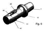
形成されたインプラントを図5に示す。図面の上部にあり、コア要素1に着実に接着している、アンカー固定要素11に形成された構造が、示される例示的な実施例において明らかに見られる。遠位方向に突出する2つの先端41の形態のエネルギ方向伝達部、およびそこから近位に配置された軸方向に延在するリブ42が見られる。
The formed implant is shown in FIG. The structure formed in the anchoring
実施例1
アンカー固定要素を製造するために、プレートに予め圧入する、Boehringer Ingelheim社の吸収可能なポリ乳酸LR706を使用する。Resomer(登録商標)LR706はL-ラクチドとR-ポリマーの混合物であり、ガラス転移温度は50°〜60°、液化温度は170℃〜210℃である。
Example 1
To produce the anchoring element, Boehringer Ingelheim absorbable polylactic acid LR706, pre-pressed into the plate, is used. Resomer® LR706 is a mixture of L-lactide and R-polymer with a glass transition temperature of 50 ° -60 ° and a liquefaction temperature of 170 ° C-210 ° C.
適切な外側寸法を有する細片(たとえば図2参照)を、従来のミリングマシンを用いてプレート材料からミリング加工する。これらの細片はアンカー固定要素になる。 A strip having the appropriate outer dimensions (see, eg, FIG. 2) is milled from the plate material using a conventional milling machine. These strips become anchoring elements.
ネガ型を製造するため、コンピュータ援用設計(CAD)システムを用いてポジ型を成形し、次に当該金型をステレオリソグラフィによって層毎に作る。このように形成したポジ型を、Simed社の二成分シリコーンDublosil(歯科用技術における複製集団としてしばしば用いられる)で充填する。完全に連結した後、それぞれのネガ型によって2つのシリコーンブロックが得られ、これらは、ネガまたはポジの金型芯出し手段(位置決め補助器具)も有する。2つの金型部のショア硬度は、24〜26ショアAである。 To produce a negative mold, a positive mold is molded using a computer aided design (CAD) system, and then the mold is made layer by layer by stereolithography. The positive mold thus formed is filled with Simed's two-component silicone Dublosil (often used as a replicating population in dental technology). After complete joining, each negative mold gives two silicone blocks, which also have negative or positive mold centering means (positioning aids). The Shore hardness of the two mold parts is 24 to 26 Shore A.
コア要素は、直径4mmで骨内長さ10mmのサンドブラスト仕上げされた表面を有する、等級4チタンからなる。また、インプラント本体には、幅1.5mm、長さ5mmおよび深さ0.5mmの2つのスロットが設けられる(図1参照)。
The core element consists of
第1のアンカー固定要素をインプラント本体(すなわちコア要素)上に置き、インプラント本体とともに、与えられた金型の片方に入れる。次に、第2の細片をコア要素の上側に置き、金型のもう1つの片方によって閉じる。質量500グラムの鋼鉄シリンダを重りとして用いる。 The first anchoring element is placed on the implant body (ie, core element) and placed with the implant body in one of the given molds. The second strip is then placed on top of the core element and closed by the other side of the mold. A steel cylinder with a mass of 500 grams is used as the weight.
パッケージ全体を、従来の手法でインキュベータ内で30分間130度まで加熱した後、オーブン外部の空気中で20分間冷却するが、重りは用いたままである。 The entire package is heated to 130 degrees in an incubator for 30 minutes in a conventional manner and then cooled for 20 minutes in air outside the oven, but the weight remains used.
これによって、所望のエネルギ方向伝達部と、コア要素とアンカー固定要素との優れた密接な接続とを有するインプラントが得られる。 This results in an implant having the desired energy direction transmission and an excellent intimate connection between the core element and the anchoring element.
実施例2
実施例1と同様のコア要素を使用する。実施例1とは異なり、アンカー固定要素はアクリルガラスXT(PMMA;ガラス転移温度約115℃)から製造される。ネガ型は、硬度が32ショアAの、Zhermack社のElite Double32シリコーンから製造される。
Example 2
The same core elements as in Example 1 are used. Unlike Example 1, the anchoring element is made from acrylic glass XT (PMMA; glass transition temperature about 115 ° C.). The negative mold is made of Zhermack Elite Double 32 silicone with a hardness of 32 Shore A.
アンカー固定要素を、コア要素とともに、与えられたネガ型に入れ、ネガ型を閉じる。質量500グラムの鋼鉄シリンダを重りとして用いる。 The anchoring element together with the core element is placed in the given negative mold and the negative mold is closed. A steel cylinder with a mass of 500 grams is used as the weight.
パッケージ全体を、従来の手法でインキュベータ内で20分間140度まで加熱した後、オーブン外部の空気中で20分間冷却するが、重りは用いたままである。 The entire package is heated to 140 degrees in an incubator for 20 minutes in a conventional manner and then cooled for 20 minutes in air outside the oven, but the weight remains used.
この結果、同様に、所望のエネルギ方向伝達部と、コア要素とアンカー固定要素との密接な接続とを有するインプラントが得られる。 This likewise results in an implant having the desired energy direction transmission and a close connection between the core element and the anchoring element.
実施例3
実施例1と同様であるが、酸化ジルコニウム(10%未満の酸化イットリウムの成分を含む)からなるコア要素をコア要素として使用する。具体的には、イットリア安定化正方晶の、一部結晶質の二酸化ジルコニウムを使用する。ここで、使用する二酸化ジルコニウムセラミックは、「外科用インプラント−イットリア安定化正方晶ジルコニア(Y−TZP)系のセラミック材料」に関するISO規格13356:2008を満たす。
Example 3
As in Example 1, but using a core element made of zirconium oxide (containing less than 10% yttrium oxide component) as the core element. Specifically, yttria-stabilized tetragonal, partially crystalline zirconium dioxide is used. Here, the zirconium dioxide ceramic used satisfies ISO standard 13356: 2008 regarding “surgical implant-yttria stabilized tetragonal zirconia (Y-TZP) based ceramic material”.
コア要素とアンカー固定要素との間に、同様に良好な接続が存在する。金型が弾性を有するため、処理時にコア要素が機械的に損傷する危険性は低い。 There is likewise a good connection between the core element and the anchoring element. Due to the elasticity of the mold, the risk of mechanical damage to the core element during processing is low.
多くのさらなる実施例が可能である。したがって、たとえば、ネガ型は、互いに隣り合って、またはマトリックス形式で、またはいずれかの他の規則的もしくは不規則的な態様で配置された複数の内部キャビティを有し得、各内部キャビティは、対応する数のアンカー固定要素を有するコア要素毎に設けられる。 Many further embodiments are possible. Thus, for example, a negative mold may have a plurality of internal cavities arranged next to each other or in matrix form, or in any other regular or irregular manner, where each internal cavity is It is provided for each core element having a corresponding number of anchoring elements.
Claims (15)
第1の材料を有するコア要素(1)を提供するステップと、
前記インプラントのネガ型(21、22)を提供するステップと、
前記コア要素(1)、および熱可塑性を有する第2の材料からなる少なくとも1つのアンカー固定要素(11)を、前記ネガ型(21、22)の中に位置決めするステップと、
前記コア要素(1)および前記少なくとも1つのアンカー固定要素(11)が入った金型内部キャビティが形成されるように前記ネガ型(21、22)を封止し、高い変形温度を印加するステップとを備え、前記変形温度において、前記第2の材料は塑性的に変形可能であるか、粘性を有するか、液体であり、前記第1の材料は固体であり、前記方法はさらに、
前記コア要素(1)および前記アンカー固定要素(11)を有する前記ネガ型(21、22)を冷却するステップと、
前記コア要素(1)および前記コア要素(1)に取付けられた前記アンカー固定要素(11)を有する、得られた前記インプラントを、前記ネガ型(21、22)から取出すステップとを備える、方法。 An implant manufacturing method comprising:
Providing a core element (1) having a first material;
Providing a negative type (21, 22) of the implant;
Positioning said core element (1) and at least one anchoring element (11) made of a thermoplastic second material in said negative mold (21, 22);
Sealing the negative mold (21, 22) so as to form a mold internal cavity containing the core element (1) and the at least one anchoring element (11) and applying a high deformation temperature Wherein, at the deformation temperature, the second material is plastically deformable, viscous, or liquid, the first material is solid, and the method further comprises:
Cooling the negative mold (21, 22) comprising the core element (1) and the anchoring element (11);
Removing the resulting implant having the core element (1) and the anchoring element (11) attached to the core element (1) from the negative mold (21, 22). .
TD:TG+1/4*(TM−TG)<TD<TM
が当てはまる、先行する請求項のいずれかに記載の方法。 The deformation temperature T D is between the glass transition temperature T G and the liquefaction temperature T M of the second material. For example, for the deformation temperature, T D : T G + 1/4 * (T M −T G ) <T D <T M
A method according to any of the preceding claims, wherein:
Applications Claiming Priority (3)
| Application Number | Priority Date | Filing Date | Title |
|---|---|---|---|
| CH01906/09A CH702349A1 (en) | 2009-12-11 | 2009-12-11 | A process for the manufacture of implants. |
| CH1906/09 | 2009-12-11 | ||
| PCT/CH2010/000307 WO2011069271A1 (en) | 2009-12-11 | 2010-12-07 | Method for producing implants |
Publications (3)
| Publication Number | Publication Date |
|---|---|
| JP2013513402A true JP2013513402A (en) | 2013-04-22 |
| JP2013513402A5 JP2013513402A5 (en) | 2014-01-30 |
| JP5659239B2 JP5659239B2 (en) | 2015-01-28 |
Family
ID=42045379
Family Applications (1)
| Application Number | Title | Priority Date | Filing Date |
|---|---|---|---|
| JP2012542326A Expired - Fee Related JP5659239B2 (en) | 2009-12-11 | 2010-12-07 | Implant manufacturing method |
Country Status (5)
| Country | Link |
|---|---|
| US (1) | US9375294B2 (en) |
| EP (1) | EP2509531B1 (en) |
| JP (1) | JP5659239B2 (en) |
| CH (1) | CH702349A1 (en) |
| WO (1) | WO2011069271A1 (en) |
Citations (6)
| Publication number | Priority date | Publication date | Assignee | Title |
|---|---|---|---|---|
| JPH02209148A (en) * | 1989-02-08 | 1990-08-20 | Mitsubishi Mining & Cement Co Ltd | Artificial bone, artificial tooth, bone fixing screw and its production |
| JPH06125979A (en) * | 1992-03-31 | 1994-05-10 | Nisshin Steel Co Ltd | Metal sintered body for implant and manufacture thereof |
| JPH08131460A (en) * | 1994-11-10 | 1996-05-28 | Takeshi Masumoto | Artificial tooth root for dental purpose and its production |
| JP2000072572A (en) * | 1998-08-27 | 2000-03-07 | Agency Of Ind Science & Technol | Plastic ceramics and their production |
| JP2007522847A (en) * | 2004-02-20 | 2007-08-16 | ウッドウェルディング・アクチェンゲゼルシャフト | Implant transplanted into bone tissue, its production method and transplantation method |
| JP2009254808A (en) * | 2008-03-19 | 2009-11-05 | Tokuyama Dental Corp | Protective material for dental implant |
Family Cites Families (7)
| Publication number | Priority date | Publication date | Assignee | Title |
|---|---|---|---|---|
| US5507814A (en) * | 1994-03-30 | 1996-04-16 | Northwestern University | Orthopedic implant with self-reinforced mantle |
| JP3417230B2 (en) * | 1996-09-25 | 2003-06-16 | 信越化学工業株式会社 | Photocurable liquid silicone rubber composition for mold making |
| US7008226B2 (en) * | 2002-08-23 | 2006-03-07 | Woodwelding Ag | Implant, in particular a dental implant |
| EP1626752A2 (en) | 2003-05-16 | 2006-02-22 | Blue Membranes GmbH | Medical implants comprising biocompatible coatings |
| US7867426B2 (en) * | 2006-03-23 | 2011-01-11 | Ziran Bruce H | Method of forming a temporary implant |
| SE531569C2 (en) * | 2006-09-19 | 2009-05-26 | Centri Ab | Prosthetic product with composite material wall, and method of making the prosthetic product |
| WO2008095327A1 (en) | 2007-02-08 | 2008-08-14 | Woodwelding Ag | Implant, method of preparing an implant, implantation method, and kit of parts |
-
2009
- 2009-12-11 CH CH01906/09A patent/CH702349A1/en not_active Application Discontinuation
-
2010
- 2010-12-07 WO PCT/CH2010/000307 patent/WO2011069271A1/en active Application Filing
- 2010-12-07 US US13/514,099 patent/US9375294B2/en active Active
- 2010-12-07 EP EP10787990.0A patent/EP2509531B1/en not_active Not-in-force
- 2010-12-07 JP JP2012542326A patent/JP5659239B2/en not_active Expired - Fee Related
Patent Citations (6)
| Publication number | Priority date | Publication date | Assignee | Title |
|---|---|---|---|---|
| JPH02209148A (en) * | 1989-02-08 | 1990-08-20 | Mitsubishi Mining & Cement Co Ltd | Artificial bone, artificial tooth, bone fixing screw and its production |
| JPH06125979A (en) * | 1992-03-31 | 1994-05-10 | Nisshin Steel Co Ltd | Metal sintered body for implant and manufacture thereof |
| JPH08131460A (en) * | 1994-11-10 | 1996-05-28 | Takeshi Masumoto | Artificial tooth root for dental purpose and its production |
| JP2000072572A (en) * | 1998-08-27 | 2000-03-07 | Agency Of Ind Science & Technol | Plastic ceramics and their production |
| JP2007522847A (en) * | 2004-02-20 | 2007-08-16 | ウッドウェルディング・アクチェンゲゼルシャフト | Implant transplanted into bone tissue, its production method and transplantation method |
| JP2009254808A (en) * | 2008-03-19 | 2009-11-05 | Tokuyama Dental Corp | Protective material for dental implant |
Also Published As
| Publication number | Publication date |
|---|---|
| EP2509531A1 (en) | 2012-10-17 |
| CH702349A1 (en) | 2011-06-15 |
| EP2509531B1 (en) | 2014-06-18 |
| US9375294B2 (en) | 2016-06-28 |
| US20120292815A1 (en) | 2012-11-22 |
| JP5659239B2 (en) | 2015-01-28 |
| WO2011069271A1 (en) | 2011-06-16 |
Similar Documents
| Publication | Publication Date | Title |
|---|---|---|
| CN1136817C (en) | Film or diaphragm for covering bone defect, its making method and fixing nail | |
| CN1694675B (en) | Preparation for being fastened on a natural tooth part or tooth and corresponding fastening method | |
| JP5282868B2 (en) | Dental implant having a surface made of ceramic material | |
| JP2001030037A (en) | Die for uniformly pressing side face of material to be worked, artificial bone made of titanium or titanium alloy having high bio-compatibility | |
| KR100746738B1 (en) | Implant having good biocompatibility and esthetics, and manufacturing method therof | |
| JP2014124500A (en) | Implant body, abutment body, implant, and production method of implant | |
| EP2384775A2 (en) | Method for producing an artificial bone and artifical bone produced by the method | |
| JP5659239B2 (en) | Implant manufacturing method | |
| KR20080017665A (en) | Porous implant fixture with multiplicity shapes | |
| KR101985509B1 (en) | Internal hole filler of abutment for implant | |
| CN111989066A (en) | Attaching a dental implant, a dental abutment and a dental superstructure to each other | |
| KR102404210B1 (en) | Manufacturing method for integral ceramic implant using polymer insert | |
| WO2006099969A3 (en) | Method and device for the production of spinal implants | |
| KR101137940B1 (en) | Auditory Ossicles Shape Structure Of Ceramic Material And Manufacturing Method Of The Same | |
| Shibli et al. | Histological comparison of bone to implant contact in two types of dental implant surfaces: a single case study | |
| KR101886710B1 (en) | Dental prosthesis | |
| JP2021500186A (en) | Ceramic structures, methods and their use for dental applications | |
| JPH1043219A (en) | Semifinished product for manufacturing prosthesis to be embedded with accurate fit, manufacture therefor, manufacture for prosthesis to be embedded in bone cavity and coxa inner prosthesis | |
| CN111405880B (en) | Dental restoration moulding block and method for manufacturing a dental restoration component from a dental restoration moulding block | |
| KR101569119B1 (en) | Porous body having advanced machinability and the manufacturing and machining method of the same | |
| KR101367221B1 (en) | 3-dimension scaffold and manufacturing method of thesame | |
| EP4226891A1 (en) | Dental implant having form in which abutment and prothesis are integrally connected, and manufacturing method for same | |
| RU157440U1 (en) | BONE TISSUE IMPLANT IMPLANT | |
| TWI546058B (en) | Dental implant and method of making the same | |
| JP2006187447A (en) | Implant, and its manufacturing method |
Legal Events
| Date | Code | Title | Description |
|---|---|---|---|
| A711 | Notification of change in applicant |
Free format text: JAPANESE INTERMEDIATE CODE: A711 Effective date: 20130611 |
|
| A521 | Request for written amendment filed |
Free format text: JAPANESE INTERMEDIATE CODE: A523 Effective date: 20130611 Free format text: JAPANESE INTERMEDIATE CODE: A821 Effective date: 20130611 |
|
| A521 | Request for written amendment filed |
Free format text: JAPANESE INTERMEDIATE CODE: A523 Effective date: 20131206 |
|
| A621 | Written request for application examination |
Free format text: JAPANESE INTERMEDIATE CODE: A621 Effective date: 20131206 |
|
| A131 | Notification of reasons for refusal |
Free format text: JAPANESE INTERMEDIATE CODE: A131 Effective date: 20140715 |
|
| A977 | Report on retrieval |
Free format text: JAPANESE INTERMEDIATE CODE: A971007 Effective date: 20140718 |
|
| A521 | Request for written amendment filed |
Free format text: JAPANESE INTERMEDIATE CODE: A523 Effective date: 20141010 |
|
| TRDD | Decision of grant or rejection written | ||
| A01 | Written decision to grant a patent or to grant a registration (utility model) |
Free format text: JAPANESE INTERMEDIATE CODE: A01 Effective date: 20141104 |
|
| A61 | First payment of annual fees (during grant procedure) |
Free format text: JAPANESE INTERMEDIATE CODE: A61 Effective date: 20141201 |
|
| R150 | Certificate of patent or registration of utility model |
Ref document number: 5659239 Country of ref document: JP Free format text: JAPANESE INTERMEDIATE CODE: R150 |
|
| R250 | Receipt of annual fees |
Free format text: JAPANESE INTERMEDIATE CODE: R250 |
|
| R250 | Receipt of annual fees |
Free format text: JAPANESE INTERMEDIATE CODE: R250 |
|
| R250 | Receipt of annual fees |
Free format text: JAPANESE INTERMEDIATE CODE: R250 |
|
| R250 | Receipt of annual fees |
Free format text: JAPANESE INTERMEDIATE CODE: R250 |
|
| S111 | Request for change of ownership or part of ownership |
Free format text: JAPANESE INTERMEDIATE CODE: R313117 |
|
| S531 | Written request for registration of change of domicile |
Free format text: JAPANESE INTERMEDIATE CODE: R313531 |
|
| R350 | Written notification of registration of transfer |
Free format text: JAPANESE INTERMEDIATE CODE: R350 |
|
| R250 | Receipt of annual fees |
Free format text: JAPANESE INTERMEDIATE CODE: R250 |
|
| LAPS | Cancellation because of no payment of annual fees |