JP2013512014A - Method and apparatus for controlling dose application during irradiation - Google Patents
Method and apparatus for controlling dose application during irradiation Download PDFInfo
- Publication number
- JP2013512014A JP2013512014A JP2012540330A JP2012540330A JP2013512014A JP 2013512014 A JP2013512014 A JP 2013512014A JP 2012540330 A JP2012540330 A JP 2012540330A JP 2012540330 A JP2012540330 A JP 2012540330A JP 2013512014 A JP2013512014 A JP 2013512014A
- Authority
- JP
- Japan
- Prior art keywords
- grid position
- irradiation
- grid
- dose
- during
- Prior art date
- Legal status (The legal status is an assumption and is not a legal conclusion. Google has not performed a legal analysis and makes no representation as to the accuracy of the status listed.)
- Granted
Links
- 238000000034 method Methods 0.000 title claims abstract description 93
- 239000002245 particle Substances 0.000 claims abstract description 119
- 230000008569 process Effects 0.000 claims abstract description 9
- 230000001678 irradiating effect Effects 0.000 claims abstract description 6
- 230000008859 change Effects 0.000 claims description 60
- 238000011282 treatment Methods 0.000 claims description 38
- 230000006978 adaptation Effects 0.000 claims description 33
- 238000004364 calculation method Methods 0.000 claims description 20
- 230000006870 function Effects 0.000 claims description 20
- 231100000628 reference dose Toxicity 0.000 claims description 18
- 238000009826 distribution Methods 0.000 claims description 15
- 238000005286 illumination Methods 0.000 claims description 12
- 230000001419 dependent effect Effects 0.000 claims description 10
- 238000012937 correction Methods 0.000 claims description 8
- 238000002560 therapeutic procedure Methods 0.000 claims description 5
- 238000003384 imaging method Methods 0.000 claims description 2
- 231100000673 dose–response relationship Toxicity 0.000 claims 2
- 238000010884 ion-beam technique Methods 0.000 abstract description 23
- 206010028980 Neoplasm Diseases 0.000 description 31
- OKTJSMMVPCPJKN-UHFFFAOYSA-N Carbon Chemical compound [C] OKTJSMMVPCPJKN-UHFFFAOYSA-N 0.000 description 23
- 238000002591 computed tomography Methods 0.000 description 12
- 150000002500 ions Chemical class 0.000 description 12
- 230000000694 effects Effects 0.000 description 9
- 238000005457 optimization Methods 0.000 description 9
- 230000002829 reductive effect Effects 0.000 description 8
- 238000001959 radiotherapy Methods 0.000 description 7
- 229910052799 carbon Inorganic materials 0.000 description 6
- 238000004891 communication Methods 0.000 description 6
- 230000009466 transformation Effects 0.000 description 6
- -1 carbon ions Chemical class 0.000 description 5
- 238000010586 diagram Methods 0.000 description 5
- 238000005259 measurement Methods 0.000 description 5
- 230000003068 static effect Effects 0.000 description 5
- 210000001519 tissue Anatomy 0.000 description 5
- 230000003044 adaptive effect Effects 0.000 description 4
- 230000002411 adverse Effects 0.000 description 4
- 230000001186 cumulative effect Effects 0.000 description 4
- QRYFCNPYGUORTK-UHFFFAOYSA-N 4-(1,3-benzothiazol-2-yldisulfanyl)morpholine Chemical compound C1COCCN1SSC1=NC2=CC=CC=C2S1 QRYFCNPYGUORTK-UHFFFAOYSA-N 0.000 description 3
- 230000008901 benefit Effects 0.000 description 3
- 238000011156 evaluation Methods 0.000 description 3
- 239000012634 fragment Substances 0.000 description 3
- 230000035515 penetration Effects 0.000 description 3
- 230000029058 respiratory gaseous exchange Effects 0.000 description 3
- 230000001225 therapeutic effect Effects 0.000 description 3
- 238000003325 tomography Methods 0.000 description 3
- 238000000844 transformation Methods 0.000 description 3
- 238000011144 upstream manufacturing Methods 0.000 description 3
- 238000006243 chemical reaction Methods 0.000 description 2
- 210000000038 chest Anatomy 0.000 description 2
- 230000003111 delayed effect Effects 0.000 description 2
- 238000002474 experimental method Methods 0.000 description 2
- 238000000605 extraction Methods 0.000 description 2
- 208000020816 lung neoplasm Diseases 0.000 description 2
- 208000037841 lung tumor Diseases 0.000 description 2
- 210000000056 organ Anatomy 0.000 description 2
- 230000004044 response Effects 0.000 description 2
- 230000000284 resting effect Effects 0.000 description 2
- 238000004088 simulation Methods 0.000 description 2
- 238000003860 storage Methods 0.000 description 2
- 238000013519 translation Methods 0.000 description 2
- 238000012935 Averaging Methods 0.000 description 1
- 210000001015 abdomen Anatomy 0.000 description 1
- 239000006096 absorbing agent Substances 0.000 description 1
- 238000010171 animal model Methods 0.000 description 1
- 230000004071 biological effect Effects 0.000 description 1
- 238000004113 cell culture Methods 0.000 description 1
- 238000002512 chemotherapy Methods 0.000 description 1
- 238000013461 design Methods 0.000 description 1
- 238000003745 diagnosis Methods 0.000 description 1
- 230000002349 favourable effect Effects 0.000 description 1
- 230000002779 inactivation Effects 0.000 description 1
- 230000003993 interaction Effects 0.000 description 1
- 239000000463 material Substances 0.000 description 1
- 230000000116 mitigating effect Effects 0.000 description 1
- 238000012986 modification Methods 0.000 description 1
- 230000004048 modification Effects 0.000 description 1
- 229910052754 neon Inorganic materials 0.000 description 1
- 238000011369 optimal treatment Methods 0.000 description 1
- 230000036961 partial effect Effects 0.000 description 1
- 238000002600 positron emission tomography Methods 0.000 description 1
- 238000013442 quality metrics Methods 0.000 description 1
- 230000005855 radiation Effects 0.000 description 1
- 238000002271 resection Methods 0.000 description 1
- 230000000241 respiratory effect Effects 0.000 description 1
- 239000011163 secondary particle Substances 0.000 description 1
- 210000001154 skull base Anatomy 0.000 description 1
- 239000000126 substance Substances 0.000 description 1
- 230000001360 synchronised effect Effects 0.000 description 1
- 230000002123 temporal effect Effects 0.000 description 1
- 238000012546 transfer Methods 0.000 description 1
- 230000007704 transition Effects 0.000 description 1
Images


Classifications
-
- A—HUMAN NECESSITIES
- A61—MEDICAL OR VETERINARY SCIENCE; HYGIENE
- A61N—ELECTROTHERAPY; MAGNETOTHERAPY; RADIATION THERAPY; ULTRASOUND THERAPY
- A61N5/00—Radiation therapy
- A61N5/10—X-ray therapy; Gamma-ray therapy; Particle-irradiation therapy
- A61N5/1048—Monitoring, verifying, controlling systems and methods
-
- A—HUMAN NECESSITIES
- A61—MEDICAL OR VETERINARY SCIENCE; HYGIENE
- A61N—ELECTROTHERAPY; MAGNETOTHERAPY; RADIATION THERAPY; ULTRASOUND THERAPY
- A61N5/00—Radiation therapy
- A61N5/10—X-ray therapy; Gamma-ray therapy; Particle-irradiation therapy
- A61N5/1042—X-ray therapy; Gamma-ray therapy; Particle-irradiation therapy with spatial modulation of the radiation beam within the treatment head
- A61N5/1043—Scanning the radiation beam, e.g. spot scanning or raster scanning
-
- A—HUMAN NECESSITIES
- A61—MEDICAL OR VETERINARY SCIENCE; HYGIENE
- A61N—ELECTROTHERAPY; MAGNETOTHERAPY; RADIATION THERAPY; ULTRASOUND THERAPY
- A61N5/00—Radiation therapy
- A61N5/10—X-ray therapy; Gamma-ray therapy; Particle-irradiation therapy
- A61N5/1048—Monitoring, verifying, controlling systems and methods
- A61N5/1071—Monitoring, verifying, controlling systems and methods for verifying the dose delivered by the treatment plan
- A61N2005/1072—Monitoring, verifying, controlling systems and methods for verifying the dose delivered by the treatment plan taking into account movement of the target
-
- A—HUMAN NECESSITIES
- A61—MEDICAL OR VETERINARY SCIENCE; HYGIENE
- A61N—ELECTROTHERAPY; MAGNETOTHERAPY; RADIATION THERAPY; ULTRASOUND THERAPY
- A61N5/00—Radiation therapy
- A61N5/10—X-ray therapy; Gamma-ray therapy; Particle-irradiation therapy
- A61N2005/1085—X-ray therapy; Gamma-ray therapy; Particle-irradiation therapy characterised by the type of particles applied to the patient
- A61N2005/1087—Ions; Protons
-
- A—HUMAN NECESSITIES
- A61—MEDICAL OR VETERINARY SCIENCE; HYGIENE
- A61N—ELECTROTHERAPY; MAGNETOTHERAPY; RADIATION THERAPY; ULTRASOUND THERAPY
- A61N5/00—Radiation therapy
- A61N5/10—X-ray therapy; Gamma-ray therapy; Particle-irradiation therapy
- A61N5/1048—Monitoring, verifying, controlling systems and methods
- A61N5/1064—Monitoring, verifying, controlling systems and methods for adjusting radiation treatment in response to monitoring
- A61N5/1065—Beam adjustment
- A61N5/1067—Beam adjustment in real time, i.e. during treatment
Landscapes
- Health & Medical Sciences (AREA)
- Engineering & Computer Science (AREA)
- Biomedical Technology (AREA)
- Pathology (AREA)
- Nuclear Medicine, Radiotherapy & Molecular Imaging (AREA)
- Radiology & Medical Imaging (AREA)
- Life Sciences & Earth Sciences (AREA)
- Animal Behavior & Ethology (AREA)
- General Health & Medical Sciences (AREA)
- Public Health (AREA)
- Veterinary Medicine (AREA)
- Radiation-Therapy Devices (AREA)
Abstract
本発明は、可動標的ボリュームを走査するのに利用するエネルギービーム、特に細針状イオンビームによる体内の標的ボリュームの照射中に線量付与を制御する方法に関する。更に本発明は、方法を実現する構成要素を備える照射装置に関する。i番目のグリッド位置を照射する前に、照射プロセス中の線量が移動データを使用して判定され、この線量は既に前のグリッド位置(1<=k<i)の照射中のi番目のグリッド位置を含んでいる。その後、前のグリッド位置(1<=k<i)の照射中にi番目のグリッド位置を既に含む判定された線量に依存してi番目のグリッド位置に対する補償値が算出され、i番目のグリッド位置について決定された補償された粒子フルエンス(Fi comp)によりi番目のグリッド位置を照射するために、i番目のグリッド位置に対する補償値及び公称粒子フルエンスに依存してi番目のグリッド位置についての補償された粒子フルエンス(Fi comp)が算出される。The present invention relates to a method for controlling dosing during irradiation of a target volume in the body with an energy beam, in particular a fine needle ion beam, used to scan a movable target volume. The invention further relates to an irradiation device comprising components that implement the method. Before irradiating the i th grid position, the dose during the irradiation process is determined using the movement data, and this dose is already i th grid being irradiated at the previous grid position (1 <= k <i). Includes location. Thereafter, a compensation value for the i-th grid position is calculated depending on the determined dose already including the i-th grid position during irradiation of the previous grid position (1 <= k <i), and the i-th grid In order to illuminate the i-th grid position with the compensated particle fluence (F i comp ) determined for the position, the i-th grid position for the i-th grid position depends on the compensation value for the i-th grid position and the nominal particle fluence. A compensated particle fluence (F i comp ) is calculated.
Description
本発明は、移動する標的ボリュームを走査するのに利用するエネルギービーム、特に細針状イオンビームによる体内の標的ボリュームの照射中に線量付与を制御する方法及び対応する照射装置に関する。 The present invention relates to a method for controlling dose application during irradiation of a target volume in the body with an energy beam, in particular a fine needle ion beam, used for scanning a moving target volume and a corresponding irradiation device.
一般に腫瘍は、切除術、放射線療法及び化学療法又はそれらの方法の組合せを使用して治療される。放射線療法において、治療の目的は、周囲の正常な組織に対する悪影響を最小限にしつつ、腫瘍への局所的に高い線量を得ることである。この目的のため、エネルギー付与又は線量付与は、可能な限り腫瘍の形状に一致するように制御される。最近、侵入深さの関数としてのエネルギー付与又は線量付与が非常にシャープな最大値(ブラッグピークと呼ばれる)を有するために、光子の代わりにイオンを照射することによって良好な治療結果が得られている。そのような方法の1つは、ビームが専用のコリメータにより形成される、受動的ビーム付与として既知である。しかし、代わりに、高精度にイオンビームを収束し、細針状ビーム、すなわちいわゆる「ペンシルビーム」を使用して3次元的に腫瘍を走査すること(ラスタ走査法、スポット走査法、継続走査法)もまた可能である。ラスタ走査法において、ビームは、規定の期間の間グリッド位置上にあり、次のグリッド位置に移る間もオン状態に維持される。これに対して、スポット走査法において、ビームはグリッド位置間ではオフ状態にされる。継続走査法において、ビームは、グリッド位置上で静止することなくグリッド位置間を継続的に移動する。 In general, tumors are treated using resection, radiation therapy and chemotherapy or a combination of these methods. In radiation therapy, the purpose of treatment is to obtain a locally high dose to the tumor while minimizing adverse effects on surrounding normal tissue. For this purpose, energy application or dose application is controlled to match the shape of the tumor as much as possible. Recently, good treatment results have been obtained by irradiating ions instead of photons, as energy application or dose application as a function of penetration depth has a very sharp maximum (called Bragg peak) Yes. One such method is known as passive beam application, where the beam is formed by a dedicated collimator. However, instead, the ion beam is focused with high accuracy and the tumor is scanned three-dimensionally using a fine needle beam, that is, a so-called “pencil beam” (raster scanning method, spot scanning method, continuous scanning method). ) Is also possible. In raster scanning, the beam is on the grid position for a specified period and is kept on while moving to the next grid position. In contrast, in the spot scanning method, the beam is turned off between the grid positions. In continuous scanning, the beam moves continuously between grid positions without resting on the grid positions.
陽子以外では、他のイオン、特に炭素イオンが現在使用されている。場合によっては、ネオンイオンが更に採用される。これらのイオンを使用することにより、光子と比較して、細胞の不活性化に関してより高い生物学的効果比(RBE)を提供する。線量レベル、組織の種類、並びに何より粒子の種類及び粒子エネルギーに対する依存のために、深い腫瘍領域におけるRBEは一般に入口チャネルより高く、これは更なる治療上の利点を提供する。 Other than protons, other ions are currently used, especially carbon ions. In some cases, neon ions are further employed. Use of these ions provides a higher biological effect ratio (RBE) for cell inactivation compared to photons. Due to dose level, tissue type, and above all, dependence on particle type and particle energy, the RBE in deep tumor regions is generally higher than the entrance channel, which provides further therapeutic benefits.
近年、出願人は、 University of Heidelberg、German Cancer Research Center及びDresden−Rossendorf Research Centerと協力して、炭素イオン及び専用の照射計画を使用するラスタ走査照射に関して大きな臨床的成功を収めた。この方法の利点は、2次的な粒子の生成を阻止するための吸収体材料の必要性を事実上除去することにあり、何より受動ビーム照射と比較して、特に腫瘍近辺で、生成された線量分布が良好に一致することである。 In recent years, Applicants have had great clinical success with raster scanning irradiation using carbon ions and a dedicated irradiation plan in collaboration with the University of Heidelberg, German Cancer Research Center and Dresden-Rossendorf Research Center. The advantage of this method is that it virtually eliminates the need for absorber material to prevent the generation of secondary particles, most of all, especially in the vicinity of the tumor compared to passive beam irradiation. The dose distribution is in good agreement.
最初に、主に治療された腫瘍は、頭蓋底の領域における腫瘍及び脊柱に沿った腫瘍であった。それらの腫瘍の動きは、定位固定により無視しても構わないほど最小に軽減される。しかし、種々の療法センターにおいてラスタ走査法をより広範に臨床的に適用する計画は、ラスタ走査法を使用してイオンビーム、特に炭素イオンビームにより他の腫瘍も照射することを想定する。しかし、身体の胴領域の腫瘍は、特に患者の呼吸のためにより動きやすい。そのため、胸部全体及び腹部の一部は、場合によっては患者の心拍によっても移動し且つ形状が変化する。移動する腫瘍、一般に移動する標的ボリュームが走査法を使用して治療される場合、この動きがエネルギー付与の均一性に悪影響を及ぼす可能性があるという問題に直面する。模型を用いた実験は、走査ビームの照射中に標的ボリュームにおいて過剰付与及び過少付与が発生する可能性があるため、受動ビーム照射の際に採用されるように動きの大きさにより標的ボリュームを単に拡大しても最適な治療とはならないことを示している。 Initially, the mainly treated tumors were tumors in the skull base area and tumors along the spinal column. Their movement is reduced to a minimum that can be ignored by stereotaxic fixation. However, a broader clinical application of raster scanning at various therapeutic centers envisions using the raster scanning to irradiate other tumors with an ion beam, particularly a carbon ion beam. However, tumors in the torso area of the body are more mobile, especially for patient breathing. Therefore, the entire chest and a part of the abdomen may move and change shape depending on the heartbeat of the patient. When moving tumors, generally moving target volumes, are treated using scanning techniques, we face the problem that this movement can adversely affect energy delivery uniformity. In experiments using the model, there is a possibility that overloading and underloading may occur in the target volume during the irradiation of the scanning beam, so the target volume is simply set according to the size of the movement as employed in the passive beam irradiation. It shows that even if enlarged, it is not an optimal treatment.
走査ビームの照射中の動きの影響を補正するため、現在、安全余裕、複数回照射(「再走査」と呼ばれる)、動きの様相に依存した中断を含む照射(「ゲーティング」と呼ばれる)、能動ビーム適応による動き補償照射(「トラッキング」と呼ばれる)又は上述の方法/技術の組合せを利用する分割照射法が前臨床試験で研究され且つ使用されている。能動ビーム適応による動き補償照射(トラッキング)中、ビーム位置は、腫瘍の動きに合わせて継続的に調整される。この処理において、ビーム方向に関する横(ラテラル)位置と、粒子の範囲とは、腫瘍の動きに合わせて継続的に調整される。これに関連して、全ての内容が参考として本明細書に取り入れられるS. O. Groetzinger 「Volume Conformal Irradiation of Moving Target Volumes with scnanned ion beams(走査イオンビームでの移動する標的ボリュームの体積等角照射)」、Technical University of Darmstadt、Germany、2004年の学位論文及びC. Bert、「Bestrahlungsplanung fuer bewegte Zielvolumina in der Tumortherapie mit gescanntem Kohlenstoffstrahl」、(Irradiation Planning for Moving Target Volumes in Tumor Therapy with a Scanned Ion Beam(走査イオンビームによる腫瘍治療における移動する標的ボリュームの照射計画))、Technical University of Darmstadt、Germany、2006年の学位論文を参照する。いずれの場合も、動き補償ラスタ走査イオンビーム照射は、本質的に粒子ビーム腫瘍療法の当業者に既知である。 To compensate for the effects of movement during irradiation of the scanning beam, safety margins, multiple irradiations (referred to as “rescan”), irradiation including interruptions that depend on the appearance of the movement (referred to as “gating”), Motion-compensated irradiation with active beam adaptation (referred to as “tracking”) or segmented irradiation methods utilizing combinations of the methods / techniques described above have been studied and used in preclinical studies. During motion compensated irradiation (tracking) with active beam adaptation, the beam position is continuously adjusted to the movement of the tumor. In this process, the lateral position with respect to the beam direction and the particle range are continuously adjusted according to the movement of the tumor. In this connection, the entire contents of S.C. are incorporated herein by reference. O. Groetzinger "Volume Conformation Irradiation of Moving Target Volumes with Scanned Ion Beams", Technical University of D. 4th, Technical University of Gart. Bert, "Bestrahlungsplanung fuer bewegte Zielvolumina in der Tumortherapie mit gescanntem Kohlenstoffstrahl", (Irradiation Planning for Moving Target Volumes in Tumor Therapy with a Scanned Ion Beam (irradiation planning target volume to be moved in tumor therapy by the scanning ion beam)), Technical University of of Darmstadt, Germany, see the 2006 dissertation. In either case, motion compensated raster scanning ion beam irradiation is essentially known to those skilled in the art of particle beam tumor therapy.
従って、対策(「動きの緩和」)が取られない場合、走査粒子ビームによる移動する腫瘍の治療は、基本的に動的照射と運動する構造との相互作用により線量誤差を招く可能性がある。能動ビーム適応(トラッキング)等の上述の方法が使用される場合でも、例えば単純な並進によって腫瘍の動きが記述できない場合、組織における粒子ビームの経路は、ビームの適応にもかかわらず変化するだろう。実際に、例えば胸郭の動きは回転要素及び/又は組織の変形を含みうるため、これは多くの場合に当てはまる。能動ビーム適応(トラッキング)により、ブラッグピーク、すなわち粒子線量の大部分の位置を解剖学的に正確な位置に移動できるが、ビーム経路が変化する結果、特に隣接領域、すなわちブラッグピークが存在するグリッド位置の上流にある、残りの組織への線量寄与が変化する。これにより、計画された線量付与と比較して局所的な過少付与及び過剰付与が生じるため、これは欠点となりうる。測定された肺腫瘍データに基づく治療シミュレーションにおいて、本発明者は、上述した線量変化を考慮しないことには、仮想上の静止した肺腫瘍のシミュレーション照射(線量変化が全く起こらない静的照射)と比較して、線量付与範囲が実質的に劣ることが分かった。 Therefore, if no countermeasures ("motion mitigation") are taken, the treatment of moving tumors with a scanning particle beam can result in dose errors due to the interaction between dynamic irradiation and moving structures basically. . Even when the above methods such as active beam adaptation (tracking) are used, the path of the particle beam in the tissue will change despite the adaptation of the beam if, for example, the translation of the tumor cannot be described by simple translation . In practice, this is often the case, for example because the movement of the thorax can include rotational elements and / or tissue deformation. Active beam adaptation (tracking) can move the position of most of the Bragg peak, ie the particle dose, to an anatomically correct position, but the beam path changes, resulting in a grid with particularly adjacent regions, ie Bragg peaks The dose contribution to the remaining tissue upstream of the location changes. This can be a drawback because it results in local under- and over-delivery compared to planned dose application. In the treatment simulation based on the measured lung tumor data, the present inventor does not consider the above-described dose change, and does not consider simulation irradiation of a static stationary lung tumor (static irradiation in which no dose change occurs). In comparison, the dose application range was found to be substantially inferior.
本発明は、特にこれらの問題を解決することを目的とする。 The present invention specifically aims to solve these problems.
独国特許出願公開第10 2005 063 220 A1号明細書は、照射の時間経過を改善する手段を記載しているが、これは、上述の課題に関してさらに改善されることが可能である。
上記を鑑みて、本発明の目的は、移動する標的ボリュームへの照射の品質を向上させ、且つ動きにもかかわらず照射中の実際の線量分布と所定の所望の線量分布との間での適切な一致を実現する線量付与の方法及び装置を提供することである。 In view of the above, the object of the present invention is to improve the quality of the irradiation of the moving target volume and to ensure that the actual dose distribution during the irradiation and the predetermined desired dose distribution in spite of movement. It is an object of the present invention to provide a dosing method and apparatus that achieves good agreement.
本発明の別の目的は、照射手順を最適化する線量付与の方法及び装置を提供することである。 Another object of the present invention is to provide a dosing method and apparatus that optimizes the irradiation procedure.
本発明の目的は、独立請求項の主題により実現される。本発明の有利な改良点は、従属請求項において特定される。 The object of the invention is realized by the subject matter of the independent claims. Advantageous refinements of the invention are specified in the dependent claims.
本発明によると、体内の移動する標的ボリュームは、走査法を使用してエネルギービームにより照射される。身体は、腫瘍を治療するために照射される人間又は動物の生体、患者の照射を検査するためのモデル(動物モデル、細胞培養又は他の模型)、あるいは別の非生体のいずれかであってもよい。ビームは、特に、粒子ビーム、好ましくは例えば高エネルギー炭素イオンビーム等のイオンビームである。本発明は、特に、例えばビーム照射の品質及び精度、並びに必要な演算能力の態様が標的ボリュームの動きにもかかわらず考慮されるように照射装置を制御することに関する。本発明によると、標的ボリュームが複数のグリッド位置に3次元的に分割され、且つこれらのグリッド位置が高精度の細針状イオンビームにより連続して走査される走査法が使用される。この方法は、「走査法」として当業者に既知である。本明細書において上述したように、ある特定の放射線量を受ける複数のグリッド位置(例えば、ビーム経路に配置されたグリッド位置)が常に存在するが、「i番目のグリッド位置の照射」という用語がブラッグピークが置かれる位置、すなわち最大線量を受けるグリッド位置を示すことは、当業者には明らかとなるだろう。従って、走査法において、加速器制御装置は、グリッド位置の関数として制御される粒子エネルギー及び粒子フルエンス(単位面積毎の粒子の数)を含むイオンビームにより個々のグリッド位置が連続して走査されるようにイオンビームを制御するため、グリッド位置に依存する線量は対応するグリッド位置において付与される。本発明は、特に背景技術において詳細に説明されたラスタ走査法及びスポット走査法に適している。 According to the present invention, a moving target volume in the body is illuminated by an energy beam using a scanning method. The body can be either a human or animal living body that is irradiated to treat the tumor, a model (animal model, cell culture or other model) for examining patient irradiation, or another non-living body. Also good. The beam is in particular a particle beam, preferably an ion beam, for example a high energy carbon ion beam. The invention relates in particular to controlling the irradiation device such that aspects of the beam irradiation quality and accuracy and the required computing power are taken into account despite the movement of the target volume. According to the present invention, a scanning method is used in which the target volume is three-dimensionally divided into a plurality of grid positions, and these grid positions are continuously scanned with a fine needle ion beam. This method is known to those skilled in the art as a “scan method”. As described herein above, there are always a plurality of grid positions (eg, grid positions arranged in the beam path) that receive a certain radiation dose, but the term “irradiation of the i-th grid position” It will be apparent to those skilled in the art to indicate the location where the Bragg peak is located, i.e. the grid location that receives the maximum dose. Thus, in the scanning method, the accelerator controller allows the individual grid positions to be continuously scanned by an ion beam including particle energy and particle fluence (number of particles per unit area) controlled as a function of grid position. In order to control the ion beam, the dose depending on the grid position is applied at the corresponding grid position. The present invention is particularly suitable for the raster scanning method and the spot scanning method described in detail in the background art.
これらの走査法において、最初に、照射される身体の、より具体的には標的ボリューム(例えば、腫瘍)の時間分解構造が、呼吸等により発生する可能性のある身体の動きの影響下で記録される。記録は、例えば時間分解3次元コンピュータ断層撮影システム(4D−CTとして既知である)、時間分解3次元磁気共鳴断層撮影システム(4D−MRTとして既知である)又は時間分解3次元ポジトロン放出断層撮影システム(4D−PETとして既知である)等の時間分解3次元撮影できる診断システムを使用して照射前に実行される。これに関連して、以下の手順が使用されてもよい。 In these scans, first the time-resolved structure of the irradiated body, more specifically the target volume (eg tumor), is recorded under the influence of body movements that may occur due to breathing etc. Is done. The recording can be, for example, a time-resolved 3D computed tomography system (known as 4D-CT), a time-resolved 3D magnetic resonance tomography system (known as 4D-MRT), or a time-resolved 3D positron emission tomography system. Performed prior to irradiation using a diagnostic system capable of time-resolved 3D imaging, such as (known as 4D-PET). In this connection, the following procedure may be used.
1)4D−CTスキャン(すなわち、動きの代わりとの時間的な相関によって、呼吸サイクルにおいて時間に従って並べられた複数の3D−CTスキャン(動き相M))を実行する手順 1) Procedure for performing 4D-CT scans (ie, multiple 3D-CT scans (motion phase M) aligned according to time in the respiratory cycle with temporal correlation with motion alternatives)
2)必要に応じて、4D−MRT/4D−PET走査(分割、ステージング)を実行する手順 2) Procedure for executing 4D-MRT / 4D-PET scanning (division, staging) as necessary
3)特に呼気中に、基準動き相を規定する手順 3) Procedure for defining the reference motion phase, especially during expiration
4)(非剛体)変換により、M−1個の動き相を基準動き相に登録する手順(例えばいわゆる「正規化された相互情報」が最小化される最適化処理)。結果として得られるM−1個の変換(及びそれらの逆)は、腫瘍の3D動きを説明できる。 4) A procedure for registering M−1 motion phases as reference motion phases by (non-rigid body) transformation (for example, an optimization process that minimizes so-called “normalized mutual information”). The resulting M-1 transformations (and vice versa) can explain the 3D motion of the tumor.
5)4D−CTスキャンの(3次元)基準相、並びに、(4D)−MRスキャン、コントラストCTスキャン、又は4D−CTスキャンから区切られたボリューム(腫瘍及びリスク臓器(OAR))を使用して準静的照射計画を最適化する手順。一般にこれは、例えばKraemer他の「Treatment planning for heavy−ion radiotherapy: physical beam model and dose optimation(重イオン放射線治療のための治療計画:物理ビームモデル及び線量最適化)」Phys Med Biol 2000年、45:33299−3317、Kraemer他の「Treatment planning for heavy−ion radiotherapy: calculation and optimization of biologically effective dose(重イオン放射線治療のための治療計画:生物学的有効線量の算出及び最適化)」Phys Med Biol 2000年、45:3319−3330、Jaekel及びKraemerの「Treatment planning for heavy ion Iraddiation(重イオン照射のための治療計画)」、Phys. Med. 14 53−62により当業者に既知である。 5) Using the (3-D) reference phase of the 4D-CT scan and the volume (tumor and risk organ (OAR)) delimited from the (4D) -MR scan, contrast CT scan, or 4D-CT scan Procedure to optimize quasi-static irradiation plan. In general, this is the case with Kraemer et al., “Treatment planning for heavy-ion radiotherapy: physical beam model and dose optimization” Phys Phys. : 33299-3317, Kraemer et al., “Treatment planning for heavy-ion radiotherapy: calculation and optimization of biologic dose effective for biomedical treatment and dose optimization. 2000, 45: 3319-3330, Jaekel and Kraemer, “Treatment planning for heavy ion irradiation”, Phys. Med. 14 53-62 known to those skilled in the art.
6)全てのグリッド点及び全ての相に対して適応パラメータdx、dy、dEを判定するように、基準照射計画と、変換パラメータと、4D−CT相とを組み合わせる手順 6) A procedure for combining the reference irradiation plan, the conversion parameter, and the 4D-CT phase so as to determine the adaptive parameters dx, dy, and dE for all grid points and all phases.
7)以下においてDik mと示される、動き相mの関数としてのグリッド点i〜グリッド点kの線量寄与を判定する手順 7) Procedure for determining dose contribution from grid point i to grid point k as a function of motion phase m, denoted D ik m in the following
8)以下において更に詳細に説明される照射方法を使用して照射を開始する手順 8) Procedure for starting irradiation using the irradiation method described in more detail below.
当業者には既知であるように、照射前に、コンピュータを含む照射計画装置を使用していわゆる照射計画が作成される。この目的のため、少なくとも4つの要素、すなわちx位置、y位置、粒子エネルギー及び粒子フルエンスを含むデータタプルは、動き相ごとに分解された方法で、1つ以上の照射サイクルにわたりグリッド位置毎に生成される。複数のグリッド位置及び問題の複雑さにより、生成処理に相対的に長い時間かかる可能性があるため、一般に照射計画は、場合によっては照射の数時間又は数日前に、全体が作成され且つ格納される。既知の方法において、一般に患者は、所定の照射計画からの値を使用して照射される。 As is known to those skilled in the art, before irradiation, a so-called irradiation plan is created using an irradiation planning device including a computer. For this purpose, a data tuple containing at least four elements, i.e. x-position, y-position, particle energy and particle fluence, is generated for each grid position over one or more irradiation cycles in a decomposed manner for each motion phase. Is done. Due to the multiple grid locations and the complexity of the problem, the generation process can take a relatively long time, so an irradiation plan is generally created and stored, sometimes hours or days before the irradiation. The In known methods, the patient is typically irradiated using values from a predetermined irradiation plan.
4Dデータに基づいて、当業者に既知である登録アルゴリズム(上記の4の説明を参照)を使用して個々の動き相間の(非剛体)変換、すなわち動きデータを判定することが可能である。換言すると、4DCT動き相に基づいて、パラメータを基準動き相に変換することが判定され且つ位置適応パラメータの形式で格納される複数の時間間隔が規定される。これらの時間間隔は、(M−1)個の動き相により規定される間隔と同一であってもよい。更なる時間間隔を導入することが更に考えられる。従って、動き相は、4D−CT/4D−MRTデータから取得される。その後登録は、例えば呼気から吸気に変化する変換を最適化する。 Based on 4D data, it is possible to determine (non-rigid) transformations between individual motion phases, ie motion data, using registration algorithms known to those skilled in the art (see description of 4 above). In other words, based on the 4DCT motion phase, it is determined to convert the parameter to the reference motion phase, and a plurality of time intervals stored in the form of position adaptive parameters are defined. These time intervals may be the same as the intervals defined by (M−1) motion phases. It is further conceivable to introduce further time intervals. Therefore, the motion phase is obtained from 4D-CT / 4D-MRT data. The registration then optimizes the conversion, eg changing from exhalation to inspiration.
このデータに基づいて、後で実行される照射中、動きの影響下でブラッグピークにより実際に到達される標的ボリュームのグリッド位置は、身体の動き測定値に基づいてリアルタイムで判定される。その後、使用可能になった補償パラメータにより、「正しい」位置に到達することが可能になる。 Based on this data, the grid position of the target volume that is actually reached by the Bragg peak under the influence of motion during subsequent irradiation is determined in real time based on body motion measurements. Thereafter, the compensation parameters that become available make it possible to reach the “correct” position.
本発明によると、照射計画は照射前に更に作成される。これに関連して、データタプルのデータセットは基準データセットに対応し、基準データセットにおいては、本発明に従って、照射計画における粒子フルエンスが、後で照射手順に従う照射中にリアルタイムで変更される公称粒子フルエンスに対応する。従って、標的ボリュームの複数のグリッド位置i、1<=i<=Nを含む照射計画が作成され且つ格納される。照射計画は、各グリッド位置iの照射に対してそれぞれのグリッド位置及びグリッド位置に依存する公称粒子フルエンスを含む基準データセットを含む。 According to the invention, the irradiation plan is further created before irradiation. In this connection, the data set of data tuples corresponds to a reference data set, in which the particle fluence in the irradiation plan is later changed in real time during irradiation according to the irradiation procedure according to the invention. Corresponds to particle fluence. Accordingly, an irradiation plan including a plurality of grid positions i, 1 <= i <= N, of the target volume is created and stored. The irradiation plan includes a reference data set that includes a respective grid position and a nominal particle fluence that depends on the grid position for irradiation at each grid position i.
照射中、照射時間中のあらゆる時間において、どの動き相が存在するのかを判定するために、身体の動きは、動き感知装置により継続的に捕捉される。これに基づいて、グリッド位置の実際の動きは、4D−CT又は4D−MRTの実験等から取得された位置適応パラメータに基づいて照射中に連続して3次元的に判定される。 Body motion is continuously captured by the motion sensing device to determine which motion phase is present during irradiation, at any time during the irradiation time. Based on this, the actual movement of the grid position is determined three-dimensionally continuously during irradiation based on position adaptive parameters obtained from 4D-CT or 4D-MRT experiments or the like.
この目的のため、本発明は、照射中、照射前に格納されたデータセットを読み出し、且つ、変更された値で、特に変更された粒子フルエンスで、迅速に後続して照射を実行するように、リアルタイムで前記データセットを変更させる演算装置を含む。 For this purpose, the invention reads out the data set stored before irradiation during irradiation and performs subsequent irradiation quickly with changed values, in particular with changed particle fluence. And an arithmetic unit for changing the data set in real time.
一般に照射計画はN個のグリッド位置を含み、数Nは数千〜数万又はそれ以上でもよい。本発明によると、以下において更に詳細に説明されるように、他の照射中のi番目のグリッド位置、グリッド位置kの照射中に判定された動き相において、前に照射された他のk番目のグリッド位置1<=k<iの照射中にi番目のグリッド位置によって受け取られた、実際に付与された粒子フルエンスが、i番目のグリッド位置1<=i<=N毎に判定され且つ処理される。本発明によると、オンライン、すなわちリアルタイムでこれらの計算を実行できるように、以下のステップi1)〜i4)がi番目のグリッド位置毎に実行され、この場合1<=i<=Nである。一方、一般に1つのグリッド位置の照射は、数ミリ秒しかかからない。従って、データが多次元であるため、高い計算能力が必要なのは明らかである。
In general, the irradiation plan includes N grid positions, where the number N may be thousands to tens of thousands or more. According to the present invention, as will be explained in more detail below, in the motion phase determined during the irradiation of another irradiation i-th grid position, grid position k, the other k-th previously irradiated The actual imparted particle fluence received by the i-th grid position during the irradiation of the
i1)前のグリッド位置(1<=k<i)の照射中にi番目の位置により既に受けた線量が、相互線量寄与を含む、以前に(すなわち、オフラインで)作成されたデータベース及び動きデータを使用して、照射サイクル中にリアルタイムで演算装置により算出される。 i1) Previously (ie, off-line) database and motion data where the dose already received by the i th location during irradiation of the previous grid location (1 <= k <i) includes a mutual dose contribution Is calculated by the arithmetic unit in real time during the irradiation cycle.
i2)ステップi1)の後及び特にi番目のグリッド位置の照射の直前、i番目のグリッド位置に対する補償値が、i番目のグリッド位置が前のグリッド位置(1<=k<i)の照射中に既に受けていると判定される線量に基づいて演算装置により算出される。 i2) After step i1) and immediately before the irradiation of the i-th grid position, the compensation value for the i-th grid position is being irradiated at the grid position where the i-th grid position is the previous (1 <= k <i). Is calculated by the arithmetic unit based on the dose determined to have already been received.
i3)i2)の後及びi番目のグリッド位置の照射の直前、補償された粒子フルエンスFi compを含む変化したデータタプルは、i番目のグリッド位置に対する補償値、及び照射計画においてi番目のグリッド位置に対して規定された公称粒子フルエンスi nomを含む基準データタプルに基づいて、i番目のグリッド位置に対して算出される。 i3) After i2) and immediately before irradiation of the i th grid position, the changed data tuple containing the compensated particle fluence F i comp is the compensation value for the i th grid position and the i th grid in the irradiation plan. Calculated for the i th grid position based on a reference data tuple containing a nominal particle fluence i nom defined for the position.
i4)その後、i番目のグリッド位置は、リアルタイムで算出される補償粒子フルエンスFi compにより照射される。 i4) Thereafter, the i-th grid position is illuminated by a compensation particle fluence F i comp calculated in real time.
本発明の方法を使用して、標的ボリュームの動きにもかかわらず十分な線量有効範囲を実現でき、所望の値からの局所的な偏差を減少できることにより実際に付与された線量分布に対する動きの影響を軽減することが可能になる。 Using the method of the present invention, sufficient dose coverage can be achieved in spite of target volume movement and the local deviation from the desired value can be reduced so that the effect of movement on the actual applied dose distribution. Can be reduced.
特に、i番目のグリッド位置に対する補償値の計算は、i−1番目のグリッド位置の照射中に実行される。 In particular, the calculation of the compensation value for the i th grid position is performed during irradiation of the i−1 th grid position.
照射中、前に照射された全てのグリッド位置kの照射中にi番目のグリッド位置が受けた線量変化が全てのk<iにわたり合計され、且つi番目のグリッド位置の照射に対する補償値が、線量変化(実際の線量と基準線量との差)の合計から、i−1番目のグリッド位置の照射中に算出されるのが好ましい。 During irradiation, the dose changes experienced by the i th grid position during irradiation of all previously irradiated grid positions k are summed over all k <i, and the compensation value for irradiation of the i th grid position is It is preferable to calculate from the sum of dose changes (difference between actual dose and reference dose) during irradiation of the (i-1) th grid position.
本発明の好適な一実施形態によると、i番目のグリッド位置に対する補償値は、全ての前のk番目のグリッド位置の照射中にi番目のグリッド位置が受けた合計線量変化がi番目のグリッド位置に対する特定の基準線量で正規化された相対補正係数として演算装置により算出されるため、無次元補正係数である。この補償係数は、治療制御システムのサブシステム、すなわちSKTと呼ばれる粒子フルエンス制御サブシステムに格納され、その後照射が実行されるi番目のグリッド位置に対して補償された粒子フルエンス(Fi comp)を算出するために、i番目のグリッド位置の照射に先立って、i番目のグリッド位置に対する補償値として粒子フルエンス制御サブシステムのメモリに読み込まれ、且つその後、依然としてi番目のグリッド位置の照射前に、照射計画においてi番目のグリッド位置に対して規定された公称粒子フルエンスによりリアルタイムで乗算される。このことは、補償値を、線量測定等のために日常的に変化する校正係数とは独立とすることができるために有利である。 According to a preferred embodiment of the invention, the compensation value for the i th grid position is the total dose change received by the i th grid position during the irradiation of all previous k th grid positions. Since it is calculated by the arithmetic unit as a relative correction coefficient normalized with a specific reference dose with respect to the position, it is a dimensionless correction coefficient. This compensation factor is stored in a treatment control system subsystem, a particle fluence control subsystem called SKT, and the compensated particle fluence (F i comp ) for the i th grid position after which irradiation is performed. To calculate, prior to the irradiation of the i th grid position, it is read into the particle fluence control subsystem memory as a compensation value for the i th grid position, and then still before the irradiation of the i th grid position, Multiplied in real time by the nominal particle fluence defined for the ith grid position in the irradiation plan. This is advantageous because the compensation value can be independent of calibration factors that change routinely for dose measurements and the like.
i番目のグリッド位置の照射の直前に粒子フルエンス制御サブシステムによりi番目のグリッド位置に対する補償値をメモリからロードできるように、粒子フルエンス制御サブシステムSKTが全てのグリッド位置について適用された粒子フルエンスを制御し、且つ演算装置がi−1番目のグリッド位置の照射中にi番目のグリッド位置についての補償値を粒子フルエンス制御サブシステムSKTのメモリに格納するのが有利である。次にサブシステムSKTは、i番目のグリッド位置に対する補償された粒子フルエンスによりi番目のグリッド位置を後続して照射するように、照射計画においてi番目のグリッド位置に対して規定された公称粒子フルエンスにリアルタイムで補償値を適用する。 The particle fluence control subsystem SKT has applied the particle fluence applied for all grid positions so that the compensation value for the i th grid position can be loaded from memory by the particle fluence control subsystem immediately before irradiation of the i th grid position. Advantageously, the computing device stores the compensation value for the i th grid position in the memory of the particle fluence control subsystem SKT during the irradiation of the i−1 th grid position. The subsystem SKT then irradiates the i-th grid position subsequently with the compensated particle fluence for the i-th grid position so that the nominal particle fluence defined for the i-th grid position in the irradiation plan. Apply compensation values in real time.
i番目のグリッド位置の照射計画の開始時に、i番目のグリッド位置に対する補償値がサブシステムのメモリにまだ格納されていない場合、i番目のグリッド位置が不正確な粒子フルエンスにより照射されるのを阻止するように、少なくともi番目のグリッド位置に対する補償値が格納されるまで、ビーム強度を変動するかあるいはビーム休止を導入することが可能だろう。 At the start of the irradiation plan for the i-th grid position, if the compensation value for the i-th grid position is not yet stored in the subsystem memory, the i-th grid position is irradiated by an inaccurate particle fluence. To prevent, it would be possible to vary the beam intensity or introduce beam pause until a compensation value for at least the i-th grid position is stored.
i番目のグリッド位置の照射中、線量変化は全ての後続のグリッド位置o、i<o<=Nに対して同時に算出されないが、線量変化及び補償値は、計算能力を最適に利用し且つ補償値が可能な限り早く使用可能であることを保証するように、最初にi+1番目のグリッド位置のみに対して算出されるのが好ましい。後続のグリッド位置i+1<o<=Nに対する線量変化及び補償値は、i番目のグリッド位置に対する補償値がサブシステムのメモリに格納されるまで算出されない。 During the irradiation of the i-th grid position, the dose change is not calculated simultaneously for all subsequent grid positions o, i <o <= N, but the dose change and the compensation value optimally use the computational power and compensate In order to ensure that the value can be used as soon as possible, it is preferably calculated initially only for the i + 1 th grid position. Dose changes and compensation values for subsequent grid positions i + 1 <o <= N are not calculated until the compensation values for the i-th grid position are stored in the subsystem memory.
あるいは、i番目のグリッド位置の照射中、i番目のグリッド位置に配置される等エネルギー層のグリッド位置に対する線量変化を算出し、且つ等エネルギー層間の照射のビーム休止(いわゆる「スピル休止」)中に、後続の等エネルギー層のグリッド位置に対する線量変化を算出するのが好都合だろう。 Alternatively, during irradiation of the i-th grid position, a change in dose with respect to the grid position of the equal energy layer arranged at the i-th grid position is calculated, and irradiation pause of the irradiation between the equal energy layers (so-called “spill pause”) In addition, it may be convenient to calculate the dose change with respect to the grid position of the subsequent isoenergetic layer.
前のk番目のグリッド位置の照射中に、既に照射計画においてi番目のグリッド位置に対して規定された基準線量以上の線量変化をi番目のグリッド位置が既に受けている場合がある。この場合、i番目のグリッド位置の照射は、スキップされるかあるいは照射前に決定された最小線量で実行される。後者は、ビーム位置を継続的に制御する場合に有利だろう。この目的のため、最小線量は、基準線量の1%以上及び30%以下であるのが好ましい。 During irradiation of the previous k-th grid position, the i-th grid position may already have received a dose change that is equal to or greater than the reference dose defined for the i-th grid position in the irradiation plan. In this case, irradiation at the i-th grid position is skipped or executed with a minimum dose determined before irradiation. The latter may be advantageous when continuously controlling the beam position. For this purpose, the minimum dose is preferably not less than 1% and not more than 30% of the reference dose.
また、照射中、グリッド位置に依存してビームの強度を各グリッド位置に適用される粒子フルエンスへと調整するのが有利である。これにより、可能な限り高速な照射、すなわち低い誤り率を有し且つ緩やかな照射を実現するように補償を算出するのに使用可能な時間が可能な限りバランスを保ち且つ/あるいは最小値へと近づけられるように、グリッド位置の照射時間を等しくすることが可能になる。 Also, during irradiation, it is advantageous to adjust the beam intensity to the particle fluence applied to each grid location depending on the grid location. This ensures that the time available to calculate the compensation to achieve the fastest possible illumination, i.e. low error rate and gradual illumination, is as balanced as possible and / or to a minimum. It is possible to make the irradiation times of the grid positions equal so that they can be approached.
一般に、等エネルギー層の照射はビームパケット(いわゆる「スピル」)により実行され、次の等エネルギー層は、次のビームパケット(スピル)のみにより照射される。この点に関して、品質指標Qを規定するのが有利である。品質指標Qに基づいて、次のビームパケット(スピル)の開始は自動的に最適な動き相と同期される。この目的のため、演算装置は、種々の動き相に対する次のビームパケット(スピル)についての後続するグリッド位置に対する、グリッド位置に依存する粒子フルエンスの分布を算出し、例えば以下の評価基準に基づいて品質指標を利用して同期化を自動的に評価する。 In general, the irradiation of the equal energy layer is performed by a beam packet (so-called “spill”), and the next equal energy layer is irradiated only by the next beam packet (spill). In this regard, it is advantageous to define a quality index Q. Based on the quality index Q, the start of the next beam packet (spill) is automatically synchronized with the optimal motion phase. For this purpose, the computing device calculates the distribution of particle fluences dependent on the grid position for the subsequent grid position for the next beam packet (spill) for the various motion phases, for example based on the following evaluation criteria: Automatically evaluate synchronization using quality metrics.
以下の評価基準又はこれらの基準の(場合によっては重み付き)組合せのうちの少なくとも1つは、品質指標Qに含まれるのが好ましい。 At least one of the following evaluation criteria or a (possibly weighted) combination of these criteria is preferably included in the quality index Q.
i)各グリッド位置についての補償された粒子フルエンスの類似度。各グリッド点の照射回数が可能な限り類似していることはこの場合の優位性であり、これは利用可能な演算時間に関してもその通りである。 i) Compensated particle fluence similarity for each grid position. It is an advantage in this case that the number of irradiations of each grid point is as similar as possible, and this is also true for the available computation time.
ii)基準線量の粒子フルエンスからの補償された粒子フルエンスの偏差は可能な限り小さい。従って、必要に応じて干渉による影響が軽減されるだろう。 ii) The deviation of the compensated particle fluence from the reference dose particle fluence is as small as possible. Therefore, the effects of interference will be reduced if necessary.
iii)後続のグリッド位置への潜在的な過剰付与が減少する。これにより、可能な限り基準値に近接する線量をグリッド位置毎に実現することが可能になる。 iii) Potential overloading to subsequent grid locations is reduced. This makes it possible to realize a dose as close as possible to the reference value for each grid position.
iv)関連付けられた動き相に到達することが予想されるまでの時間。一般に、グリッド位置の平均照射時間はミリ秒の範囲であり、層の平均照射時間は秒の範囲であり、断片の平均照射時間は分の範囲である。従って、動き相は、グリッド位置を照射する時間より大幅に長くてもよい。従って、次のビームパケット(スピル)による照射の開始が非常に長く遅延する場合、これは品質指標に対する更なる重み係数となるだろう。 iv) The time until it is expected to reach the associated motion phase. In general, the average irradiation time of the grid position is in the range of milliseconds, the average irradiation time of the layer is in the range of seconds, and the average irradiation time of the fragments is in the range of minutes. Thus, the motion phase may be significantly longer than the time to illuminate the grid position. Thus, if the start of irradiation by the next beam packet (spill) is delayed very long, this will be an additional weighting factor for the quality indicator.
本発明は、ビームを動きに能動適応すること(トラッキング)と組み合わされてもよいが、これはまたより複雑でない代替案である。本発明の好適な一使用例において、能動ビーム適応(トラッキング)は長さ方向ではなく横(ラテラル)方向に実行される。これは、グリッド位置に依存する補償値が動きの代わりの測定により判定された動き相及び照射計画中に判定されたパラメータに基づいて判定されることを意味する。しかし、横方向ビーム位置のみが能動的に適応され、これは走査磁石対を使用して相対的に容易に達成される。これに対して、ビームエネルギーは能動的に適応されないが、本発明の方法は、長さ方向次元での能動適応がないことを補償する。 The present invention may be combined with active adaptation of the beam to motion (tracking), but this is also a less complex alternative. In one preferred use of the invention, active beam adaptation (tracking) is performed in the lateral direction rather than the length direction. This means that the compensation value depending on the grid position is determined based on the motion phase determined by measurement instead of motion and the parameters determined during the irradiation plan. However, only the lateral beam position is actively accommodated, which is relatively easily achieved using a scanning magnet pair. In contrast, although beam energy is not actively adapted, the method of the present invention compensates for the lack of active adaptation in the longitudinal dimension.
本発明の効果は、1つの断片におけるグリッド位置が連続して複数回走査される(再走査)複数回照射技術に類似する、複数のサイクルにおいて実行された照射と組み合わせることにより更に向上する。従って、各照射サイクルにおいて、照射は僅かな基準線量で実行される。この方法において、前回の照射サイクルにおいてi番目のグリッド位置が受けた線量変化及び現在の照射サイクルにおいて前のグリッド位置の照射中にi番目のグリッド位置が受けた線量変化は、照射サイクルにおいてi番目のグリッド位置に対する補償係数を算出する際に考慮される。このように、実際の線量分布は所望の線量分布へとより適切に適応される。例えば断片毎に計画された線量の0.1%、1%又は10%の線量許容誤差を受け入れること等により、照射サイクルの数は、集合的なデータ及び動きパラメータに基づいて事前に最適化されるか、患者特有のものであるか、あるいは照射中に判定されうる。許容量がこの値を下回ると、照射は終了する。終了するための他の決定的な要因は、不均一なグリッド(等エネルギー層毎の、複数の隔離されたグリッド点)を照射する機能等の技術的な限界条件であってもよい。 The effect of the present invention is further improved by combining with irradiation performed in multiple cycles, similar to a multiple irradiation technique in which the grid position in a piece is continuously scanned multiple times (rescan). Thus, in each irradiation cycle, irradiation is performed with a small reference dose. In this method, the dose change received by the i th grid position in the previous irradiation cycle and the dose change received by the i th grid position during irradiation of the previous grid position in the current irradiation cycle are i th This is taken into account when calculating the compensation coefficient for the grid position. In this way, the actual dose distribution is more appropriately adapted to the desired dose distribution. The number of irradiation cycles is pre-optimized based on collective data and motion parameters, for example by accepting a dose tolerance of 0.1%, 1% or 10% of the planned dose per fragment. Or patient-specific or can be determined during irradiation. When the allowable amount falls below this value, the irradiation ends. Another critical factor for termination may be a technical limit condition such as the ability to illuminate a non-uniform grid (multiple isolated grid points per isoenergetic layer).
以下において、例示的な実施形態に基づいて且つ図面を参照して、本発明を更に詳細に説明する。同一の部分又は同様の部分は部分的に同一の図中符号を提供され、種々の例示的な実施形態の特徴は互いに組み合わされる。 In the following, the invention will be described in more detail on the basis of exemplary embodiments and with reference to the drawings. Identical or similar parts are provided with partially identical reference numerals, and the features of the various exemplary embodiments are combined with one another.
図面において、
図1を参照すると、種々のビームに対する深部線量分布が示される。ビルドアップ効果後に線量が深さに関して指数関数的低下を示す光子(曲線12)とは異なり、イオンは、ビーム範囲の端部でブラッグピーク又はブラッグ最大値と呼ばれる顕著な線量最大値を示す。この最大値は、エネルギーを変動させることにより深さをシフトすることができる。ブラッグピークは、陽子(曲線18)の場合よりも炭素イオン(曲線14及び16)の場合により急峻であることが分かる。 Referring to FIG. 1, the depth dose distribution for various beams is shown. Unlike photons (curve 12) where the dose shows an exponential drop in depth after the build-up effect, the ions show a significant dose maximum called the Bragg peak or Bragg maximum at the end of the beam range. This maximum value can be shifted in depth by varying the energy. It can be seen that the Bragg peak is steeper for carbon ions (curves 14 and 16) than for protons (curve 18).
図2は、身体において標的ボリュームに照射する例示的な照射装置20の設計を示す概略図である。照射装置は、この例において2つの粒子源又はイオン源22a、22bを有する加速器21を含む。2つの粒子源又はイオン源22a、22bは種々のイオンを生成し、その低エネルギー中間イオンビーム23は、磁石24を切り替えることにより、線形前段加速器25に注入される。中間イオンビーム23は、線形前段加速器25により前段加速され、例えばシンクロトロン等の円形加速器26に注入される。あるいは、サイクロトロン、すなわちいわゆる「誘電体壁加速器」又はレーザベースの加速器を使用することも可能である。いくつかの加速器は、例えばガントリ上の照射室に直接設置することも可能であるため、別個のビームガイダンスシステムは必要ない。
FIG. 2 is a schematic diagram illustrating an
円形加速器26は、最後にイオンを治療エネルギーと等しいか又はそれより僅かに高い所望のエネルギーに加速する。次に、イオンビーム又は治療ビーム27は、円形加速器26から抽出され、ビーム案内手段28により照射室29a、29b、29cに入射される。照射室29a、29b、29cの各々において、イオンビーム27により身体30を照射できる。炭素イオンにより照射する場合、治療ビーム27の粒子エネルギーは約80〜50MeV/uの範囲である。2つの左の照射室29a、29bにおいて、身体30の標的ボリューム32は、ほぼイオンビーム27が照射室29a、29bに入射する方向に照射される。右の照射室29cは回転ガントリ29dと呼ばれるものを備え、これは標的ボリューム32を種々方向から照射することを可能とする(アイソセントリック照射)。身体30は患者等であり、標的ボリューム32は治療目的で照射される腫瘍である。しかし、更に身体は、腫瘍照射を検査するための模型であってもよく、例えば標的ボリュームは、照射される検出器又は異なる物質であってもよい。
図3は、動きセンサ及び演算装置を含む時間分解3次元撮影断層撮影システム42、例えばいわゆる4D−CTシステム又は4D−MRTシステムを示す。断層診断システムは、患者の呼吸等の身体30の動きの影響下で腫瘍等の標的ボリューム32の3次元の動きを記録し、動きデータをM個の動き相に分割する。次にコンピュータ44は、照射前に、付与される所望の合計線量に基づいて照射計画46を作成する。照射計画は、照射されるグリッド位置毎に位置及び公称粒子フルエンスのデータを含む。
FIG. 3 shows a time-resolved three-
更にコンピュータ44は、動き相m(1<=m<=M)毎に3次元位置適応パラメータ(Δxi、Δyi、ΔEi)を含む位置適応テーブルを作成するため、この位置適応テーブルに基づき且つ身体の動きを認識することにより、それぞれの個々のグリッド位置の実際の位置及び/又は基準動き相m=refにおける基準位置からの実際の位置の偏差を算出することが可能である。これに関連して、Δxiは、基準相m=refにおけるグリッド位置iのx位置からの、動き相mにおけるグリッド位置iの横方向(ラテラル)x位置の偏差を表す。同様に、Δyiは、他の横(ラテラル)方向、すなわちy方向の偏差を規定する。ΔEiは、ブラッグピークをグリッド位置iの基準位置から実際の位置へとシフトさせる、イオンエネルギーの偏差、すなわち長さ方向の位置適応パラメータを規定する。
Further, the
図4は、能動動き補償を含む照射を示す簡略化された概略図である。加速器21は、2つの対の走査磁石52、54を利用して標的ボリューム32にわたり横方向(ラテラル)に走査される治療ビーム27を提供する。標的ボリュームは、連続して走査される複数の等エネルギー層に分割され、ここでは318〜324に分割される。一般に、遠位の等エネルギー層から近位の等エネルギー層へと走査する、すなわち最も高いエネルギーから開始するのが好都合である。図4に示された時点で、等エネルギー層322は横方向(ラテラル)に走査されている。標的ボリューム32が矢印33により表されるように移動し且つ現在照射されているグリッド位置iの動きが既知である場合、ビーム位置は、標的ボリューム32の動きにもかかわらず意図したグリッド位置iに到達するために、走査磁石52、54を利用して横方向(ラテラル)に且つダブルウェッジシステム56を利用して長さ方向に、標的ボリューム32の動きに能動的に適応される。現在照射されているグリッド位置iの実際の位置は、身体30の動きを捕捉する動き感知装置58及び治療制御システム70に格納された位置適応テーブルを利用して判定される。
FIG. 4 is a simplified schematic diagram illustrating illumination including active motion compensation. The
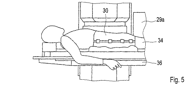
図5は、照射室29a等における患者台36上の患者34を示す。あるいは、患者34ではなく模型等の異なる身体30が照射されてもよい。
FIG. 5 shows the patient 34 on the patient table 36 in the
図6aにおいて、グリッド位置iが現在照射されている。これは、ビームが横方向(ラテラル)にはグリッド位置iへ(x、y)に入射され、現在のグリッド位置iが配置される等エネルギー層322にブラッグピークが配置されるように粒子エネルギー(E)が選択されることを意味する。この範囲で、図6aは静止した標的ボリューム32の照射を示す。
In FIG. 6a, grid position i is currently illuminated. This is because the beam energy (lateral) is incident on the grid position i at (x, y), and the particle energy (the Bragg peak is arranged in the
急峻なブラッグピーク19aにもかかわらず、線量付与は、グリッド位置i以外のグリッド位置によっても受け取られ、特に、ビーム経路におけるブラッグピーク19aの上流の平坦域19bのグリッド位置によって受け取られ、より少ない量だが、グリッド位置iのブラッグピーク19aのビーム軸上の下流の位置、すなわちブラッグピーク19a背後の領域19cによっても受け取られることが、侵入深さzの関数としての線量付与19から明らかである。静止した標的ボリューム32の他のグリッド位置k0、k1及びk3〜k9におけるこれらの線量付与は、(「静的」)基準照射計画46において既に考慮されている。特に、照射前に作成された照射計画46は、グリッド位置毎に所定の線量付与を実現するために各グリッド位置において付与される粒子の数を規定するテーブルを含む。ブラッグピーク19aの上流の平坦域19b等のために他の全てのグリッド位置kの照射中にグリッド位置iが受けた線量付与は、標的ボリューム32が静止しているという仮定の下ではあるがこの照射計画46において既に考慮されている。
Despite the
標的ボリュームが例えば図6bに示されるように移動するため、照射されることを実際に意図するグリッド位置iが上方向に移動し且つ標的ボリュームが傾斜する場合、これにより、2つの悪影響が生じる。すなわち、2つの悪影響は、第1にブラッグピークが実際に照射されることを意図するグリッド位置iに到達しないこと、第2に標的ボリューム32を介するビーム経路が標的ボリュームの傾斜等により変化することである。また、標的ボリューム32が更に変形する可能性があるため、ビーム経路は更に変化する。
As the target volume moves, for example as shown in FIG. 6b, if the grid position i that is actually intended to be illuminated moves upward and the target volume tilts, this has two adverse effects. That is, the two adverse effects are that, firstly, the grid position i intended to be actually irradiated with the Bragg peak is not reached, and secondly, the beam path through the
図6cに示されるように、ビーム位置の能動適応により、ブラッグピーク19aをグリッド位置iに再度移すことが可能である。ビーム27を能動的に適応するこの方法は、一般に、当業者により既知であり、「トラッキング」と呼ばれる。また、図6cに更に示されるように、ビームは、図6aに係る静止した標的ボリュームの仮定の下に作成された照射計画における経路とは異なる標的ボリュームを介した経路を取るため、平坦域19b等の線量付与は、ビームが標的ボリューム32の動きに能動的に適応される場合であっても、静止した標的ボリュームの場合とは異なるグリッド位置kにおいて行われる。これらの付与誤差は、ビーム27の能動適応だけでは除去されず、静的照射計画46において考慮されない。これは、本発明が効果を示す点である。
As shown in FIG. 6c, active adaptation of the beam position allows the
以下において、本発明は、i、k等の変数により示される個々のグリッド位置又はそれらを互いに関連させるための他のプレースホルダーを参照して説明される。これらのプレースホルダーは、例えば1<=i<=N等の全てのグリッド位置を示すために変数として使用されることが明らかである。 In the following, the present invention will be described with reference to individual grid positions indicated by variables such as i, k, or other placeholders for associating them with one another. It is clear that these placeholders are used as variables to indicate all grid positions, for example 1 <= i <= N.
照射計画は、Nグリッド位置から構成され、M個の動き相を含む。図8に示された図を参照すると、動き相mにおいてグリッド位置iの照射中にグリッド位置kにおいて付与された線量は、照射前に事前に算出され、Dik mにより示される。これに関連して、グリッド位置iにおいて、照射計画に係る線量が付与されると仮定する。グリッド位置i毎に、これらの値は、依然として照射される全てのグリッド位置kについての照射前に、全ての可能な動き相1≦m≦Mについて算出される。図4を参照して説明されるように、遠位のグリッド位置の照射中に近位に発生する変化を、後続する近位のグリッド位置の照射中に補正できるように、一般に照射は、遠位から近位に実行される。
The irradiation plan is composed of N grid positions and includes M motion phases. Referring to the diagram shown in FIG. 8, the dose applied at grid position k during irradiation of grid position i in motion phase m is calculated in advance before irradiation and is denoted by D ik m . In this connection, it is assumed that a dose related to the irradiation plan is given at the grid position i. For each grid position i, these values are calculated for all
グリッド位置iの照射中、これによって後続して照射される全てのグリッド位置k(線量が依然として能動的に変化できる)に発生した線量変化Δdik m(i)は、以下の式を使用してそれぞれの個々のグリッド位置の動きの関数として本発明に従って算出される。 During irradiation of grid position i, the dose change Δd ik m (i) that occurs at all grid positions k that are subsequently irradiated (the dose can still be actively changed ) is calculated using the following equation: It is calculated according to the present invention as a function of the movement of each individual grid position.
式中、m(i)は、グリッド位置iの照射中に測定された動き相を示し、ΔDiは、照射方法において現時点までのグリッド位置iに対する累積線量変化を示す。累積線量変化は、グリッド位置iの前に照射された全てのグリッド位置の個々の寄与を合計することにより、照射中にリアルタイムで算出される。 In the equation, m (i) indicates a motion phase measured during irradiation at the grid position i, and ΔD i indicates a cumulative dose change with respect to the grid position i up to the present time in the irradiation method. The cumulative dose change is calculated in real time during irradiation by summing the individual contributions of all grid positions irradiated before grid position i.
従って、ΔDiはグリッド位置iにおける線量変化に関連し、補償値として使用できる。 Therefore, ΔD i is related to the dose change at grid position i and can be used as a compensation value.
式(1)の項ΔDi/Dii refにおいて、累積線量は、グリッド位置iが照射計画に従ってグリッド位置iの照射中に受けるはずの線量Dii refで正規化される。指標「ref」は基準相m=refを表す。動き相mの各々における各グリッド位置の実際の瞬間位置は、照射計画中に照射前に(オフラインで)作成された位置適応テーブルに基づいて算出される。 In the term ΔD i / D ii ref of equation (1), the cumulative dose is normalized by the dose D ii ref that the grid position i should receive during irradiation of the grid position i according to the irradiation plan. The index “ref” represents the reference phase m = ref. The actual instantaneous position of each grid position in each of the motion phases m is calculated based on a position adaptation table created before irradiation (offline) during the irradiation plan.
グリッド位置iの照射中、次のグリッド位置の正規化された、すなわち相対的な線量変化ΔDi+1/D(i+1)(i+1) refは、粒子フルエンス制御サブシステム(SKT)72に送信される(図7及び図9を参照)。照射制御システムにおいて、SKT72及び他の全てのサブシステム71、73、74、75の双方からアクセス可能なSKT72の通信メモリは、照射の進行中にこの目的のために使用される。他の加速器は、他の通信プロトコル及びリアルタイム通信対応の装置を更に使用してもよい。
During the irradiation of grid position i, the normalized or relative dose change ΔD i + 1 / D (i + 1) (i + 1) ref of the next grid position is sent to the particle fluence control subsystem (SKT) 72 ( (See FIGS. 7 and 9). In the irradiation control system, the communication memory of the
無次元の相対線量変化ΔDi/Dii refを補償値として使用することにより、SKT72は、線量単位を機械パラメータに変換する必要なく線量変化を適用できるのが有利である。更にこの相対量は、線量を監視するために使用されたイオン化室64の校正係数を日常的に変更することに左右されない。しかし、相対線量変化ではなく、線量変化ΔDiをSKTの対応する単位(機械パラメータ)に変換し且つこの絶対量を送信することが更に可能である。
By using the dimensionless relative dose change ΔD i / D ii ref as a compensation value, the
照射計画からの公称粒子フルエンスFi nomは、補償係数(1−ΔDi/Dii ref)により乗算される。すなわち、累積線量変化により補償された粒子フルエンスFi+1 comp=Fi+1 nom(1−ΔDi+1/D(i+1)(i+1) ref)が、次のグリッド位置i+1に適用される。 The nominal particle fluence F i nom from the irradiation plan is multiplied by the compensation factor (1−ΔD i / D ii ref ). That is, the particle fluence F i + 1 comp = F i + 1 nom (1−ΔD i + 1 / D (i + 1) (i + 1) ref ) compensated by the accumulated dose change is applied to the next grid position i + 1.
従って、補償された粒子フルエンスは、グリッド位置i+1が照射計画において規定された基準線量を少なくとも受けるために依然として必要な線量寄与を高精度に反映し、動き及びビーム経路の変化にもかかわらずこれを行う。それに応じて、式(1)の補償係数は、グリッド位置iの照射が基準線量ではなく、補償係数(1−ΔDi/Dii ref)により変化された線量で実行されることを反映する。 Thus, the compensated particle fluence accurately reflects the dose contribution still necessary for grid position i + 1 to receive at least the reference dose specified in the irradiation plan, and this is reflected in spite of motion and beam path changes. Do. Accordingly, the compensation factor of equation (1) reflects that the irradiation at grid position i is performed with a dose that is changed by the compensation factor (1-ΔD i / D ii ref ) rather than the reference dose.
図9に示されるフローチャートを参照すると、手順は以下の通りである。 Referring to the flowchart shown in FIG. 9, the procedure is as follows.
ブロック1:時間分解断層撮影走査(例えば4D CTスキャン等のいわゆる4D診断走査)が実行されるか、あるいは時間分解断層撮影データが3DCTスキャン及び患者特有のデータ又は集団的動きデータに基づいて算出される。 Block 1: Time-resolved tomographic scan (so-called 4D diagnostic scan such as 4D CT scan) is performed, or time-resolved tomographic data is calculated based on 3DCT scan and patient specific data or collective motion data The
ブロック2:照射前に、以下の手順に係る時間分解断層撮影走査のデータに基づく動き相m(いわゆる4D照射計画)を考慮して照射計画が実行される。 Block 2: Before irradiation, an irradiation plan is executed in consideration of the motion phase m (so-called 4D irradiation plan) based on time-resolved tomographic scan data according to the following procedure.
ブロック2a:データタプル(xi、yi、Ei、Ti)は、グリッド位置1<=i<=N毎に規定される。式中、xi及びyiは横方向(ラテラル)位置であり、Eiは粒子エネルギーであり、Tiはi番目のグリッド位置において付与される粒子の数である。粒子の数及び粒子フルエンスが交換可能な量であることは明らかである。それぞれN個のグリッド位置を含む1つ又はJ個の照射サイクルについて、照射前にこの規定が行われ、この結果は一般に照射計画と呼ばれる。
ブロック2b:位置適応パラメータは、時間分解断層撮影のデータに基づいてグリッド位置i及び動き相m(Δxi、Δyi、ΔEi)毎に規定される。これにより、動きの際のグリッド位置の実際の場所が、仮定的な休止状態に対応する、基準相m=refにおける基準位置にさかのぼって計算されることが可能となる。 Block 2b: Position adaptation parameters are defined for each grid position i and motion phase m (Δx i , Δy i , ΔE i ) based on time-resolved tomography data. This allows the actual location of the grid position in motion to be calculated retroactively to the reference position in the reference phase m = ref corresponding to the hypothetical resting state.
ブロック2c:線量補償パラメータDik mは、全ての組合せi、k=1...N及び全ての動き相m=1...Mに対して規定される。
この目的のため、以下のステップを実行する。 For this purpose, the following steps are performed.
必要に応じて、4D−MRT/4D−PET走査(分割、ステージング)を実行するステップ; Performing a 4D-MRT / 4D-PET scan (split, staging) as needed;
特に呼気中に基準動き相を規定するステップ; Defining a reference motion phase, especially during expiration;
4D−CTスキャンを使用できない場合、4D−CTスキャンを実行するステップ; If 4D-CT scan is not available, performing 4D-CT scan;
(非剛体)変換により、M−1個の動き相を基準動き相に対して表すステップ(例えばいわゆる「正規化された相互情報」が最小化されるような最適化処理)、結果として得られるM−1個の変換(及びそれらの逆)は、腫瘍の3D動きを説明できる; The (non-rigid) transformation results in the step of representing M-1 motion phases with respect to the reference motion phase (eg optimization process so that so-called “normalized mutual information” is minimized), resulting in M-1 transformations (and vice versa) can account for 3D motion of the tumor;
4D−CTスキャンの(3次元)基準相、及び(4D)−MRスキャン、コントラストCTスキャン又は4D−CTスキャンからの部分ボリューム(腫瘍及びリスク臓器(OAR))を使用して、準静的基準照射計画を最適化するステップ、一般にこれは、例えばKraemer他の「Treatment planning for heavy−ion radiotherapy: physical beam model and dose optimation(重イオン放射線治療のための治療計画:物理ビームモデル及び線量最適化)」Phys Med Biol 2000年、45:3329.9−3317、Kraemer他の「Treatment planning for heavy−ion radiotherapy: calculation and optimization of biologically effective dose(重イオン放射線治療のための治療計画:生物学的有効線量の算出及び最適化)」Phys Med Biol 2000年、45:3319−3330、Jaekel及びKraemer「Treatment planning for heavy ion Iraddiation(重イオン照射のための治療計画)」、Phys. Med. 14 53−62から当業者に既知であるれ Quasi-static reference using (3D) reference phase of 4D-CT scan and partial volume (tumor and risk organ (OAR)) from (4D) -MR scan, contrast CT scan or 4D-CT scan The step of optimizing the irradiation plan, generally this is for example the method of Kraemer et al. “Treatment planning for heavy-ion radiotherapy: physical beam model and dose optimization (physical beam radiation therapy) and dose optimization. Phys Med Biol 2000, 45: 3329.9-3317, Kraemer et al., “Treatment planning for heavy-ion radiotherap. y: calculation and optimization of biologically effective dose (treatment planning for heavy ion radiotherapy: calculation and optimization of biologically effective dose), Phys Med Biol 2000, 45: 3319-3330, Jaekel and KraemerTemmer for heavy ion irradiation ", Phys. Med. 14 53-62 known to those skilled in the art
全てのグリッド点及び全ての相に対して適応パラメータdx、dy、dEを決定するように、基準照射計画と、変換パラメータと、4D−CT相とを組み合わせるステップ; Combining the reference illumination plan, the transformation parameters and the 4D-CT phase to determine the adaptive parameters dx, dy, dE for all grid points and all phases;
動き相mの関数として、以下においてDik mと示されるグリッド点iからグリッド点kの線量寄与を判定するステップ。 Determining the dose contribution of the grid point k from the grid point i, denoted D ik m in the following, as a function of the motion phase m.
ブロック3:照射中、ステップ3a〜3dは、全ての1<=i<=Nにわたる全てのグリッド位置、及び当てはまるのであれば全ての照射サイクル1<=j<=Jに対して、位置4と5とを組み合わせてリアルタイムに実行される。
Block 3: During irradiation, steps 3a-3d are taken as position 4 for all grid positions over all 1 <= i <= N and, if applicable, all
ブロック3a:Δd(i)(i+1) m(i)は、ブロック2cからの線量補償パラメータに基づいて、且つ動き感知装置により捕捉されるブロック4からの動きデータの関数として算出される。
ブロック3b:無次元の相対的補償係数ΔDi+1/D(i+1)(i+1) refが算出される。
ブロック3c:無次元の相対的補償係数ΔDi+1/D(i+1)(i+1) refは、粒子フルエンス制御サブシステムSKTに送信され、位置5に係るSKTの通信メモリに格納される。
ブロック3d:Δdik m(i)は、さらに照射される全てのk>i+1に対して、ブロック2cからの線量補償パラメータDik mに基づいて、且つ動き感知装置により捕捉されるブロック4からの動きデータの関数として、算出される、
ブロック4:動きデータは、動き感知装置により捕捉される。 Block 4: Motion data is captured by a motion sensing device.
ブロック5:粒子フルエンスは、粒子フルエンス制御サブシステムSKT72により制御される。 Block 5: Particle fluence is controlled by the particle fluence control subsystem SKT72.
ブロック5a:線量変化ΔDi+1/D(i+1)(i+1) refは、SKTのメモリから読み出される。
ブロック5b:補償された粒子フルエンスFi compは、SKT72より算出される。
ブロック5c:グリッド位置i+1は、補償された粒子フルエンスFi compを用いて照射される。
従って、要約すると、補償値は、照射中にリアルタイムで算出され、照射計画において規定された公称粒子フルエンスの代わりに照射のために使用される補償された粒子フルエンスを取得するために、公称粒子フルエンスに適用される。補償値は、グリッド位置に固有の様式での動きの下で実際に適用された線量に依存し、こうしてグリッド位置依存しかつ動きに依存する。 Thus, in summary, the compensation value is calculated in real time during irradiation and is used to obtain the compensated particle fluence used for irradiation instead of the nominal particle fluence specified in the irradiation plan. Applies to The compensation value depends on the dose actually applied under the movement in a manner specific to the grid position and thus depends on the grid position and on the movement.
本発明は、好ましくはグリッド位置iの照射中に、SKTが補償値を適用する前に後続のグリッド位置i+1に対する補償値がSKTに送信されることを保証することにより、相対的に複雑な線量補償処理の時間経過を制御する解決方法を更に提供する。 The present invention preferably ensures that during the irradiation of grid position i, the compensation value for the subsequent grid position i + 1 is transmitted to the SKT before the SKT applies the compensation value. A solution for controlling the time course of the compensation process is further provided.
図7は、本発明を実現できる方法の一例を示す。加速器21により生成されたイオンビーム27は、ここでは等エネルギー層320〜324に分割されている標的ボリューム32に向けられ、矢印33により示されるように照射中に断片内を移動する。ビーム27は、走査磁石対52、54を用いて、標的ボリューム32にわたり横方向(ラテラル)に、すなわちx方向及びy方向に走査される。図示された時点で、ビームは等エネルギー層322にわたり走査されている。
FIG. 7 shows an example of how the present invention can be implemented. The
実際のビーム位置は、少なくとも1つの、この例においては2つの、マルチワイヤチャンバ62により監視され、位置データは、横方向(ラテラル)ビーム位置LSP73を監視するサブシステムに送信される。ビーム27の横方向(ラテラル)位置が十分な精度で照射計画46に係る位置に一致しない場合、LSP73はインターロックを発生させる。
The actual beam position is monitored by at least one, in this example two,
走査磁石SSM71を制御するサブシステムは、走査磁石を制御し、こうしてx方向及びy方向の横方向(ラテラル)グリッド位置を制御する。
The subsystem that controls the
粒子フルエンス制御サブシステムSKT72は、実際に付与された粒子数又は粒子フルエンスをチェックし、3倍に冗長となっていてもよいイオン化室64の援助により、照射計画46及び補償値に基づいて、現在のグリッド位置iが十分な粒子を受けており且つシステムが次のグリッド位置i+1に切り替えられる場合を判断する。切り替えコマンドは、モジュールSKT72により、特にモジュールSSM71に通信され、モジュールSSM71はそれに応じて走査磁石を制御する。モジュールSKT72はまた、等エネルギー層の終点を更に通信する。
The particle fluence
加速器KMB74を監視するサブシステムは、加速器21に対する制御装置82と通信する。この通信により、例えば治療制御システム70は、現在の等エネルギー層に対する粒子エネルギー、ビーム収束及びビーム強度を含む、現在必要とされるパラメータを有する次のビームパケット(スピル)についての要求を行う。本明細書において、サブシステム71から74に加え、治療制御システム70は、文書化のためのサブシステムDOK75、並びに照射計画46及び演算装置84を更に含む。
The subsystem that monitors the
等エネルギー層322の照射中、動き感知装置58は、身体30の動きを捕捉し、補償値を算出するためにこのデータを演算装置84に送信する。現在のグリッド位置iの照射中、次に演算装置84は、図3に従って作成された位置適応テーブル及び(「静的」)基準線量補償パラメータDik mに基づいてリアルタイムに、動きに依存する補償値ΔDi+1/D(i+1)(i+1) refを算出する。演算装置84は、照射計画46から線量補償パラメータDik mを取得する。演算装置84は、リアルタイムに、グリッド位置i毎に動きに依存する補償値ΔDi+1/D(i+1)(i+1) refをモジュールSKT72に転送する。照射計画46からの公称粒子フルエンス及び演算装置84からの補償値に基づいて、モジュールSKT72は、リアルタイムで補償された粒子フルエンスを算出してモジュールSSM71と通信し、これにより補償された粒子フルエンスが付与された際に次のグリッド位置i+1へと切り替わるようにビーム27を制御する。
During irradiation of the
本発明の例において、ビームを横方向(ラテラル)方向に適応させるためにΔx及びΔyを提供することにより、演算装置84がモジュールSSM71を制御し、且つモジュールSSM71が続けて走査磁石52及び54を制御するように、本発明に係る線量補償は、3次元能動ビーム適応と組み合わされる。更に演算装置84は、長さ方向ビーム適応を実行するために使用されるダブルウェッジシステム56又は能動エネルギー適応のための他の何らかのシステムを制御する。
In the example of the present invention, computing
本発明の例において、治療制御システム70はVME−BUSシステム76を含むため、モジュール71〜75は、VME−BUSバスを介して互いに通信できる。
In the example of the present invention,
有利な実施形態
本発明は、以下のように更に改良される。
Advantageous Embodiments The present invention is further improved as follows.
a)グリッド位置iの照射中、全ての後続のグリッド位置k>iに対する線量変化を算出し、次のグリッド位置i+1に対して累積された補償値をSKT72に後続して送信してそれをそこに格納するのではなく、最初に、次のグリッド位置i+1に対する線量変化寄与だけが算出され、このグリッド位置i+1について累積された補償値が続けて送信される。残りの全てのグリッド位置i+2<=k<=Nへの寄与が算出されるのはその後である。
a) During irradiation at grid position i, the dose change for all subsequent grid positions k> i is calculated and the accumulated compensation value for the next grid position i + 1 is transmitted following
これは、次のグリッド位置、この場合はi+1、の照射に対する補償値が、SKT72の通信メモリにおいて可能な限り早く使用可能であることを保証する。
This ensures that the compensation value for the irradiation of the next grid position, in this case i + 1, is available as soon as possible in the communication memory of the
b)グリッド位置iの照射中、同一の等エネルギー層のグリッド位置に対する線量変化のみが算出される。照射計画46における他の等エネルギー層における残りのグリッド位置への線量変化寄与は、後に遅くとも等エネルギー層についての完了の際に行われる照射休止(スピル休止)の間までは処理されない。この方法は、能動エネルギー変動を採用する加速器等に適している。この一例はシンクロトロンを含む加速器であり、照射される等エネルギー層を規定するビームエネルギーは、シンクロトロンにおいて能動的に変動する。これは、新しいビームパケット(スピル)の生成と関連付けられるため、ビーム休止は、いずれにしても等エネルギー層の照射の間に起こる。
b) During the irradiation of the grid position i, only the dose change for the grid position of the same isoenergy layer is calculated. Dose change contributions to the remaining grid positions in other isoenergetic layers in the
サイクロトロンを有する加速器等の他の加速器は、吸収プレートを利用してビームを規定する(受動エネルギー変動)。同様に、この場合、エネルギーを変動させるために吸収プレートを挿入及び/又は除去することは、ビーム休止と関連付けられる。このビーム休止は、照射計画における他の等エネルギー層において残りのグリッド位置への線量変化寄与を算出するために更に使用されてもよい。 Other accelerators, such as those with cyclotrons, use an absorbing plate to define the beam (passive energy fluctuation). Similarly, in this case, inserting and / or removing the absorbing plate to vary the energy is associated with beam pause. This beam pause may further be used to calculate the dose change contribution to the remaining grid positions in other isoenergetic layers in the irradiation plan.
他の等エネルギー層における残りのグリッド位置の線量変化寄与の算出を遅らせることにより、1つの等エネルギー層内のグリッド位置の連続照射の時間厳守局面の間の演算時間が短縮するため、必要な計算がグリッド位置の照射より長くかかる可能性が低下する。 Necessary calculation because the calculation time during the strict adherence phase of continuous irradiation of the grid positions in one isoenergy layer is shortened by delaying the calculation of the dose change contribution of the remaining grid positions in other isoenergy layers Is less likely to take longer than irradiation at the grid position.
オプションとして、全ての後続のグリッド位置の線量変化寄与を算出するための十分な時間が依然としてない場合、次のグリッド位置の照射は、計算が終わるまでビームを中断することにより遅延されてもよく、また、ビーム強度が低下させられてもよい。 Optionally, if there is still not enough time to calculate the dose change contribution for all subsequent grid positions, the irradiation of the next grid position may be delayed by interrupting the beam until the calculation is complete, Further, the beam intensity may be reduced.
c)また、補償値のための記憶位置がグリッド位置毎に確保されるメモリアレイを作成するのが有利である。すると補償値は、全てのグリッド位置についてメモリの同一の場所に書き込まれるのではなく、アレイにおけるグリッド位置毎の事前定義された記憶位置に書き込まれる。これにより、i番目のグリッド位置に対する補償値がメモリに書き込まれる前に読み出される場合に、これは例えば計算のための十分な時間がなく且つ計算のための更なる休止が望ましくない時に起こる可能性があるが、「0」(すなわち、補償なし、従って通常の粒子フルエンスの適用)が、i+1番目のグリッド位置の照射のために、前のグリッド位置iの補償値の代わりに読み出されてもよいことが可能となる。 c) It is also advantageous to create a memory array in which storage locations for compensation values are reserved for each grid location. The compensation value is then written to a predefined storage location for each grid location in the array, rather than being written to the same location in memory for all grid locations. Thus, if the compensation value for the i th grid position is read before it is written to memory, this can occur, for example, when there is not enough time for the calculation and no further pause for the calculation is desired. But “0” (ie no compensation, and thus normal particle fluence application) may be read instead of the compensation value of the previous grid position i for illumination of the i + 1 th grid position. Good things can be done.
d)グリッド位置iの累積線量変化ΔDiがグリッド位置iの所望の線量Dii ref以上である場合、これは相対線量変化が≧1であることに対応する。この場合、グリッド位置iは、前のグリッド位置k<iの照射中に少なくとも十分な線量を既に受けている。この場合、技術的に可能であればこのグリッド位置iはスキップされてもよい。例えばこれは、ビームを一時的に中断すること、又は位置測定中のエラーメッセージにもかかわらず照射計画を継続すること等により実行されてもよい。しかし、代わりとして、少なくとも事前定義された最小の線量が使用される。最小線量は照射前に選択され、且つ例えばDii refの1%、5%又は30%に達してもよい。最小線量による照射により、制御システムにおける不整合性を阻止することが可能になる。例えばこれは、線量付与がこのグリッド位置に更に提供され、そしてこれが横方向(ラテラル)ビーム位置を判定するためにマルチワイヤチャンバにより使用されてもよいことを保証する。また、最小線量を使用することにより、グリッド位置において線量分布の交互の変動が発生するのを減らすことが可能になる。すなわち、グリッド位置iにおける基準線量と比較して増加した線量により、隣接グリッド位置i+1に対して過剰付与となり、グリッド位置i+1において付与される線量が大幅に減少する場合、これによりグリッド位置i+2等において過少付与となる。最小線量を使用することにより、この相互自己強化効果を軽減できる。 d) If the cumulative dose change ΔD i at the grid position i is greater than or equal to the desired dose D ii ref at the grid position i, this corresponds to a relative dose change of ≧ 1. In this case, the grid position i has already received at least a sufficient dose during the irradiation of the previous grid position k <i. In this case, the grid position i may be skipped if technically possible. This may be done, for example, by temporarily interrupting the beam or continuing the irradiation plan despite error messages during position measurement. However, instead, at least a predefined minimum dose is used. The minimum dose is selected prior to irradiation and may reach, for example, 1%, 5% or 30% of D ii ref . Irradiation with a minimum dose makes it possible to prevent inconsistencies in the control system. For example, this ensures that dosing is further provided at this grid location and that it may be used by the multi-wire chamber to determine the lateral (lateral) beam location. Also, by using the minimum dose, it is possible to reduce the occurrence of alternating fluctuations in the dose distribution at the grid position. That is, if the dose that is increased compared to the reference dose at the grid position i results in an excessive application to the adjacent grid position i + 1 and the dose applied at the grid position i + 1 is significantly reduced, this causes the grid position i + 2 etc. Under-giving. By using the minimum dose, this mutual self-enhancement effect can be mitigated.
e)例えば「ノックアウト抽出」と呼ばれるものにより、加速器が照射を一時的に中断できる場合、ビーム、すなわち照射は、グリッド位置の照射中により多くの演算時間が必要な場合に中断されてもよい。 e) If the accelerator can temporarily interrupt the irradiation, for example by what is called “knock-out extraction”, the beam, ie irradiation, may be interrupted when more computation time is required during irradiation of the grid position.
これらの措置により、補償係数の複雑な計算の時間経過を最適化し、且つ時間経過におけるエラーの可能性を低下させることが可能になる。 These measures make it possible to optimize the time course of the complex calculation of the compensation factor and reduce the possibility of errors in the time course.
本発明の方法は、種々の照射方法に対して使用されてもよい。特に、 The method of the present invention may be used for various irradiation methods. In particular,
2a)単一の照射サイクル
照射計画に係る照射は1つの照射サイクルのみを含む。すなわち、全てのグリッド位置は1回だけ走査される。この場合、グリッド位置iの照射後にはグリッド位置k>iの粒子フルエンスのみが能動的に変化できるため、照射前であるi≦k≦Nについて値Dik mを算出するので十分である。特にこの場合、照射は遠位から近位へと実行される。
2a) Single irradiation cycle Irradiation according to the irradiation plan includes only one irradiation cycle. That is, all grid positions are scanned only once. In this case, after the irradiation at the grid position i, only the particle fluence at the grid position k> i can actively change, so it is sufficient to calculate the value D ik m for i ≦ k ≦ N before the irradiation. In this particular case, irradiation is performed from distal to proximal.
2b)複数の照射サイクル
照射計画に係る照射は複数の照射サイクル1<=j<=Jを含む。すなわち、従来の複数回照射技術(再走査)に類似して、全てのグリッド位置は続けて複数回走査される。
2b) Multiple irradiation cycles Irradiation according to the irradiation plan includes
しかし、現在までに、従来の複数回照射技術(再走査)は、移動する腫瘍を照射するための能動ビーム適応(トラッキング)とは別の方法として使用されている。そのような処理において、標的ボリュームは、複数の走査により統計的平均化を実現するために、毎回、(一般には拡張された安全域を使用して)計画された合計線量の1/JをJ回照射される。本発明によると、照射サイクルjについての補償値は、前の照射サイクルの線量変化を更に考慮するのが好ましい。例えば、j番目の照射サイクルにおけるi番目のグリッド位置に対する補償値は、1<p<jである前の照射サイクルpにおける全てのグリッド位置の照射中のi番目のグリッド位置の線量変化、及び現在の照射サイクルjにおいて1<=k<iである前のグリッド位置kの照射中のi番目のグリッドの線量変化に基づいて判定される。 To date, however, conventional multiple irradiation techniques (rescanning) have been used as an alternative to active beam adaptation (tracking) for irradiating moving tumors. In such a process, the target volume J / J of 1 / J of the planned total dose (generally using an extended safety margin) each time to achieve statistical averaging with multiple scans. Irradiated once. According to the invention, the compensation value for the irradiation cycle j preferably further takes into account the dose variation of the previous irradiation cycle. For example, the compensation value for the i-th grid position in the j-th irradiation cycle is the dose change of the i-th grid position during irradiation of all the grid positions in the previous irradiation cycle p where 1 <p <j, and the current It is determined based on the dose change of the i-th grid during irradiation at the previous grid position k where 1 <= k <i in the irradiation cycle j.
従って、本発明の方法を使用することにより、計画された全ての線量が場合によっては最初の照射中に既に付与されいるかもしれず、その後の照射中に動きに関連した線量変化だけが補償される。しかし、各照射サイクルにおいて計画された合計線量の一部を付与することが更に可能である。これにより、過剰付与の発生を減らす。更なる照射サイクルが実行されるか、又は既に付与された線量が計画された線量に十分に近接しているかを、照射中に判断することも可能である。複数の照射サイクルの場合、第2の照射サイクルを開始する際に、グリッド位置k<iにおける線量変化がまた能動的に変更されうるため、全ての1≦k≦Nに対する値Dik mは照射前に算出される。 Thus, by using the method of the present invention, all planned doses may in some cases already been given during the first exposure, and only the motion related dose changes are compensated during the subsequent exposure. . However, it is further possible to give a part of the total dose planned in each irradiation cycle. This reduces the occurrence of over-giving. It is also possible during the irradiation to determine whether further irradiation cycles are performed or whether the already applied dose is sufficiently close to the planned dose. In the case of multiple irradiation cycles, the value D ik m for all 1 ≦ k ≦ N is irradiated since the dose change at the grid position k <i can also be actively changed when starting the second irradiation cycle. Calculated before.
本発明の方法は、動き補償の種々の方法と更に組み合わされてもよい。「能動動き補償」は、ビームを標的ボリュームの動きに能動的に適応すること(トラッキング)を意味するものとして理解される。例えば本発明の方法は、以下のものと組み合わされてもよい。 The method of the present invention may be further combined with various methods of motion compensation. “Active motion compensation” is understood as meaning the active adaptation of the beam to the movement of the target volume (tracking). For example, the method of the present invention may be combined with:
3.a)能動動き補償なし
本発明の方法は、場合によっては3次元の全てにおいて能動動き補償を置き換えてもよい。
3. a) No Active Motion Compensation The method of the present invention may optionally replace active motion compensation in all three dimensions.
3.b)長さ方向能動動き補償
長さ方向能動動き補償(エネルギー適応)が、横方向(ラテラル)能動動き補償なしで実行される。
3. b) Longitudinal active motion compensation Longitudinal active motion compensation (energy adaptation) is performed without lateral (lateral) active motion compensation.
3.c)横方向(ラテラル)能動動き補償
横方向(ラテラル)能動動き補償(1次元又は2次元)が、長さ方向能動動き補償なしで実行される。ビームエネルギーを能動的に適応するのは相対的に複雑であるため、これは特に有利である。
3. c) Lateral (lateral) active motion compensation Lateral (lateral) active motion compensation (one-dimensional or two-dimensional) is performed without longitudinal active motion compensation. This is particularly advantageous because the active adaptation of the beam energy is relatively complex.
全ての動き補償が実行されない(変形例3.a)〜3.c)場合、ブラッグピークが照射計画において規定されたグリッド位置以外のグリッド位置にあるかもしれないため、線量の大部分は「誤った」グリッド位置に付与される。本発明によると、これは照射前に算出されたDik mにおいて考慮される。線量の主な部分が付与されるグリッド位置は、この目的のために作成されたテーブルから照射中に検索される。その後、このグリッド位置の補償線量変化が適用される。 All motion compensation is not executed (Modification 3.a) to 3. c) If the Bragg peak may be at a grid position other than the grid position specified in the irradiation plan, the majority of the dose is given to the “wrong” grid position. According to the invention, this is taken into account in D ik m calculated before irradiation. The grid position to which the main part of the dose is applied is retrieved during irradiation from a table created for this purpose. The compensation dose change at this grid position is then applied.
特に、変形例3.cにおいては、技術的に複雑なエネルギー適応が使用されないが、それにもかかわらず発生する線量変化は横方向(ラテラル)能動動き補償と本発明のグリッド位置に依存する粒子フルエンスに対する補償値との組合せを使用して補償されるため、この変形例は臨床的に適切である。 In particular, the modified example 3. In c, no technically complex energy adaptation is used, but the dose variation that occurs nevertheless is a combination of lateral active motion compensation and the compensation value for particle fluence depending on the grid position of the present invention. This variation is clinically appropriate because it is compensated using
3.d)3次元能動動き補償
これは、例えば能動的に制御されたダブルウェッジシステムを利用して、ビームが横方向(ラテラル)方向次元x、yの双方で標的ボリュームの横方向(ラテラル)の動きに能動的に適応され、且つビームエネルギーが長さ方向の動きに能動的に適応されることを意味する。この場合、本発明の方法は、移動する標的ボリュームに対する照射を更に改善する。
3. d) Three-dimensional active motion compensation This is done, for example, using an actively controlled double wedge system, where the beam moves in the lateral direction of the target volume in both the lateral dimensions x and y. Means that the beam energy is actively adapted to the movement in the longitudinal direction. In this case, the method of the present invention further improves the illumination of the moving target volume.
照射サイクルの数及び能動動き補償の程度に対して使用可能な種々のオプションは、互いに組み合わせることができる。 The various options available for the number of irradiation cycles and the degree of active motion compensation can be combined with each other.
3.e)本発明の方法はゲーティングと組み合わせることができる。動き相の一部分のみ、例えば呼気を中心とした30%等を考慮すること、又は不安定な腫瘍の動き相を除く全ての相を考慮すること等が可能である。 3. e) The method of the invention can be combined with gating. It is possible to consider only a part of the motion phase, eg 30% centered on exhalation, or to consider all phases except the unstable tumor motion phase.
4.更なる実施形態
線量補償に必要な精度で腫瘍の動きパターンを高精度に予測することは、長期間、すなわち治療前且つ治療処理全体に対しては可能ではない。しかし、種々の方法は、標的ボリュームのグリッド位置の短期の動きパターンを予測し、且つそれに応答して照射手順を改善するために、ビーム休止(スピル休止)において使用されてもよい。動き相において、次のビームパケット(スピル)の開始時に照射されることが予期される複数のグリッド位置に対して、グリッド位置についての補償された粒子フルエンスは、発生する線量変化を考慮して算出される。動きのばらつきのせいで動きサイクル間の遷移を高精度に予測できないため、一般にいくつかの動きサイクルにわたりフルエンス分布を予測することは可能ではないが、可能な動き相mに基づいて少なくともいくつかのグリッド位置iに対して線量変化を予測できる。種々の方法は、技術的基準及び医学的基準に従って照射手順を改善するために使用されてもよい。
4). Further Embodiments Predicting tumor motion patterns with high accuracy with the accuracy required for dose compensation is not possible for a long period of time, ie before treatment and for the whole treatment process. However, various methods may be used in beam pauses (spill pauses) to predict short-term motion patterns of the target volume's grid location and to improve the illumination procedure in response. For multiple grid positions that are expected to be irradiated at the beginning of the next beam packet (spill) in the motion phase, the compensated particle fluence for the grid position is calculated taking into account the dose variation that occurs. Is done. In general, it is not possible to predict the fluence distribution over several motion cycles because it is not possible to accurately predict transitions between motion cycles due to motion variability, but at least some based on the possible motion phase m A dose change can be predicted for the grid position i. Various methods may be used to improve the irradiation procedure according to technical and medical standards.
4.a)順序の変更
グリッド位置が照射される順序を変更する。例えば、ビームパケット(スピル)内の強度の変化と組み合わせて、グリッド位置の照射順序はそれらの粒子フルエンスに従って選択されてもよい。例えばこれは、ノックアウト抽出の場合に可能である。
4). a) Changing the order The order in which the grid positions are irradiated is changed. For example, in combination with intensity changes in the beam packet (spill), the irradiation order of the grid positions may be selected according to their particle fluence. For example, this is possible in the case of knockout extraction.
4.b)次のグリッド位置に対する粒子フルエンスの分布は、いくつかの動き相mに対して事前に算出され、品質指標Qを利用して評価される。従って、照射は最も好ましい動き相のみにおいて再開される。以下の評価基準は品質指標Qに含まれてもよい。 4). b) The distribution of the particle fluence for the next grid position is calculated in advance for several motion phases m and evaluated using the quality index Q. Therefore, irradiation is resumed only in the most favorable motion phase. The following evaluation criteria may be included in the quality index Q.
i)グリッド位置についての補償された粒子フルエンスは可能な限り類似する。 i) The compensated particle fluence for the grid position is as similar as possible.
ii)照射計画からの公称粒子フルエンスからの補償された粒子フルエンスの偏差は、可能な限り小さい。 ii) The deviation of the compensated particle fluence from the nominal particle fluence from the irradiation plan is as small as possible.
iii)過剰付与は最小限にされる。この点に関して、遠位の線量、すなわち既に照射されたグリッド位置はこれ以上能動的に変化できないが、近位、すなわち後続して照射されるグリッド位置における、潜在的な過剰付与を減少又は阻止することが依然として可能である。潜在的な過剰付与は、重み係数により異なる方法で更に重み付けされてもよい。 iii) Overloading is minimized. In this regard, the distal dose, i.e. the already irradiated grid position, can no longer be actively changed, but reduces or prevents potential overloading at the proximal, i.e. subsequently irradiated grid position. It is still possible. Potential overloading may be further weighted differently by weighting factors.
iv)関連付けられた動き相に到達すると予想されるまでの時間。 iv) The time until it is expected to reach the associated motion phase.
4.c)好適な一実施形態によると、ビーム強度は、グリッド位置に依存して粒子フルエンスに応答して調整される。特に、低い粒子フルエンスを含むグリッド位置は低い強度で照射され、高い粒子フルエンスを含むグリッド位置は高い強度で照射される。これにより、グリッド位置の照射回数が等しくなるため、照射の持続時間を短縮することが可能になる。また、グリッド位置の照射回数が等しくなることにより、全てのグリッド位置の照射が、例えばビーム位置の測定等の適切なシステム機能を保証するのに十分なほど長くかかり、且つ補償値を算出するために使用可能な時間が更にバランスを保たれるため、補償値が遅れずに算出されず格納されないリスクが減少することを確認できる。 4). c) According to a preferred embodiment, the beam intensity is adjusted in response to the particle fluence depending on the grid position. In particular, grid locations that contain low particle fluences are illuminated with low intensity, and grid locations that contain high particle fluences are illuminated with high intensity. Thereby, since the number of times of irradiation at the grid position becomes equal, the duration of irradiation can be shortened. In addition, since the number of times of irradiation at the grid positions becomes equal, the irradiation at all the grid positions takes long enough to guarantee an appropriate system function such as measurement of the beam position, and the compensation value is calculated. Since the balance of the usable time is further maintained, it can be confirmed that the risk that the compensation value is not calculated and stored without delay is reduced.
4.a)〜4.c)の下の措置は、互いに組み合わせ可能であり、1.2.及び3.の下で上述された措置とそれぞれ組み合わされてもよい。 4). a) to 4. The measures under c) can be combined with each other, 1.2. And 3. Each may be combined with the measures described above under.
要約すると、本発明に係るグリッド位置に依存するリアルタイムの線量補償を使用することにより、能動ビーム適応(トラッキング)中に発生する過剰付与を減少し且つ過少付与を阻止することが可能になる。2つの方法を組み合わせる場合、中断する照射(ゲーティング)又は従来の多照射(再走査)による線量分布よりも優れた線量分布が期待されるだろう。しかし、場合によっては、技術的に複雑なエネルギー適応(長さ方向能動ビーム補償)を省くことも可能である。 In summary, the use of real-time dose compensation depending on the grid position according to the present invention makes it possible to reduce and prevent under-delivery occurring during active beam adaptation (tracking). When the two methods are combined, a dose distribution that is superior to dose distribution due to interrupted irradiation (gating) or conventional multiple irradiation (rescanning) would be expected. However, in some cases, technically complex energy adaptation (longitudinal active beam compensation) can be omitted.
上述の実施形態は例示的なものであることを意図し、且つ本発明は、実施形態に限定されず、本発明の範囲から逸脱せずに多くの方法で変動してもよいことが当業者には容易に明らかとなるだろう。特徴は、本明細書、請求の範囲、図面又は他の場所において開示されるかに関係なく、他の特徴と共に説明される場合でも本発明の重要な要素を更に個々に構成することが更に明らかとなるだろう。 It will be appreciated by those skilled in the art that the above-described embodiments are intended to be exemplary and that the invention is not limited to the embodiments and may be varied in many ways without departing from the scope of the invention. Will be readily apparent. It is further apparent that the features may further constitute important elements of the invention even when described in conjunction with other features, whether disclosed in the specification, claims, drawings or elsewhere. It will be.
Claims (30)
前記標的ボリューム(32)の複数のグリッド位置(i,1≦i≦N)を含む照射計画(46)が、1以上の照射サイクル(j,1≦j≦J)について作成されており、
グリッド位置に依存する公称粒子フルエンスが、前記グリッド位置のそれぞれの前記照射について、前記照射計画(46)において定義されており、
前記身体(30)の動き(33)が、前記照射中のグリッド位置の動きを決定するために、前記照射中に捕捉され、
グリッド位置に依存する線量が対応するグリッド位置に付与されるように、グリッド位置の関数として制御された粒子エネルギー及び粒子フルエンスを備える前記ビーム(27)によって、それぞれの前記グリッド位置が走査され、
前記走査は、
i1)前記複数のグリッド位置のうちのi番目のグリッド位置の照射に先立って、前のグリッド位置(k,1≦k<i)の照射中にi番目の位置で既に受け取られている線量が、前記動きのデータを用いて、前記照射サイクル中に算出される工程と、
i2)i番目のグリッド位置の照射に先立って、前記前のグリッド位置(k,1≦k<i)の照射中にi番目のグリッド位置が既に受け取ったと判定された前記線量に基づいて、i番目のグリッド位置についての補償値(ΔDi)が算出される工程と、
i3)i番目のグリッド位置の照射に先立って、i番目のグリッド位置についての前記補償値(ΔDi)及びi番目のグリッド位置についての前記公称粒子フルエンス(Fi nom)に基づいて、補償された粒子フルエンス(Fi comp)がi番目のグリッド位置について算出される工程と、
i4)i番目のグリッド位置が、i番目のグリッド位置について決定された前記補償された粒子フルエンス(Fi comp)で照射される工程と、を含み、
前記工程i1)からi4)が、前記複数のグリッド位置(1≦i≦N)について実行されることを特徴とする方法。 A method for controlling dose application during irradiation of an energy beam (27) using a scanning method onto a moving target volume (32) in a body (30), comprising:
An irradiation plan (46) including a plurality of grid positions (i, 1 ≦ i ≦ N) of the target volume (32) is created for one or more irradiation cycles (j, 1 ≦ j ≦ J),
A nominal particle fluence dependent on the grid position is defined in the irradiation plan (46) for each of the irradiations of the grid position;
Movement (33) of the body (30) is captured during the irradiation to determine movement of the grid position during the irradiation;
Each said grid position is scanned by said beam (27) with particle energy and particle fluence controlled as a function of grid position so that a dose dependent on the grid position is applied to the corresponding grid position;
The scan is
i1) Prior to irradiation of the i-th grid position among the plurality of grid positions, a dose already received at the i-th position during irradiation of the previous grid position (k, 1 ≦ k <i) Using the movement data to calculate during the irradiation cycle;
i2) Based on the dose determined that the i th grid position has already been received during the irradiation of the previous grid position (k, 1 ≦ k <i) prior to the irradiation of the i th grid position, i Calculating a compensation value (ΔD i ) for the th grid position;
i3) Prior to illumination of the i th grid position, compensated based on the compensation value (ΔD i ) for the i th grid position and the nominal particle fluence (F i nom ) for the i th grid position. A particle fluence (F i comp ) is calculated for the i th grid position;
i4) irradiating the i th grid position with said compensated particle fluence (F i comp ) determined for the i th grid position,
The method wherein the steps i1) to i4) are performed for the plurality of grid positions (1 ≦ i ≦ N).
i番目のグリッド位置の照射についての前記補償値は、i−1番目のグリッド位置の照射中に、前記線量変化の合計から算出されることを特徴とする、請求項1又は2に記載の方法。 During the irradiation, the dose change received by the i th grid position during the irradiation of all previously irradiated grid positions l to calculate the compensation value (ΔD i ) for the i th grid position. Are summed over all l from 1 to i−1,
Method according to claim 1 or 2, characterized in that the compensation value for the irradiation of the i-th grid position is calculated from the sum of the dose changes during the irradiation of the i-1th grid position. .
前記補正係数は、i番目のグリッド位置についての前記補償された粒子フルエンス(Fi comp)を算出するように、前記照射計画(46)においてi番目のグリッド位置について定義されている前記公称粒子フルエンス(Fi nom)に適用されることを特徴とする、請求項1乃至3の何れか1項に記載の方法。 The compensation value for the i th grid position is normalized by the reference dose (D ii ref ) for the i th grid position and the relative correction factor ΔD i / D ii ref for the i th grid position. And
The correction factor is the nominal particle fluence defined for the i th grid position in the irradiation plan (46) so as to calculate the compensated particle fluence (F i comp ) for the i th grid position. The method according to claim 1, wherein the method is applied to (F i nom ).
i番目のグリッド位置についての前記補償値は、i−1番目のグリッド位置の照射中に前記粒子フルエンス制御サブシステム(72)のメモリに格納され、続けて前記粒子フルエンス制御サブシステム(72)は前記メモリからi番目のグリッド位置についての前記補償値を読み出し、続けてi番目のグリッド位置についての前記補償された粒子フルエンスでi番目のグリッド位置を照射するために、該読み出した補償値を前記照射計画(46)においてi番目のグリッド位置について定義されている前記公称粒子フルエンスに適用する
ことを特徴とする、請求項1乃至4の何れか1項に記載の方法。 Included is a treatment control system (70, 72, 84) having a particle fluence control subsystem (72) that communicates with the controller (82) of the accelerator (21) and controls the particle fluence applied for all grid positions. And
The compensation value for the i th grid position is stored in the memory of the particle fluence control subsystem (72) during the irradiation of the i−1 th grid position, followed by the particle fluence control subsystem (72). Reading the compensation value for the i-th grid position from the memory and subsequently irradiating the i-th grid position with the compensated particle fluence for the i-th grid position, 5. A method according to any one of the preceding claims, characterized in that it applies to the nominal particle fluence defined for the i-th grid position in the irradiation plan (46).
続く等エネルギー層のグリッド位置についての前記線量変化は、等エネルギー層の照射の間のビーム停止中に少なくとも部分的に算出されることを特徴とする、請求項1乃至6の何れか1項に記載の方法。 During irradiation of the i-th grid position, the dose change is not calculated for all subsequent grid positions (≧ i + 1) at the same time, but instead the dose change is first calculated in the isoenergy layer (320−) where the i-th grid position is located. 329) only for the grid position,
7. The dose change according to any one of claims 1 to 6, characterized in that the dose change for the grid position of a subsequent isoenergetic layer is calculated at least partly during beam stop during irradiation of the isoenergetic layer. The method described.
i)各グリッド位置についての前記補償された粒子フルエンスの類似性、
ii)基準線量の粒子フルエンスからの、前記補償された粒子フルエンスの偏差、
iii)続くグリッド位置に対する過剰付与の削減、及び
iv)関連付けられた動き相に達すると予想されるまでの時間、
のうちの少なくとも1つが前記品質指標(Q)に含まれていることを特徴とする、請求項1乃至10の何れか1項に記載の方法。 At least the following criteria:
i) similarity of the compensated particle fluence for each grid position;
ii) deviation of the compensated particle fluence from a reference dose particle fluence,
iii) reduction of overloading for subsequent grid positions, and iv) the time until expected to reach the associated motion phase,
11. The method according to any one of claims 1 to 10, characterized in that at least one of them is included in the quality indicator (Q).
長さ方向(z)のグリッド位置の動きが、前記動きにもかかわらず前記グリッド位置に依存する補償値が算出されることを可能とするために捕捉されるが、前記照射は、前記標的ボリューム(32)のグリッド位置の前記決定された動きのデータの関数としての、前記ビームのエネルギーの動的な適応を含まないことを特徴とする、請求項1乃至13の何れか1項に記載の方法。 The illumination determines the grid position of the target volume (32) to compensate for movement in at least one lateral dimension (x, y) of the grid position currently illuminated at the target volume (32). Dynamically adapting the at least one lateral position as a function of the motion data performed;
The movement of the grid position in the length direction (z) is captured to allow a compensation value dependent on the grid position to be calculated in spite of the movement, but the irradiation is the target volume. 14. A dynamic adaptation of the beam energy as a function of the determined motion data of the grid position of (32) is not included in any one of claims 1 to 13 Method.
前の照射サイクル(<j)においてi番目のグリッド位置によって受け取られた線量変化、及び現在の照射サイクル(j)において前のグリッド位置の照射の間にi番目のグリッド位置によって受けとられた前記線量変化が、照射サイクル(j)におけるi番目のグリッド位置についての前記補正係数の算出において考慮されることを特徴とする、請求項1乃至14の何れか1項に記載の方法。 The irradiation is divided into a plurality of irradiation cycles (j, 1 ≦ j ≦ J) each having a part of a reference dose,
The dose change received by the i-th grid position in the previous irradiation cycle (<j) and said received by the i-th grid position during irradiation of the previous grid position in the current irradiation cycle (j) 15. A method according to any one of the preceding claims, characterized in that dose changes are taken into account in the calculation of the correction factor for the i-th grid position in the irradiation cycle (j).
時間分解撮影システム(42)からのデータを処理し、該データに基づいて、1以上の照射サイクルについての前記標的ボリューム(32)の複数のグリッド位置(1≦i≦N)を含む照射計画(46)を作成及び格納するように構成された照射計画装置(42,44)を備え、
前記照射計画(46)は、前記グリッド位置のそれぞれの位置データと、適用される、グリッド位置に依存する公称粒子フルエンス(Fi nom)とを少なくとも含む、それぞれの前記グリッド位置の照射のための基準データセットを含み、
前記照射装置はさらに、
前記照射中のグリッド位置の動きを決定するために、前記身体(30)の動き(33)を前記照射中に捕捉することが可能な動き感知装置(58)と、
グリッド位置に依存する線量が対応するグリッド位置に付与されるように、それぞれの前記グリッド位置が順に、該グリッド位置の関数として制御される粒子エネルギー及び粒子フルエンスを有する前記ビーム(27)によって走査されるように、前記照射装置を制御し、及び前記照射中に、該照射に先立って格納された前記照射計画の前記データセットを読み出しかつ変更するように構成された、治療制御システム(70,72,84)と、を備え、
前記治療制御システム(70,72,84)はさらに、
i1)前記複数のグリッド位置のうちのi番目のグリッド位置の照射に先立って、前のグリッド位置(k,1≦k<i)の照射中にi番目の位置で既に受け取られている線量が、前記動きのデータを用いて前記照射サイクル中に算出され、
i2)i番目のグリッド位置の照射に先立って、前記前のグリッド位置(k,1≦k<i)の照射中にi番目のグリッド位置が既に受け取ったと判定された前記線量に基づいて、i番目のグリッド位置についての補償値が算出され、
i3)i番目のグリッド位置の照射に先立って、i番目のグリッド位置についての前記補償値及びi番目のグリッド位置について前記照射計画(46)において定義された基準データセットに基づいて、補償された粒子フルエンス(Fi comp)を有する変更されたデータセットがi番目のグリッド位置について算出され、
i4)前記照射装置が、i番目のグリッド位置が、算出された前記補償された粒子フルエンス(Fi comp)で照射されるように制御される
ように構成され、
前記治療制御システム(70,72,84)はさらに、前記工程i1)からi4)を前記複数のグリッド位置(1≦i≦N)について順に実行するように構成されている
ことを特徴とする照射装置。 Irradiation device for irradiating an energy beam (27) on a moving target volume in the body using a scanning method, in particular using the method according to any one of claims 1-15,
Process data from the time-resolved imaging system (42), and based on the data, an irradiation plan including a plurality of grid positions (1 ≦ i ≦ N) of the target volume (32) for one or more irradiation cycles 46) comprising an irradiation planning device (42, 44) configured to create and store
The irradiation plan (46), the respective position data of the grid positions, applicable, including at least a nominal particle fluence dependent on grid position (F i nom), for the irradiation of each of the grid positions Including a reference dataset
The irradiation device further includes
A motion sensing device (58) capable of capturing movement (33) of the body (30) during the irradiation to determine movement of the grid position during the irradiation;
Each grid position is scanned in turn with the beam (27) having particle energy and particle fluence controlled as a function of the grid position, so that a dose dependent on the grid position is applied to the corresponding grid position. A treatment control system (70, 72) configured to control the irradiation apparatus and to read and change the data set of the irradiation plan stored prior to the irradiation during the irradiation. , 84), and
The treatment control system (70, 72, 84) further includes
i1) Prior to irradiation of the i-th grid position among the plurality of grid positions, a dose already received at the i-th position during irradiation of the previous grid position (k, 1 ≦ k <i) Calculated during the irradiation cycle using the movement data,
i2) Based on the dose determined that the i th grid position has already been received during the irradiation of the previous grid position (k, 1 ≦ k <i) prior to the irradiation of the i th grid position, i The compensation value for the grid position is calculated,
i3) Prior to irradiation of the i-th grid position, the i-th grid position was compensated based on the compensation value and the reference data set defined in the irradiation plan (46) for the i-th grid position. A modified data set with particle fluence (F i comp ) is calculated for the i th grid position;
i4) the irradiation device is configured to be controlled such that the i th grid position is irradiated with the calculated compensated particle fluence (F i comp );
The treatment control system (70, 72, 84) is further configured to sequentially execute the steps i1) to i4) with respect to the plurality of grid positions (1 ≦ i ≦ N). apparatus.
前記照射中に、i番目のグリッド位置についての前記補償値を算出するために、全ての以前に照射されたグリッド位置lの照射中にi番目のグリッド位置によって受け取られた線量変化が、1からi−1まで全てのlにわたって合計され、
i番目のグリッド位置の照射についての前記補償値は、i−1番目のグリッド位置の照射中に、前記線量変化の合計から算出される
ように構成されていることを特徴とする、請求項16又は17に記載の照射装置。 The treatment control system (70, 72, 84) further includes
During the irradiation, the dose change received by the i th grid position during the irradiation of all previously irradiated grid positions l to calculate the compensation value for the i th grid position is from 1 summed over all l up to i−1,
The compensation value for the irradiation of the i-th grid position is calculated from the sum of the dose changes during the irradiation of the (i-1) -th grid position. Or the irradiation apparatus of 17.
i番目のグリッド位置についての前記補償値が、i番目のグリッド位置についての基準線量によって正規化された、i番目のグリッド位置についての相対的な補正係数として算出され、
前記補正係数は、i番目のグリッド位置についての前記補償された粒子フルエンス(Fi comp)を算出するように、前記照射計画においてi番目のグリッド位置について定義されている前記公称粒子フルエンス(Fi nom)に適用される
ように構成されていることを特徴とする、請求項16乃至18の何れか1項に記載の照射装置。 The treatment control system (70, 72, 84) further includes
the compensation value for the i th grid position is calculated as a relative correction factor for the i th grid position, normalized by a reference dose for the i th grid position;
The correction factor is the nominal particle fluence (F i ) defined for the i th grid position in the irradiation plan so as to calculate the compensated particle fluence (F i comp ) for the i th grid position. 19) The irradiation apparatus according to any one of claims 16 to 18, wherein the irradiation apparatus is configured to be applied to nom ).
全てのグリッド位置について適用される粒子フルエンスを制御する粒子フルエンス制御サブシステム(72)と、
i番目のグリッド位置の照射直前に、前記粒子フルエンス制御サブシステム(72)によってi番目のグリッド位置についての前記補償値が前記粒子フルエンス制御サブシステム(72)のメモリから読み出されるように利用可能であるように、i−1番目のグリッド位置の照射中にi番目のグリッド位置についての前記補償値を算出しかつ該補償値を前記粒子フルエンス制御サブシステム(72)のメモリに格納する、演算装置(84)と、を含み、
前記サブシステム(72)は、続けてi番目のグリッド位置についての前記補償された粒子フルエンスでi番目のグリッド位置を照射するために、前記照射計画(46)においてi番目のグリッド位置について定義されている前記公称粒子フルエンスに、前記読み出された補償値を適用する
ことを特徴とする、請求項16乃至19の何れか1項に記載の照射装置。 The treatment control system (70, 72, 84) includes:
A particle fluence control subsystem (72) that controls the particle fluence applied for all grid positions;
Immediately before irradiation of the i th grid position, the particle fluence control subsystem (72) can use the compensation value for the i th grid position to be read from the memory of the particle fluence control subsystem (72). As shown, the arithmetic unit calculates the compensation value for the i-th grid position during irradiation of the i-1st grid position and stores the compensation value in the memory of the particle fluence control subsystem (72). (84) and
The subsystem (72) is defined for the i-th grid position in the irradiation plan (46) to subsequently irradiate the i-th grid position with the compensated particle fluence for the i-th grid position. The irradiation device according to any one of claims 16 to 19, wherein the readout compensation value is applied to the nominal particle fluence.
i番目のグリッド位置の照射中に、線量変化は続くグリッド位置の全てについては同時に算出されないが、代わりに前記線量変化及び前記補償値はまずi+1番目のグリッド位置について算出され、続くグリッド位置についての前記線量変化及び前記補償値の算出は後に行われる
ように構成されていることを特徴とする、請求項16乃至20の何れか1項に記載の照射装置。 The treatment control system (70, 72, 84) includes:
During irradiation of the i th grid position, the dose change is not calculated for all subsequent grid positions at the same time, but instead the dose change and the compensation value are first calculated for the i + 1 th grid position, 21. The irradiation apparatus according to claim 16, wherein the dose change and the compensation value are calculated later.
i番目のグリッド位置の照射中に、線量変化は続くグリッド位置(i<o≦N)の全てについては同時に算出されないが、代わりに前記線量変化はまずi番目のグリッド位置が位置する等エネルギー層のグリッド位置についてのみ算出され、続く等エネルギー層のグリッド位置についての前記線量変化は、等エネルギー層の照射の間のビーム停止中に算出される
ように構成されていることを特徴とする、請求項16乃至21の何れか1項に記載の照射装置。 The treatment control system (70, 72, 84) includes:
During irradiation of the i-th grid position, the dose change is not calculated for all subsequent grid positions (i <o ≦ N) at the same time, but instead the dose change is first the isoenergy layer where the i-th grid position is located. The dose change is calculated only for the grid position of the following, and the dose change for the grid position of the following isoenergetic layer is configured to be calculated during beam stop during irradiation of the isoenergetic layer. Item 21. The irradiation device according to any one of Items 16 to 21.
i)各グリッド位置についての前記補償された粒子フルエンスの類似性、
ii)基準線量の粒子フルエンスからの、前記補償された粒子フルエンスの偏差、
iii)続くグリッド位置に対する過剰付与の削減、及び
iv)関連付けられた動き相に達すると予想されるまでの時間、
のうちの少なくとも1つが前記品質指標(Q)に含まれていることを特徴とする、請求項16乃至25の何れか1項に記載の照射装置。 At least the following criteria:
i) similarity of the compensated particle fluence for each grid position;
ii) deviation of the compensated particle fluence from a reference dose particle fluence,
iii) reduction of overloading for subsequent grid positions, and iv) the time until expected to reach the associated motion phase,
The irradiation apparatus according to any one of claims 16 to 25, wherein at least one of them is included in the quality index (Q).
前記動き感知装置(58)はまた、長さ方向(z)のグリッド位置の動きを、前記グリッド位置に依存する補償値が算出されることを可能とするために捕捉するように構成されるが、前記治療制御システム(70,72,84)は、前記標的ボリューム(32)のグリッド位置の前記決定された動きのデータの関数としての、前記ビームのエネルギーの動的な適応を行わないことを特徴とする、請求項16乃至28の何れか1項に記載の照射装置。 The treatment control system (70, 72, 84) is configured to compensate for movement in at least one lateral dimension (x, y) of the grid position currently illuminated by the target volume (32). As a function of the determined movement data of the grid position of (32), the beam is dynamically adapted to the movement of the currently illuminated grid position of the target volume in the at least one lateral dimension. Configured as
The motion sensing device (58) is also configured to capture the movement of the grid position in the longitudinal direction (z) to allow a compensation value dependent on the grid position to be calculated. The treatment control system (70, 72, 84) does not dynamically adapt the energy of the beam as a function of the determined motion data of the grid position of the target volume (32). 29. The irradiation apparatus according to any one of claims 16 to 28, wherein the irradiation apparatus is characterized in that:
前記治療制御システム(70,72,84)は、前の照射サイクルにおいてi番目のグリッド位置によって受け取られた線量変化、及び現在の照射サイクルにおいて前のグリッド位置の照射の間にi番目のグリッド位置によって受けとられた前記線量変化が、照射サイクルにおけるi番目のグリッド位置についての前記補正係数の算出において考慮されるように構成されていることを特徴とする、請求項16乃至29の何れか1項に記載の照射装置。 The irradiation planning device (42, 44) is configured such that the irradiation is divided into a plurality of irradiation cycles each having a portion of a reference dose,
The treatment control system (70, 72, 84) determines the dose change received by the i th grid position in the previous irradiation cycle and the i th grid position during irradiation of the previous grid position in the current irradiation cycle. 30. Any one of claims 16 to 29, characterized in that the dose change received by is taken into account in the calculation of the correction factor for the i-th grid position in the irradiation cycle. The irradiation apparatus according to item.
Applications Claiming Priority (3)
| Application Number | Priority Date | Filing Date | Title |
|---|---|---|---|
| DE102009055902.7 | 2009-11-26 | ||
| DE102009055902A DE102009055902B4 (en) | 2009-11-26 | 2009-11-26 | Method and device for controlling the dose application during irradiation |
| PCT/EP2010/062737 WO2011064004A1 (en) | 2009-11-26 | 2010-08-31 | Method and device for controlling dosage application during irradiation |
Publications (2)
| Publication Number | Publication Date |
|---|---|
| JP2013512014A true JP2013512014A (en) | 2013-04-11 |
| JP5539529B2 JP5539529B2 (en) | 2014-07-02 |
Family
ID=42990663
Family Applications (1)
| Application Number | Title | Priority Date | Filing Date |
|---|---|---|---|
| JP2012540330A Expired - Fee Related JP5539529B2 (en) | 2009-11-26 | 2010-08-31 | Method and apparatus for controlling dose application during irradiation |
Country Status (8)
| Country | Link |
|---|---|
| US (1) | US9119962B2 (en) |
| EP (1) | EP2504061B1 (en) |
| JP (1) | JP5539529B2 (en) |
| CN (1) | CN102725029B (en) |
| DE (1) | DE102009055902B4 (en) |
| DK (1) | DK2504061T3 (en) |
| PL (1) | PL2504061T3 (en) |
| WO (1) | WO2011064004A1 (en) |
Cited By (3)
| Publication number | Priority date | Publication date | Assignee | Title |
|---|---|---|---|---|
| JP2014524271A (en) * | 2011-08-04 | 2014-09-22 | ゲーエスイー ヘルムホルッツェントゥルム フュア シュヴェリオネンフォルシュンク ゲーエムベーハー | Improved energy modulator |
| JP2018102915A (en) * | 2016-12-08 | 2018-07-05 | イオン ビーム アプリケーションズIon Beam Applications | Particle treatment device for treatment of eyeball |
| JP2019170869A (en) * | 2018-03-29 | 2019-10-10 | 住友重機械工業株式会社 | Charged particle beam medical treatment device |
Families Citing this family (19)
| Publication number | Priority date | Publication date | Assignee | Title |
|---|---|---|---|---|
| DE102009058294A1 (en) | 2009-12-05 | 2011-06-09 | Gsi Helmholtzzentrum Für Schwerionenforschung Gmbh | Irradiation method and apparatus for carrying out the method |
| DE102011018613B4 (en) * | 2011-04-21 | 2016-05-12 | Gsi Helmholtzzentrum Für Schwerionenforschung Gmbh | Irradiation system with several adjustable measuring ranges of a beam monitor device and control method for this irradiation system |
| DE102011056882B4 (en) | 2011-12-22 | 2015-07-02 | Gsi Helmholtzzentrum Für Schwerionenforschung Gmbh | Determining a dose entry into an object to be irradiated |
| DE102011089748A1 (en) * | 2011-12-23 | 2013-07-25 | Siemens Aktiengesellschaft | Method for tracking a beam for the irradiation of a moving target volume and radiotherapy device |
| JP5872328B2 (en) * | 2012-02-29 | 2016-03-01 | 株式会社日立製作所 | Compact and lightweight gantry and particle beam therapy system using the same |
| DE102012004170B4 (en) | 2012-03-05 | 2013-11-07 | Gsi Helmholtzzentrum Für Schwerionenforschung Gmbh | Method and irradiation system for irradiating a target volume |
| DE102012208027B4 (en) * | 2012-05-14 | 2013-12-12 | Siemens Aktiengesellschaft | Determining an irradiation plan with the shortest possible irradiation time for a particle irradiation system |
| DE102012010707A1 (en) * | 2012-05-30 | 2013-12-05 | Carl Zeiss Microscopy Gmbh | METHOD AND DEVICE FOR ABRASING A SURFACE OF A SUBJECT WITH A PARTICLE BEAM |
| US9063165B2 (en) * | 2012-06-01 | 2015-06-23 | Landauer, Inc. | System for motion and activity correlation with dose for occupational and environmental dosimetry |
| DE102012112348B4 (en) * | 2012-12-14 | 2014-11-06 | Gsi Helmholtzzentrum Für Schwerionenforschung Gmbh | Irradiation planning of a particle irradiation taking into account a movement of a target volume |
| DE102014211150A1 (en) * | 2014-06-11 | 2015-12-17 | Siemens Aktiengesellschaft | Method for operating a computer tomograph and computer tomograph |
| US20160030769A1 (en) * | 2014-08-01 | 2016-02-04 | Phenix Medical Llc | Method and device for fast raster beam scanning in intensity-modulated ion beam therapy |
| DE102016200433A1 (en) * | 2016-01-15 | 2017-07-20 | Siemens Healthcare Gmbh | Method for planning an irradiation of a patient |
| JP7335813B2 (en) * | 2017-05-03 | 2023-08-30 | レイサーチ ラボラトリーズ エービー | Systems and methods for ion-based radiotherapy planning |
| WO2019060764A1 (en) * | 2017-09-22 | 2019-03-28 | Reflexion Medical, Inc. | Systems and methods for shuttle mode radiation delivery |
| JP7406470B2 (en) * | 2020-08-11 | 2023-12-27 | 株式会社日立製作所 | Particle beam irradiation system, control method thereof, and control device for particle beam irradiation system |
| EP3957361A1 (en) * | 2020-08-21 | 2022-02-23 | RaySearch Laboratories AB | Static device for use in radiotherapy treatment and design method for such a device |
| CN115040792B (en) * | 2022-03-25 | 2023-03-07 | 中国原子能科学研究院 | Signal generating device of ionization chamber for proton treatment |
| US20230310887A1 (en) * | 2022-03-29 | 2023-10-05 | Varian Medical Systems, Inc. | Dose smearing effect modeling for radiation treatment plan |
Citations (5)
| Publication number | Priority date | Publication date | Assignee | Title |
|---|---|---|---|---|
| JP2009502253A (en) * | 2005-07-22 | 2009-01-29 | トモセラピー・インコーポレーテッド | System and method for applying radiation therapy to a moving region of interest |
| JP2009045229A (en) * | 2007-08-20 | 2009-03-05 | Natl Inst Of Radiological Sciences | Method and apparatus for scanning irradiation |
| JP2009520532A (en) * | 2005-12-22 | 2009-05-28 | ゲーエスイー ヘルムホルツツェントルム フュア シュヴェアイオーネンフォルシュング ゲーエムベーハー | Device for irradiation of tumor tissue in a patient using a particle beam |
| JP2010521256A (en) * | 2007-03-23 | 2010-06-24 | ゲーエスイー ヘルムホルツツェントルム フュア シュヴェアイオーネンフォルシュング ゲーエムベーハー | Determination of control parameters for irradiating a moving target volume in the body |
| JP2010540050A (en) * | 2007-09-25 | 2010-12-24 | ジーエスアイ ヘルムホルツツェントゥルム フュア シュヴェリオーネンフォルシュング ゲーエムベーハー | Method and apparatus for irradiating a moving target volume |
Family Cites Families (8)
| Publication number | Priority date | Publication date | Assignee | Title |
|---|---|---|---|---|
| US6148272A (en) * | 1998-11-12 | 2000-11-14 | The Regents Of The University Of California | System and method for radiation dose calculation within sub-volumes of a monte carlo based particle transport grid |
| IT1308621B1 (en) * | 1999-02-19 | 2002-01-09 | Fabio Paolo Marchesi | HUMAN BODY IRRADIANCE DEVICE FOR THE DEEP TREATMENT OF FABRICS. |
| DE10010523C2 (en) * | 2000-03-07 | 2002-08-14 | Schwerionenforsch Gmbh | Ion beam system for the irradiation of tumor tissue |
| WO2004109717A2 (en) * | 2003-06-02 | 2004-12-16 | Fox Chase Cancer Center | High energy polyenergetic ion beam systems |
| JP2007531556A (en) * | 2003-12-02 | 2007-11-08 | フォックス・チェイス・キャンサー・センター | Method for modulating laser-accelerated protons for radiation therapy |
| US7906770B2 (en) * | 2005-07-25 | 2011-03-15 | Karl Otto | Methods and apparatus for the planning and delivery of radiation treatments |
| SE530825C2 (en) * | 2006-05-04 | 2008-09-23 | Scanditronix Wellhoefer Ab | Method and apparatus for determining a correction factor for a radiation dosimeter by integrating contributions from calculated fluence spectra |
| US8267334B2 (en) * | 2007-10-11 | 2012-09-18 | Mando Corporation | Solenoid valve for brake system |
-
2009
- 2009-11-26 DE DE102009055902A patent/DE102009055902B4/en active Active
-
2010
- 2010-08-31 US US13/512,040 patent/US9119962B2/en not_active Expired - Fee Related
- 2010-08-31 WO PCT/EP2010/062737 patent/WO2011064004A1/en active Application Filing
- 2010-08-31 CN CN201080062344.5A patent/CN102725029B/en active Active
- 2010-08-31 DK DK10752535.4T patent/DK2504061T3/en active
- 2010-08-31 JP JP2012540330A patent/JP5539529B2/en not_active Expired - Fee Related
- 2010-08-31 EP EP10752535.4A patent/EP2504061B1/en active Active
- 2010-08-31 PL PL10752535T patent/PL2504061T3/en unknown
Patent Citations (5)
| Publication number | Priority date | Publication date | Assignee | Title |
|---|---|---|---|---|
| JP2009502253A (en) * | 2005-07-22 | 2009-01-29 | トモセラピー・インコーポレーテッド | System and method for applying radiation therapy to a moving region of interest |
| JP2009520532A (en) * | 2005-12-22 | 2009-05-28 | ゲーエスイー ヘルムホルツツェントルム フュア シュヴェアイオーネンフォルシュング ゲーエムベーハー | Device for irradiation of tumor tissue in a patient using a particle beam |
| JP2010521256A (en) * | 2007-03-23 | 2010-06-24 | ゲーエスイー ヘルムホルツツェントルム フュア シュヴェアイオーネンフォルシュング ゲーエムベーハー | Determination of control parameters for irradiating a moving target volume in the body |
| JP2009045229A (en) * | 2007-08-20 | 2009-03-05 | Natl Inst Of Radiological Sciences | Method and apparatus for scanning irradiation |
| JP2010540050A (en) * | 2007-09-25 | 2010-12-24 | ジーエスアイ ヘルムホルツツェントゥルム フュア シュヴェリオーネンフォルシュング ゲーエムベーハー | Method and apparatus for irradiating a moving target volume |
Non-Patent Citations (1)
| Title |
|---|
| JPN6013037373; Christoph Bert and Eike Rietzel: '4D treatment planning for scanned ion beams' Radiation Oncology 2, 20070703, 24, BioMed Central Ltd. * |
Cited By (4)
| Publication number | Priority date | Publication date | Assignee | Title |
|---|---|---|---|---|
| JP2014524271A (en) * | 2011-08-04 | 2014-09-22 | ゲーエスイー ヘルムホルッツェントゥルム フュア シュヴェリオネンフォルシュンク ゲーエムベーハー | Improved energy modulator |
| JP2018102915A (en) * | 2016-12-08 | 2018-07-05 | イオン ビーム アプリケーションズIon Beam Applications | Particle treatment device for treatment of eyeball |
| JP2019170869A (en) * | 2018-03-29 | 2019-10-10 | 住友重機械工業株式会社 | Charged particle beam medical treatment device |
| JP7090451B2 (en) | 2018-03-29 | 2022-06-24 | 住友重機械工業株式会社 | Charged particle beam therapy device |
Also Published As
| Publication number | Publication date |
|---|---|
| CN102725029A (en) | 2012-10-10 |
| JP5539529B2 (en) | 2014-07-02 |
| EP2504061A1 (en) | 2012-10-03 |
| DK2504061T3 (en) | 2014-04-28 |
| DE102009055902A1 (en) | 2011-06-01 |
| US9119962B2 (en) | 2015-09-01 |
| CN102725029B (en) | 2015-05-06 |
| DE102009055902B4 (en) | 2013-02-21 |
| WO2011064004A1 (en) | 2011-06-03 |
| US20120238795A1 (en) | 2012-09-20 |
| EP2504061B1 (en) | 2014-01-29 |
| PL2504061T3 (en) | 2014-09-30 |
Similar Documents
| Publication | Publication Date | Title |
|---|---|---|
| JP5539529B2 (en) | Method and apparatus for controlling dose application during irradiation | |
| JP6377762B2 (en) | Image guided radiation therapy | |
| RU2629235C2 (en) | Dose calculation at beam segments level and motion tracking in time for adaptive planning of treatment | |
| US7609810B2 (en) | Treatment-speed regulated tumor-tracking | |
| RU2603606C2 (en) | Studying dosimetric impact of motion to generate adaptive patient-specific margins in ebrt planning | |
| US20090041200A1 (en) | Radiation therapy imaging and delivery utilizing coordinated motion of jaws, gantry, and couch | |
| KR20080039916A (en) | System and method of delivering radiation therapy to a moving region of interest | |
| KR20080044249A (en) | Method of and system for predicting dose delivery | |
| AU2006272742A1 (en) | System and method of delivering radiation therapy to a moving region of interest | |
| US8530864B2 (en) | Optimization of control parameters for a particle irradiation system | |
| AU2019359621B2 (en) | A method of providing proton radiation therapy utilizing periodic motion | |
| US20190168025A1 (en) | Image-guided radiation therapy | |
| JP6105081B2 (en) | Irradiation plan of particle beam irradiation considering the movement of target volume | |
| Santanam et al. | Estimation of setup uncertainty using planar and MVCT imaging for gynecologic malignancies | |
| JPWO2018116354A1 (en) | Radiation irradiation planning device, clinical decision support device and program | |
| Lomax | SFUD, IMPT, and plan robustness | |
| WO2017085780A1 (en) | Treatment planning apparatus | |
| Detorie | Helical tomotherapy: A new tool for radiation therapy | |
| Calvo-Ortega et al. | Clinical Experience in Prostate Ultrahypofractionated Radiation Therapy With an Online Adaptive Method | |
| US20240123259A1 (en) | System and method for dose guidance and repeated estimation of final delivered radiation dose for a radiotherapy system | |
| Chen et al. | Real-Time Gated Proton Therapy: Commissioning and Clinical Workflow for the Hitachi System | |
| KR20100066294A (en) | Minimally invasive particle beam cancer therapy apparatus | |
| Zhao | 4D dose calculation and delivery with interplay effects between respiratory motion and uniform scanning proton beam | |
| Yang et al. | Impact of Audiovisual Biofeedback on 4D PET Image Quality |
Legal Events
| Date | Code | Title | Description |
|---|---|---|---|
| A131 | Notification of reasons for refusal |
Free format text: JAPANESE INTERMEDIATE CODE: A131 Effective date: 20130802 |
|
| A521 | Request for written amendment filed |
Free format text: JAPANESE INTERMEDIATE CODE: A523 Effective date: 20131105 |
|
| A131 | Notification of reasons for refusal |
Free format text: JAPANESE INTERMEDIATE CODE: A131 Effective date: 20131129 |
|
| A601 | Written request for extension of time |
Free format text: JAPANESE INTERMEDIATE CODE: A601 Effective date: 20140214 |
|
| A602 | Written permission of extension of time |
Free format text: JAPANESE INTERMEDIATE CODE: A602 Effective date: 20140221 |
|
| A521 | Request for written amendment filed |
Free format text: JAPANESE INTERMEDIATE CODE: A523 Effective date: 20140312 |
|
| TRDD | Decision of grant or rejection written | ||
| A01 | Written decision to grant a patent or to grant a registration (utility model) |
Free format text: JAPANESE INTERMEDIATE CODE: A01 Effective date: 20140411 |
|
| R150 | Certificate of patent or registration of utility model |
Ref document number: 5539529 Country of ref document: JP Free format text: JAPANESE INTERMEDIATE CODE: R150 |
|
| A61 | First payment of annual fees (during grant procedure) |
Free format text: JAPANESE INTERMEDIATE CODE: A61 Effective date: 20140430 |
|
| R250 | Receipt of annual fees |
Free format text: JAPANESE INTERMEDIATE CODE: R250 |
|
| R250 | Receipt of annual fees |
Free format text: JAPANESE INTERMEDIATE CODE: R250 |
|
| R250 | Receipt of annual fees |
Free format text: JAPANESE INTERMEDIATE CODE: R250 |
|
| R250 | Receipt of annual fees |
Free format text: JAPANESE INTERMEDIATE CODE: R250 |
|
| R250 | Receipt of annual fees |
Free format text: JAPANESE INTERMEDIATE CODE: R250 |
|
| R250 | Receipt of annual fees |
Free format text: JAPANESE INTERMEDIATE CODE: R250 |
|
| LAPS | Cancellation because of no payment of annual fees |