JP2013510269A - Hose connection device - Google Patents
Hose connection device Download PDFInfo
- Publication number
- JP2013510269A JP2013510269A JP2012535709A JP2012535709A JP2013510269A JP 2013510269 A JP2013510269 A JP 2013510269A JP 2012535709 A JP2012535709 A JP 2012535709A JP 2012535709 A JP2012535709 A JP 2012535709A JP 2013510269 A JP2013510269 A JP 2013510269A
- Authority
- JP
- Japan
- Prior art keywords
- clamping ring
- heating element
- electrical
- tube
- connection
- Prior art date
- Legal status (The legal status is an assumption and is not a legal conclusion. Google has not performed a legal analysis and makes no representation as to the accuracy of the status listed.)
- Pending
Links
Images


Classifications
-
- F—MECHANICAL ENGINEERING; LIGHTING; HEATING; WEAPONS; BLASTING
- F16—ENGINEERING ELEMENTS AND UNITS; GENERAL MEASURES FOR PRODUCING AND MAINTAINING EFFECTIVE FUNCTIONING OF MACHINES OR INSTALLATIONS; THERMAL INSULATION IN GENERAL
- F16L—PIPES; JOINTS OR FITTINGS FOR PIPES; SUPPORTS FOR PIPES, CABLES OR PROTECTIVE TUBING; MEANS FOR THERMAL INSULATION IN GENERAL
- F16L53/00—Heating of pipes or pipe systems; Cooling of pipes or pipe systems
- F16L53/30—Heating of pipes or pipe systems
- F16L53/35—Ohmic-resistance heating
- F16L53/38—Ohmic-resistance heating using elongate electric heating elements, e.g. wires or ribbons
-
- F—MECHANICAL ENGINEERING; LIGHTING; HEATING; WEAPONS; BLASTING
- F01—MACHINES OR ENGINES IN GENERAL; ENGINE PLANTS IN GENERAL; STEAM ENGINES
- F01N—GAS-FLOW SILENCERS OR EXHAUST APPARATUS FOR MACHINES OR ENGINES IN GENERAL; GAS-FLOW SILENCERS OR EXHAUST APPARATUS FOR INTERNAL COMBUSTION ENGINES
- F01N2610/00—Adding substances to exhaust gases
- F01N2610/02—Adding substances to exhaust gases the substance being ammonia or urea
-
- F—MECHANICAL ENGINEERING; LIGHTING; HEATING; WEAPONS; BLASTING
- F01—MACHINES OR ENGINES IN GENERAL; ENGINE PLANTS IN GENERAL; STEAM ENGINES
- F01N—GAS-FLOW SILENCERS OR EXHAUST APPARATUS FOR MACHINES OR ENGINES IN GENERAL; GAS-FLOW SILENCERS OR EXHAUST APPARATUS FOR INTERNAL COMBUSTION ENGINES
- F01N2610/00—Adding substances to exhaust gases
- F01N2610/10—Adding substances to exhaust gases the substance being heated, e.g. by heating tank or supply line of the added substance
-
- F—MECHANICAL ENGINEERING; LIGHTING; HEATING; WEAPONS; BLASTING
- F01—MACHINES OR ENGINES IN GENERAL; ENGINE PLANTS IN GENERAL; STEAM ENGINES
- F01N—GAS-FLOW SILENCERS OR EXHAUST APPARATUS FOR MACHINES OR ENGINES IN GENERAL; GAS-FLOW SILENCERS OR EXHAUST APPARATUS FOR INTERNAL COMBUSTION ENGINES
- F01N2610/00—Adding substances to exhaust gases
- F01N2610/14—Arrangements for the supply of substances, e.g. conduits
-
- Y—GENERAL TAGGING OF NEW TECHNOLOGICAL DEVELOPMENTS; GENERAL TAGGING OF CROSS-SECTIONAL TECHNOLOGIES SPANNING OVER SEVERAL SECTIONS OF THE IPC; TECHNICAL SUBJECTS COVERED BY FORMER USPC CROSS-REFERENCE ART COLLECTIONS [XRACs] AND DIGESTS
- Y10—TECHNICAL SUBJECTS COVERED BY FORMER USPC
- Y10T—TECHNICAL SUBJECTS COVERED BY FORMER US CLASSIFICATION
- Y10T29/00—Metal working
- Y10T29/52—Plural diverse manufacturing apparatus
Abstract
差込コネクタ(2)および電気加熱要素(36)からなるホース接続装置であって、差込コネクタ(2)が、少なくとも1つの第1の接続部(4)および少なくとも1つの第2の接続部(6)を備え、これらの接続部が、パイプライン(8)によって互いに接続されており、パイプライン(8)の少なくとも一部は、電気加熱要素(36)によって加熱することができ、電気加熱要素(36)が、間隙(12)を備えた締付リング(10)内に差し込まれ、パイプライン(8)が、締付リング(10)がパイプライン(8)の少なくとも一部分を取り囲んでパイプライン(8)を圧迫するように、締付リング(10)の間隙(12)を通して押し込まれることを特徴とする、装置。 Hose connection device comprising a plug connector (2) and an electric heating element (36), wherein the plug connector (2) comprises at least one first connection (4) and at least one second connection (6), these connections are connected to each other by a pipeline (8), at least part of the pipeline (8) can be heated by an electric heating element (36), An element (36) is inserted into a clamping ring (10) with a gap (12), and a pipeline (8) pipes the clamping ring (10) surrounding at least a portion of the pipeline (8). Device, characterized in that it is pushed through the gap (12) of the clamping ring (10) so as to compress the line (8).
Description
本発明は、差込コネクタおよび電気加熱要素からなるホース接続装置であって、この差込コネクタが、少なくとも1つの第1の接続部および少なくとも1つの第2の接続部を備え、これらの接続部が、管によって互いに連結され、この管の少なくとも1つの区分を、電気加熱要素によって加熱することができる、装置に関する。この種の差込コネクタを利用すると、複数のホースもしくは1本のホースをユニット(例えば、ポンプなど)に接続すること、または1本のホースをラインシステムの液体タンクに接続することが可能である。 The present invention is a hose connection device comprising a plug connector and an electrical heating element, the plug connector comprising at least one first connection and at least one second connection, these connections Are connected to each other by a tube and at least one section of the tube can be heated by an electric heating element. With this type of plug connector, it is possible to connect multiple hoses or a single hose to a unit (eg, a pump, etc.) or connect a single hose to a liquid tank in a line system. .
冒頭に述べたタイプの装置は、従来技術から既に既知であり、ラインシステムで使用され、ラインシステムのラインは、低い周囲温度で凍結し得る液体を輸送する。この種のラインシステムでは、ホース内の液体が凍結するのを防止するために個々のホースおよび差込コネクタを加熱するのが慣習である。加熱ホースおよび加熱差込コネクタを備えたラインシステムは、例えば、フロントガラス・ウォッシャー装置および尿素溶液のラインシステムで使用され、この尿素溶液は、SCR触媒コンバータを備えたディーゼルエンジン用のNOX還元剤として使用される。 Devices of the type mentioned at the outset are already known from the prior art and are used in line systems, the lines of the line system carrying liquids that can be frozen at low ambient temperatures. In this type of line system, it is customary to heat individual hoses and plug connectors to prevent the liquid in the hoses from freezing. A line system with a heated hose and a heated plug connector is used, for example, in a windshield washer device and a urea solution line system, which urea solution is a NO X reducing agent for diesel engines with an SCR catalytic converter. Used as.
冒頭に述べたタイプのホース接続装置は、例えば、独国特許出願公開第102005050867A1号明細書に開示されている。この特許文献に開示されている差込コネクタは、プラグが差し込まれるハウジングを備え、前記プラグは、加熱要素および2つの接点要素を備え、この2つの接点要素によって加熱要素が電源に接続される。加熱要素は、ハウジングが位置する差込コネクタの部分のみを加熱するために使用される。したがって、上述の特許文献では、差込コネクタの管の中に延びて差込コネクタ内を流れる液体を直接加熱する加熱ランスを備えた加熱要素を提供することも提案されている。加熱ランスを設けることにより、液体を確実に加熱することができる。しかしながら、独国特許出願公開第102005050867A1号明細書に開示されている装置の構造は複雑であることに留意されたい。さらに、加熱ランスは、加熱要素から差込コネクタの内部に案内しなければならないため、差込コネクタの漏れ止めの問題が発生し得る。 A hose connection device of the type mentioned at the outset is disclosed, for example, in DE 102 2005 50 867 A1. The plug connector disclosed in this patent document comprises a housing into which a plug is inserted, said plug comprising a heating element and two contact elements, by means of which the heating element is connected to a power source. The heating element is used to heat only the part of the plug connector where the housing is located. Therefore, in the above-mentioned patent document, it is also proposed to provide a heating element with a heating lance that directly heats the liquid flowing into the plug connector by extending into the tube of the plug connector. By providing the heating lance, the liquid can be reliably heated. However, it should be noted that the structure of the device disclosed in DE 102005050867 A1 is complex. In addition, the heating lance must be guided from the heating element into the plug connector, which can cause plug connector leakage problems.
国際公開第2008/131993A1号パンフレットには、同様にホース接続装置が開示されている。この特許文献に開示されている装置では、差込コネクタの管に、電気加熱要素として機能する導電ワイヤが巻かれている。加熱ワイヤのガイド要素が、差込コネクタの管の表面に設けられている。加熱ワイヤを機械的に保護するために、差込コネクタを、オーバーモールドするか、またはカプセル封入することができる。国際公開第2008/131993A1号パンフレットに記載されているホース接続装置では、差込コネクタをその全長にわたって加熱することができ、これにより差込コネクタ内を流れる液体の凍結が確実に防止される。しかしながら、この特許文献に記載されている装置は、様々な理由から製造が複雑である。したがって、例えば、加熱ワイヤ用の別個のガイド要素を、差込コネクタの管の表面に設けなければならない。さらに、加熱ワイヤを、緊密なコイル状の個々のガイド要素内に通さなければならないが、この作業は、たとえ自動工程であったとしても、困難を伴う複雑な作業である。最後に、たとえ装置の製造中であっても、装置が損傷するリスクがあることに留意されたい。例えば、加熱ワイヤが、曲げ半径の小さいガイド要素内に通されるが、これにより加熱ワイヤが損傷する可能性がある。加えて、差込コネクタのオーバーモールドも、傷つきやすい加熱ワイヤに損傷を与える恐れがある。 The international publication 2008 / 131993A1 pamphlet similarly discloses a hose connection device. In the device disclosed in this patent document, a conductive wire functioning as an electric heating element is wound around a tube of an insertion connector. A heating wire guide element is provided on the surface of the plug connector tube. In order to mechanically protect the heating wire, the plug connector can be overmolded or encapsulated. In the hose connection device described in the pamphlet of International Publication No. 2008 / 131993A1, it is possible to heat the insertion connector over its entire length, thereby reliably preventing the liquid flowing in the insertion connector from freezing. However, the device described in this patent document is complicated to manufacture for various reasons. Thus, for example, a separate guide element for the heating wire must be provided on the surface of the plug connector tube. Furthermore, the heating wire has to be passed through tight coiled individual guide elements, which is a complex task with difficulties, even if it is an automated process. Finally, it should be noted that there is a risk of damage to the device even during device manufacture. For example, the heating wire is passed through a guide element with a small bending radius, which can damage the heating wire. In addition, overmoulding of plug connectors can also damage sensitive heating wires.
本発明の基本的な目的は、差込コネクタを確実かつ十分に加熱することができる電気加熱要素を備えるとともに、差込コネクタに単純かつ確実に取り付けることができるホース接続装置を提供することにある。 A basic object of the present invention is to provide a hose connection device that includes an electric heating element that can reliably and sufficiently heat an insertion connector and that can be simply and reliably attached to the insertion connector. .
冒頭に述べたタイプの装置を基本とし、請求項1の特徴に従った目的は、電気加熱要素が、間隙を有する締付リング内に差し込まれることによって達成され、締付リングが管の少なくとも一部分を取り囲んで管を圧迫するように、管が、締付リングの間隙を通して押し込まれる。 The object according to the features of claim 1 is based on an apparatus of the type mentioned at the outset and is achieved by the electric heating element being inserted into a clamping ring having a gap, the clamping ring being at least part of the tube. The tube is pushed through the gap in the clamping ring so as to surround and compress the tube.
締付リングが押圧される少なくとも一部分において、管は、好ましくは、円形の断面を有し、円筒管としてデザインされる。したがって、締付リングの空の内部は、好ましくは、同様に円形のデザインであり、これにより締付リングが、最適な方法で管を取り囲むことができる。この場合、管の外径および締付リングの内径は、好ましくは、締付リングが管に固定されるように互いに一致する。しかしながら、同様に、管および締付リングは、上述の構造とは異なる他の幾何学的構造を有することも可能である。本発明の実施に重要なことは、管に押圧される締付リングが、管を取り囲んで管を圧迫することだけである。 In at least a part where the clamping ring is pressed, the tube preferably has a circular cross section and is designed as a cylindrical tube. The empty interior of the clamping ring is therefore preferably of a circular design as well, so that the clamping ring can surround the tube in an optimal manner. In this case, the outer diameter of the tube and the inner diameter of the clamping ring preferably coincide with each other so that the clamping ring is fixed to the tube. Similarly, however, the tube and clamping ring can have other geometric structures different from those described above. All that is important to the practice of the present invention is that a clamping ring pressed against the tube surrounds the tube and compresses the tube.
本発明によって達成される利点は、特に、電気加熱要素が、差込コネクタを取り囲む締付リング内に差し込まれるため、差込コネクタの管が実質的にその全周にわたって確実に加熱されることである、と見なすことができる。本発明の別の利点は、締付リングが、差込コネクタとは別個に製造され、その後単純な方法のステップで差込コネクタに押し込まれるだけであることである、と見なすことができる。これにより、締付リングの製造中に締付リング内の加熱要素が損傷することなく締付リングを製造することができる。締付リングの別個の製造により、さらに、加熱要素を含まない差込コネクタの容易なレトロフィットが可能となる。このため、別個に製造された締付リングを、差込コネクタの管に単純に押しつけて前記管に固定する。最後に、本発明の別の利点は、締付リングの取り付け、従って加熱要素の差込コネクタへの取り付けを機械によって自動で行うことができることである、と見なすことができる。 The advantage achieved by the present invention is that, in particular, since the electrical heating element is inserted into a clamping ring surrounding the plug connector, the tube of the plug connector is reliably heated substantially over its entire circumference. Can be considered. Another advantage of the present invention can be considered that the clamping ring is manufactured separately from the plug-in connector and then only pushed into the plug-in connector in a simple method step. Thereby, the clamping ring can be manufactured without damaging the heating element in the clamping ring during the manufacturing of the clamping ring. The separate manufacture of the clamping ring further allows an easy retrofit of the plug-in connector that does not contain heating elements. For this purpose, a separately manufactured clamping ring is simply pressed against the tube of the plug-in connector and secured to the tube. Finally, another advantage of the present invention can be considered that the attachment of the clamping ring and thus the attachment of the heating element to the plug-in connector can be done automatically by the machine.
請求項2に従った本発明の展開形態によると、加熱要素は、第1の電気接続部を有する第1の導電トラックおよび第2の電気接続部を有する第2の導電トラックを備え、これらの導電トラックがそれぞれ、締付要素の周方向に互いに一定距離で延在し、かつ少なくとも1つの電気加熱抵抗によって互いに電気的に接続されている。第1の電気接続部および第2の電気接続部は、加熱要素を電源に接続する役割を果たす。この展開形態の利点は、電気加熱要素のこのようなデザインにより、締付リングを、単純な方法でその全周および全長の双方にわたって加熱できることである、と見なすことができる。この展開形態の別の利点は、締付リング内に差し込まれる加熱抵抗により、加熱要素の加熱出力を、単純な方法で加熱差込コネクタの需用電力に適合させることができることである、と見なすことができる。 According to a development of the invention in accordance with claim 2, the heating element comprises a first conductive track having a first electrical connection and a second conductive track having a second electrical connection, these The conductive tracks respectively extend at a distance from each other in the circumferential direction of the clamping element and are electrically connected to each other by at least one electric heating resistor. The first electrical connection and the second electrical connection serve to connect the heating element to a power source. The advantage of this development can be considered that, with such a design of the electric heating element, the clamping ring can be heated in a simple manner both over its entire circumference and overall length. Another advantage of this deployment is that the heating resistance inserted in the clamping ring allows the heating output of the heating element to be adapted in a simple way to the power demand of the heating plug connector. be able to.
請求項3に従った本発明の展開形態によると、2つの導電トラックが、電気絶縁フィルム上に互いに一定距離で配置され、電気絶縁フィルムに結合されている。例えば、導電トラックは、電気絶縁フィルムにプリントすることができる。この展開形態の利点は、2つの導電トラックを備えたフィルムが、締付リングの製造工程中の取り扱いが簡単であるにもかかわらず、フィルム上の2つの導電トラックが、製造工程中に損傷から十分に保護されることである、と見なすことができる。 According to a development of the invention according to claim 3, the two conductive tracks are arranged at a fixed distance from each other on the electrical insulating film and are coupled to the electrical insulating film. For example, the conductive track can be printed on an electrically insulating film. The advantage of this development is that the two conductive tracks on the film are protected from damage during the manufacturing process, even though the film with two conductive tracks is easy to handle during the manufacturing process of the clamping ring. It can be regarded as being well protected.
請求項4に従った本発明の展開形態によると、電気絶縁フィルムが、ポット状締付リング内に導入され、ポット状締付リング内の残りの空洞部が、絶縁注封材料で完全に満たされ、2つの導電トラックが注封材料から突き出ている。この展開形態の利点は、フィルムが、完成した締付リング内の注封材料によって完全に包囲されるため、フィルム、導電トラック、および加熱抵抗の損傷が確実に防止されることである、と見なすことができる。 According to the development of the invention according to claim 4, the electrical insulating film is introduced into the pot-shaped clamping ring, and the remaining cavity in the pot-shaped clamping ring is completely filled with the insulating potting material. And two conductive tracks protrude from the potting material. The advantage of this deployment is that the film is completely surrounded by the potting material in the finished clamping ring, thus ensuring that damage to the film, conductive tracks, and heating resistance is reliably prevented. be able to.
請求項5に従った本発明の展開形態によると、2つの導電トラックが、スタンピングとしてデザインされ、それぞれの導電トラックが、各加熱抵抗用の位置決め要素を備えている。この展開形態の利点は、2つの導電トラックが、最初に、導電材料から1回のスタンピングによる単純な方法で形成され、2つの導電トラックは、当初はブリッジによって互いに連結されていることである、と、見なすことができる。2つの導電トラックが、少なくとも1つの加熱抵抗によって互いに接続されると、ブリッジは除去される。 According to a development of the invention in accordance with claim 5, two conductive tracks are designed as stamping, each conductive track being provided with a positioning element for each heating resistance. The advantage of this development is that the two conductive tracks are first formed from the conductive material in a simple manner by a single stamping, and the two conductive tracks are initially connected to each other by a bridge, Can be considered. The bridge is removed when the two conductive tracks are connected to each other by at least one heating resistor.
請求項6に従った本発明の展開形態によると、加熱要素は、第1の導電トラックに固定された第3の電気接続部および第2の導電トラックに固定された第4の電気接続部を有する。第3の電気接続部および第4の電気接続部は、差込コネクタに接続されたホースに巻き付けられた加熱ワイヤの端部を加熱要素を通して電源に接続する役割を果たす。したがって、この展開形態の利点は、ホースの加熱ワイヤを加熱要素および電源に単純な方法で接続できることである、と見なすことができる。 According to a development of the invention in accordance with claim 6, the heating element comprises a third electrical connection fixed to the first conductive track and a fourth electrical connection fixed to the second conductive track. Have. The third electrical connection and the fourth electrical connection serve to connect the end of the heating wire wound around the hose connected to the plug connector through the heating element to the power source. It can thus be seen that the advantage of this deployment is that the heating wire of the hose can be connected in a simple way to the heating element and the power supply.
請求項7に従った本発明の展開形態によると、電気接続部は、ピン電気接点を受容するためにスリーブ状のデザインである。好ましくは、4つすべての電気接続部がこのようにデザインされる。この展開形態の利点は、ピン電気接点を電気接続部内に押し込むことができ、これらのピン接点が、標準構成要素として利用可能であり、かつ取り扱いが簡単であることである、と見なすことができる。 According to a development of the invention in accordance with claim 7, the electrical connection is a sleeve-like design for receiving pin electrical contacts. Preferably, all four electrical connections are designed in this way. The advantage of this deployment can be considered that the pin electrical contacts can be pushed into the electrical connection, these pin contacts are available as standard components and are easy to handle. .
請求項8に従った本発明の展開形態によると、加熱要素のすべての構成部品(すなわち、導電トラック、加熱抵抗、および電気接続部)が、締付リングを形成するために流動性プラスチックに完全に包囲されている。電気接続部に関して、前記電気接続部が流動性プラスチックによって完全に包囲されるという特徴は、スリーブ状接続部の外面は、流動性プラスチックによって包囲されるが、スリーブ状接続部の内面は、プラスチックによって包囲されず、スリーブ状接続部が、ピン接点と電気的に接触可能であることを意味することを理解されたい。この展開形態の利点は、加熱要素の構成部品が、機械的影響および環境的影響(例えば、湿気)から十分に保護されることである、と見なすことができる。この展開形態の別の利点は、締付リングの形成用の加熱要素のプラスチックシースを射出成形によって形成できることである、と見なすことができる。したがって、加熱要素を備えた締付リングを、単純かつ経済的な方法で大量に製造することができる。 According to a development of the invention in accordance with claim 8, all the components of the heating element (ie the conductive track, the heating resistor and the electrical connection) are completely in the flowable plastic to form a clamping ring. It is surrounded by. Regarding the electrical connection, the feature that the electrical connection is completely surrounded by the flowable plastic is that the outer surface of the sleeve-like connection is surrounded by the flowable plastic, while the inner surface of the sleeve-like connection is made of plastic. It should be understood that it is not enclosed, meaning that the sleeve-like connection is in electrical contact with the pin contact. The advantage of this deployment can be considered that the components of the heating element are well protected from mechanical and environmental influences (eg moisture). Another advantage of this deployed configuration can be considered that the plastic sheath of the heating element for forming the clamping ring can be formed by injection molding. Thus, a clamping ring with a heating element can be produced in large quantities in a simple and economical manner.
請求項9に従った本発明の展開形態によると、プラスチックは電気絶縁体である。この展開形態の利点は、加熱要素の導電構成部品が、プラスチック材料でオーバーモールドされる前は電気絶縁層を備える必要がないことである、と見なすことができる。 According to a development of the invention in accordance with claim 9, the plastic is an electrical insulator. The advantage of this development can be seen that the conductive component of the heating element does not have to be provided with an electrically insulating layer before it is overmolded with plastic material.
請求項10に従った本発明の展開形態によると、装置を、スリーブ状接続部内に押し込まれるピン接点によって電気構成要素に接続することができ、ピン接点はそれぞれ、環状シールによって包囲され、この環状シールは、スリーブ状接続部を外部から遮断するような寸法に構成されている。このシールは、好ましくはシリコーンからなる。この展開形態の利点は、電気接続部が、完全に封入されて外部から遮断されること、特に、湿気がピン接点または加熱要素までは浸透できないことと見なすことができる。
According to a development of the invention according to
請求項11に従った本発明の展開形態によると、締付リングは、弾性変形可能なデザインである。この展開形態の利点は、締付リングを、曲げて開いて管に押しつけることができ、押しつけた後に締付リングが元の形状に戻ることである、と見なすことができる。これにより、締付リングの間隙を狭くすることができ(間隙が、締付リングの360度のうちの10度〜60度以下、好ましくは15度〜30度以下)、管が、その全周の殆どにわたって確実に加熱される。 According to a developed form of the invention according to claim 11, the clamping ring has an elastically deformable design. The advantage of this deployment can be considered that the clamping ring can be bent open and pressed against the tube, and after pressing, the clamping ring returns to its original shape. Thereby, the gap of the tightening ring can be narrowed (the gap is 10 degrees to 60 degrees or less, preferably 15 degrees to 30 degrees or less of the 360 degrees of the tightening ring), and the tube has the entire circumference. Reliably heated over most of the
本発明の実施形態およびさらなる利点は、以下の図面を参照して説明する。 Embodiments and further advantages of the present invention will be described with reference to the following drawings.
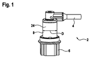
図1は、第1の接続部4および第2の接続部6を有する差込コネクタ2を示し、これらの接続部は、管8によって互いに連結され、互いに直角に配置されている。内部を液体が流れるホースが、ラインシステムの第1の接続部4にそれ自体周知の方法で接続される。ラインシステムまたはユニット(例えば、ポンプなど)または液体タンクの別のホースを、第2の接続部6に接続することができる。第1の接続部4を第2の接続部6に連結する管8は、断面が円形の円筒管としてデザインされている。 FIG. 1 shows a plug-in connector 2 having a first connection 4 and a second connection 6, which are connected to one another by a tube 8 and arranged at right angles to one another. A hose through which liquid flows is connected to the first connection 4 of the line system in a manner known per se. A line system or unit (such as a pump) or another hose of the liquid tank can be connected to the second connection 6. The tube 8 that connects the first connecting portion 4 to the second connecting portion 6 is designed as a cylindrical tube having a circular cross section.
図2は、電気加熱要素が差し込まれる締付リング10を示している。締付リング10は、間隙12および4つの電気接続部14、16、18、および20を有する。締付リング10のクリア直径dは、管8の外径Dにほぼ一致している(図1を参照;0.95D≦d≦D)。
FIG. 2 shows a clamping
図3は、差込コネクタ2および加熱要素が差し込まれる締付リング10からなるホース接続装置を示している。図3では、2つの接続部4、8は、管8の長手方向軸によって規定された、差込コネクタ2の長手方向に整列している。締付リング10が、管8に対して押圧される。そうするために、管8が締付リング10の間隙12をとおして押し込まれる。締付リング10は、管8に押しつけられ、締付リング10の間隙12が管8の長手方向に延在し、締付リング10が、管8を周方向にほぼ完全に取り囲み(間隙12の領域を除く)、かつ管8をその長手方向に少なくとも分部的に取り囲むような寸法に構成されている。締付リング10は、図3に示されているように好ましくは管8と同じ長さである。これにより、締付リング10がその全長にわたって前記管を取り囲む。締付リング10のクリア直径dが、管8の直径Dにほぼ一致しているため、装置が完成すると、締付リング10の内面22(図2を参照)が、管8の外面24(図1を参照)を圧迫する。これにより、加熱要素が差し込まれた締付リング10と差込コネクタ2の管8との間の十分な熱交換が保証される。上述の寸法構成により、締付リング10は、管8にさらに確実に固定されるため、追加の締付要素を用いなくても管8の所定の位置に確実に固定される。
FIG. 3 shows a hose connection device comprising a plug-in connector 2 and a
ピン電気接点26、28、30、および32が、ラインシステムの電気接続部14、16、18、および20(図2も参照)内に押し込まれる。この場合、ピン電気接点の2つが、締付リング10に差し込まれた加熱要素を電源に接続する役割を果たす。このために、他の2つの電気接続部が、別の2つのピン電気接点に接続され、このうちの第1のピン接点が加熱ワイヤの第1の端部に接続され、第2のピン接点が、加熱ワイヤの第2の端部に接続される。加熱ワイヤは、第1の接続部4に接続されたホースを加熱するために巻かれている(図3には不図示)。これは、ホースの電気加熱ワイヤを同様に、締付リング10に差し込まれた加熱要素を通して電源に接続する結果をもたらす。各ピン接点26、28、30、および32は、環状シリコーンシール34を備えている。環状シリコーンシール34は、各ピン接点26、28、30、および32が各スリーブ状電気接続部14、16、18、および20内に完全に押し込まれると、ピン接点が各スリーブ状電気接続部内に収容されるようにピン接点上に配設されている。同時に、シリコーンシールは、このシリコーンシールがスリーブ状電気接続部14、16、18、および20の内壁を圧迫し、かつスリーブ状電気接続部14、16、18、および20を外部から遮断する寸法に構成されている。
Pin
図4は、加熱要素36を斜視図で示している。加熱要素36は、第1の電気接続部14を有する第1の導電トラック38および第2の電気接続部18を有する第2の導電トラック40を有する。第1の導電トラック38および第2の導電トラック40は、互いに一定距離Aで配置され、電気加熱抵抗42および44によって互いに電気的に接続されている。この場合、距離Aは、完成した締付リング10における2つの導電トラックの互いの距離が、差込コネクタ2の管8の長さ(図1を参照)にほぼ一致するように選択される。これにより、管の全長にわたって均一な加熱が保証される。
FIG. 4 shows the
2つの導電トラック38、40は、スタンピングとしてデザインされ、それぞれは、加熱抵抗42、44用の位置決め要素46、48、50、および52を備えている。加熱抵抗42、44は、位置決め要素46、48、50、および52内にクリップ止めされている。導電トラック38、40は、最初に1回のスタンピングですべてが打ち抜くことができ、この時点ではまだブリッジによって互いに連結されている。このブリッジは、導電トラック38、40が加熱抵抗42、44によって互いに接続されるとすぐに除去される。
The two
既に述べた電気接続部14、16に加えて,第1の導電トラック38は、第3の電気接続部18を備え、第2の導電トラック40は、第4の電気接続部20を備えている。電気接続部14、16、18、および20は、スリーブ状デザインであり、金属からなる。電源用のピン接点が、完成したラインシステムの電気接続部14および16に取り付けられ(図3も参照)、ホースの加熱ワイヤ用のピン接点が、電気接続部18および20に取り付けられる(図3の説明も参照)。
In addition to the
図4に示されている加熱要素10は、流動性電気絶縁プラスチックによって完全に包囲され、その結果、図2に示されている締付リング10が形成される。これは、好ましくは、電気絶縁プラスチックを用いて射出成形によって達成される。この場合、加熱要素36は、導電トラック38および40が締付リングの周方向に延在するように、完成した締付リング10内に存在する。加熱抵抗42、44の長手方向軸およびスリーブ状電気接続部14、16、18、および20の長手方向軸は、従って、締付リング10の長手方向軸に対して平行に延在する(図2も参照)。図4に示されている加熱要素36が弾性変形可能であるということから、完成した締付リング10も、弾性変形可能であり、管8(図1および図3を参照)に単純に押しつけて、そこに固定することができる。
The
図5は、加熱要素36の別の実施形態を示している。加熱要素36は、電気絶縁フィルム54を備え、このフィルム上に第1の導電トラック38および第2の導電トラック40が配設されている。導電トラック38、40は、電気加熱抵抗42a〜42cによって互いに接続されている。各導電トラック38、40は、一端で直角に曲げられ、フィルム36を通ってこの方向に延出している。
FIG. 5 shows another embodiment of the
図6は、締付リング10を示し、この締付リング10の中には電気絶縁フィルム36が導入されている。締付リング10は、ポット状のデザインであり、フィルム36は、導電トラック36、40(図5を参照)が締付リング10の周方向に延在するように締付リング10のポット内に挿入されている。さらに、加熱抵抗42a、42b、および42cが、その長手方向軸が締付リング10の長手方向軸と平行に延在するように整列されている。導電トラックの2つの端部56、58は、紙の平面から突き出るように配置されている。導電トラックの2つの端部56、58は、2つの導電トラック38、40を電源に接続するために使用される。フィルム36が、締付リング10のポット内に導入されると、ポットとフィルムとの間の残りの空洞部は、電気絶縁注封材料60で完全に満たされる。図6に示されている締付リング10も、弾性変形可能なデザインであり、管8(図1および図3を参照)の周辺に単純に押しつけて、管8に固定することができる。
FIG. 6 shows the
2 差込コネクタ
4 第1の接続部
6 第2の接続部
8 管
10 締付リング
12 間隙
14 電気接続部
16 電気接続部
18 電気接続部
20 電気接続部
22 内面
24 外面
26 ピン電気接点
28 ピン電気接点
30 ピン電気接点
32 ピン電気接点
34 環状シール
36 加熱要素
38 導電トラック
40 導電トラック
42、42a、42b、42c 加熱抵抗
44 加熱抵抗
46 位置決め要素
48 位置決め要素
50 位置決め要素
52 位置決め要素
54 フィルム
56 導電トラックの端部
58 導電トラックの端部
60 注封材料
D 外径
d クリア直径
2 Plug-in Connector 4 First Connection 6 Second Connection 8
Claims (12)
前記差込コネクタ(2)が、少なくとも1つの第1の接続部(4)および少なくとも1つの第2の接続部(6)を備え、これらの接続部が、管(8)によって互いに接続されており、
前記管(8)の少なくとも一部分は、前記電気加熱要素(36)によって加熱することができ、
前記電気加熱要素(36)が、間隙(12)を備えた締付リング(10)内に差し込まれ、前記管(8)が、前記締付リング(10)が前記管(8)の少なくとも一部分を取り囲んで前記管(8)を圧迫するように、前記締付リング(10)の間隙(12)を通して押し込まれることを特徴とする、装置。 A hose connection device comprising a plug connector (2) and an electric heating element (36),
The plug-in connector (2) comprises at least one first connection (4) and at least one second connection (6), which are connected to each other by a tube (8). And
At least a portion of the tube (8) can be heated by the electric heating element (36);
The electric heating element (36) is inserted into a clamping ring (10) with a gap (12), the tube (8), the clamping ring (10) being at least part of the tube (8). The device is characterized in that it is pushed through the gap (12) of the clamping ring (10) so as to squeeze the tube (8).
Applications Claiming Priority (3)
| Application Number | Priority Date | Filing Date | Title |
|---|---|---|---|
| DE102009044404A DE102009044404A1 (en) | 2009-11-03 | 2009-11-03 | System for connecting hose lines |
| DE102009044404.1 | 2009-11-03 | ||
| PCT/EP2010/063269 WO2011054566A1 (en) | 2009-11-03 | 2010-09-10 | System for connecting hose lines |
Publications (2)
| Publication Number | Publication Date |
|---|---|
| JP2013510269A true JP2013510269A (en) | 2013-03-21 |
| JP2013510269A5 JP2013510269A5 (en) | 2013-07-25 |
Family
ID=43333214
Family Applications (1)
| Application Number | Title | Priority Date | Filing Date |
|---|---|---|---|
| JP2012535709A Pending JP2013510269A (en) | 2009-11-03 | 2010-09-10 | Hose connection device |
Country Status (6)
| Country | Link |
|---|---|
| US (1) | US8870229B2 (en) |
| EP (1) | EP2496874B1 (en) |
| JP (1) | JP2013510269A (en) |
| BR (1) | BR112012010457B1 (en) |
| DE (1) | DE102009044404A1 (en) |
| WO (1) | WO2011054566A1 (en) |
Cited By (1)
| Publication number | Priority date | Publication date | Assignee | Title |
|---|---|---|---|---|
| KR20180110622A (en) * | 2017-03-29 | 2018-10-10 | 테이 아우토모티브 (풀다프뤼크) 게엠베하 | Pipeline comprising a connector as well as a method for operating said pipeline |
Families Citing this family (5)
| Publication number | Priority date | Publication date | Assignee | Title |
|---|---|---|---|---|
| FR2984256B1 (en) * | 2011-12-19 | 2016-09-02 | Valeo Systemes Dessuyage | PLASTIC AND THERMOCONDUCTIVE COMPONENT OF A SYSTEM FOR THE SUPPLY AND / OR DISTRIBUTION OF ICE WASTE LIQUID OF A MOTOR VEHICLE |
| FR3003219B1 (en) * | 2013-03-14 | 2016-11-18 | Valeo Systemes Dessuyage | DEVICE FOR DISPENSING WINDSCREEN ICE WIPER BLINK FOR MOTOR VEHICLE WIPER |
| IT201700094931A1 (en) * | 2017-08-22 | 2019-02-22 | Hutchinson Srl | CONNECTOR FOR A DUCT FOR A HEATING FLUID, IN PARTICULAR OF A SCR SYSTEM OR A WATER INJECTION SYSTEM |
| DE102017223205A1 (en) | 2017-12-19 | 2019-06-19 | Contitech Schlauch Gmbh | Connecting arrangement for fluid lines |
| CN110497169B (en) * | 2019-07-31 | 2020-12-01 | 中国航发南方工业有限公司 | Method for decomposing cold end unit body |
Citations (3)
| Publication number | Priority date | Publication date | Assignee | Title |
|---|---|---|---|---|
| JPH11144843A (en) * | 1997-11-05 | 1999-05-28 | Ushio Inc | Heater |
| WO2008033927A2 (en) * | 2006-09-13 | 2008-03-20 | Watlow Electric Manufacturing Company | Modular heater systems |
| JP2009041619A (en) * | 2007-08-07 | 2009-02-26 | Yasutane Takato | Pipe heating/heat-insulation device |
Family Cites Families (21)
| Publication number | Priority date | Publication date | Assignee | Title |
|---|---|---|---|---|
| US1674488A (en) * | 1922-12-20 | 1928-06-19 | Gen Electric | Electric heating unit |
| US1864666A (en) * | 1930-04-04 | 1932-06-28 | John F Osborne | Electric mold |
| US2470854A (en) * | 1946-08-10 | 1949-05-24 | Michael L Kovac | Heating tool |
| US3519023A (en) * | 1968-08-05 | 1970-07-07 | Ora W Burns Sr | Defrosting collar for pipes |
| JPS5541646A (en) * | 1978-09-18 | 1980-03-24 | Shinetsu Polymer Co | Hollow tubular heater |
| SE7904310L (en) * | 1979-05-16 | 1980-11-17 | Bulten Kanthal Ab | ELECTRICAL ELEMENT |
| US4629216A (en) * | 1982-06-29 | 1986-12-16 | I. C. Moller A/S | Method of joining prefabricated heat insulated pipes and a welding fitting therefore |
| DE3544589C2 (en) * | 1985-12-17 | 1994-01-13 | Wolf Woco & Co Franz J | Heated element of a windscreen washer system for motor vehicles |
| DE3911633A1 (en) * | 1989-04-10 | 1990-10-11 | Armin Dommer | HEATING DEVICE FOR A WELDING DEVICE |
| EP0483621B1 (en) * | 1990-11-02 | 1997-01-08 | Watlow Electric Manufacturing Company | Heater assembly, especially in form of a band or strip |
| CH685403A5 (en) * | 1991-07-22 | 1995-06-30 | Fischer Georg Rohrleitung | Molding of thermoplastic material. |
| US5714738A (en) * | 1995-07-10 | 1998-02-03 | Watlow Electric Manufacturing Co. | Apparatus and methods of making and using heater apparatus for heating an object having two-dimensional or three-dimensional curvature |
| US5667712A (en) * | 1996-02-16 | 1997-09-16 | Watlow Electric Manufacturing Company | Expandable multi-segment band heater construction with improved electrical connection |
| JPH11159685A (en) * | 1997-12-01 | 1999-06-15 | Suzuki Shoukan:Kk | Piping heater |
| US6608968B2 (en) * | 2001-11-23 | 2003-08-19 | Allan P Bakke | Convection blood warming system with disposable flattened tube envelope incorporating paperboard “needle” for inserting envelope between heating plates and employing active and passive insulation of outlet flow path to provide normothermic fluid at zero to 600 milliliters per minute |
| DE102005050867A1 (en) | 2005-10-24 | 2007-04-26 | Dbk David + Baader Gmbh | Heatable connector |
| DE102007016789B4 (en) * | 2007-04-05 | 2022-02-10 | Eichenauer Heizelemente Gmbh & Co. Kg | Heated connection piece for a fluid line |
| PL2363627T3 (en) | 2007-04-26 | 2018-10-31 | Voss Automotive Gmbh | Circuit connector for fluid transfers |
| DE102008016175A1 (en) * | 2007-10-31 | 2009-05-14 | Barkey, Volker | Device for controlling the temperature of a fluid line comprises a encased line formed by a thermally conducting polymer layer in which is embedded a heating element |
| WO2009080501A1 (en) * | 2007-12-21 | 2009-07-02 | Voss Automotive Gmbh | Line connector for media lines and ready-made media line with at least one such line connector |
| DE202008015289U1 (en) | 2008-11-18 | 2010-04-08 | Voss Automotive Gmbh | Cable connector for media cables |
-
2009
- 2009-11-03 DE DE102009044404A patent/DE102009044404A1/en not_active Withdrawn
-
2010
- 2010-09-10 BR BR112012010457A patent/BR112012010457B1/en active IP Right Grant
- 2010-09-10 JP JP2012535709A patent/JP2013510269A/en active Pending
- 2010-09-10 WO PCT/EP2010/063269 patent/WO2011054566A1/en active Application Filing
- 2010-09-10 EP EP10770739.0A patent/EP2496874B1/en active Active
-
2012
- 2012-05-02 US US13/462,264 patent/US8870229B2/en active Active
Patent Citations (4)
| Publication number | Priority date | Publication date | Assignee | Title |
|---|---|---|---|---|
| JPH11144843A (en) * | 1997-11-05 | 1999-05-28 | Ushio Inc | Heater |
| WO2008033927A2 (en) * | 2006-09-13 | 2008-03-20 | Watlow Electric Manufacturing Company | Modular heater systems |
| JP2010503966A (en) * | 2006-09-13 | 2010-02-04 | ワトロウ エレクトリック マニュファクチュアリング カンパニー | Modular heater system |
| JP2009041619A (en) * | 2007-08-07 | 2009-02-26 | Yasutane Takato | Pipe heating/heat-insulation device |
Cited By (3)
| Publication number | Priority date | Publication date | Assignee | Title |
|---|---|---|---|---|
| KR20180110622A (en) * | 2017-03-29 | 2018-10-10 | 테이 아우토모티브 (풀다프뤼크) 게엠베하 | Pipeline comprising a connector as well as a method for operating said pipeline |
| JP2018169045A (en) * | 2017-03-29 | 2018-11-01 | テーイー オートモーティブ(フルダブリュック) ゲゼルシャフト ミット ベシュレンクテル ハフツング | Piping system including connector and method of operating the piping system |
| KR102429702B1 (en) * | 2017-03-29 | 2022-08-05 | 테이 아우토모티브 (풀다프뤼크) 게엠베하 | Pipeline comprising a connector as well as a method for operating said pipeline |
Also Published As
| Publication number | Publication date |
|---|---|
| WO2011054566A1 (en) | 2011-05-12 |
| EP2496874B1 (en) | 2018-08-01 |
| BR112012010457B1 (en) | 2020-01-28 |
| US8870229B2 (en) | 2014-10-28 |
| US20120255163A1 (en) | 2012-10-11 |
| DE102009044404A1 (en) | 2011-05-05 |
| BR112012010457A2 (en) | 2016-03-08 |
| EP2496874A1 (en) | 2012-09-12 |
Similar Documents
| Publication | Publication Date | Title |
|---|---|---|
| FI85412C (en) | FOERBINDNINGSSTYCKE FOER UPPHETTNINGSBARA SLANGAR. | |
| US9890889B2 (en) | Line connector and ready-made media line | |
| JP2013510269A (en) | Hose connection device | |
| US5791377A (en) | Electrically heated conduit | |
| JP6000271B2 (en) | A ready-made medium line that can be heated electrically and a method of manufacturing the medium line | |
| US7857645B2 (en) | Connector arrangement for a medium-conducting, electrically-heatable hose | |
| US8591241B2 (en) | Electrically heatable media line and line connector | |
| JP7008137B2 (en) | Self-piercing connector | |
| JP5745806B2 (en) | Equipment for heating fluid transport piping | |
| US9791086B2 (en) | At least partially heatable line-connector for a heatable media line, and an assembled media line comprising such a line-connector | |
| JP6764275B2 (en) | Heating connector assembly | |
| WO2017010240A1 (en) | Molding-equipped electric wire and molding-equipped electric wire production method | |
| US9366454B2 (en) | Heatable connection apparatus including media-conducting, electrically heatable hoses | |
| US20080202108A1 (en) | Reductant supply system for a waste gas cleaning catalyst of an internal combustion engine and a plug-in connection for connecting heatable fluid ducts | |
| CN108700242B (en) | Connector comprising an assembly aid and method for manufacturing said connector | |
| CN108692122B (en) | Pipe comprising a connector and method for operating said pipe | |
| EP3901598A1 (en) | Temperature sensor for rotating electric machine and method of manufacturing the same | |
| TWI702884B (en) | Compact robust connector assembly for high voltage electrical heaters | |
| US20110168135A1 (en) | Sealed wire interface | |
| US11168598B2 (en) | Heated tubing with plug, and a method for operating this tubing | |
| US20150270029A1 (en) | Waterproofing structure for insulation-coated electrical wire, and wire harness | |
| JP2002544652A (en) | How to protect cable strands | |
| JP5472117B2 (en) | Heated media conduit unit | |
| CN204104153U (en) | Electric heating tube component | |
| KR20000004357U (en) | Car temperature sensor |
Legal Events
| Date | Code | Title | Description |
|---|---|---|---|
| A521 | Request for written amendment filed |
Free format text: JAPANESE INTERMEDIATE CODE: A523 Effective date: 20130607 |
|
| A621 | Written request for application examination |
Free format text: JAPANESE INTERMEDIATE CODE: A621 Effective date: 20130607 |
|
| A977 | Report on retrieval |
Free format text: JAPANESE INTERMEDIATE CODE: A971007 Effective date: 20140311 |
|
| A131 | Notification of reasons for refusal |
Free format text: JAPANESE INTERMEDIATE CODE: A131 Effective date: 20140408 |
|
| A02 | Decision of refusal |
Free format text: JAPANESE INTERMEDIATE CODE: A02 Effective date: 20141112 |