JP2013506969A - Energy storage unit with extended life - Google Patents
Energy storage unit with extended life Download PDFInfo
- Publication number
- JP2013506969A JP2013506969A JP2012532480A JP2012532480A JP2013506969A JP 2013506969 A JP2013506969 A JP 2013506969A JP 2012532480 A JP2012532480 A JP 2012532480A JP 2012532480 A JP2012532480 A JP 2012532480A JP 2013506969 A JP2013506969 A JP 2013506969A
- Authority
- JP
- Japan
- Prior art keywords
- fluid
- battery
- galvanic
- galvanic cell
- heat transfer
- Prior art date
- Legal status (The legal status is an assumption and is not a legal conclusion. Google has not performed a legal analysis and makes no representation as to the accuracy of the status listed.)
- Pending
Links
Images


Classifications
-
- H—ELECTRICITY
- H01—ELECTRIC ELEMENTS
- H01M—PROCESSES OR MEANS, e.g. BATTERIES, FOR THE DIRECT CONVERSION OF CHEMICAL ENERGY INTO ELECTRICAL ENERGY
- H01M10/00—Secondary cells; Manufacture thereof
- H01M10/60—Heating or cooling; Temperature control
- H01M10/65—Means for temperature control structurally associated with the cells
- H01M10/655—Solid structures for heat exchange or heat conduction
- H01M10/6556—Solid parts with flow channel passages or pipes for heat exchange
- H01M10/6557—Solid parts with flow channel passages or pipes for heat exchange arranged between the cells
-
- H—ELECTRICITY
- H01—ELECTRIC ELEMENTS
- H01M—PROCESSES OR MEANS, e.g. BATTERIES, FOR THE DIRECT CONVERSION OF CHEMICAL ENERGY INTO ELECTRICAL ENERGY
- H01M10/00—Secondary cells; Manufacture thereof
- H01M10/42—Methods or arrangements for servicing or maintenance of secondary cells or secondary half-cells
- H01M10/48—Accumulators combined with arrangements for measuring, testing or indicating the condition of cells, e.g. the level or density of the electrolyte
- H01M10/482—Accumulators combined with arrangements for measuring, testing or indicating the condition of cells, e.g. the level or density of the electrolyte for several batteries or cells simultaneously or sequentially
-
- H—ELECTRICITY
- H01—ELECTRIC ELEMENTS
- H01M—PROCESSES OR MEANS, e.g. BATTERIES, FOR THE DIRECT CONVERSION OF CHEMICAL ENERGY INTO ELECTRICAL ENERGY
- H01M10/00—Secondary cells; Manufacture thereof
- H01M10/42—Methods or arrangements for servicing or maintenance of secondary cells or secondary half-cells
- H01M10/48—Accumulators combined with arrangements for measuring, testing or indicating the condition of cells, e.g. the level or density of the electrolyte
- H01M10/486—Accumulators combined with arrangements for measuring, testing or indicating the condition of cells, e.g. the level or density of the electrolyte for measuring temperature
-
- H—ELECTRICITY
- H01—ELECTRIC ELEMENTS
- H01M—PROCESSES OR MEANS, e.g. BATTERIES, FOR THE DIRECT CONVERSION OF CHEMICAL ENERGY INTO ELECTRICAL ENERGY
- H01M10/00—Secondary cells; Manufacture thereof
- H01M10/60—Heating or cooling; Temperature control
- H01M10/61—Types of temperature control
- H01M10/613—Cooling or keeping cold
-
- H—ELECTRICITY
- H01—ELECTRIC ELEMENTS
- H01M—PROCESSES OR MEANS, e.g. BATTERIES, FOR THE DIRECT CONVERSION OF CHEMICAL ENERGY INTO ELECTRICAL ENERGY
- H01M10/00—Secondary cells; Manufacture thereof
- H01M10/60—Heating or cooling; Temperature control
- H01M10/62—Heating or cooling; Temperature control specially adapted for specific applications
- H01M10/625—Vehicles
-
- H—ELECTRICITY
- H01—ELECTRIC ELEMENTS
- H01M—PROCESSES OR MEANS, e.g. BATTERIES, FOR THE DIRECT CONVERSION OF CHEMICAL ENERGY INTO ELECTRICAL ENERGY
- H01M10/00—Secondary cells; Manufacture thereof
- H01M10/60—Heating or cooling; Temperature control
- H01M10/63—Control systems
-
- H—ELECTRICITY
- H01—ELECTRIC ELEMENTS
- H01M—PROCESSES OR MEANS, e.g. BATTERIES, FOR THE DIRECT CONVERSION OF CHEMICAL ENERGY INTO ELECTRICAL ENERGY
- H01M10/00—Secondary cells; Manufacture thereof
- H01M10/60—Heating or cooling; Temperature control
- H01M10/64—Heating or cooling; Temperature control characterised by the shape of the cells
- H01M10/647—Prismatic or flat cells, e.g. pouch cells
-
- H—ELECTRICITY
- H01—ELECTRIC ELEMENTS
- H01M—PROCESSES OR MEANS, e.g. BATTERIES, FOR THE DIRECT CONVERSION OF CHEMICAL ENERGY INTO ELECTRICAL ENERGY
- H01M10/00—Secondary cells; Manufacture thereof
- H01M10/60—Heating or cooling; Temperature control
- H01M10/65—Means for temperature control structurally associated with the cells
- H01M10/651—Means for temperature control structurally associated with the cells characterised by parameters specified by a numeric value or mathematical formula, e.g. ratios, sizes or concentrations
-
- H—ELECTRICITY
- H01—ELECTRIC ELEMENTS
- H01M—PROCESSES OR MEANS, e.g. BATTERIES, FOR THE DIRECT CONVERSION OF CHEMICAL ENERGY INTO ELECTRICAL ENERGY
- H01M10/00—Secondary cells; Manufacture thereof
- H01M10/60—Heating or cooling; Temperature control
- H01M10/65—Means for temperature control structurally associated with the cells
- H01M10/656—Means for temperature control structurally associated with the cells characterised by the type of heat-exchange fluid
- H01M10/6561—Gases
- H01M10/6563—Gases with forced flow, e.g. by blowers
-
- H—ELECTRICITY
- H01—ELECTRIC ELEMENTS
- H01M—PROCESSES OR MEANS, e.g. BATTERIES, FOR THE DIRECT CONVERSION OF CHEMICAL ENERGY INTO ELECTRICAL ENERGY
- H01M50/00—Constructional details or processes of manufacture of the non-active parts of electrochemical cells other than fuel cells, e.g. hybrid cells
- H01M50/20—Mountings; Secondary casings or frames; Racks, modules or packs; Suspension devices; Shock absorbers; Transport or carrying devices; Holders
- H01M50/233—Mountings; Secondary casings or frames; Racks, modules or packs; Suspension devices; Shock absorbers; Transport or carrying devices; Holders characterised by physical properties of casings or racks, e.g. dimensions
- H01M50/24—Mountings; Secondary casings or frames; Racks, modules or packs; Suspension devices; Shock absorbers; Transport or carrying devices; Holders characterised by physical properties of casings or racks, e.g. dimensions adapted for protecting batteries from their environment, e.g. from corrosion
-
- H—ELECTRICITY
- H01—ELECTRIC ELEMENTS
- H01M—PROCESSES OR MEANS, e.g. BATTERIES, FOR THE DIRECT CONVERSION OF CHEMICAL ENERGY INTO ELECTRICAL ENERGY
- H01M50/00—Constructional details or processes of manufacture of the non-active parts of electrochemical cells other than fuel cells, e.g. hybrid cells
- H01M50/20—Mountings; Secondary casings or frames; Racks, modules or packs; Suspension devices; Shock absorbers; Transport or carrying devices; Holders
- H01M50/258—Modular batteries; Casings provided with means for assembling
-
- H—ELECTRICITY
- H01—ELECTRIC ELEMENTS
- H01M—PROCESSES OR MEANS, e.g. BATTERIES, FOR THE DIRECT CONVERSION OF CHEMICAL ENERGY INTO ELECTRICAL ENERGY
- H01M50/00—Constructional details or processes of manufacture of the non-active parts of electrochemical cells other than fuel cells, e.g. hybrid cells
- H01M50/40—Separators; Membranes; Diaphragms; Spacing elements inside cells
- H01M50/409—Separators, membranes or diaphragms characterised by the material
- H01M50/443—Particulate material
-
- Y—GENERAL TAGGING OF NEW TECHNOLOGICAL DEVELOPMENTS; GENERAL TAGGING OF CROSS-SECTIONAL TECHNOLOGIES SPANNING OVER SEVERAL SECTIONS OF THE IPC; TECHNICAL SUBJECTS COVERED BY FORMER USPC CROSS-REFERENCE ART COLLECTIONS [XRACs] AND DIGESTS
- Y02—TECHNOLOGIES OR APPLICATIONS FOR MITIGATION OR ADAPTATION AGAINST CLIMATE CHANGE
- Y02E—REDUCTION OF GREENHOUSE GAS [GHG] EMISSIONS, RELATED TO ENERGY GENERATION, TRANSMISSION OR DISTRIBUTION
- Y02E60/00—Enabling technologies; Technologies with a potential or indirect contribution to GHG emissions mitigation
- Y02E60/10—Energy storage using batteries
-
- Y—GENERAL TAGGING OF NEW TECHNOLOGICAL DEVELOPMENTS; GENERAL TAGGING OF CROSS-SECTIONAL TECHNOLOGIES SPANNING OVER SEVERAL SECTIONS OF THE IPC; TECHNICAL SUBJECTS COVERED BY FORMER USPC CROSS-REFERENCE ART COLLECTIONS [XRACs] AND DIGESTS
- Y02—TECHNOLOGIES OR APPLICATIONS FOR MITIGATION OR ADAPTATION AGAINST CLIMATE CHANGE
- Y02P—CLIMATE CHANGE MITIGATION TECHNOLOGIES IN THE PRODUCTION OR PROCESSING OF GOODS
- Y02P70/00—Climate change mitigation technologies in the production process for final industrial or consumer products
- Y02P70/50—Manufacturing or production processes characterised by the final manufactured product
-
- Y—GENERAL TAGGING OF NEW TECHNOLOGICAL DEVELOPMENTS; GENERAL TAGGING OF CROSS-SECTIONAL TECHNOLOGIES SPANNING OVER SEVERAL SECTIONS OF THE IPC; TECHNICAL SUBJECTS COVERED BY FORMER USPC CROSS-REFERENCE ART COLLECTIONS [XRACs] AND DIGESTS
- Y10—TECHNICAL SUBJECTS COVERED BY FORMER USPC
- Y10T—TECHNICAL SUBJECTS COVERED BY FORMER US CLASSIFICATION
- Y10T29/00—Metal working
- Y10T29/49—Method of mechanical manufacture
- Y10T29/49815—Disassembling
- Y10T29/49817—Disassembling with other than ancillary treating or assembling
Abstract
本発明に係る電気エネルギーを蓄積するための装置は、少なくとも1個のガルバニ電池を有している。また、本発明に係る装置は、少なくとも1個の内部空間を備え、上記少なくとも1個のガルバニ電池を少なくとも部分的に受容するために設けられている少なくとも1個の電池保持手段を有している。また、本発明に係る装置は、上記電池保持手段の上記内部空間を少なくとも部分的に取り囲み、上記少なくとも1個のガルバニ電池と少なくとも部分的に作用的に結合している少なくとも1個の第1の壁要素を有している。また、本発明に係る装置は、上記少なくとも1個の第1の壁要素と作用的に結合している少なくとも1個の伝熱手段を有している。また、本発明に係る装置は、上記伝熱手段に付設され、第1の流体を貫流させるために設けられている少なくとも1本の流体通路を有している。本発明に係る装置は、膨張するように設けられた少なくとも1個の位置補正手段を有し、少なくともこの位置補正手段が少なくとも部分的に上記電池保持手段の内部に配置されていることを特徴としている。The device for storing electrical energy according to the present invention has at least one galvanic cell. The apparatus according to the present invention further comprises at least one battery holding means provided to receive at least part of the at least one galvanic battery, comprising at least one internal space. . The apparatus according to the present invention at least partially surrounds the internal space of the battery holding means and is at least partially operatively coupled to the at least one galvanic battery. Has wall elements. The device according to the invention also comprises at least one heat transfer means operatively coupled to the at least one first wall element. The apparatus according to the present invention has at least one fluid passage attached to the heat transfer means and provided for allowing the first fluid to flow therethrough. The apparatus according to the present invention has at least one position correcting means provided so as to expand, and at least the position correcting means is at least partially disposed inside the battery holding means. Yes.
Description
本発明は、一般的にはエネルギー蓄積ユニットに関するものである。自動車の駆動部に給電を行うための再充電可能なリチウム・イオンバッテリーとの関連で本発明を説明する。しかし、本発明はガルバニ電池の構成、その化学的態様に関係なく、また給電される駆動部の種類にも関係なく適用できる。 The present invention relates generally to energy storage units. The present invention will be described in the context of a rechargeable lithium-ion battery for powering an automobile drive. However, the present invention can be applied regardless of the configuration of the galvanic cell and its chemical form, and regardless of the type of the drive unit to be fed.
自動車の駆動部に給電を行うために複数個のガルバニ電池を備えた再充電可能なバッテリーが、従来技術により知られている。この種のバッテリーの作動中に、ガルバニ電池内に非可逆性の化学反応も発生する。この反応がガルバニ電池の充電容量を次第に低減させることもある。 Rechargeable batteries comprising a plurality of galvanic cells for supplying power to the drive of an automobile are known from the prior art. During operation of this type of battery, irreversible chemical reactions also occur in the galvanic cell. This reaction may gradually reduce the charge capacity of the galvanic cell.
本発明の課題は、充電サイクル数を増加させてもバッテリーのガルバニ電池の充電容量を維持することである。 An object of the present invention is to maintain the charge capacity of a galvanic cell of a battery even when the number of charge cycles is increased.
この課題は、本発明によれば、独立請求項の対象によって解決される。本発明の他の有利な構成は、従属項の対象である。 This problem is solved according to the invention by the subject matter of the independent claims. Other advantageous configurations of the invention are the subject of the dependent claims.
本発明による電気エネルギー蓄積装置は、少なくとも1個のガルバニ電池を有している。本発明に係る装置は、さらに、少なくとも1個の内部空間を備えた少なくとも1個の電池保持手段/電池保持器を有し、この電池保持器は少なくとも1個のガルバニ電池を少なくとも部分的に受容するために設けられている。本発明に係る装置は、さらに、少なくとも1個の第1の壁要素を有し、この第1の壁要素は、電池保持器の内部空間を少なくとも部分的に取り囲み、且つ少なくとも1個のガルバニ電池と少なくとも部分的に作用的に結合している。本発明に係る装置は、さらに、少なくとも1個の伝熱手段を有し、この伝熱手段は少なくとも1個の第1の壁要素と作用的に結合している。本発明に係る装置は、さらに、少なくとも1本の流体通路を有し、この流体通路は伝熱手段に連結されて、第1の流体を貫流させるために設けられている。本発明に係る装置は、膨張するように構成された少なくとも1個の位置補正手段を有し、少なくともこの位置補正手段は少なくとも部分的に電池保持器の内部に配置されていることを特徴としている。 The electrical energy storage device according to the present invention has at least one galvanic cell. The device according to the invention further comprises at least one battery holding means / battery holder with at least one internal space, the battery holder at least partially receiving at least one galvanic battery. Is provided to do. The device according to the invention further comprises at least one first wall element, which at least partly surrounds the interior space of the battery holder and at least one galvanic cell. And at least partially operatively coupled. The device according to the invention further comprises at least one heat transfer means, which heat transfer means is operatively coupled to at least one first wall element. The apparatus according to the present invention further comprises at least one fluid passage, which is connected to the heat transfer means and is provided for allowing the first fluid to flow through. The device according to the invention has at least one position correction means configured to expand, and is characterized in that at least this position correction means is at least partly arranged inside the battery holder. .
本発明でいうガルバニ電池とは、化学エネルギーの蓄積及び電気エネルギーの放出にも用いられる機構である。ガルバニ電池は、充電の際に電気エネルギーを化学エネルギーに変換して蓄積するように構成することもできる。これは二次電池又はアキュムレータとして知られている。本発明でいう伝熱手段とは、ガルバニ電池と比較してより高い伝熱性をも有する装置である。特に伝熱手段は、作用的に結合しているガルバニ電池に熱エネルギーを供給する。これは特に周囲温度が低い場合に望ましく、ガルバニ電池が事前にエージングするのを防止して、その効率を向上させる。また、伝熱手段は作用的に結合しているガルバニ電池から熱エネルギーを放出させ、これによってガルバニ電池の損傷が特に防止されて、その寿命が長くなる。特に高い充電電流及び/又は放電電流を伴う充電サイクル中及び/又は放電サイクル中にガルバニ電池が加熱され、その際にガルバニ電池の温度が高くなりすぎるとその寿命が短くなり、及び/又は、ガルバニ電池が破損する。 The galvanic cell referred to in the present invention is a mechanism used for storing chemical energy and discharging electric energy. Galvanic cells can also be configured to convert electrical energy into chemical energy and store it during charging. This is known as a secondary battery or accumulator. The heat transfer means referred to in the present invention is a device having higher heat transfer property than a galvanic cell. In particular, the heat transfer means supplies thermal energy to the galvanic cells that are operatively coupled. This is particularly desirable when the ambient temperature is low, preventing the galvanic cell from pre-aging and improving its efficiency. The heat transfer means also releases thermal energy from the galvanic cells that are operatively coupled, thereby preventing damage to the galvanic cells and extending their life. In particular, if a galvanic cell is heated during a charge cycle and / or during a discharge cycle with a high charge current and / or discharge current, if the temperature of the galvanic cell becomes too high, its life is shortened and / or galvanic. The battery is damaged.
本発明でいう流体とは、任意の小さな剪断応力に対して実質的に抵抗しない物質である。その意味では気体と液体が流体である。 As used herein, fluid is a substance that does not substantially resist any small shear stress. In that sense, gas and liquid are fluids.
本発明でいう流体通路とは、この流体通路が閉じた空間として構成されている限りにおいては、少なくとも第1の流体を受容して誘導し、又は少なくともこの第1の流体を保持することができる装置である。この流体通路は、好ましくは、第2の流体をも受容して誘導又は保持するために設けられている。好ましくは、流体通路は少なくとも第1の流体のために、少なくとも1個の入口領域と少なくとも1個の出口領域とを有し、この少なくとも第1の流体は、好ましくは通路を少なくとも上記入口領域から少なくとも上記出口領域へと貫流する。好ましくは、少なくとも第1の流体は、流体通路の内部空間、及び/又は流体通路壁、及び/又は流体通路と作用的に結合している少なくとも1個の装置よりも低いか高い温度を有している。少なくとも第1の流体は、支配的な温度に依存して加熱又は冷却され、これによって熱エネルギーが、流体通路の内部空間、及び/又は流体通路壁、及び/又は流体通路と作用的に結合している少なくとも1個の装置から排出され、又はこれに供給される。 As long as this fluid passage is configured as a closed space, the fluid passage referred to in the present invention can receive and guide at least the first fluid, or at least hold the first fluid. Device. This fluid passage is preferably provided for receiving and guiding or holding the second fluid as well. Preferably, the fluid passage has at least one inlet region and at least one outlet region for at least the first fluid, and the at least first fluid preferably passes the passage from at least the inlet region. It flows at least into the exit area. Preferably, at least the first fluid has a lower or higher temperature than the interior space of the fluid passage and / or the fluid passage wall and / or at least one device operatively associated with the fluid passage. ing. At least the first fluid is heated or cooled depending on the dominant temperature so that thermal energy is operatively coupled to the interior space of the fluid passage and / or the fluid passage wall and / or the fluid passage. Is discharged from or supplied to at least one device.
本発明でいう電池保持手段/電池保持器とは、内部空間と、この内部空間を少なくとも部分的に取り囲んでいる少なくとも1個の第1の壁要素とを有する装置である。壁要素は上記内部空間を完全に取り囲むように設けられてはいない。内部空間は、少なくとも1個のガルバニ電池を少なくとも部分的に受容するように構成されている。好ましくは、内部空間は、少なくとも1個のガルバニ電池に加えて、特に測定器、制御装置、少なくとも1個の位置補正手段のような他の機構を受容するように構成されている。少なくとも1個の受容されるガルバニ電池と少なくとも受容される他の機構とは、好ましくは、この電池保持手段によって圧力嵌合手段により、及び/又は熱を誘導するように取り囲まれている。好ましくは、少なくとも1個のガルバニ電池は、添設される電池ケースの少なくとも1個の第1の外面が少なくとも部分的に、少なくとも第1の壁要素と固体間面接触を形成するように、電池保持器によって取り囲まれている。この配置の場合、ガルバニ電池から放出されるべき熱エネルギーが、更なる固体間接触なしに、ダイレクトに電池保持器の上記外面に誘導されるのが有利である。電池保持器の少なくとも第1の壁要素は、高伝熱性の金属材料から成るのが好ましく、特に好ましくはアルミニウムから成っている。 The battery holding means / battery holder referred to in the present invention is an apparatus having an internal space and at least one first wall element that at least partially surrounds the internal space. The wall element is not provided so as to completely surround the interior space. The internal space is configured to at least partially receive at least one galvanic cell. Preferably, the internal space is configured to receive in addition to at least one galvanic cell, in particular other mechanisms such as a measuring device, a control device, and at least one position correction means. The at least one received galvanic cell and at least the other received mechanism are preferably surrounded by the pressure retaining means and / or to induce heat by the battery holding means. Preferably, the at least one galvanic cell is such that the at least one first outer surface of the attached battery case is at least partially in at least partial contact with at least the first wall element. Surrounded by a cage. In this arrangement, it is advantageous that the thermal energy to be released from the galvanic cell is directly guided to the outer surface of the cell holder without further solid-solid contact. At least the first wall element of the battery holder is preferably made of a highly heat-conducting metallic material, particularly preferably aluminum.
本発明でいう位置補正手段とは、好ましくは温度に基づいて、及び/又はこの位置補正手段に作用する周囲圧力に基づいて、優先方向に膨張するように設けられている装置であり、その力は第1の壁要素の方向において、少なくともガルバニ電池にも作用する。位置補正手段は、特に、少なくとも1個の電池保持器内部で、圧力嵌合により、少なくとも1個のガルバニ電池と作用的に結合するように設けられる。 The position correction means in the present invention is a device provided to expand in a preferred direction, preferably on the basis of temperature and / or on the basis of the ambient pressure acting on this position correction means. Also acts at least on the galvanic cell in the direction of the first wall element. The position correction means is provided in particular to be operatively coupled to at least one galvanic cell by pressure fitting within at least one battery holder.
少なくともこの位置補正手段に作用する力の種類及び/又は大きさは、実質的にその温度及びこの位置補正手段に作用する周囲圧力に依存しているのが好ましい。好ましくは、少なくともこの位置補正手段に作用する力の種類及び/又は大きさは、その幾何学的形態及び/又は製造する材料によって予め設定することができる。好ましくは、一定の周囲圧力に対して温度に依存して位置補正手段に作用する力は、少なくとも間欠的に、少なくとも1つの数学的関数によって表される。 At least the type and / or magnitude of the force acting on the position correction means preferably depends substantially on the temperature and the ambient pressure acting on the position correction means. Preferably, at least the type and / or magnitude of the force acting on this position correcting means can be preset by its geometrical form and / or the material to be manufactured. Preferably, the force acting on the position correction means as a function of temperature for a constant ambient pressure is represented at least intermittently by at least one mathematical function.
特にガルバニ電池の熱的負荷が高い場合には、熱エネルギー流の遮断又は妨害により、ガルバニ電池内部及び/又は電池保持器内部に熱のよどみが生じ、これによってこのガルバニ電池の作動温度が上昇する。特にこのガルバニ電池の作動温度が高ければ、寿命が短くなり、よって可能な充電サイクル数及び放電サイクル数も減少する。熱的負荷が非常に高ければ、リチウム・イオンアキュムレータ内でセパレータの溶融が生じ、リチウム・イオンアキュムレータを破壊する。さらに、特にリチウムと電解液との寄生反応によってリチウム・イオンアキュムレータの容量が経時的に減少する。その崩壊速度は温度が上昇するとともに増大する。 Particularly when the galvanic cell has a high thermal load, the thermal energy flow is interrupted or obstructed to cause stagnation of heat inside the galvanic cell and / or the battery holder, thereby increasing the operating temperature of the galvanic cell. . In particular, if the operating temperature of the galvanic cell is high, the lifetime is shortened, and thus the number of possible charge and discharge cycles is also reduced. If the thermal load is very high, the separator melts in the lithium ion accumulator and destroys the lithium ion accumulator. Furthermore, the capacity of the lithium ion accumulator decreases with time due to the parasitic reaction between lithium and the electrolyte. Its decay rate increases with increasing temperature.
好ましくは、充電サイクル時の少なくとも1個のガルバニ電池の容積増大は、少なくとも添設されている位置補正手段が対応的に容積減少することによって補正され、少なくとも1個のガルバニ電池及び/又は少なくとも電池保持手段の変形及び/又は破壊が阻止される。好ましくは、位置補正手段は少なくとも第1の壁要素に対する少なくとも1個のガルバニ電池の押圧力を調整し、好ましくは一定の値に調整する。 Preferably, the increase in the volume of the at least one galvanic cell during the charging cycle is corrected by a corresponding decrease in the volume of at least the attached position correction means, and the at least one galvanic cell and / or at least the battery is corrected. Deformation and / or destruction of the holding means is prevented. Preferably, the position correction means adjusts the pressing force of at least one galvanic cell against at least the first wall element, and preferably adjusts it to a constant value.
充電サイクル時及び/又は放電サイクル時に回避できない、組み込まれたガルバニ電池の容積変化は、この位置補正手段によって少なくとも部分的に補正される。少なくとも1個のガルバニ電池と第1の壁要素との間の熱接触は、位置補正手段によって改善され、及び/又は保証される。好ましくは、放電サイクル時の少なくとも1個のガルバニ電池の容積減少は、少なくとも添設される位置補正手段が対応的に容積増大することで補正され、少なくとも1個のガルバニ電池と少なくとも第1の壁要素との間の熱伝導性固体接触は、このケースでも得られる。特に、少なくとも第1の壁要素に対するガルバニ電池の押圧力が小さすぎると、少なくとも1個のガルバニ電池と少なくとも第1の壁要素との間での熱エネルギー流が遮断又は妨害される。好ましくは、位置補正手段は少なくとも第1の壁要素に対する少なくとも1個のガルバニ電池の押圧力を調整し、好ましくは一定値になるように調整する。このようにして上記課題が解決される。 The volume change of the incorporated galvanic cell, which cannot be avoided during the charge cycle and / or the discharge cycle, is at least partially corrected by this position correction means. Thermal contact between the at least one galvanic cell and the first wall element is improved and / or guaranteed by the position correction means. Preferably, the volume reduction of the at least one galvanic cell during the discharge cycle is corrected by a corresponding increase in the volume of at least the position correction means provided, and the at least one galvanic cell and at least the first wall are corrected. A thermally conductive solid contact between the elements is also obtained in this case. In particular, if the pressing force of the galvanic cell against at least the first wall element is too small, the thermal energy flow between the at least one galvanic cell and at least the first wall element is interrupted or obstructed. Preferably, the position correction means adjusts the pressing force of at least one galvanic cell against at least the first wall element, and preferably adjusts it to a constant value. In this way, the above problem is solved.
次に、本発明の他の有利な構成について説明する。 Next, another advantageous configuration of the present invention will be described.
本発明によれば、好ましくは、セパレータを使用する。セパレータは物質透過性の担持体から成り、部分的に物質透過性があること、すなわち少なくとも1個の材料に関しては実質的に透過性があり、少なくとも1個の他の材料に関しては実質的に非透過性であるのが好ましい。担持体は少なくとも1つの面が無機材料で被覆されている。物質透過性の担持体として、好ましくは有機材料を使用する。有機材料は好ましくは不織布として構成されている。有機材料、好ましくはポリマー、特に好ましくはポリエチレンテレフタラート(PET)が、イオン伝導性無機材料で被覆され、このイオン伝導性無機材料は、好ましくは−40℃ないし200℃の温度範囲でイオン伝導性を有する。イオン伝導性無機材料は、好ましくは、Zr、Al、Liのうちの少なくとも1つの元素を含む、リン酸塩、硫酸塩、チタン酸塩、ケイ酸塩、アルミノケイ酸塩からなるグループから選択された少なくとも1つの化合物であり、特に好ましくは酸化ジルコニウムである。イオン伝導性無機材料は、好ましくは100nm未満の最大径をもつ粒子を有している。このようなセパレータは、たとえばドイツのEvonik AG社から、商品名"Separion"で販売されている。 According to the invention, preferably a separator is used. The separator consists of a substance-permeable support and is partly permeable, i.e. substantially permeable for at least one material and substantially non-permeable for at least one other material. It is preferably permeable. The support has at least one surface coated with an inorganic material. An organic material is preferably used as the substance-permeable support. The organic material is preferably configured as a non-woven fabric. An organic material, preferably a polymer, particularly preferably polyethylene terephthalate (PET), is coated with an ion-conducting inorganic material, which is preferably ion-conducting in the temperature range of −40 ° C. to 200 ° C. Have The ion conductive inorganic material is preferably selected from the group consisting of phosphate, sulfate, titanate, silicate, aluminosilicate, comprising at least one element of Zr, Al, Li At least one compound, particularly preferably zirconium oxide. The ion conductive inorganic material preferably has particles having a maximum diameter of less than 100 nm. Such a separator is sold, for example, by Evonik AG, Germany, under the trade name “Separion”.
本発明でいう物体の縦軸線とは、物体の最大拡がりの方向に延在し、実質的に対称軸線に相当しているような軸線である。好ましくは、1個のガルバニ電池と1個の電池保持手段と1個の位置補正手段と1個の伝熱手段の縦軸線は、実質的に平行に延びている。実質的に板状の構成部材のこのような配置は、本発明に係る装置の高いパッケージ密度を可能にする。この配置では、隣接しあっている構成部材は面接触し、その接触点の数が増大するに従って、形成される固体接触部の熱伝導性が改善される。 The vertical axis of the object in the present invention is an axis that extends in the direction of the maximum extension of the object and substantially corresponds to the symmetry axis. Preferably, the longitudinal axes of one galvanic battery, one battery holding means, one position correcting means, and one heat transfer means extend substantially in parallel. Such an arrangement of substantially plate-like components enables a high package density of the device according to the invention. In this arrangement, adjacent components are in surface contact and as the number of contact points increases, the thermal conductivity of the solid contact formed is improved.
特に好ましくは、複数個の電池保持器及び伝熱手段が本発明に係る装置の内部に配置され、少なくとも1個の電池保持器が少なくとも1個のガルバニ電池と少なくとも1個の位置補正手段とを取り囲んでいる。好ましくは、内部に電池保持器と伝熱手段とが実質的に交互に配置されている配置構成とする。従って、好ましくは、各電池保持器に少なくとも1個の伝熱手段が添設され、この伝熱手段は、少なくともこれに添設されている電池保持器と作用的に結合している。好ましくは、複数個の電池保持器及び伝熱手段から成っている本発明に係る装置は、電圧及び/又は充電量を増大させるために、並列接続及び/又は直列接続の多数のガルバニ電池を有している。また、好ましくは、所定の作動電圧を得るため、たとえばそれぞれ4個のガルバニ電池がグループとして直列に接続される。このようなグループが、好ましくはいくつか並列に接続され、より大きな充電量が蓄積される。 Particularly preferably, a plurality of battery holders and heat transfer means are arranged inside the device according to the invention, at least one battery holder comprising at least one galvanic battery and at least one position correcting means. Surrounding. Preferably, the battery holder and the heat transfer means are arranged substantially alternately inside. Accordingly, preferably, at least one heat transfer means is attached to each battery holder, and the heat transfer means is operatively coupled to at least the battery holder attached thereto. Preferably, the device according to the invention consisting of a plurality of battery holders and heat transfer means has a number of galvanic cells connected in parallel and / or in series in order to increase the voltage and / or charge. doing. Preferably, for example, four galvanic cells are connected in series as a group in order to obtain a predetermined operating voltage. Several such groups are preferably connected in parallel, and a larger amount of charge is stored.
本発明に係る装置は、好ましくは、少なくとも1個の第1の成形部材を有し、この第1の成形部材は電池保持器の少なくとも第1の壁要素と作用的に結合させるために設けられ、及び/又は、接着させるために設けられている。好ましくは、少なくとも第1の成形部材は、少なくとも電池保持器に対して実質的に垂直に配置されている。好ましくは、第1の成形部材は、複数個の電池保持器の複数個の壁要素と作用的に結合するように構成されている。少なくとも第1の成形部材は、好ましくは、添設されている少なくとも1個の伝熱手段を少なくとも部分的に取り囲むように構成されている。好ましくは、少なくとも第1の成形部材は、プラスチックすなわち合成樹脂により製造され、この場合この第1の成形部材は好ましくは非導電性である。 The device according to the invention preferably has at least one first shaping member, which is provided for operative coupling with at least the first wall element of the battery holder. And / or for bonding. Preferably, at least the first molded member is arranged at least substantially perpendicular to the battery holder. Preferably, the first molded member is configured to be operatively coupled to the plurality of wall elements of the plurality of battery holders. At least the first molded member is preferably configured to at least partially surround at least one attached heat transfer means. Preferably, at least the first molded member is made of plastic or synthetic resin, in which case the first molded member is preferably non-conductive.
特に好ましくは、本発明に係る装置は、少なくとも1個の第2の成形部材を有し、少なくともこの第2の成形部材は、第1の成形部材に対して実質的に対向するように配置され、且つ第2の成形部材は電池保持器の少なくとも第1の壁要素と作用的に結合するように設けられ、及び/又は、接着するように設けられている。この第2の成形部材は、好ましくは少なくとも1個の開口部を有し、この開口部は少なくとも1個のガルバニ電池の少なくとも1個の電流導体を貫通させるために設けられている。好ましくは、少なくともこの第2の成形部材は、少なくとも電池保持器に対して実質的に垂直に配置されている。好ましくは、第2の成形部材は複数個の電池保持器の複数個の壁要素と実質的に作用的に結合するように構成されている。少なくとも第1の成形部材は、好ましくは、添設されている少なくとも1個の伝熱器を少なくとも部分的に取り囲むように構成されている。少なくとも第2の成形部材は、好ましくはプラスチック又は合成樹脂から製造され、ここでこの第2の成形部材は好ましくは非導電性である。 Particularly preferably, the device according to the invention has at least one second shaped member, at least the second shaped member being arranged to be substantially opposite to the first shaped member. And the second molded member is provided so as to be operatively coupled to and / or adhered to at least the first wall element of the battery holder. The second molded member preferably has at least one opening, which is provided to penetrate at least one current conductor of at least one galvanic cell. Preferably, at least the second molded member is arranged at least substantially perpendicular to the battery holder. Preferably, the second molded member is configured to substantially operatively couple with the plurality of wall elements of the plurality of battery holders. At least the first molded member is preferably configured to at least partially surround at least one attached heat exchanger. At least the second molded member is preferably manufactured from plastic or synthetic resin, wherein the second molded member is preferably non-conductive.
本発明に係る装置は、好ましくは少なくとも1個の中空室を有し、この中空室は少なくとも1個の伝熱手段を受容するために設けられている。好ましくは、この中空室は、添設されている電池保持器の少なくとも1個の第1の壁要素によって、相対向する2つの側に、少なくとも部分的に画成されている。さらに、この中空室は、好ましくは少なくとも第1の成形部材又は第2の成形部材によって、相対向する2つの側に、少なくとも部分的に画成されている。この中空室は、好ましくは他の2つの側で開口しており、この場合添設されている電池保持器の少なくとも2個の隣接しあっている壁要素の間に第1の流体通路が生じ、この第1の流体通路は、本発明に係る装置を第1の側からこの第1の側に対向している第2の側へと貫通している。 The device according to the invention preferably has at least one hollow chamber, which is provided for receiving at least one heat transfer means. Preferably, the hollow chamber is at least partially defined on two opposite sides by at least one first wall element of the attached battery holder. Furthermore, the hollow chamber is preferably at least partly defined on two opposite sides, preferably by at least a first or second molding member. This hollow chamber is preferably open on the other two sides, in which case a first fluid passage is created between at least two adjacent wall elements of the attached battery holder. The first fluid passage extends through the device according to the invention from the first side to the second side facing the first side.
この中空室は、好ましくは熱伝導にも適しており、伝熱手段の1つの有利な構成を表わしている。この伝熱手段は、好ましくは少なくとも1つの第1の流体を貫流させる。この第1の流体は、好ましくは、伝熱手段を貫流する間に、その温度とこの伝熱手段内部又は第1の流体通路内部で支配的な温度によって、熱エネルギーを吸収し又は放出する。 This hollow chamber is preferably also suitable for heat conduction and represents one advantageous configuration of the heat transfer means. This heat transfer means preferably allows at least one first fluid to flow therethrough. The first fluid preferably absorbs or releases thermal energy while flowing through the heat transfer means, depending on its temperature and the temperature prevailing within the heat transfer means or within the first fluid passage.
本発明でいう搬送手段/装置とは、少なくとも1つの流体を搬送するためにも設けられている装置である。好ましくは、少なくとも1つの流体は、好ましくは搬送装置に付設された少なくとも1個の容器から、好ましくはこの搬送装置に付設された少なくとも1個の流体ポンプを使用して、好ましくは搬送装置に付設された少なくとも1個のパイプを介して、搬送装置に付設された少なくとも1個の弁を用いて、好ましくは少なくとも1本の流体通路内へと導入され、及び/又は、少なくともこの流体通路から放出される。好ましくは、搬送装置には少なくとも1個の熱交換器が付設され、この熱交換器は少なくとも搬送装置によって搬送される流体を温度調整するために設けられている。好ましくは、搬送装置は少なくとも制御器と信号接続しており、この場合、制御器は少なくとも搬送装置の少なくとも2つの作動状態を設定するために設けられている。 The transport means / device in the present invention is a device that is also provided to transport at least one fluid. Preferably, the at least one fluid is preferably attached to the transfer device, preferably from at least one container attached to the transfer device, preferably using at least one fluid pump attached to the transfer device. Is preferably introduced into and / or discharged from at least one fluid passage through at least one pipe formed by means of at least one valve associated with the conveying device. Is done. Preferably, the transfer device is provided with at least one heat exchanger, and this heat exchanger is provided for adjusting the temperature of at least the fluid transferred by the transfer device. Preferably, the transport device is in signal communication with at least a controller, in which case the controller is provided for setting at least two operating states of the transport device.
本発明に係る装置には、好ましくは少なくとも1個の第1の搬送装置を添設し、この搬送装置は少なくとも第1の流体通路の内部で第1の流体を搬送する。搬送装置は、流体を貯留容器又はパイプシステムから取り出し、又は、制御器の作用を受ける弁を介して、流体をパイプシステムからダイレクトに少なくとも第1の流体通路に供給することができる。 The apparatus according to the present invention is preferably provided with at least one first transport device, and the transport device transports the first fluid at least inside the first fluid passage. The conveying device can remove the fluid from the reservoir or the pipe system or supply the fluid directly from the pipe system to at least the first fluid passage via a valve that is acted upon by a controller.
特に高冷却性能が必要な場合には、好ましくは、少なくとも上記伝熱器に少なくとも1個の第2の搬送手段/搬送装置が接続される。この第2の搬送装置は、少なくとも第2の流体を、好ましくは圧縮不能な第2の流体を、少なくとも第1の流体通路内部で搬送するために設けられている。この搬送装置は流体を貯留容器又はパイプシステムから引き出すこともでき、また、制御装置の作用を受ける弁を介して、流体をパイプシステムからダイレクトに、少なくとも第1の流体通路に供給することもできる。第1の伝熱器内部での支配的な温度及び上記第2の流体の化学的組成によって、流体は位相変化を受け、好ましくは液状から気体状へ、又は、その逆へと変化する。好ましくは、この流体の位相移行温度の1つは、本発明に係る装置に設定された作動最高温度未満である。 In particular, when high cooling performance is required, preferably at least one second transport means / transport device is connected to at least the heat transfer device. The second transport device is provided for transporting at least a second fluid, preferably a non-compressible second fluid, at least within the first fluid passage. The conveying device can also draw fluid from the reservoir or pipe system, and can supply fluid from the pipe system directly to the at least first fluid passage via a valve that is acted upon by the control device. . Depending on the prevailing temperature inside the first heat transfer and the chemical composition of the second fluid, the fluid undergoes a phase change and preferably changes from liquid to gaseous or vice versa. Preferably, one of the phase transition temperatures of this fluid is below the maximum operating temperature set for the device according to the invention.
好ましくは、上記第1の流体通路は、少なくとも部分的に、毛細管現象を生じる不織布を有し、この不織布は少なくとも第1の壁要素を少なくとも第2の流体で少なくとも部分的に湿潤させるために設けられている。 Preferably, the first fluid passage comprises at least partly a non-woven fabric that produces capillary action, the non-woven part being provided for at least partially wetting at least the first wall element with at least a second fluid. It has been.
好ましくは、伝熱手段に分配器が添設され、この分配器は、少なくとも第2の流体を少なくとも第1の流体通路内へ導入させて、この流体を少なくとも毛細管現象を生じる不織布に、少なくとも部分的に分配するために設けられている。 Preferably, a distributor is attached to the heat transfer means, which distributor introduces at least a second fluid into at least the first fluid passage and at least partly into the nonwoven fabric which causes at least capillary action. Provided to distribute automatically.
好ましくは、上記分配器には、少なくとも第1の流体に渦を発生させるための少なくとも1個の機構が添設されている。この場合、少なくとも第1の流体の渦は、第2の流体が特に液状から気体状へと位相変化するのを促進する。 Preferably, at least one mechanism for generating a vortex in at least the first fluid is attached to the distributor. In this case, at least the vortex of the first fluid promotes the phase change of the second fluid, in particular from liquid to gaseous.
好ましくは、本発明に係る装置には第3の搬送手段/搬送装置が添設され、この搬送装置は、少なくとも第1の流体通路内部で少なくとも第1の多相流体を搬送するために設けられている。特にこの多相流体の流体液状成分が第1の流体通路内で気化することにより、流体通路内部で支配的な温度が低下する。この搬送装置は流体を貯留容器又は供給システムから取り出し、又は、制御装置に制御される弁を介して流体を供給システムからダイレクトに、少なくとも第1の流体通路に供給する。 Preferably, the apparatus according to the present invention is provided with a third conveying means / conveying apparatus, and this conveying apparatus is provided for conveying at least the first multiphase fluid within at least the first fluid passage. ing. In particular, when the fluid liquid component of the multiphase fluid is vaporized in the first fluid passage, the temperature dominant in the fluid passage is lowered. The transport device removes fluid from the reservoir or supply system or supplies fluid from the supply system directly to at least the first fluid passage via a valve controlled by the controller.
本発明に係る装置を構成する際、好ましくは、少なくとも第1の伝熱手段は、少なくとも部分的に好ましくは伝熱性の金属で充填される。好ましくは、少なくとも伝熱手段のこの金属コアは、少なくとも1本の第2の流体通路を有し、好ましくはこの第2の流体通路に圧縮不能な第3の流体を貫流させる。より好ましくは、複数個の第2の流体通路がこの金属コアに連結され、又は、金属コアの内部に形成される。好ましくは、少なくとも1個の第2の流体通路は、円形又は長方形の横断面を有している。好ましくは、通路は蛇行して又は好ましくは直線状に金属コアを貫通し、好ましくはこの金属コアの縦軸線の方向に貫通している。好ましくは、少なくとも2本の第2の流体通路を少なくとも1個の連通要素と結合させて、1本の連続した流体通路を形成させる。好ましくは、本発明に係る装置に第4の搬送装置が添設され、この第4の搬送装置は少なくとも第3の流体を少なくとも第3の流体通路内部で搬送するために設けられる。 In constructing the device according to the invention, preferably at least the first heat transfer means is at least partly preferably filled with a heat transfer metal. Preferably, at least the metal core of the heat transfer means has at least one second fluid passage, and preferably allows the incompressible third fluid to flow through the second fluid passage. More preferably, a plurality of second fluid passages are connected to the metal core or formed inside the metal core. Preferably, the at least one second fluid passage has a circular or rectangular cross section. Preferably, the passages meander or preferably penetrate the metal core in a straight line, preferably in the direction of the longitudinal axis of the metal core. Preferably, at least two second fluid passages are combined with at least one communication element to form one continuous fluid passage. Preferably, a fourth transport device is attached to the apparatus according to the present invention, and the fourth transport device is provided to transport at least the third fluid in at least the third fluid passage.
好ましくは、複数個の電池保持器と金属コアを備えた複数個の伝熱手段とが、同じ材料から一体に形成されている。好ましくは、この一体に形成されたアッセンブリはストランドプロファイルであり、好ましくはアルミニウムストランドプロファイルである。とりわけ、この一体構成の利点は、特に電池保持器の少なくとも第1の壁要素と、これに添設され、金属コアを備えた伝熱手段との間での固体間接触が回避されることであり、これにより本発明に係る装置の内部での熱エネルギー流が改善される。 Preferably, a plurality of battery holders and a plurality of heat transfer means including a metal core are integrally formed from the same material. Preferably, this integrally formed assembly is a strand profile, preferably an aluminum strand profile. In particular, the advantage of this one-piece construction is that it avoids solid-solid contact between at least the first wall element of the battery holder and the heat transfer means attached to it and comprising a metal core. Yes, this improves the thermal energy flow inside the device according to the invention.
好ましくは、少なくとも1個の第1の壁要素は、少なくとも部分的に少なくとも1個の好ましくは金属製のフィンを有し、このフィンは特に電池保持器の第1の壁要素の外面の表面積を増大させるために設けられている。拡大された表面は熱伝導を改善し、特に少なくとも1個の第1の壁要素の外面での熱線の吸収又は放出を改善する。 Preferably, the at least one first wall element has at least one at least one preferably metal fin, which in particular has a surface area on the outer surface of the first wall element of the battery holder. It is provided to increase. The enlarged surface improves the heat conduction, in particular the absorption or emission of heat rays at the outer surface of the at least one first wall element.
本発明でいう電流導体とは、蓄積されている化学エネルギーを電気エネルギーの形態で制御して取り出すのを可能にするためにも設けられている格子材である。また、電流導体は電流をガルバニ電池内へと導入することも行い、その場合、電気エネルギーはガルバニ電池内部で化学エネルギーへ変換され、蓄積される。この電流導体は好ましくは金属製であり、高導電性を有している。電流導体は、ガルバニ電池の内部に配置されている第1の領域と第2の領域とを有し、第2の領域はガルバニ電池の外部に配置するように設けられている。 The current conductor referred to in the present invention is a lattice material that is also provided to enable the stored chemical energy to be controlled and taken out in the form of electrical energy. The current conductor also conducts current into the galvanic cell, in which case electrical energy is converted into chemical energy and stored inside the galvanic cell. This current conductor is preferably made of metal and has high conductivity. The current conductor has a first region and a second region disposed inside the galvanic cell, and the second region is provided to be disposed outside the galvanic cell.
好ましくは、上記第2の領域は熱交換器によって、特に冷却体又は対流に接続している熱伝導体によって冷却又は加熱される。特に好ましくは、この冷却体又は電流導体の第2の領域のまわりを、少なくとも部分的に、少なくとも1つの第4の流体が流動する。この第4の流体と電流導体及び/又は冷却体との間の温度差によって、ガルバニ電池に熱エネルギーが供給され、又は、ガルバニ電池から熱エネルギーが取り出される。好ましくは、冷却体も、銅、ニッケル、クロム、アルミニウム及び銀を含む金属のグループに属する材料からなる。 Preferably, the second region is cooled or heated by a heat exchanger, in particular by a cooling body or a heat conductor connected to the convection. Particularly preferably, at least one fourth fluid flows at least partly around the second region of the cooling body or current conductor. Due to the temperature difference between the fourth fluid and the current conductor and / or the cooling body, thermal energy is supplied to or extracted from the galvanic cell. Preferably, the cooling body is also made of a material belonging to the group of metals including copper, nickel, chromium, aluminum and silver.
好ましくは、本発明に係る装置は第3の流体通路を有し、この第3の流体通路は、少なくとも第4の流体を、少なくとも部分的に、少なくとも1個の電流導体又はこれに作用的に結合されている少なくとも1個の冷却体を介して誘導するために設けられている。好ましくは、本発明に係る装置には第5の搬送装置が添設され、この第5の搬送装置は、少なくとも上記第4の流体を少なくとも第5の流体通路内部で搬送するために設けられている。 Preferably, the device according to the invention has a third fluid passage, which third fluid passage at least partly, at least partly, at least one current conductor or operatively thereto. It is provided for guiding through at least one cooling body which is coupled. Preferably, the device according to the present invention is provided with a fifth transport device, and the fifth transport device is provided to transport at least the fourth fluid within at least the fifth fluid passage. Yes.
好ましくは、少なくとも第1の壁要素は、少なくとも部分的に、少なくともガルバニ電池よりも高い熱線吸収率を有している。特に、ガルバニ電池から放出される電磁線は、より高い吸収率をもつ壁要素によって好ましくは吸収され、これによってガルバニ電池内部及び/又は電池保持器内部での熱のよどみが実質的に回避される。 Preferably, at least the first wall element has at least partly higher heat absorption rate than the galvanic cell. In particular, electromagnetic radiation emitted from the galvanic cell is preferably absorbed by wall elements having a higher absorption rate, thereby substantially avoiding heat stagnation inside the galvanic cell and / or inside the battery holder. .
好ましくは、寿命が延びたエネルギー蓄積ユニットは、少なくとも1個の第1の測定手段/測定器を有し、この第1の測定器は、測定値を検出するために、特にガルバニ電池の所定位置での温度を検出するために設けられている。このエネルギー蓄積ユニットはさらに制御手段/装置を有し、この制御装置は少なくとも1個の第1の測定器の信号を検出するために、及び/又は、少なくとも1個の伝熱器を制御するために設けられている。 Preferably, the extended energy storage unit comprises at least one first measuring means / measuring device, which is in particular a predetermined position of the galvanic cell for detecting the measured value. It is provided to detect the temperature at The energy storage unit further comprises a control means / device for detecting at least one first measuring device signal and / or for controlling at least one heat transfer device. Is provided.
本発明でいう第1の測定手段/測定器とは、測定値を検出するために、特にガルバニ電池の所定位置での温度を検出するために設けられている装置である。好ましくは、1個のガルバニ電池の種々の位置で温度及び/又は圧力を検出するための複数個の測定手段も、測定器と接続されている。この測定器は、測定手段の信号を常時受信するために適している。現実的な配慮から、及び、データ量を減少させるため、検出は時折行われるのが好ましい。これは関与する熱容量と熱伝達係数にも依存している。第1の測定器は、同様に設けられている制御手段/装置に少なくとも1つの信号を送る。好ましくは、この制御装置は作動条件に応じて第1の測定器による温度検出を起動する。 The first measuring means / measuring device referred to in the present invention is an apparatus provided for detecting a measured value, particularly for detecting a temperature at a predetermined position of the galvanic cell. Preferably, a plurality of measuring means for detecting temperature and / or pressure at various positions of one galvanic cell are also connected to the measuring device. This measuring device is suitable for always receiving the signal of the measuring means. For practical considerations and to reduce the amount of data, detection is preferably done from time to time. This also depends on the heat capacity involved and the heat transfer coefficient. The first measuring device sends at least one signal to a similarly provided control means / device. Preferably, the control device activates temperature detection by the first measuring device in accordance with the operating conditions.
本発明でいう制御装置とは、少なくとも1個の第1の測定手段/測定器を少なくとも制御して、その信号を評価するために設けられた機器である。これは所定の演算規則をベースにして行われる。演算規則は個々の測定手段の種々の特性曲線を考慮する。また、制御装置は既存の伝熱器を制御するためにも適している。この場合、ガルバニ電池の作動状態に応じて、個々の伝熱器又は複数個の伝熱器を通電させる。本発明に係る装置のこの制御装置の機能は、他の制御装置又はバッテリー管理システムによって代用させることもできる。 The control device referred to in the present invention is a device provided to control at least one first measuring means / measuring device and evaluate the signal. This is performed based on a predetermined calculation rule. The calculation rules take into account the various characteristic curves of the individual measuring means. The control device is also suitable for controlling existing heat exchangers. In this case, according to the operation state of a galvanic battery, it energizes each heat exchanger or a plurality of heat exchangers. The function of this control device of the device according to the invention can be substituted by another control device or a battery management system.
好ましくは、本発明に係る装置は、少なくとも1個の第2の測定器をも備えている。これは、付設されるガルバニ電池の充電電流又は放電電流を検出して、上記制御装置に送るのに適している。両測定器の数量はガルバニ電池の数量に相当しているが、より少ない方が好ましい。電流強さの検出は継続して行なうが、好ましくは、上記制御装置の設定に従って作動条件に基づいて行う。 Preferably, the device according to the invention also comprises at least one second measuring device. This is suitable for detecting the charging current or discharging current of the attached galvanic battery and sending it to the control device. The quantity of both measuring instruments corresponds to the quantity of galvanic cells, but it is preferable that the quantity is smaller. The detection of the current intensity is continuously performed, but is preferably performed based on the operating condition according to the setting of the control device.
好ましくは、本発明に係る装置は、その制御装置がまず1個のガルバニ電池の所定部位での温度を検出するように操作される。この温度によって、制御装置は伝熱手段をオン又はオフにする。好ましくは、制御装置は少なくとも1個の流体用搬送装置をオン又はオフにする。これにより、電気エネルギー蓄積装置が事前にエージングするのが防止され、その寿命が長くなる。 Preferably, the device according to the present invention is operated so that the control device first detects the temperature at a predetermined part of one galvanic cell. Depending on this temperature, the control device turns the heat transfer means on or off. Preferably, the control device turns on or off at least one fluid transport device. This prevents the electrical energy storage device from aging in advance and extends its life.
好ましくは、制御装置は記憶装置に接続されている。記憶装置は検出したデータ、評価した測定値及び/又は演算規則を記憶するために用いる。測定値又は評価測定値とともに、測定時点の代用となる他の値も記憶される。好ましくは、たとえば1個の電池の温度のような、測定したパラメータに対する設定値又は目標値がこの記憶装置に記憶されている。 Preferably, the control device is connected to the storage device. The storage device is used to store detected data, evaluated measurements and / or calculation rules. Along with the measurement value or the evaluation measurement value, other values that are substituted for the measurement time are also stored. Preferably, a set value or target value for a measured parameter, such as the temperature of one battery, is stored in this storage device.
特に好ましくは、本装置は、制御装置と、付設される記憶装置と、少なくとも1個の第1の測定器とを有している。この制御装置は、測定値又は上記第1の測定器の信号と所定の値との差を形成するのに適している。この温度差によって、制御装置は伝熱器をオン又はオフにする。好ましくは、制御装置は流体用搬送装置をオン又はオフにする。従って、電気エネルギー蓄積装置が事前にエージングするのが防止され、その寿命が長くなる。 Particularly preferably, the apparatus includes a control device, an attached storage device, and at least one first measuring device. This control device is suitable for forming a difference between the measured value or the signal of the first measuring instrument and a predetermined value. This temperature difference causes the controller to turn the heat exchanger on or off. Preferably, the control device turns the fluid transport device on or off. Therefore, the electrical energy storage device is prevented from aging in advance, and its life is extended.
特に好ましくは、本装置は、制御装置と、付設される記憶装置と、少なくとも1個の第1の測定器と、少なくとも1個の第2の測定器とを有している。この制御装置は、測定値又は第1の測定器の信号と所定の値との差を形成するのに適している。さらに制御装置は、記憶されている演算規則を使用して第1の測定器の測定値を第2の測定器の信号と関連付けるのに適している。測定した電流強さ及び検出した温度又は温度差との関連を用いて、制御装置は、好ましくは記憶されている演算規則を使用して、電池温度の将来の時間的経過を予測する。1個のガルバニ電池の将来の温度変化が予測されると、制御装置は好ましくは伝熱器及び/又は流体用の搬送装置をオン又はオフにする。たとえば、自動車の加速段階における放電電流が大きければ、制御装置は電池温度が著しく上昇する前に、流体用の搬送装置及び/又は伝熱器をオンにする。 Particularly preferably, the device includes a control device, an attached storage device, at least one first measuring device, and at least one second measuring device. This control device is suitable for forming a difference between the measured value or the signal of the first measuring instrument and a predetermined value. Furthermore, the control device is suitable for associating the measured value of the first measuring instrument with the signal of the second measuring instrument using stored arithmetic rules. Using the relationship between the measured current strength and the detected temperature or temperature difference, the controller predicts the future time course of the battery temperature, preferably using stored arithmetic rules. When a future temperature change of a single galvanic cell is predicted, the control device preferably turns the heat transfer device and / or the fluid transport device on or off. For example, if the discharge current during the acceleration phase of the vehicle is large, the control device turns on the fluid transport device and / or heat exchanger before the battery temperature rises significantly.
本発明によるエネルギー蓄積ユニットは、好ましくは、複数個の当該エネルギー蓄積装置が、好ましくは機械的に及び/又は磁気的に、結合可能であるように構成されている。この場合、特に少なくとも2個のエネルギー蓄積装置の少なくとも2本の流体通路を結合させて1本の連続した通路を形成することも可能である。 The energy storage unit according to the invention is preferably configured such that a plurality of such energy storage devices can be coupled, preferably mechanically and / or magnetically. In this case, it is also possible in particular to combine at least two fluid passages of at least two energy storage devices to form one continuous passage.
本発明の他の利点、特徴、構成は、図面と関連させた以下の説明により理解される。 Other advantages, features, and configurations of the present invention will be understood by the following description in conjunction with the drawings.
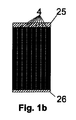
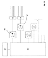
図1aは、アルミニウムストランドプロファイル10の横断面図である。図示は縮尺どおりではない。図示したストランドプロファイル10は8個の第1の領域を有し、これらの第1の領域は電池保持器4として構成されており、それぞれ2個のガルバニ電池1を保持するようになされている。
FIG. 1 a is a cross-sectional view of an
図1bは、アルミニウムストランドプロファイル10の側面図である。図示は縮尺どおりではない。図示したストランドプロファイル10は8個の第1の領域を有し、これらの第1の領域は電池保持器4として構成されており、それぞれ2個のガルバニ電池1を保持するようになされている。2個の電池保持器4の領域境界部は破線で示されている。図示したストランドプロファイル10には、相対向している2つの側に蓋要素25と底部要素26とが付設されている。
FIG. 1 b is a side view of the
図2aは、本発明に係る装置の有利な実施形態を横断面図で示したものである。図示は縮尺どおりではない。図示した電池保持器4はそれぞれ1個の第1の壁要素9を有し、この第1の壁要素は角管として構成されている。電池保持器4はこの電池保持器4を等間隔で位置決めさせている第1の成形部材6と接着されている。図示した実施形態では、2個の電池保持器4の間にそれぞれ1個の伝熱手段3が配置されている。これらの伝熱手段はそれぞれ第1の流体通路8を1本のみ有しており、この第1の流体通路は本発明に係る装置を、第1の側からこの第1の側に対向している第2の側へと貫通している。
FIG. 2a shows an advantageous embodiment of the device according to the invention in a cross-sectional view. The illustration is not to scale. The illustrated
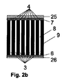
図2bは、本発明に係る装置の有利な実施形態の側面図である。図示は縮尺どおりではない。図示した電池保持器4は、それぞれ1個の第1の壁要素9を有し、この第1の壁要素は角管として構成されている。電池保持器4は、この電池保持器4を等間隔で位置決めさせている第1の成形部材6及び第2の成形部材7と接着されている。底部要素26は第1の成形部材6と螺合し、蓋要素25は第2の成形部材7と螺合している。図示した実施形態では、2個の電池保持器4の間にそれぞれ1個の伝熱手段3が配置されている。これらの伝熱手段3はそれぞれ第1の流体通路8を1本のみ有しており、この第1の流体通路は本発明に係る装置を、第1の側からこの第1の側に対向している第2の側へと貫通している。
Fig. 2b is a side view of an advantageous embodiment of the device according to the invention. The illustration is not to scale. The illustrated
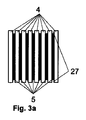
図3aは、本発明に係る寿命が延びたエネルギー蓄積ユニット用のアルミニウムストランドプロファイル10を示している。図示は縮尺どおりではない。図示したアルミニウムストランドプロファイル10の実施形態は8個の第1の部分を有し、これらの第1の部分は電池保持器4として構成されている。2個の第1の部分の間にはそれぞれアルミニウムストランドプロファイルの第2の部分5が1個配置されている。これらの第2の部分5は完全に金属から形成されており、2つの側に凹部27を有している。
FIG. 3a shows an
図3bは、本発明に係る装置の好ましい実施形態の側面図である。図示は縮尺どおりではない。図示した電池保持器4はそれぞれ1個の第1の壁要素9を有し、この第1の壁要素は角管として構成されている。2個の電池保持器4の間にはそれぞれ金属コアを備えた1個の伝熱手段3が配置されている。伝熱手段は、それぞれ円形の横断面を有する5本の第2の流体通路14を有し、これらの第2の流体通路は、本発明に係る装置を第1の側からこの第1の側に対向している第2の側へと貫通している。電池保持器4は第1の成形部材6及び第2の成形部材7と接着されている。底部要素26は第1の成形部材6と螺合し、蓋要素25は第2の成形部材7と螺合している。
FIG. 3b is a side view of a preferred embodiment of the device according to the invention. The illustration is not to scale. The illustrated
図4は、アルミニウムストランドプロファイル10の横断面図である。図示は縮尺どおりではない。図示したストランドプロファイル10は8個の第1の領域を有し、これらの第1の領域は電池保持器4として構成されており、それぞれ2個のガルバニ電池1を保持するようになされている。図示したストランドプロファイル10はさらに冷却フィン16を有し、これらの冷却フィンはこのストランドプロファイル10の表面積を増大させて、電磁放射の吸収及び放出を向上させるように設けられている。アルミニウムストランドプロファイルと冷却フィン16とは、好ましくは同じ材料から一体に形成されている。
FIG. 4 is a cross-sectional view of the
図5は、空冷部を備えた本発明に係る装置の縦断面図である。図示は縮尺どおりではない。図示したエネルギー蓄積ユニットは、それぞれ板状に構成された2個のガルバニ電池1から成る4つのグループを有している。それぞれのガルバニ電池は2個の電流導体11を有している。ガルバニ電池1の各電流導体11には、電気絶縁末端要素13が添設されている。ガルバニ電池1の4つのグループは、充電量を増大させるために並列に接続されている。1つのグループの内部では2個のガルバニ電池1が直列に接続されている。ただし、電気結線は図示していない。また、気密性、非導電性を有する、溶接されたフォイルとして形成される個々の電池ケースも図示していない。
FIG. 5 is a longitudinal sectional view of an apparatus according to the present invention provided with an air cooling unit. The illustration is not to scale. The illustrated energy storage unit has four groups of two
2個のガルバニ電池1は、それぞれ1個の電池保持器4に受容されている。図示した実施形態では、それぞれの電池保持器4は第1の壁要素9を1個のみ有し、この第1の壁要素9の横断面は長方形である。壁要素9は高伝熱性金属により薄壁状に形成され、ガルバニ電池1を取り囲んで空気の封入を防止している。またガルバニ電池は、1個のガルバニ電池1と壁要素9との間で高熱流の流動が可能であるように、壁要素9によって取り囲まれている。第1の壁要素9は、それぞれ第1の側で第1の成形部材6と接着され、この第1の側に対向している第2の側で第2の成形部材7と接着されている。蓋25は第2の成形部材7と螺合している。螺合による固定は破線で示している。
Each of the two
図示した実施形態では、各電池保持器4は板状に構成された位置補正手段2を有し、位置補正手段2はそれぞれ2個のガルバニ電池1に添設されて、これらガルバニ電池に面接触している。
In the illustrated embodiment, each
図示した実施形態では、1個の電池保持器4に少なくとも1個の伝熱手段3が添設されている。この伝熱手段3は第1の流体通路8を有し、この第1の流体通路は、本発明に係る装置を第1の側からこの第1の側に対向している第2の側へ貫通している。この流体通路8は、好ましくは、外気が貫流するように設けられている。作用的に結合しているガルバニ電池1と外気の温度とによって、これらガルバニ電池1に熱エネルギーが供給され、又は、これらガルバニ電池から熱エネルギーが放出される。
In the illustrated embodiment, at least one heat transfer means 3 is attached to one
本発明に係る装置の図示した実施形態では、流体通路8は2枚の高湿潤性不織布14を有し、この高湿潤性不織布は、それぞれ部分的に第1の壁要素9と接着され、これら第1の壁要素9の片側を部分的に第2の流体で湿潤させるように設けられている。
In the illustrated embodiment of the device according to the invention, the
図6は、流体冷却部を備えた本発明に係る装置の縦断面図である。図示は縮尺どおりではない。図示したエネルギー蓄積ユニットは、板状に構成されたそれぞれ2個のガルバニ電池1から成る4つのグループを有している。それぞれのガルバニ電池は2個の電流導体11を有している。ガルバニ電池1の各電流導体11には、電気絶縁末端要素13が添設されている。4つのグループは、充電量を増大させるために並列に接続されている。1つのグループの内部では2個のガルバニ電池1が直列に接続されている。但し、電気結線は図示していない。また、気密性で非導電性の、溶接されたフォイルとして形成される個々の電池ケースも図示していない。
FIG. 6 is a longitudinal sectional view of an apparatus according to the present invention provided with a fluid cooling section. The illustration is not to scale. The illustrated energy storage unit has four groups of two
2個のガルバニ電池1からなる各グループは、1個の電池保持器4に受容されている。図示した実施形態では、それぞれの電池保持器4は、第1の壁要素9を1個のみ有し、この第1の壁要素9の横断面は長方形である。壁要素9は高伝熱性金属により薄壁状に形成され、ガルバニ電池1を取り囲んで空気の封入を防止している。ガルバニ電池は、1個のガルバニ電池1と壁要素9との間で高熱流の流動が可能であるように、壁要素9によって取り囲まれている。第1の壁要素9はそれぞれ第1の側で第1の成形部材6と接着され、この第1の側に対向している第2の側で第2の成形部材7と接着されている。蓋25は第2の成形部材7と螺合している。
Each group of two
図示した実施形態では、それぞれの電池保持器4は、板状に構成された位置補正手段2を有し、位置補正手段2はそれぞれ2個のガルバニ電池1に添設されて、これらガルバニ電池と面接触している。
In the illustrated embodiment, each
図示した実施形態では、1個の電池保持器4に少なくとも1個の伝熱手段3が添設されている。この伝熱手段3は高伝熱性金属コアを有している。さらに、伝熱手段3はそれぞれ5本の第2の流体通路14を有している。流体通路14は円形の横断面を有し、そして連通要素を介して連通して対を成し、1本の連続した流体通路を形成したものとすることができる。流体通路14には温度調整された第2の流体が貫流し、ここで流体通路14の幾何学的構成と、第2の流体の物質特性及びその流速とは、流動ができるだけ高いレイノルズ数又はヌッセルト数を有するように選定されている。作用的に結合されているガルバニ電池1とこの第2の流体との温度によって、これらガルバニ電池に熱エネルギーが供給され、又は、これらガルバニ電池から熱エネルギーが放出される。
In the illustrated embodiment, at least one heat transfer means 3 is attached to one
図示した実施形態では、電池保持器4と伝熱手段3とは一体に作製され、図3aに対応したアルミニウムストランドプロファイルが使用されている。
In the illustrated embodiment, the
図7aは、気体状流体が貫流可能な流体通路14用の連通要素18を示している。この連通要素18の幾何学的構成は、アルミニウムストランドプロファイルの第2の領域に設けられる凹部(本図には図示していない)の幾何学的構成に適合している。図示した連通要素は、少なくとも2本の流体通路を、少なくとも部分的に連通させるために設けられている。好ましくは、1個のモジュールを形成するように統合された、2個の異なる本発明に係る装置に割り当てられる2本の流体通路を、この連通要素によって連通させる。特に、連通要素はU字状に構成されていてよい。U字状に構成した連通要素は、同じ伝熱手段に割り当てられる2本の流体通路を連通させるために用いる。
FIG. 7a shows a communication element 18 for a
図7bは、気体状流体が貫流可能な流体通路8用の連通要素19を示している。この連通要素19の幾何学的構成は、アルミニウムストランドプロファイルの第2の領域に設けられる凹部(本図には図示していない)の幾何学的構成に適合している。図示した連通要素は少なくとも2本の流体通路を、少なくとも部分的に連通させるために設けられている。好ましくは、1個のモジュールを形成するように統合された、2個の異なる本発明に係る装置に割り当てられる2本の流体通路を、この連通要素によって連通させる。特に、連通要素はU字状に構成されていてよい。U字状に構成した連通要素は、同じ伝熱器に割り当てられる2本の流体通路を連通させるために用いる。
FIG. 7b shows a communication element 19 for the
図8は、内部空冷部を備えた本発明に係る装置の縦断面図である。取り付けられたファン28は本発明に係る装置の内部で流体を、好ましくは外気を流動させる。発生する流体流は、本発明に係る装置の外側の電池保持器4によって誘導され、この外側の電池保持器はガルバニ電池1と位置補正手段2とを有していない。また、流体流は蓋要素25内に形成された流体通路によって誘導され、その流体は少なくとも電流導体11又は作用的に結合されている冷却体の周囲を流動する。さらに、流体流は底部要素26内に形成された流体通路によって誘導される。本発明に係る装置の内部で循環するこの流体流は、少なくとも部分的に温度調整用の熱交換器(図示せず)を貫流させることもできる。電流導体11又は作用的に結合されている冷却体及び流体の温度によって、熱エネルギーが電流導体11及び/又は作用的に結合されている冷却体に供給され、又は、これらから放出される。
FIG. 8 is a longitudinal sectional view of an apparatus according to the present invention having an internal air cooling unit. The mounted
図9は、本発明に係る装置の伝熱手段用の分配器の側面図であり、この分配器を第1の流体が貫流する。図示した分配器は、第2の流体を導入するための接続部28と、厚さ1.5mmの支持フレーム29と、それぞれ4mmの内径を備えた上部パイプ又は下部パイプ30,31とを有している。上部パイプ30は0.5mm径の孔33を部分的に有し、これらの孔は、上部パイプ30内を流動する第2の流体を、毛細管現象を生じる不織布34へと誘導する。毛細管現象を生じる不織布は、図示していない伝熱手段の第1の流体通路の壁と部分的に接着され、この流体通路壁を部分的に第2の流体で湿潤させる。分配器はさらに2個のウィングレット32を有し、このウィングレットは支持フレーム29に取り付けられている。ウィングレット32の配置は、第1の流体の実質的に層状の流動が渦を巻き、その際に第2の湿潤作用流体の液状から気体状への物質移動が向上するように、選定されている。
FIG. 9 is a side view of a distributor for heat transfer means of the apparatus according to the present invention, through which a first fluid flows. The distributor shown has a
図10は、本発明に係る装置の一実施形態の側面図である。図示した実施形態では、蓋要素25は本発明に係る装置を接続するためのくり抜き部35を有している。さらに、底部要素26は2個のT形溝36を有し、これらのT形溝は本発明による複数個の装置を固定するための固定要素を受容する。底部要素26はさらにスタッド37用の孔を有し、スタッドはT形溝36によって案内される固定要素を固定する。
FIG. 10 is a side view of an embodiment of an apparatus according to the present invention. In the illustrated embodiment, the
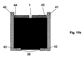
図11aは、1個のガルバニ電池1の平面図であり、このガルバニ電池は気密な溶接されたフォイルとして構成された電池ケース39によって取り囲まれ、2体構成のプロファイルフレーム38で受容されている。2体構成のプロファイルフレーム38は、U字状プロファイルを有し、受容されるガルバニ電池1に幾何学的に適合しており、アルミニウム及び/又はプラスチックにより作製されている。図示していないが、ガルバニ電池1をプロファイルフレーム38に固定するために、たとえばアクリル封止剤のような取付け用接着剤が用いられる。
FIG. 11 a is a plan view of a single
図11bは、プロファイルフレーム38で受容されるガルバニ電池1の側面図である。2体構成のプロファイルフレーム38はU字状プロファイルを有し、受容されるガルバニ電池1に幾何学的に適合し、アルミニウム及び/又はプラスチックにより作製されている。図示していないが、ガルバニ電池1をプロファイルフレーム38に固定するために、たとえばアクリル封止剤のような取り付け用接着剤が用いられる。図示した孔40,41,42,43,44,45,46は、ガルバニ電池1及び2体構成のプロファイルフレーム38を接着するための装置内で、これらの部材を位置決めするために用いる。特に、ガルバニ電池1又はプロファイルフレーム38を上記接着用装置内に固定するために、上記孔の大きさに幾何学的に適合したボルトを使用する。
FIG. 11 b is a side view of the
図12は、本発明に係る装置をケース及び第2の成形部材なしで示した平面図である。アルミニウムストランドプロファイル10は、電池保持器として構成された7個の第1の領域を有している。アルミニウムストランドプロファイル10は、さらに多数の冷却フィン16を有している。電池保持器にはそれぞれ2個のガルバニ電池1が装備され、これらのガルバニ電池は電池ケースによって取り囲まれてプロファイルフレーム38に受容されている。さらに、それぞれの電池保持器内には、2個のガルバニ電池1の間に位置決めされている位置補正手段が受容されている。本発明に係る装置の図示した実施形態では、スタッドを用いて固定されている接点要素38を備えたそれぞれ2個のガルバニ電池が直列に接続されている。図示した実施形態では、合計14個のガルバニ電池1の直列接続が生じる。
FIG. 12 is a plan view showing the apparatus according to the present invention without a case and a second molded member. The
図13はアキュムレータを温度調整するための制御装置及び測定器の本発明による配置構成を示している。制御装置51が図示されており、これに記憶装置52が接続されている。この記憶装置52内には、演算規則と、検出して評価される測定値と、温度所定値又は目標値とが記憶されている。この記憶装置52は、さらにアキュムレータの温度制御用設定値を含んでいる。温度制御するためのこれらの設定値を用いて、制御装置51は所定の方法に従いオンオフすることができる。制御装置51には、接続されているガルバニ電池の温度を検出するための第1の測定器57が結合されている。この第1の測定器50には、種々のサーモエレメントが接続されている切換えスイッチ53が結合されている。制御装置51には、さらに、電流を測定するための第2の測定器57が結合されている。この第2の測定器57には切換えスイッチ54が結合され、この切換えスイッチには種々の電流計が接続されている。さらに、制御装置51には、流体用の一連の搬送装置と、種々のスイッチに接続される制御線とが接続されている。
FIG. 13 shows an arrangement according to the present invention of a control device and a measuring device for adjusting the temperature of the accumulator. A
制御装置及び測定器のこの配置構成では、制御装置51は作動されるアキュムレータの温度制御を予測して実施することができる。なお、制御装置51の機能を他の既存の制御装置又は上位のバッテリー管理システムで代用させることもできる。
With this arrangement of control devices and measuring instruments, the
Claims (13)
少なくとも1個の内部空間(47)を備え、前記少なくとも1個のガルバニ電池(1)を少なくとも部分的に受容するために設けられている電池保持手段(4)と、
前記電池保持手段(4)の前記内部空間(47)を少なくとも部分的に取り囲み、前記少なくとも1個のガルバニ電池(1)と少なくとも部分的に作用的に結合している第1の壁要素(9)と、
前記少なくとも1個の第1の壁要素(9)と作用的に結合している伝熱手段(3)と、
前記伝熱手段(3)に付設され、第1の流体(48)を貫流させるために設けられている流体通路(8)と
を備えた電気エネルギーを蓄積するための装置において、
前記装置が、膨張するように構成された少なくとも1個の位置補正手段(2)を有し、少なくともこの位置補正手段(2)が少なくとも部分的に前記電池保持手段(4)の内部に配置されていることを特徴とする装置。 At least one galvanic cell (1);
Battery holding means (4) comprising at least one internal space (47) and provided for at least partially receiving said at least one galvanic battery (1);
A first wall element (9) at least partly surrounding the internal space (47) of the battery holding means (4) and at least partly operatively coupled to the at least one galvanic battery (1). )When,
Heat transfer means (3) operatively coupled to said at least one first wall element (9);
In a device for accumulating electrical energy, comprising a fluid passage (8) attached to the heat transfer means (3) and provided for allowing the first fluid (48) to flow through,
The apparatus has at least one position correction means (2) configured to expand, and at least the position correction means (2) is at least partially disposed within the battery holding means (4). A device characterized by that.
前記担持体が少なくとも1つの面が無機材料で被覆され、
物質透過性担持体として、好ましくは有機材料が使用され、この有機材料が好ましくは不織布として構成され、
前記有機材料が好ましくはポリマー、特に好ましくはポリエチレンテレフタラート(PET)を有し、
前記有機材料がイオン伝導性無機材料で被覆され、このイオン伝導性無機材料が好ましくは−40℃〜200℃の温度範囲でイオン伝導性があり、
前記イオン伝導性無機材料が、好ましくは、Zr、Al、Liのうちの少なくとも1つの元素の、酸化物、リン酸塩、硫酸塩、チタン酸塩、ケイ酸塩、アルミノケイ酸塩からなるグループの少なくとも1つの化合物であり、特に酸化ジルコニウムであり、
前記イオン伝導性無機材料が好ましくは100nm未満の最大径をもつ粒子を有していることを特徴とする、請求項1に記載の装置。 Said at least one galvanic cell has at least one separator, which preferably consists of a substance-permeable support, preferably partly permeable, ie with respect to at least one material. Substantially permeable, substantially impermeable with respect to at least one other material,
The carrier has at least one surface coated with an inorganic material;
As the material-permeable support, an organic material is preferably used, and the organic material is preferably configured as a nonwoven fabric.
The organic material preferably comprises a polymer, particularly preferably polyethylene terephthalate (PET),
The organic material is coated with an ion conductive inorganic material, and the ion conductive inorganic material is preferably ion conductive in a temperature range of −40 ° C. to 200 ° C.
The ion conductive inorganic material is preferably selected from the group consisting of oxide, phosphate, sulfate, titanate, silicate, aluminosilicate of at least one element of Zr, Al, Li. At least one compound, in particular zirconium oxide,
Device according to claim 1, characterized in that the ion-conducting inorganic material preferably has particles with a maximum diameter of less than 100 nm.
及び/又は、
記憶装置を有し、この記憶装置は前記制御手段に付設され、前記記憶装置が少なくともデータ及び/又は演算規則を記憶するために適している、
ことを特徴とする、上記請求項の少なくとも1項に記載の装置。 At least one second measuring means, which detects the current intensity of the current in the galvanic cell or the current intensity of the current from the galvanic battery, and this current intensity Suitable for sending to the control device,
And / or
Having a storage device, the storage device being attached to the control means, the storage device being suitable for storing at least data and / or calculation rules,
Device according to at least one of the preceding claims.
前記第1の測定手段が少なくとも一時的に1個のガルバニ電池の所定部位での温度を検出し、及び/又は、前記第2の測定手段が1個のガルバニ電池内の電流の強さ又は1個のガルバニ電池からの電流の強さを検出し、
前記制御手段が検出した前記温度と、これに対し予め設定された温度との温度差を特定し、
前記制御装置が、測定した前記温度、検出した前記温度差及び/又は検出した電流強さに基づいて、伝熱手段及び/又は流体用搬送手段をオンオフする
ことを特徴とする方法。 A method of operating a device according to at least one of the preceding claims,
The first measuring means at least temporarily detects the temperature at a predetermined part of one galvanic cell, and / or the second measuring means detects the current intensity in one galvanic cell or 1 Detects the strength of the current from each galvanic cell,
A temperature difference between the temperature detected by the control means and a temperature preset for the temperature is identified;
The control device turns on and off the heat transfer means and / or the fluid conveying means based on the measured temperature, the detected temperature difference and / or the detected current intensity.
(a)前記ストランドプロファイル(10)を所定の長さの部片に分割するステップと、
(b)前記ガルバニ電池(1)と前記位置補正手段(2)とを配置するステップと、
(c)これらの配置を前記電池保持手段(4)に押し込むステップ。 Battery holding means (4) for a device according to at least one of claims 1 to 11, equipped with at least one galvanic battery (1) and / or at least one position correcting means (2). A method of manufacturing using the strand profile (10) in the following steps;
(A) dividing the strand profile (10) into pieces of a predetermined length;
(B) arranging the galvanic cell (1) and the position correcting means (2);
(C) The step of pushing these arrangements into the battery holding means (4).
Applications Claiming Priority (3)
| Application Number | Priority Date | Filing Date | Title |
|---|---|---|---|
| DE102009048249A DE102009048249A1 (en) | 2009-10-05 | 2009-10-05 | Energy storage unit with extended life |
| DE102009048249.0 | 2009-10-05 | ||
| PCT/EP2010/005803 WO2011042122A1 (en) | 2009-10-05 | 2010-09-22 | Energy storage unit having extended service life |
Publications (2)
| Publication Number | Publication Date |
|---|---|
| JP2013506969A true JP2013506969A (en) | 2013-02-28 |
| JP2013506969A5 JP2013506969A5 (en) | 2013-10-17 |
Family
ID=43303824
Family Applications (1)
| Application Number | Title | Priority Date | Filing Date |
|---|---|---|---|
| JP2012532480A Pending JP2013506969A (en) | 2009-10-05 | 2010-09-22 | Energy storage unit with extended life |
Country Status (8)
| Country | Link |
|---|---|
| US (1) | US20120244394A1 (en) |
| EP (1) | EP2486621A1 (en) |
| JP (1) | JP2013506969A (en) |
| KR (1) | KR20120091109A (en) |
| CN (1) | CN102576917A (en) |
| BR (1) | BR112012007810A2 (en) |
| DE (1) | DE102009048249A1 (en) |
| WO (1) | WO2011042122A1 (en) |
Families Citing this family (11)
| Publication number | Priority date | Publication date | Assignee | Title |
|---|---|---|---|---|
| RU2012124033A (en) * | 2009-11-09 | 2013-12-20 | Энердел, Инк. | CONSTRUCTION AND THERMAL CONTROLLING ELEMENT |
| DE102009052508A1 (en) * | 2009-11-11 | 2011-05-12 | Carl Freudenberg Kg | Mechanically flexible and porous compensating element for tempering electrochemical cells |
| DE102011104433A1 (en) * | 2011-01-25 | 2012-07-26 | Bayerische Motoren Werke Aktiengesellschaft | Energy storage module for a device for power supply and method for producing such an energy storage module |
| DE102012205895A1 (en) * | 2012-04-11 | 2013-10-17 | Robert Bosch Gmbh | Energy storage cover module and method for mounting an energy storage cover module |
| DE102012224330A1 (en) | 2012-12-21 | 2014-04-03 | Continental Automotive Gmbh | Electrical battery device for use in e.g. electric vehicle, has sealing layer partly surrounding battery cell with elastic element to seal against environment, where expansion of cell leads to compression of elastic element |
| DE102014207531A1 (en) | 2014-04-22 | 2015-10-22 | Bayerische Motoren Werke Aktiengesellschaft | Galvanic element with solid-state cell stack |
| JP6123746B2 (en) * | 2014-07-11 | 2017-05-10 | 株式会社デンソー | Assembled battery |
| US10290911B2 (en) * | 2015-05-18 | 2019-05-14 | Toyota Motor Engineering & Manufacturing North America, Inc. | Cooling loops and vehicles incorporating the same |
| DE102017206564A1 (en) * | 2017-04-19 | 2018-10-25 | Robert Bosch Gmbh | Subassembly of a battery module, battery module with such a subunit and method for producing such |
| DE102017119465B4 (en) * | 2017-08-25 | 2020-12-03 | Dr. Ing. H.C. F. Porsche Aktiengesellschaft | Carrier device for receiving battery cells of a battery device of a vehicle, battery module for a battery device of a vehicle and method for adapting a carrier device |
| DE102021115657A1 (en) | 2021-06-17 | 2022-12-22 | Dr. Ing. H.C. F. Porsche Aktiengesellschaft | Liquid-cooled automotive traction battery module |
Citations (7)
| Publication number | Priority date | Publication date | Assignee | Title |
|---|---|---|---|---|
| JPH08148187A (en) * | 1994-11-18 | 1996-06-07 | Honda Motor Co Ltd | Battery assembly with temperature control mechanism |
| JP2001511594A (en) * | 1997-07-25 | 2001-08-14 | ミネソタ マイニング アンド マニュファクチャリング カンパニー | Thermal management device and method for semiconductor energy storage device |
| JP2005518642A (en) * | 2002-02-19 | 2005-06-23 | スリーエム イノベイティブ プロパティズ カンパニー | Temperature control apparatus and method for high energy electrochemical cells |
| JP2005536857A (en) * | 2002-08-24 | 2005-12-02 | デグサ アクチエンゲゼルシャフト | Separator for use in a high energy battery and method for producing the same |
| JP2007500920A (en) * | 2003-07-31 | 2007-01-18 | アヴェスター リミティッド パートナーシップ | Polymer battery with temperature converter |
| JP2008518394A (en) * | 2005-02-14 | 2008-05-29 | エルジー・ケム・リミテッド | Air filter automatic management device for battery pack and automatic management method thereof |
| JP2008300288A (en) * | 2007-06-01 | 2008-12-11 | Sanyo Electric Co Ltd | Battery pack |
Family Cites Families (10)
| Publication number | Priority date | Publication date | Assignee | Title |
|---|---|---|---|---|
| US4578324A (en) * | 1984-10-05 | 1986-03-25 | Ford Aerospace & Communications Corporation | Active cooling system for electrochemical cells |
| DE29612571U1 (en) * | 1996-07-19 | 1996-09-12 | Varta Batterie | Multi-cell accumulator battery with cooling |
| DE19848446C1 (en) * | 1998-10-21 | 2000-04-13 | Daimler Chrysler Ag | Electric storage battery casing e.g. for automobile battery, has cooling air stream directed across battery cells filtered for removal of humidity and moisture |
| JP4662530B2 (en) * | 2004-01-20 | 2011-03-30 | パナソニック株式会社 | Battery pack |
| WO2005069408A1 (en) * | 2004-01-20 | 2005-07-28 | Matsushita Electric Industrial Co., Ltd. | Battery pack |
| US20060110657A1 (en) * | 2004-11-15 | 2006-05-25 | William Stanton | Battery assembly for use in an uninterruptible power supply system and method |
| JP4445447B2 (en) * | 2005-09-15 | 2010-04-07 | 株式会社東芝 | Nonaqueous electrolyte battery and battery pack |
| CN101326658B (en) * | 2005-12-06 | 2010-09-29 | Lg化学株式会社 | Organic/ inorganic composite separator having morphology gradient, manufacturing method thereof and electrochemical device containing the same |
| KR100949331B1 (en) * | 2006-06-09 | 2010-03-26 | 삼성에스디아이 주식회사 | Secondary battery module |
| US20080299452A1 (en) * | 2007-05-31 | 2008-12-04 | Densei-Lambda K.K. | Battery pack |
-
2009
- 2009-10-05 DE DE102009048249A patent/DE102009048249A1/en not_active Withdrawn
-
2010
- 2010-09-22 CN CN2010800446756A patent/CN102576917A/en active Pending
- 2010-09-22 EP EP10760261A patent/EP2486621A1/en not_active Withdrawn
- 2010-09-22 KR KR20127010397A patent/KR20120091109A/en not_active Application Discontinuation
- 2010-09-22 BR BR112012007810A patent/BR112012007810A2/en not_active IP Right Cessation
- 2010-09-22 JP JP2012532480A patent/JP2013506969A/en active Pending
- 2010-09-22 WO PCT/EP2010/005803 patent/WO2011042122A1/en active Application Filing
- 2010-09-22 US US13/499,995 patent/US20120244394A1/en not_active Abandoned
Patent Citations (7)
| Publication number | Priority date | Publication date | Assignee | Title |
|---|---|---|---|---|
| JPH08148187A (en) * | 1994-11-18 | 1996-06-07 | Honda Motor Co Ltd | Battery assembly with temperature control mechanism |
| JP2001511594A (en) * | 1997-07-25 | 2001-08-14 | ミネソタ マイニング アンド マニュファクチャリング カンパニー | Thermal management device and method for semiconductor energy storage device |
| JP2005518642A (en) * | 2002-02-19 | 2005-06-23 | スリーエム イノベイティブ プロパティズ カンパニー | Temperature control apparatus and method for high energy electrochemical cells |
| JP2005536857A (en) * | 2002-08-24 | 2005-12-02 | デグサ アクチエンゲゼルシャフト | Separator for use in a high energy battery and method for producing the same |
| JP2007500920A (en) * | 2003-07-31 | 2007-01-18 | アヴェスター リミティッド パートナーシップ | Polymer battery with temperature converter |
| JP2008518394A (en) * | 2005-02-14 | 2008-05-29 | エルジー・ケム・リミテッド | Air filter automatic management device for battery pack and automatic management method thereof |
| JP2008300288A (en) * | 2007-06-01 | 2008-12-11 | Sanyo Electric Co Ltd | Battery pack |
Also Published As
| Publication number | Publication date |
|---|---|
| BR112012007810A2 (en) | 2016-08-30 |
| DE102009048249A1 (en) | 2011-04-07 |
| EP2486621A1 (en) | 2012-08-15 |
| CN102576917A (en) | 2012-07-11 |
| WO2011042122A1 (en) | 2011-04-14 |
| US20120244394A1 (en) | 2012-09-27 |
| KR20120091109A (en) | 2012-08-17 |
Similar Documents
| Publication | Publication Date | Title |
|---|---|---|
| JP2013506969A (en) | Energy storage unit with extended life | |
| JP2012523655A (en) | Storage battery with increased durability | |
| JP7027641B2 (en) | A cooling jacket with a non-uniform flow path for cooling the surface of the battery cell and a battery module containing it. | |
| CN110770931B (en) | Flexible cooling plate for battery | |
| US20170365895A1 (en) | Energy storage system with heat pipe thermal management | |
| KR101526667B1 (en) | Device for cooling and heating battery module of vehicle | |
| US10818987B2 (en) | Battery cell with integrated vapor chamber | |
| US9902284B2 (en) | Heating and cooling apparatus for a battery | |
| KR102208720B1 (en) | Battery Heat Sink for Cooling by Phase Change Materials and Method thereof | |
| KR101084969B1 (en) | Battery Module Having Temperature Sensor and Battery Pack Employed with the Same | |
| US20060210868A1 (en) | Secondary battery module | |
| KR100667943B1 (en) | Secondary battery module | |
| JP5834975B2 (en) | Electrical device module | |
| JP2010277863A (en) | Vehicular battery system and vehicle loading the same | |
| CN108432033B (en) | Battery module, battery pack including the same, and vehicle | |
| JP2012518873A (en) | Battery with conductor device | |
| JP7309910B2 (en) | Battery module including cell frame | |
| Lin et al. | Heating lithium-ion batteries at low temperatures for onboard applications: recent progress, challenges and prospects | |
| JP2020500409A (en) | Battery module | |
| EP4002549A2 (en) | Battery cooling apparatus for electric vehicle and method of manufacturing same | |
| US20120177973A1 (en) | Electrochemical energy storage and method for cooling or heating an electrochemical energy storage | |
| KR20160058674A (en) | Battery Module | |
| CN110534840B (en) | Battery module and battery heat exchange method | |
| CN106921006A (en) | A kind of battery thermostat and system | |
| KR101772061B1 (en) | Battery pack containing thermoelectric devices for controlling temperature and cold-starting method for electric vehicle using the same |
Legal Events
| Date | Code | Title | Description |
|---|---|---|---|
| A521 | Request for written amendment filed |
Free format text: JAPANESE INTERMEDIATE CODE: A523 Effective date: 20130827 |
|
| A621 | Written request for application examination |
Free format text: JAPANESE INTERMEDIATE CODE: A621 Effective date: 20130828 |
|
| A977 | Report on retrieval |
Free format text: JAPANESE INTERMEDIATE CODE: A971007 Effective date: 20140924 |
|
| A131 | Notification of reasons for refusal |
Free format text: JAPANESE INTERMEDIATE CODE: A131 Effective date: 20141111 |
|
| A521 | Request for written amendment filed |
Free format text: JAPANESE INTERMEDIATE CODE: A821 Effective date: 20150216 |
|
| RD04 | Notification of resignation of power of attorney |
Free format text: JAPANESE INTERMEDIATE CODE: A7424 Effective date: 20150216 |
|
| A02 | Decision of refusal |
Free format text: JAPANESE INTERMEDIATE CODE: A02 Effective date: 20150407 |