JP2013505603A - Network-relay station signaling for downlink transparent relay stations - Google Patents
Network-relay station signaling for downlink transparent relay stations Download PDFInfo
- Publication number
- JP2013505603A JP2013505603A JP2012529082A JP2012529082A JP2013505603A JP 2013505603 A JP2013505603 A JP 2013505603A JP 2012529082 A JP2012529082 A JP 2012529082A JP 2012529082 A JP2012529082 A JP 2012529082A JP 2013505603 A JP2013505603 A JP 2013505603A
- Authority
- JP
- Japan
- Prior art keywords
- retransmission
- base station
- subframe
- frequency band
- relay station
- Prior art date
- Legal status (The legal status is an assumption and is not a legal conclusion. Google has not performed a legal analysis and makes no representation as to the accuracy of the status listed.)
- Pending
Links
Images


Classifications
-
- H—ELECTRICITY
- H04—ELECTRIC COMMUNICATION TECHNIQUE
- H04B—TRANSMISSION
- H04B7/00—Radio transmission systems, i.e. using radiation field
- H04B7/24—Radio transmission systems, i.e. using radiation field for communication between two or more posts
- H04B7/26—Radio transmission systems, i.e. using radiation field for communication between two or more posts at least one of which is mobile
- H04B7/2603—Arrangements for wireless physical layer control
- H04B7/2606—Arrangements for base station coverage control, e.g. by using relays in tunnels
-
- H—ELECTRICITY
- H04—ELECTRIC COMMUNICATION TECHNIQUE
- H04L—TRANSMISSION OF DIGITAL INFORMATION, e.g. TELEGRAPHIC COMMUNICATION
- H04L1/00—Arrangements for detecting or preventing errors in the information received
- H04L1/12—Arrangements for detecting or preventing errors in the information received by using return channel
- H04L1/16—Arrangements for detecting or preventing errors in the information received by using return channel in which the return channel carries supervisory signals, e.g. repetition request signals
- H04L1/18—Automatic repetition systems, e.g. Van Duuren systems
- H04L1/1867—Arrangements specially adapted for the transmitter end
- H04L1/1887—Scheduling and prioritising arrangements
-
- H—ELECTRICITY
- H04—ELECTRIC COMMUNICATION TECHNIQUE
- H04L—TRANSMISSION OF DIGITAL INFORMATION, e.g. TELEGRAPHIC COMMUNICATION
- H04L1/00—Arrangements for detecting or preventing errors in the information received
- H04L2001/0092—Error control systems characterised by the topology of the transmission link
- H04L2001/0097—Relays
-
- H—ELECTRICITY
- H04—ELECTRIC COMMUNICATION TECHNIQUE
- H04W—WIRELESS COMMUNICATION NETWORKS
- H04W84/00—Network topologies
- H04W84/02—Hierarchically pre-organised networks, e.g. paging networks, cellular networks, WLAN [Wireless Local Area Network] or WLL [Wireless Local Loop]
- H04W84/04—Large scale networks; Deep hierarchical networks
- H04W84/042—Public Land Mobile systems, e.g. cellular systems
- H04W84/047—Public Land Mobile systems, e.g. cellular systems using dedicated repeater stations
Landscapes
- Engineering & Computer Science (AREA)
- Computer Networks & Wireless Communication (AREA)
- Signal Processing (AREA)
- Mobile Radio Communication Systems (AREA)
- Radio Relay Systems (AREA)
Abstract
無線通信ネットワークにおいて下りリンク再送信を移動局に提供する方法において、無線通信ネットワークは、トランスペアレント中継局に通信可能に結合された基地局を有する。基地局は、移動局から再送信の要求を受信し、再送信のリソースをスケジューリングし、制御リンクを介して再送信のスケジューリング情報をトランスペアレント中継局に伝達し、トランスペアレント中継局は、制御リンクで再送信のスケジューリング情報を受信し、再送信周波数帯域の再送信サブフレームで再送信を移動局に送信する。 In a method for providing downlink retransmission to a mobile station in a wireless communication network, the wireless communication network includes a base station that is communicatively coupled to a transparent relay station. The base station receives a retransmission request from the mobile station, schedules retransmission resources, transmits retransmission scheduling information to the transparent relay station via the control link, and the transparent relay station retransmits the transmission link via the control link. The transmission scheduling information is received, and the retransmission is transmitted to the mobile station in the retransmission subframe of the retransmission frequency band.
Description
本発明は、無線通信に関し、特にトランスペアレント中継局(transparent relay)を使用した無線通信ネットワークでDL再送信を移動局に提供する方法及びシステムに関する。 The present invention relates to wireless communication, and more particularly, to a method and system for providing DL retransmission to a mobile station in a wireless communication network using a transparent relay.
音声、データ及び他のコンテンツのような様々な種類の通信コンテンツを提供するために、無線通信システムが広く展開されている。これらのシステムは、利用可能な送信リソース(例えば、周波数チャネル及び/又は時間間隔)を共有することにより、複数の無線端末の通信を同時にサポート可能なマルチプルアクセスシステムであることがある。送信リソースは共有されるため、送信リソースの効率的な割り当てが重要になる。この理由は、送信リソースの利用に影響を与え、個々の端末ユーザにより認識されるサービス品質に影響を与えるからである。1つのこのような通信システムは、複数の無線端末が直交周波数分割多重(OFDM:Orthogonal Frequency-Division Multiplexing)を使用してマルチプルアクセスを実行する直交周波数分割多元アクセス(Orthogonal Frequency-Division Multiple Access)システムである。 Wireless communication systems are widely deployed to provide various types of communication content such as voice, data and other content. These systems may be multiple access systems that can simultaneously support communication of multiple wireless terminals by sharing available transmission resources (eg, frequency channels and / or time intervals). Since transmission resources are shared, efficient allocation of transmission resources is important. This is because it affects the use of transmission resources and affects the quality of service recognized by individual terminal users. One such communication system is an Orthogonal Frequency-Division Multiple Access (Orthogonal Frequency-Division Multiple Access) system in which multiple wireless terminals perform multiple access using Orthogonal Frequency-Division Multiplexing (OFDM). It is.
OFDMは、全体のシステム帯域幅を複数の直交周波数サブチャネルに分割するマルチキャリア変調技術であり、各直交周波数サブチャネルは、データで変調され得る各サブキャリアに関連付けられる。サブチャネルは直交化されるため、サブチャネルの間の何らかのスペクトルの重複が可能になり、高いスペクトル効率をもたらす。OFDMシステムでは、ユーザデータストリームは、低減したレートの並列ストリームに分割され、それぞれ得られたサブストリームが別々のサブキャリアを変調する。 OFDM is a multi-carrier modulation technique that divides the overall system bandwidth into multiple orthogonal frequency subchannels, with each orthogonal frequency subchannel associated with each subcarrier that may be modulated with data. Since the subchannels are orthogonalized, some spectral overlap between the subchannels is possible, resulting in high spectral efficiency. In an OFDM system, a user data stream is divided into parallel streams at a reduced rate, and each resulting substream modulates a separate subcarrier.
OFDMAでは、共有無線媒体へのアクセスは、2次元(シンボルの単位の時間及び論理サブチャネルの単位の周波数)に及ぶフレームを使用してスケジューリングされる。データバーストは、フレーム内において、BSにより特定の制御メッセージを介してスケジューリングされる2次元(すなわち、時間及び周波数)のデータ領域で伝達される。各フレームは、下りリンク(DL:downlink)及び上りリンク(UL:uplink)サブフレームに分割される。前者は、BSによりMSにデータを送信するために使用され、MSは、後者でBSに送信する。 In OFDMA, access to a shared wireless medium is scheduled using frames that span two dimensions (time in symbols and frequency in logical subchannels). Data bursts are conveyed in a two-dimensional (ie, time and frequency) data domain within a frame that is scheduled by the BS via specific control messages. Each frame is divided into a downlink (DL) and an uplink (UL) subframe. The former is used by the BS to send data to the MS, and the MS sends to the BS in the latter.
OFDM通信システムの例は、IEEE(Institute of Electrical and Electronics Engineering)標準の無線802.11a、b、g及びnに従って規定された無線ローカルエリアネットワーク(WLAN:wireless local area network)プロトコル(以下、“Wi-Fi”と呼ぶ)、IEEE802.16に従って規定された無線MAN(Wireless Man)/固定BWA(Fixed broadband wireless access)標準(以下、“WiMAX”と呼ぶ)、HSOPA(High Speed OFDM Packet Access)又はE-UTRA(Evolved UMTS Terrestrial Radio Access)の無線インタフェースを有する移動ブロードバンドの3GPP LTE(Long Term Evolution)プロトコル、3GPP2 UMB(Ultra Mobile Broadband)プロトコル、デジタル無線システムのDAB(Digital Audio Broadcasting)プロトコル、HD(Hybrid Digital)無線、地上波デジタルTVシステムのDVB-T(Digital Video Broadcasting-Terrestrial)、セルラ通信システムのFlash-OFDM等のような無線プロトコルを含むが、これらに限定されない。OFDM技術を使用する有線プロトコルは、ASDL(Asymmetric Digital Subscriber Line)及びVDSL(Very High Bitrate Digital Subscriber Line)のブロードバンドアクセス、BPL(Broadband over Power Lines)を含む電力線通信(PLC:Power line communication)、並びにMoCA(Multimedia over Coax Alliance)ホームネットワーキングを含む。 An example of an OFDM communication system is a wireless local area network (WLAN) protocol (hereinafter referred to as “Wi-Wire”) defined in accordance with IEEE (Institute of Electrical and Electronics Engineering) standard wireless 802.11a, b, g and n. Fi ”), wireless MAN (Wireless Man) / Fixed broadband wireless access (BWA) standard (hereinafter referred to as“ WiMAX ”), HSOPA (High Speed OFDM Packet Access) or E- Mobile broadband 3GPP LTE (Long Term Evolution) protocol with UTRA (Evolved UMTS Terrestrial Radio Access) radio interface, 3GPP2 UMB (Ultra Mobile Broadband) protocol, DAB (Digital Audio Broadcasting) protocol for digital radio systems, HD (Hybrid Digital) ) DVB-T (Digital Video Broadcasting-Terrestrial) for wireless and terrestrial digital TV systems, Flash for cellular communication systems -Including, but not limited to, wireless protocols such as OFDM. Wired protocols that use OFDM technology include ASDL (Asymmetric Digital Subscriber Line) and VDSL (Very High Bitrate Digital Subscriber Line) broadband access, BPL (Broadband over Power Lines) power line communication (PLC), and Includes MoCA (Multimedia over Coax Alliance) home networking.
3GPP LTEでは、以下の物理チャネルが規定されている。
●下りリンク(DL)
○物理ブロードキャストチャネル(PBCH:Physical Broadcast Channel):このチャネルは、ネットワークへのアクセスを要求する移動局(ユーザ装置(UE:user equipment)とも呼ばれる)のシステム情報を伝達する。
○物理下りリンク制御チャネル(PDCCH:Physical Downlink Control Channel):この物理チャネルの主な目的は、スケジューリング情報を伝達することである。
○物理ハイブリッドARQインジケータチャネル(PHICH:Physical Hybrid ARQ Indicator Channel):このチャネルは、ハイブリッドARQ状態を報告するために使用される。
○物理下りリンク共有チャネル(PDSCH:Physical Downlink Shared Channel):このチャネルは、ユニキャスト及びページング機能のために使用される。
○物理マルチキャストチャネル(PMCH:Physical Multicast Channel):この物理チャネルは、マルチキャスト目的のためにシステム情報を伝達する。
○物理制御フォーマットインジケータチャネル(PCFICH:Physical Control Format Indicator Channel):このチャネルは、UEがPDSCHを復号化することを可能にする情報を提供する。
●上りリンク(UL)
○物理上りリンク制御チャネル(PUCCH:Physical Uplink Control Channel):このチャネルは、制御チャネルで送信できる1つ以上のUEからのユーザシグナリングデータを伝達するために使用される。例えば、PUCCHは、肯定応答及び再送要求と、サービススケジューリング要求と、UEにより測定されたチャネル品質情報とをシステムに伝達する。
○物理上りリンク共有チャネル(PUSCH:Physical Uplink Shared Channel):このチャネルは、共有データで送信できる1つ以上の移動局からのユーザデータを伝達するために使用される。
○物理ランダムアクセスチャネル(PRACH:Physical Random Access Channel):この上りリンク物理チャネルは、UEが無線通信システムにアクセスすることを試みるときに、UEがアクセス要求をランダムに送信することを可能にする。
In 3GPP LTE, the following physical channels are defined.
● Downlink (DL)
O Physical Broadcast Channel (PBCH): This channel conveys system information of a mobile station (also called user equipment (UE)) that requests access to the network.
O Physical Downlink Control Channel (PDCCH): The main purpose of this physical channel is to carry scheduling information.
O Physical Hybrid ARQ Indicator Channel (PHICH): This channel is used to report hybrid ARQ status.
O Physical Downlink Shared Channel (PDSCH): This channel is used for unicast and paging functions.
O Physical Multicast Channel (PMCH): This physical channel carries system information for multicast purposes.
O Physical Control Format Indicator Channel (PCFICH): This channel provides information that allows the UE to decode the PDSCH.
● Uplink (UL)
O Physical Uplink Control Channel (PUCCH): This channel is used to carry user signaling data from one or more UEs that can be transmitted on the control channel. For example, PUCCH communicates acknowledgment and retransmission requests, service scheduling requests, and channel quality information measured by the UE to the system.
O Physical Uplink Shared Channel (PUSCH): This channel is used to convey user data from one or more mobile stations that can be transmitted with shared data.
O Physical Random Access Channel (PRACH): This uplink physical channel allows the UE to randomly transmit an access request when the UE attempts to access the wireless communication system.
無線通信システムは、1つ以上の中継局(RS:relay station)を通じて基地局(BS:base station)と移動局(MS:mobile station)との間でユーザデータ及び場合によっては制御情報を中継するために、中継方式を使用することがある。中継方式は、基地局のカバレッジ、範囲、スループット及び/又はキャパシティを拡張するために使用されてもよい。中継局は、中継局の通信範囲内のMSが中継局を通じてBSと通信することができるように、BSへの送信/BSからの送信を再現することができる。中継局は、BS及びMSの双方と無線通信できるため、バックホールリンクを必要としない。この種類のネットワークは、マルチホップネットワークと呼ばれることがある。この理由は、MSと有線接続との間に1つより多くの無線接続が存在し得るからである。特定のネットワーク構成に応じて、特定のMSは、1つ以上の周辺中継局及び/又は1つ以上の周辺BSを介してネットワークアクセスを取得することがある。更に、中継局自体が、特定のBSに接続するための1つ以上の利用可能なパスの選択肢を有することがある。BS又はRSとMSとの間の無線リンクはアクセスリンクと呼ばれ、BSとRSとの間のリンク又はRSの対の間のリンクは中継リンクと呼ばれる。 A wireless communication system relays user data and possibly control information between a base station (BS) and a mobile station (MS) through one or more relay stations (RS). Therefore, a relay method may be used. The relay scheme may be used to extend the coverage, range, throughput and / or capacity of the base station. The relay station can reproduce the transmission to / from the BS so that the MS within the communication range of the relay station can communicate with the BS through the relay station. Since the relay station can wirelessly communicate with both the BS and the MS, no backhaul link is required. This type of network is sometimes referred to as a multi-hop network. This is because there can be more than one wireless connection between the MS and the wired connection. Depending on the particular network configuration, a particular MS may obtain network access via one or more peripheral relay stations and / or one or more peripheral BSs. Further, the relay station itself may have one or more available path options for connecting to a particular BS. The radio link between the BS or RS and the MS is called the access link, and the link between the BS and RS or the link between the RS pair is called the relay link.
通常の中継局は、2つの異なるモード(トランスペアレント(transparent)及び非トランスペアレント(non-transparent))のうち一方で動作する。トランスペアレントRSは、トランスペアレントRSに接続されたMSがBSから直接的に制御情報を受信するため、制御情報を送信せず、データトラヒックのみを中継する。非トランスペアレントRSは、制御情報とデータトラヒックとを送信する。 A normal relay station operates in one of two different modes: transparent and non-transparent. In the transparent RS, since the MS connected to the transparent RS receives control information directly from the BS, the control information is not transmitted, and only data traffic is relayed. The non-transparent RS transmits control information and data traffic.
ハイブリッド自動再送要求(HARQ:hybrid automatic repeat-request)動作は、無線通信システムにおける誤り制御に使用され得る。HARQでは、受信機は、メッセージの誤りを検出し、送信機からのメッセージの再送信を自動的に要求する。HARQ要求(“NACK”)の受信に応じて、送信機は、誤りが続かない限り、正確に受信されるまでメッセージを再送信する。1つの変形例では、HARQは、前方誤り訂正(FEC:forward error correction)を誤り訂正符号と結合する。 A hybrid automatic repeat-request (HARQ) operation may be used for error control in a wireless communication system. In HARQ, the receiver detects a message error and automatically requests retransmission of the message from the transmitter. In response to receiving the HARQ request (“NACK”), the transmitter resends the message until it is received correctly unless errors continue. In one variation, HARQ combines forward error correction (FEC) with an error correction code.
LTEは、DLで非同期HARQ送信を使用する。非同期ARQでは、受信機は、いつ再送信が送信されるかを事前に認識しないため、制御情報がデータと共に送信されなければならない。これは、対応するPDSCH送信と同時にPDCCHでリソース割り当てメッセージを送信することにより実現される。この方式の利点は、どのMSがいずれかのサブフレーム中にデータを送信されるかを判定する際にスケジューリングアルゴリズムがかなりの自由度を有するという点にある。 LTE uses asynchronous HARQ transmission in the DL. With asynchronous ARQ, the receiver does not know in advance when a retransmission will be sent, so control information must be sent with the data. This is realized by transmitting a resource allocation message on the PDCCH simultaneously with the corresponding PDSCH transmission. The advantage of this scheme is that the scheduling algorithm has a considerable degree of freedom in determining which MS is to transmit data in any subframe.
トランスペアレント中継局が使用されるLTEシステムでは、RSは、BSと同時にMSにDL HARQ再送信を送信することにより、システム性能を改善することを支援し得る。しかし、どのようにBS及びRSが同時のDL HARQ再送信を調整できるかについて問題が生じる。再送信の前に、RSが同じパケットを同時に送信するために同じリソースを使用できるように、RSは、どの物理リソース(時間及び周波数)がBSによるパケットの再送信に使用されるかを認識しなければならない。しかし、DL HARQ再送信は非同期であるため、NACKが受信された場合、BSは、再送信のための1つのサブフレームにおいてPDCCH及びPDSCHを送信する。制御シグナリング領域及びデータ送信領域は時分割多重(TDM:time division multiplexing)方式で絶えず多重されるため、2つの領域の間にガード時間が存在しない。PDCCHは、各サブフレームの最初のn個(n=1、2又は3)のOFDMシンボルで送信され、PDSCHは、残りの(N-n)個(Nは、各サブフレームのOFDMシンボルの数)のOFDMシンボルを通じて送信される。RSが連続するシンボルの間で受信モードから送信モードに切り替えることは困難である。また、RSがPDCCHで再送信制御情報を復号化し、同じサブフレームにおいてPDSCHで再送信を準備することも困難である。更に、或る状況では、PCFICHにより伝達されるPDCCHの数がサブフレーム毎に変化する可能性があり、これはRSに対してPCFICHを復号化し、PDCCHの開始を判定し、同じサブフレームにおいてPDSCHで再送信を準備することを要求する。 In LTE systems where transparent relay stations are used, the RS may help improve system performance by sending DL HARQ retransmissions to the MS at the same time as the BS. However, a problem arises as to how BS and RS can coordinate simultaneous DL HARQ retransmissions. Prior to retransmission, the RS knows which physical resources (time and frequency) are used for retransmission of the packet by the BS so that the RS can use the same resources to transmit the same packet simultaneously. There must be. However, since DL HARQ retransmission is asynchronous, when NACK is received, the BS transmits PDCCH and PDSCH in one subframe for retransmission. Since the control signaling region and the data transmission region are constantly multiplexed by a time division multiplexing (TDM) method, there is no guard time between the two regions. PDCCH is transmitted in the first n (n = 1, 2 or 3) OFDM symbols in each subframe, and PDSCH is the remaining (Nn) (N is the number of OFDM symbols in each subframe). It is transmitted through OFDM symbols. It is difficult to switch from the reception mode to the transmission mode between symbols with consecutive RSs. It is also difficult for RS to decode retransmission control information with PDCCH and prepare for retransmission with PDSCH in the same subframe. In addition, in some situations, the number of PDCCHs carried by PCFICH may change from subframe to subframe, which decodes PCFICH for RS, determines the start of PDCCH, and uses PDSCH in the same subframe. Request to prepare for retransmission at
同期HARQ(すなわち、再送信が所定のサブフレームでスケジューリングされる)の使用は、前述の問題のいくつかを軽減し得るが、このような手法はスケジューラに望ましくない制約を持ち込む可能性がある。 Although the use of synchronous HARQ (ie, retransmissions are scheduled in a given subframe) may alleviate some of the aforementioned problems, such an approach may introduce undesirable constraints on the scheduler.
トランスペアレント中継システムにおいて下りリンク再送信のための改善した方式の必要性が存在する。 There is a need for an improved scheme for downlink retransmissions in transparent relay systems.
本発明の態様によれば、無線通信ネットワークにおいて下りリンク再送信を移動局に提供する方法が提供される。無線通信ネットワークは、トランスペアレント中継局に通信可能に結合された基地局を有する。この方法によれば、基地局は、移動局から再送信の要求を受信し、再送信のリソースをスケジューリングし、制御リンクを介して再送信のスケジューリング情報をトランスペアレント中継局に伝達し、トランスペアレント中継局は、制御リンクで再送信のスケジューリング情報を受信し、再送信周波数帯域の再送信サブフレームで再送信を移動局に送信する。 According to an aspect of the present invention, a method for providing downlink retransmissions to a mobile station in a wireless communication network is provided. The wireless communication network includes a base station that is communicatively coupled to a transparent relay station. According to this method, the base station receives a retransmission request from the mobile station, schedules retransmission resources, transmits retransmission scheduling information to the transparent relay station via the control link, and transmits the transparent relay station to the transparent relay station. Receives retransmission scheduling information on the control link and transmits the retransmission to the mobile station in a retransmission subframe of the retransmission frequency band.
本発明の更なる態様では、無線通信ネットワークの基地局が提供され、基地局は、移動局から再送信の要求を受信し、再送信のリソースをスケジューリングし、制御リンクを介して再送信のスケジューリング情報をトランスペアレント中継局に伝達するように動作可能なコントローラを有し、スケジューリング情報の伝達は、トランスペアレント中継局が再送信周波数帯域の再送信サブフレームで再送信を移動局に送信することを可能にする。 In a further aspect of the invention, a base station of a wireless communication network is provided, wherein the base station receives a retransmission request from a mobile station, schedules retransmission resources, and schedules retransmission over a control link. Having a controller operable to communicate information to the transparent relay station, the transmission of scheduling information allows the transparent relay station to transmit a retransmission to the mobile station in a retransmission subframe of the retransmission frequency band To do.
本発明の更なる態様では、無線通信ネットワークのトランスペアレント中継局が提供され、トランスペアレント中継局は、制御リンクで基地局から、移動局への再送信のためのスケジューリング情報を受信し、再送信周波数帯域の再送信サブフレームで再送信を移動局に送信するように動作可能なコントローラを有する。 In a further aspect of the present invention, a transparent relay station of a wireless communication network is provided, wherein the transparent relay station receives scheduling information for retransmission from a base station to a mobile station over a control link and transmits a retransmission frequency band. Having a controller operable to transmit a retransmission to the mobile station in a number of retransmission subframes.
本発明の他の態様及び特徴は、添付図面と共に本発明の特定の実施例の以下の詳細な説明を読むことにより、当業者に明らかになる。 Other aspects and features of the present invention will become apparent to those of ordinary skill in the art by reading the following detailed description of specific embodiments of the invention in conjunction with the accompanying drawings.
図面には、本発明の実施例が一例のみとして示されている。 In the drawings, embodiments of the invention are shown by way of example only.
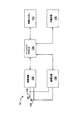
ここで図面を参照する。図面において、同様の参照符号は同様の要素を示す。図1は、複数のセル12内での無線通信を制御する基地局コントローラ(BSC:base station controller)10を示しており、複数のセルは、対応する基地局(BS:base station)14によりサービス提供される。或る構成では、各セルは、複数のセクタ13に更に分割される(図示せず)。一般的に、各基地局14は、移動端末16とのOFDMを使用した通信を容易にする。移動端末16は、対応する基地局16に関連するセル12内にある。基地局14に対する移動端末16の移動は、チャネル状況におけるかなりの変動を生じる。図示のように、基地局14及び移動端末16は、通信のための空間ダイバーシチを提供するために、複数のアンテナを含んでもよい。以下に詳細に説明するように、中継局(relay station)15は、基地局14と移動端末16との間の通信を支援してもよい。移動端末16は、いずれかのセル12、セクタ13(図示せず)、基地局14又は中継局15から他のセル12、セクタ13(図示せず)、基地局14又は中継局15にハンドオフされてもよい18。或る構成では、基地局14は、バックホールネットワーク11で各ネットワーク及び他のネットワーク(コアネットワーク又はインターネット(双方とも図示せず)等)と通信する。或る構成では、基地局コントローラ10は必要ない。
Reference is now made to the drawings. In the drawings, like reference numerals indicate like elements. FIG. 1 shows a base station controller (BSC) 10 that controls radio communication in a plurality of
図2は、基地局14の例を示している。基地局14は、一般的に、制御システム20と、ベースバンドプロセッサ22と、送信回路24と、受信回路26と、アンテナ28と、ネットワークインタフェース30とを含む。受信回路26は、移動端末16(図3に図示する)及び中継局15(図4に図示する)により提供された1つ以上の遠隔送信機から、情報を運ぶ無線周波数信号を受信する。低雑音増幅器及びフィルタ(図示せず)は、処理のために信号からブロードバンド干渉を増幅及び除去するように協調してもよい。ダウンコンバージョン及びデジタル化回路(図示せず)は、フィルタリングされた受信信号を中間又はベースバンド周波数信号にダウンコンバートする。中間又はベースバンド周波数信号は、1つ以上のデジタルストリームにデジタル化される。
FIG. 2 shows an example of the
ベースバンドプロセッサ22は、デジタル化された受信信号を処理し、受信信号で伝達された情報又はデータビットを抽出する。典型的には、この処理は、復調、復号化及び誤り訂正動作を有する。従って、ベースバンドプロセッサ22は、一般的には、1つ以上のデジタルシグナルプロセッサ(DSP:digital signal processor)又は特定用途向け集積回路(ASIC:application-specific integrated circuit)に実装される。受信情報は、ネットワークインタフェース30を介して無線ネットワークを通じて送信される、或いは、直接的に又は中継局15の支援により、基地局14によりサービス提供される他の移動端末16に送信される。
The
送信側では、ベースバンドプロセッサ22は、制御システム20の制御で、ネットワークインタフェース30からデジタル化されたデータ(音声、データ又は制御情報を表してもよい)を受信し、送信のためにデータを符号化する。符号化されたデータは、送信回路24に出力され、そこで、所望の送信周波数を有する1つ以上のキャリア信号により変調される。電力増幅器(図示せず)は、変調されたキャリア信号を送信に適したレベルに増幅し、マッチングネットワーク(matching network)(図示せず)を通じて変調されたキャリア信号をアンテナ28に配信する。変調及び処理の詳細は、以下に詳細に説明する。
On the transmitting side, the
図3は、移動端末16の例を示している。基地局14と同様に、移動端末16は、制御システム32と、ベースバンドプロセッサ34と、送信回路36と、受信回路38と、アンテナ40と、ユーザインタフェース回路42とを含む。受信回路38は、1つ以上の基地局14及び中継局15から情報を運ぶ無線周波数信号を受信する。低雑音増幅器及びフィルタ(図示せず)は、処理のために信号からブロードバンド干渉を増幅及び除去するように協調してもよい。ダウンコンバージョン及びデジタル化回路(図示せず)は、フィルタリングされた受信信号を中間又はベースバンド周波数信号にダウンコンバートする。中間又はベースバンド周波数信号は、1つ以上のデジタルストリームにデジタル化される。
FIG. 3 shows an example of the
ベースバンドプロセッサ34は、デジタル化された受信信号を処理し、受信信号で伝達された情報又はデータビットを抽出する。典型的には、この処理は、復調、復号化及び誤り訂正動作を有する。ベースバンドプロセッサ34は、一般的には、1つ以上のデジタルシグナルプロセッサ(DSP:digital signal processor)又は特定用途向け集積回路(ASIC:application-specific integrated circuit)に実装される。
The
送信について、ベースバンドプロセッサ34は、制御システム32からデジタル化されたデータ(音声、ビデオ、データ又は制御情報を表してもよい)を受信し、送信のためにデータを符号化する。符号化されたデータは、送信回路36に出力され、そこで、所望の送信周波数にある1つ以上のキャリア信号を変調するために変調器により変調される。電力増幅器(図示せず)は、変調されたキャリア信号を送信に適したレベルに増幅し、マッチングネットワーク(図示せず)を通じて変調されたキャリア信号をアンテナ40に配信する。当業者に利用可能な様々な変調及び処理技術が、直接的に又は中継局を介して移動端末と基地局との間で信号を送信するために使用される。
For transmission, the
OFDM変調では、送信帯域は複数の直交搬送波に分割される。各搬送波は、送信されるデジタルデータに従って変調される。OFDMは送信帯域を複数のキャリアに分割するため、キャリア毎の帯域幅は減少し、キャリア毎の変調時間は増加する。複数のキャリアが並列して送信されるため、いずれかの所与のキャリアのデジタルデータ又はシンボルの送信レートは、単一のキャリアが使用される場合より低い。 In OFDM modulation, the transmission band is divided into a plurality of orthogonal carriers. Each carrier wave is modulated according to the transmitted digital data. Since OFDM divides the transmission band into a plurality of carriers, the bandwidth for each carrier decreases and the modulation time for each carrier increases. Since multiple carriers are transmitted in parallel, the transmission rate of digital data or symbols for any given carrier is lower than when a single carrier is used.
OFDM変調は、送信される情報について逆高速フーリエ変換(IFFT:Inverse Fast Fourier Transform)の性能を利用する。復調について、受信信号での高速フーリエ変換(FFT:Fast Fourier Transform)の性能は、送信された情報を回復する。実際に、IFFT及びFFTは、それぞれ逆離散フーリエ変換(IDFT:Inverse Discrete Fourier Transform)及び離散フーリエ変換(DFT:Discrete Fourier Transform)を実行するデジタル信号処理により提供される。従って、OFDM変調の特徴は、送信チャネル内の複数の帯域について直交搬送波が生成される点にある。変調された信号は、比較的低い送信レートを有し、各帯域内に留まることができるデジタル信号である。個々の搬送波は、デジタル信号により直接的に変調されない。その代わりに、全ての搬送波は、IFFT処理により同時に変調される。 OFDM modulation utilizes the performance of Inverse Fast Fourier Transform (IFFT) for transmitted information. For demodulation, the performance of Fast Fourier Transform (FFT) on the received signal recovers the transmitted information. Actually, IFFT and FFT are provided by digital signal processing that performs Inverse Discrete Fourier Transform (IDFT) and Discrete Fourier Transform (DFT), respectively. Therefore, the characteristic of OFDM modulation is that orthogonal carriers are generated for a plurality of bands in the transmission channel. The modulated signal is a digital signal that has a relatively low transmission rate and can remain within each band. Individual carriers are not directly modulated by digital signals. Instead, all carriers are modulated simultaneously by IFFT processing.
一実施例では、OFDMは、基地局14から移動端末16への下りリンク送信に少なくとも使用されることが好ましい。各基地局14は、“n”個の送信アンテナ28(n>=1)を備えており、各移動端末16は、“m”個の受信アンテナ40(m>=1)を備えている。特に、各アンテナは、適切なデュプレクサ又はスイッチを使用して受信及び送信に使用可能であり、簡潔にするためにのみこのようにラベルが付与されている。
In one embodiment, OFDM is preferably used at least for downlink transmission from the
中継局15が使用される場合、OFDMは、基地局14から中継局15への下りリンク送信と、中継局15から移動装置16への下りリンク送信とに使用されることが好ましい。
When
図4は、例示的な中継局15を示している。基地局14及び移動端末16と同様に、中継局15は、制御システム132と、ベースバンドプロセッサ134と、送信回路136と、受信回路138と、アンテナ130と、中継回路142とを含む。中継回路142は、中継局14が基地局16と移動端末16との間の通信を支援することを可能にする。受信回路138は、1つ以上の基地局14及び移動端末16から情報を運ぶ無線周波数信号を受信する。低雑音増幅器及びフィルタ(図示せず)は、処理のために信号からブロードバンド干渉を増幅及び除去するように協調してもよい。ダウンコンバージョン及びデジタル化回路(図示せず)は、フィルタリングされた受信信号を中間又はベースバンド周波数信号にダウンコンバートする。中間又はベースバンド周波数信号は、1つ以上のデジタルストリームにデジタル化される。
FIG. 4 shows an
ベースバンドプロセッサ134は、デジタル化された受信信号を処理し、受信信号で伝達された情報又はデータビットを抽出する。典型的には、この処理は、復調、復号化及び誤り訂正動作を有する。ベースバンドプロセッサ134は、一般的には、1つ以上のデジタルシグナルプロセッサ(DSP:digital signal processor)又は特定用途向け集積回路(ASIC:application-specific integrated circuit)に実装される。
The
送信について、ベースバンドプロセッサ134は、制御システム132からデジタル化されたデータ(音声、ビデオ、データ又は制御情報を表してもよい)を受信し、送信のためにデータを符号化する。符号化されたデータは、送信回路136に出力され、そこで、所望の送信周波数にある1つ以上のキャリア信号を変調するために変調器により変調される。電力増幅器(図示せず)は、変調されたキャリア信号を送信に適したレベルに増幅し、マッチングネットワーク(図示せず)を通じて変調されたキャリア信号をアンテナ130に配信する。前述のように、当業者に利用可能な様々な変調及び処理技術が、直接的に又は中継局を介して間接的に移動端末と基地局との間で信号を送信するために使用される。
For transmission, the
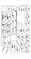
図5を参照して、論理OFDM送信アーキテクチャについて説明する。まず、基地局コントローラ10は、直接的に又は中継局15の支援により、様々な移動端末16に送信されるデータを基地局14に送信する。以下に詳細に説明するように、基地局14は、送信用のデータをスケジューリングするため及びスケジューリングされたデータを送信するための適切な変調及び符号化方式(MCS:modulation and coding scheme)を選択するために、移動端末に関連するチャネル品質インジケータ(CQI:channel quality indicator)値を使用する。CQIは、移動端末16からの直接的に受信されてもよく、移動端末16により提供された情報に基づいて基地局14で決定されてもよい。いずれの場合でも、各移動端末16に関連するCQI値は、例えば、信号対干渉比(SIR:signal-to-interference ratio)と、チャネル振幅(又は応答)がOFDM周波数帯域を通じて変化する程度との関数でもよい。
With reference to FIG. 5, a logical OFDM transmission architecture will be described. First, the
ビットのストリームであるスケジューリングされたデータ44は、データスクランブル化ロジック46を使用してデータに関連するピーク対平均電力比を低減するようにスクランブル化される。スクランブル化されたデータの巡回冗長検査(CRC:cyclic redundancy check)は、CRC付加ロジック48を使用して決定され、スクランブル化されたデータに付与される。次に、チャネル符号化ロジック50を使用して、チャネル符号化が実行され、移動端末16での回復及び誤り訂正を容易にするためにデータに冗長性を効果的に付加する。以下に詳細に説明するように、特定の移動端末16のチャネル符号化は、その移動端末に関連する現在のCQI値に基づく。或る実装では、チャネル符号化ロジック50は、既知のTurbo符号化技術を使用する。符号化されたデータは、符号化に関連するデータ展開を補うために、レートマッチング(rate matching)ロジック52により処理される。
The scheduled
ビットインターリーバロジック54は、符号化されたデータのビットを体系的に並び替え、連続的なデータビットのロスを最小化する。結果のデータビットは、マッピングロジック56により、選択されたベースバンド変調に応じて対応するシンボルに体系的にマッピングされる。直交振幅変調(QAM:Quadrature Amplitude Modulation)又は四相位相シフトキーイング(QPSK:Quadrature Phase Shift Key)変調が使用されることが好ましい。以下に詳細に説明するように、変調の程度は、特定の移動端末のCQI値に基づいて選択される。シンボルは、シンボルインターリーバロジック58を使用して、周波数選択性フェージングにより生じる周期的なデータロスに対する送信信号の耐性を更に増強するために体系的に並び替えられてもよい。
The bit
この時点で、ビットのグループは、振幅及び位相コンステレーションの位置を表すシンボルにマッピングされる。空間ダイバーシチが望まれる場合、シンボルのブロックは、時空ブロック符号(STC:space-time block code)符号化ロジック60により処理される。STC符号化ロジック60は、送信信号を干渉に対してより耐性のあるようにし、移動端末16で容易に復号されるように、シンボルを変更する。STC符号化ロジック60は、入来するシンボルを処理し、基地局14の送信アンテナ28の数に対応する“n”個の出力を提供する。図5に関して前述した制御システム20及び/又はベースバンドプロセッサ22は、STC符号化を制御するためにマッピング制御信号を提供する。この時点で、“n”個の出力のシンボルが、送信されて移動端末16により回復可能なデータを表すことを仮定する。
At this point, the group of bits is mapped to a symbol representing the position of the amplitude and phase constellation. If space diversity is desired, the block of symbols is processed by a space-time block code (STC)
この例では、基地局14が2つのアンテナ28(n=2)を有しており、STC符号化ロジック60がシンボルの2つの出力ストリームを提供することを仮定する。従って、STC符号化ロジック60により出力される各シンボルストリームは、理解を容易にするために別々に図示されている対応するIFFTプロセッサ62に送信される。当業者は、このようなデジタル信号処理を提供するために、1つ以上のプロセッサが単独で又はここに記載の他の処理と組み合わせて使用されてもよいことを認識する。IFFTプロセッサ62は、逆フーリエ変換を提供するために各シンボルで動作することが好ましい。IFFTプロセッサ62の出力は、時間領域でのシンボルを提供する。時間領域のシンボルはフレームにグループ化され、フレームは、プレフィックス挿入ロジック64によりプレフィックスに関連付けられる。結果の信号のそれぞれは、デジタル領域で中間周波数にアップコンバートされ、対応するデジタルアップコンバート(DUC:digital up-conversion)及びデジタル・アナログ(D/A)変換回路66を介してアナログ信号に変換される。結果の(アナログ)信号は、所望のRF周波数で同時に変調され、増幅され、RF回路68及びアンテナ28を介して送信される。特に、目的の移動端末16により知られているパイロット信号は、サブキャリア間に分散される。以下に詳細に説明するように、移動端末16は、チャネル推定のためにパイロット信号を使用する。
In this example, assume that the
基地局14から直接的な又は中継局15の支援による移動端末16による送信信号の受信を示す図6に参照が行われる。移動端末16の各アンテナ40に送信信号が到達すると、各信号は、対応するRF回路70により復調及び増幅される。簡潔且つ明瞭にするために、2つの受信パスのうち1つのみを詳細に説明及び図示する。アナログ・デジタル(A/D)変換器及びダウンコンバート回路72は、デジタル処理のために、アナログ信号をデジタル化してダウンコンバートする。結果のデジタル化された信号は、受信信号レベルに基づいてRF回路70の増幅器の利得を制御するために、自動利得制御回路(AGC:automatic gain control)74により使用されてもよい。
Reference is made to FIG. 6 showing reception of transmission signals by the
まず、デジタル化された信号は、同期ロジック76に提供される。同期ロジック76は、複数のOFDMシンボルをバッファに入れて、2つの連続するOFDMシンボルの間の自己相関を計算する粗い同期ロジック78を含む。相関結果の最大値に対応する結果の時間インデックスは、ヘッダに基づいて正確なフレーム開始位置を決定するために細かい同期ロジック80により使用される細かい同期検索ウィンドウを決定する。細かい同期ロジック80の出力は、フレーム整列ロジック84によるフレーム取得を容易にする。適切なフレーム整列は、次のFFT処理が時間領域から周波数領域への正確な変換を提供するために重要である。細かい同期アルゴリズムは、ヘッダにより伝達される受信パイロット信号と既知のパイロットデータのローカルコピーとの間の相関に基づく。フレーム整列の取得が生じると、OFDMシンボルのプレフィックスは、プレフィックス除去ロジック86で除去され、結果のサンプルは、周波数オフセット訂正ロジック88に送信される。周波数オフセット訂正ロジック88は、送信機及び受信機の一致しないローカル発振器により生じたシステム周波数オフセットを補う。同期ロジック78は、周波数オフセット及びクロック推定ロジック82を含むことが好ましい。周波数オフセット及びクロック推定ロジック82は、ヘッダに基づき、送信信号でのこのような効果を推定し、適切にOFDMシンボルを処理するためにこれらの推定を訂正ロジック88に提供することに役立てる。
First, the digitized signal is provided to
この時点で、時間領域のOFDMシンボルは、FFT処理ロジック90を使用して周波数領域に変換する準備ができている。結果は周波数領域のシンボルであり、周波数領域のシンボルは、処理ロジック92に送信される。処理ロジック92は、分散パイロット抽出ロジック94を使用して分散したパイロット信号を抽出し、チャネル推定ロジック96を使用して抽出されたパイロット信号に基づいてチャネル推定を決定し、チャネル再構成ロジック98を使用して全てのサブキャリアについてチャネル応答を提供する。サブキャリア毎のチャネル応答を決定するために、基本的には、パイロット信号は、時間及び周波数の双方において既知のパターンでOFDMサブキャリアを通じてデータシンボル間に分散した複数のパイロットシンボルである。図6を参照し続けると、処理ロジックは、特定の時間の特定のサブキャリアで想定されるパイロットシンボルと受信したパイロットシンボルとを比較し、パイロットシンボルが送信されたサブキャリアのチャネル応答を決定する。結果は、パイロットシンボルが提供されない残りのサブキャリアの全てではなくてもほとんどのチャネル応答を推定するように補間される。実際に補間されたチャネル応答は、OFDMチャネルのサブキャリアの全てではなくてもほとんどのチャネル応答を含む全体のチャネル応答を推定するために使用される。
At this point, the time-domain OFDM symbols are ready to be converted to the frequency domain using the
各受信パスのチャネル応答から導かれる周波数領域のシンボル及びチャネル再構成情報は、STC復号化器100に提供される。STC復号化器100は、双方の受信パスでSTC復号化を提供し、送信シンボルを回復する。チャネル再構成情報は、各周波数領域のシンボルを処理するときに送信チャネルの効果を除去するのに十分な等化情報をSTC復号化器100に提供する。本発明に関して、中継局は、他の基地局又は端末として動作してもよい。
Frequency domain symbols and channel reconfiguration information derived from the channel response of each receive path are provided to the
回復されたシンボルは、シンボルデインターリーバロジック102を使用して逆の順序に配置される。シンボルデインターリーバロジック102は、送信機のシンボルインターリーバロジック58に対応する。デインターリーブされたシンボルは、デマッピングロジック104を使用して、対応するビットストリームに復調又はデマッピングされる。ビットは、ビットデインターリーバロジック106を使用してデインターリーブされる。ビットデインターリーバロジック106は、送信アーキテクチャのビットインターリーバロジック54に対応する。デインターリーブされたビットは、レートデマッチングロジック108により処理され、最初にスクランブル化されたデータ及びCRCチェックサムを回復するためにチャネル復号化ロジック110に提示される。従って、CRCロジック112は、CRCチェックサムを除去し、通常の方法でスクランブル化されたデータを検査し、既知の基地局のデスクランブル化コードを使用してデスクランブル化するためにこれをデスクランブル化ロジック114に提供し、元々送信されたデータ116を回復する。
The recovered symbols are placed in reverse order using
データ116の回復と並行して、CQI値又は少なくとも基地局14でCQI値を生成するのに十分な情報が決定され、基地局14に送信される。前述のように、CQI値は、信号対干渉比(SIR:signal-to-interference ratio)と、チャネル応答がOFDM周波数帯域の様々なサブキャリアを通じて変化する程度との関数でもよい。この実施例では、情報を送信するために使用されるOFDM周波数帯域の各サブキャリアのチャネル利得は、チャネル利得がOFDM周波数帯域を通じて変化する程度を決定するために、相互に比較される。変動の程度を測定するために複数の技術が利用可能であるが、1つの技術は、データを送信するために使用されているOFDM周波数帯域を通じた各サブキャリアのチャネル利得の標準偏差を計算することである。
In parallel with the recovery of
或る実施例では、シングルキャリア周波数分割多元アクセス(SC-FDMA:Single Carrier Frequency Division Multiple Access)は、移動局16からの上りリンク送信に使用される。SC-FDMAは、3GPP LTEブロードバンド無線の第4世代(4G)無線インタフェースの上りリンク等に取り入れられた変調及びマルチプルアクセス方式である。図7A及び7Bを参照すると、本発明の一実施例により提供されたSISO(single-in single-output)構成の例示的なSC-FDMA送信機及び受信機が示されている。SISOでは、移動局は1つのアンテナで送信し、基地局及び/又は中継局は1つのアンテナで受信する。図7A及びBは、LTE SC-FDMA上りリンクについて送信機及び受信機で必要な基本的な信号処理ステップを示している。SC-FDMA及びOFDMAの全体の送受信処理に複数の類似点が存在する。OFDMAとSC-FDMAとの間のこれらの共通の側面は、この明細書を考慮したときに当業者に明らかであるため、概して“OFDMA送信回路”及び“OFDMA受信回路”として示されている。SC-FDMAは、変調シンボルのDFTプリコーディング及び復調シンボルの対応するIDFTのため、OFDMAとは明確に異なる。このプリコーディングのため、SC-FDMAサブキャリアは、OFDMAサブキャリアの場合のように独立して変調されない。その結果、SC-FDMA信号のピーク対平均電力比(PAPR:peak-to-average power ratio)は、OFDMA信号のPAPRより低い。低いPAPRは、送信電力効率について移動局にとってかなり利点がある。
In one embodiment, single carrier frequency division multiple access (SC-FDMA) is used for uplink transmission from
図1〜7は、本発明の実施例を実施するために使用され得る通信システムの1つの特定の例を提供している。実施例は、特定の例とは異なるが、ここに記載した実施例の実装に従った方法で動作するアーキテクチャを有する通信システムで実施されてもよいことが分かる。 1-7 provide one specific example of a communication system that can be used to implement an embodiment of the present invention. It will be appreciated that the embodiments are different from the specific examples, but may be implemented in a communication system having an architecture that operates in a manner consistent with the implementation of the embodiments described herein.
本発明の実施例によれば、中継局15は、トランスペアレントモードで動作しつつ、DL再送信(例えば、DL HARQ再送信)を支援することができる。より具体的には、基地局14は、再送信を送信する前に、制御リンク(ここでは、“ネットワーク対中継局リンク”と呼ばれる)で再送信情報を中継局15に伝達するように構成される。制御リンクは、帯域内でもよく、帯域外でもよい。これにより、中継局15は、基地局14と同時に(例えば、同じOFDMAサブフレーム内で)再送信を送信してもよい。
According to the embodiment of the present invention, the
図8は、本発明の実施例に従ってトランスペアレント中継局により支援されるDL再送信のステップを示すフローチャートを示している。図示のように、ステップ802において、基地局(BS)は、移動局(MS)から再送信の要求(例えば、HARQ NACK)を受信する。ステップ804において、BSは、MSがセル端又はセル端の近くに存在しており、潜在的に再送信のためにトランスペアレント中継局(RS)の支援を必要とするものとして識別する。ステップ806において、BSは、再送信のリソースをスケジューリングし、ステップ808において、BSは、ネットワーク対中継局リンクを介して再送信のスケジューリング情報をRSに伝達する。以下に詳細に説明するように、或る実施例では、再送信のリソースは、再送信の1サブフレーム前にスケジューリングされてもよい。再送信のためのRSの支援により、瞬時のチャネル変動を取得するスケジューラの要件が簡単になる。ステップ810において、BSは、スケジューリングされた再送信をMSに送信する。RSでは、ステップ812において、RSは、再送信情報を取得し、ステップ814において、RSは、BSと同時にBSと同じ周波数帯域でスケジューリングされた再送信をMSに送信する。
FIG. 8 shows a flowchart illustrating the steps of DL retransmission supported by a transparent relay station according to an embodiment of the present invention. As shown, in
図9は、ネットワーク対中継局リンクが帯域内であるDL再送信方式を示している。すなわち、ネットワーク対中継局リンクは、ネットワーク対移動局アクセスリンクと同じ周波数帯域F1を占有する。図示のように、サブフレーム(n)において、NRは、周波数帯域F1で基地局(eNB)から再送信情報を受信し、サブフレーム(n+1)において、中継局(NR)は、基地局14と同時に再送信データをUEに送信する。双方の再送信は、同じ周波数帯域F1で行われる。帯域内のネットワーク対中継局リンクは、PDSCH又はPDCCHの或る予約リソースを使用してもよい。新たな制御チャネルフォーマットが規定されてもよい。例えば、セル端の移動局のグループについてPDCCHが規定されてもよい。 FIG. 9 shows a DL retransmission scheme in which the network-to-relay station link is in band. That is, the network-to-relay station link occupies the same frequency band F1 as the network-to-mobile station access link. As shown, in subframe (n), NR receives retransmission information from the base station (eNB) in frequency band F1, and in subframe (n + 1), the relay station (NR) At the same time, the retransmission data is transmitted to the UE. Both retransmissions are performed in the same frequency band F1. An in-band network-to-relay link may use certain reserved resources of PDSCH or PDCCH. A new control channel format may be defined. For example, PDCCH may be defined for a group of mobile stations at the cell edge.
図10A及び10Bは、ネットワーク対中継局リンクが帯域外であるDL HARQ再送信方式を示している。すなわち、ネットワーク対中継局リンク及びネットワーク対移動局アクセスリンクは、それぞれ異なる周波数帯域F2及びF1を占有する。或る実施例では、ネットワーク対中継局リンクに割り当てられた周波数帯域F2は、専用の周波数帯域でもよい。例えば、或る実施例では、F2は、2.5GHz帯域のような‘新たな’スペクトルでもよい。図示のように、NRは、eNBから信号を受信し、異なる周波数帯域で信号をUEに送信する。2つの選択肢が提示されている。図10Aに示す第1の選択肢では、eNBは、サブフレーム(n)においてHARQに関するPDCCHを送信し、NRは、サブフレーム(n+1)において再送信データをUEに送信する。図10Bに示す第2の選択肢では、eNBは、サブフレーム(n)においてHARQに関するPDCCHを送信し、NRは、サブフレーム(n)において再送信データをUEに送信する。第2の選択肢を採用した実施例では、対応するPDSCHが送信される前にNRがそのPDCCHを復号化することを可能にする十分なガード時間を提供するように、NR本位のPDCCHについて異なる制御チャネルフォーマットが規定されてもよい。 10A and 10B show a DL HARQ retransmission scheme where the network-to-relay link is out of band. That is, the network-to-relay station link and the network-to-mobile station access link occupy different frequency bands F2 and F1, respectively. In some embodiments, the frequency band F2 assigned to the network-to-relay link may be a dedicated frequency band. For example, in one embodiment, F2 may be a 'new' spectrum, such as a 2.5 GHz band. As illustrated, the NR receives a signal from the eNB and transmits the signal to the UE in different frequency bands. Two options are presented. In the first option shown in FIG. 10A, the eNB transmits PDCCH related to HARQ in subframe (n), and the NR transmits retransmission data to the UE in subframe (n + 1). In the second option shown in FIG. 10B, the eNB transmits PDCCH related to HARQ in subframe (n), and the NR transmits retransmission data to the UE in subframe (n). In an embodiment employing the second option, different controls for the NR-oriented PDCCH to provide sufficient guard time to allow the NR to decode the PDCCH before the corresponding PDSCH is transmitted. A channel format may be defined.
有利には、ここに記載の方式は、トランスペアレントモードで動作する中継局15が基地局14と同時にDL再送信を移動局16に送信することを可能にするため、トランスペアレント中継局のロバスト性を増加させ、その性能を拡張する。
Advantageously, the scheme described here increases the robustness of the transparent relay station by allowing the
当業者に他の変更が明らかになるため、本発明は、特許請求の範囲に規定される。 Since other modifications will be apparent to persons skilled in the art, the invention is defined in the claims.
Claims (24)
前記基地局において、
前記移動局から再送信の要求を受信するステップと、
前記再送信のリソースをスケジューリングするステップと、
制御リンクを介して前記再送信のスケジューリング情報を前記トランスペアレント中継局に伝達するステップと
前記トランスペアレント中継局において、
前記制御リンクで前記再送信の前記スケジューリング情報を受信するステップと、
再送信周波数帯域の再送信サブフレームで前記再送信を前記移動局に送信するステップと
を有する方法。 A method for providing a DL retransmission to a mobile station in a wireless communication network having a base station communicatively coupled to a transparent relay station, comprising:
In the base station,
Receiving a retransmission request from the mobile station;
Scheduling the retransmission resources;
Transmitting the retransmission scheduling information to the transparent relay station via a control link; and
Receiving the scheduling information of the retransmission on the control link;
Transmitting the retransmission to the mobile station in a retransmission subframe of a retransmission frequency band.
移動局から再送信の要求を受信し、
前記再送信のリソースをスケジューリングし、
制御リンクを介して前記再送信のスケジューリング情報をトランスペアレント中継局に伝達するように動作可能なコントローラを有し、
前記スケジューリング情報の前記伝達は、前記トランスペアレント中継局が再送信周波数帯域の再送信サブフレームで前記再送信を前記移動局に送信することを可能にする基地局。 A base station of a wireless communication network,
Receives a retransmission request from the mobile station,
Scheduling resources for the retransmission,
A controller operable to communicate the retransmission scheduling information to a transparent relay station over a control link;
The transmission of the scheduling information is a base station that allows the transparent relay station to transmit the retransmission to the mobile station in a retransmission subframe of a retransmission frequency band.
制御リンクで基地局から、移動局への再送信のためのスケジューリング情報を受信し、
再送信周波数帯域の再送信サブフレームで前記再送信を前記移動局に送信するように動作可能なコントローラを有するトランスペアレント中継局。 A transparent relay station of a wireless communication network,
Receives scheduling information for retransmission to the mobile station from the base station on the control link,
A transparent relay station having a controller operable to transmit the retransmission to the mobile station in a retransmission subframe of a retransmission frequency band.
Applications Claiming Priority (3)
| Application Number | Priority Date | Filing Date | Title |
|---|---|---|---|
| US24409809P | 2009-09-21 | 2009-09-21 | |
| US61/244,098 | 2009-09-21 | ||
| PCT/CA2010/001508 WO2011044667A2 (en) | 2009-09-21 | 2010-09-21 | Network-relay signaling for downlink transparent relay |
Publications (1)
| Publication Number | Publication Date |
|---|---|
| JP2013505603A true JP2013505603A (en) | 2013-02-14 |
Family
ID=43876620
Family Applications (1)
| Application Number | Title | Priority Date | Filing Date |
|---|---|---|---|
| JP2012529082A Pending JP2013505603A (en) | 2009-09-21 | 2010-09-21 | Network-relay station signaling for downlink transparent relay stations |
Country Status (9)
| Country | Link |
|---|---|
| EP (1) | EP2481238A4 (en) |
| JP (1) | JP2013505603A (en) |
| KR (1) | KR20150129094A (en) |
| CN (1) | CN102918884A (en) |
| BR (1) | BR112012006372B8 (en) |
| CA (1) | CA2774723C (en) |
| IN (1) | IN2012DN02390A (en) |
| RU (1) | RU2543977C2 (en) |
| WO (1) | WO2011044667A2 (en) |
Cited By (2)
| Publication number | Priority date | Publication date | Assignee | Title |
|---|---|---|---|---|
| JP2016533064A (en) * | 2013-07-03 | 2016-10-20 | インターデイジタル パテント ホールディングス インコーポレイテッド | Multi-band method for interference limited wireless local area network system |
| JP2017139662A (en) * | 2016-02-04 | 2017-08-10 | ソニー株式会社 | Communication apparatus, communication method, transmitter, and receiver |
Families Citing this family (5)
| Publication number | Priority date | Publication date | Assignee | Title |
|---|---|---|---|---|
| US9801028B2 (en) * | 2008-03-21 | 2017-10-24 | Apple Inc. | Multimedia broadcast multicast service (MBMS) utilizing spatial multiplexing |
| US9148213B2 (en) | 2012-05-04 | 2015-09-29 | Futurewei Technologies, Inc. | System and method for radio frequency repeating |
| CN103338508B (en) * | 2013-07-10 | 2015-09-16 | 武汉邮电科学研究院 | A kind of associating frequency deviation estimating method and system |
| ES2742039T3 (en) * | 2014-01-30 | 2020-02-12 | Alcatel Lucent | Communication techniques that use a repeat regime in an enhanced coverage region |
| EP4233207A1 (en) * | 2020-10-30 | 2023-08-30 | MediaTek Singapore Pte. Ltd. | Repeater for downlink transmission and uplink transmission |
Citations (1)
| Publication number | Priority date | Publication date | Assignee | Title |
|---|---|---|---|---|
| US20080049718A1 (en) * | 2006-04-03 | 2008-02-28 | Siemens Corporate Research, Inc. | Relay-Assisted HARQ Transmission System |
Family Cites Families (6)
| Publication number | Priority date | Publication date | Assignee | Title |
|---|---|---|---|---|
| AU2003904167A0 (en) * | 2003-08-08 | 2003-08-21 | Clipsal Intergrated Systems Pty Ltd | Radio network communication system and protocol using an automatic repeater |
| CN101174874A (en) * | 2006-11-03 | 2008-05-07 | 富士通株式会社 | Centralized-scheduler relay station for MMR extended 802.16E system |
| CN101345568B (en) * | 2007-07-09 | 2012-07-25 | 电信科学技术研究院 | Signal forwarding method and device of transparent relay station |
| EP2313990B1 (en) * | 2008-08-12 | 2018-05-23 | BlackBerry Limited | Enabling downlink transparent relay in a wireless communications network |
| US8953467B2 (en) * | 2008-09-08 | 2015-02-10 | Nokia Corporation | Adaptive transmission modes for transparent relay |
| CN101873609B (en) * | 2009-04-27 | 2013-03-20 | 电信科学技术研究院 | Data transmission method and device for relay system |
-
2010
- 2010-09-21 RU RU2012110922/07A patent/RU2543977C2/en active
- 2010-09-21 IN IN2390DEN2012 patent/IN2012DN02390A/en unknown
- 2010-09-21 WO PCT/CA2010/001508 patent/WO2011044667A2/en active Application Filing
- 2010-09-21 BR BR112012006372A patent/BR112012006372B8/en active IP Right Grant
- 2010-09-21 KR KR1020127010286A patent/KR20150129094A/en active Search and Examination
- 2010-09-21 CN CN2010800526089A patent/CN102918884A/en active Pending
- 2010-09-21 EP EP10822937.8A patent/EP2481238A4/en not_active Withdrawn
- 2010-09-21 CA CA2774723A patent/CA2774723C/en active Active
- 2010-09-21 JP JP2012529082A patent/JP2013505603A/en active Pending
Patent Citations (1)
| Publication number | Priority date | Publication date | Assignee | Title |
|---|---|---|---|---|
| US20080049718A1 (en) * | 2006-04-03 | 2008-02-28 | Siemens Corporate Research, Inc. | Relay-Assisted HARQ Transmission System |
Non-Patent Citations (1)
| Title |
|---|
| JPN6014003329; Nortel: 'More Design Aspects on Downlink Transparent Relay in LTE-A' 3GPP TSG-RAN1 Meeting #54bis R1-083866 , 20080929 * |
Cited By (4)
| Publication number | Priority date | Publication date | Assignee | Title |
|---|---|---|---|---|
| JP2016533064A (en) * | 2013-07-03 | 2016-10-20 | インターデイジタル パテント ホールディングス インコーポレイテッド | Multi-band method for interference limited wireless local area network system |
| JP2017139662A (en) * | 2016-02-04 | 2017-08-10 | ソニー株式会社 | Communication apparatus, communication method, transmitter, and receiver |
| US10555143B2 (en) | 2016-02-04 | 2020-02-04 | Sony Corporation | Communication device, communication method, transmission device and reception device |
| US11363429B2 (en) | 2016-02-04 | 2022-06-14 | Sony Corporatton | Communication device, communication method, transmission device and reception device |
Also Published As
| Publication number | Publication date |
|---|---|
| CN102918884A (en) | 2013-02-06 |
| RU2543977C2 (en) | 2015-03-10 |
| KR20150129094A (en) | 2015-11-19 |
| BR112012006372B8 (en) | 2021-10-26 |
| CA2774723C (en) | 2018-07-17 |
| RU2012110922A (en) | 2013-10-27 |
| IN2012DN02390A (en) | 2015-08-21 |
| CA2774723A1 (en) | 2011-04-21 |
| EP2481238A4 (en) | 2017-06-07 |
| BR112012006372A8 (en) | 2018-04-03 |
| EP2481238A2 (en) | 2012-08-01 |
| BR112012006372B1 (en) | 2021-04-20 |
| WO2011044667A3 (en) | 2011-07-21 |
| WO2011044667A2 (en) | 2011-04-21 |
| BR112012006372A2 (en) | 2016-03-29 |
Similar Documents
| Publication | Publication Date | Title |
|---|---|---|
| US9622229B2 (en) | Network relay signaling for downlink transparent relay | |
| JP5702387B2 (en) | Signaling and channel estimation for uplink transmit diversity | |
| JP5676596B2 (en) | Design of uplink control signals for wireless systems | |
| EP2313990A1 (en) | Enabling downlink transparent relay in a wireless communications network | |
| CA2774723C (en) | Network-relay signaling for downlink transparent relay | |
| US20110069772A1 (en) | Transmission of multicast broadcast service (mbs) traffic in a wireless environment | |
| US20110034197A1 (en) | Apparatus and method for signalling active assignments to a group of wireless stations | |
| US20130010760A1 (en) | Handover schemes for wireless systems | |
| JP5466241B2 (en) | Relaying technique suitable for user equipment in downlink | |
| US8649338B2 (en) | Apparatus and method for mobile assisted adaptive FFR | |
| KR20120065319A (en) | Apparatus and method for signalling active assignments to a group of wireless stations | |
| JP2013509741A (en) | Multicast / broadcast service (MBS) traffic transmission in a wireless environment | |
| US20110149846A1 (en) | Uplink control signal design for wireless system | |
| US20110069682A1 (en) | Ranging channel structures and methods |
Legal Events
| Date | Code | Title | Description |
|---|---|---|---|
| A621 | Written request for application examination |
Free format text: JAPANESE INTERMEDIATE CODE: A621 Effective date: 20130909 |
|
| RD02 | Notification of acceptance of power of attorney |
Free format text: JAPANESE INTERMEDIATE CODE: A7422 Effective date: 20130909 |
|
| A131 | Notification of reasons for refusal |
Free format text: JAPANESE INTERMEDIATE CODE: A131 Effective date: 20140129 |
|
| A977 | Report on retrieval |
Free format text: JAPANESE INTERMEDIATE CODE: A971007 Effective date: 20140131 |
|
| A521 | Request for written amendment filed |
Free format text: JAPANESE INTERMEDIATE CODE: A523 Effective date: 20140422 |
|
| A02 | Decision of refusal |
Free format text: JAPANESE INTERMEDIATE CODE: A02 Effective date: 20140811 |