JP2013502673A - Energy storage device comprising an energy storage device - Google Patents
Energy storage device comprising an energy storage device Download PDFInfo
- Publication number
- JP2013502673A JP2013502673A JP2012525061A JP2012525061A JP2013502673A JP 2013502673 A JP2013502673 A JP 2013502673A JP 2012525061 A JP2012525061 A JP 2012525061A JP 2012525061 A JP2012525061 A JP 2012525061A JP 2013502673 A JP2013502673 A JP 2013502673A
- Authority
- JP
- Japan
- Prior art keywords
- energy storage
- storage device
- storage devices
- current
- energy
- Prior art date
- Legal status (The legal status is an assumption and is not a legal conclusion. Google has not performed a legal analysis and makes no representation as to the accuracy of the status listed.)
- Pending
Links
Images

Classifications
-
- H—ELECTRICITY
- H01—ELECTRIC ELEMENTS
- H01M—PROCESSES OR MEANS, e.g. BATTERIES, FOR THE DIRECT CONVERSION OF CHEMICAL ENERGY INTO ELECTRICAL ENERGY
- H01M10/00—Secondary cells; Manufacture thereof
- H01M10/42—Methods or arrangements for servicing or maintenance of secondary cells or secondary half-cells
- H01M10/44—Methods for charging or discharging
- H01M10/441—Methods for charging or discharging for several batteries or cells simultaneously or sequentially
-
- H—ELECTRICITY
- H01—ELECTRIC ELEMENTS
- H01M—PROCESSES OR MEANS, e.g. BATTERIES, FOR THE DIRECT CONVERSION OF CHEMICAL ENERGY INTO ELECTRICAL ENERGY
- H01M16/00—Structural combinations of different types of electrochemical generators
-
- H—ELECTRICITY
- H02—GENERATION; CONVERSION OR DISTRIBUTION OF ELECTRIC POWER
- H02J—CIRCUIT ARRANGEMENTS OR SYSTEMS FOR SUPPLYING OR DISTRIBUTING ELECTRIC POWER; SYSTEMS FOR STORING ELECTRIC ENERGY
- H02J7/00—Circuit arrangements for charging or depolarising batteries or for supplying loads from batteries
- H02J7/0013—Circuit arrangements for charging or depolarising batteries or for supplying loads from batteries acting upon several batteries simultaneously or sequentially
- H02J7/0025—Sequential battery discharge in systems with a plurality of batteries
-
- H—ELECTRICITY
- H02—GENERATION; CONVERSION OR DISTRIBUTION OF ELECTRIC POWER
- H02J—CIRCUIT ARRANGEMENTS OR SYSTEMS FOR SUPPLYING OR DISTRIBUTING ELECTRIC POWER; SYSTEMS FOR STORING ELECTRIC ENERGY
- H02J7/00—Circuit arrangements for charging or depolarising batteries or for supplying loads from batteries
- H02J7/34—Parallel operation in networks using both storage and other dc sources, e.g. providing buffering
-
- Y—GENERAL TAGGING OF NEW TECHNOLOGICAL DEVELOPMENTS; GENERAL TAGGING OF CROSS-SECTIONAL TECHNOLOGIES SPANNING OVER SEVERAL SECTIONS OF THE IPC; TECHNICAL SUBJECTS COVERED BY FORMER USPC CROSS-REFERENCE ART COLLECTIONS [XRACs] AND DIGESTS
- Y02—TECHNOLOGIES OR APPLICATIONS FOR MITIGATION OR ADAPTATION AGAINST CLIMATE CHANGE
- Y02E—REDUCTION OF GREENHOUSE GAS [GHG] EMISSIONS, RELATED TO ENERGY GENERATION, TRANSMISSION OR DISTRIBUTION
- Y02E60/00—Enabling technologies; Technologies with a potential or indirect contribution to GHG emissions mitigation
- Y02E60/10—Energy storage using batteries
Landscapes
- Engineering & Computer Science (AREA)
- Chemical & Material Sciences (AREA)
- Chemical Kinetics & Catalysis (AREA)
- Electrochemistry (AREA)
- General Chemical & Material Sciences (AREA)
- Power Engineering (AREA)
- Manufacturing & Machinery (AREA)
- Charge And Discharge Circuits For Batteries Or The Like (AREA)
- Secondary Cells (AREA)
- Battery Mounting, Suspending (AREA)
- Battery Electrode And Active Subsutance (AREA)
- Cell Separators (AREA)
Abstract
エネルギー蓄積装置が、電流を放出し受容するために設けられた、少なくとも1つの第1のエネルギー蓄積デバイスおよび第2のエネルギー蓄積デバイスを有する。少なくとも第2のエネルギー蓄積デバイスは、電気化学式である。エネルギー蓄積装置は、少なくとも1つのエネルギー蓄積装置による少なくとも電流の放出を制御する制御装置も有している。制御装置は、少なくとも1つのエネルギー蓄積装置による電流の受容も制御する。エネルギー蓄積装置は、第2のエネルギー蓄積デバイスのエネルギー密度が第1のエネルギー蓄積デバイスのエネルギー密度よりも高い。ここで、エネルギー密度は、エネルギー蓄積装置で充電状態のときに蓄えられるエネルギーと、エネルギー蓄積装置の重量との比率として規定される。制御装置は、電流が予め設定された電流の強さの限界値を上回っているとき、電流の放出のために好ましくは第1のエネルギー蓄積デバイスを制御する。The energy storage device has at least one first energy storage device and a second energy storage device provided for emitting and receiving current. At least the second energy storage device is of electrochemical formula. The energy storage device also has a controller that controls at least the discharge of current by the at least one energy storage device. The controller also controls the acceptance of current by the at least one energy storage device. In the energy storage device, the energy density of the second energy storage device is higher than the energy density of the first energy storage device. Here, the energy density is defined as a ratio between the energy stored in the charging state of the energy storage device and the weight of the energy storage device. The controller preferably controls the first energy storage device for discharge of current when the current exceeds a preset current strength limit.
Description
本発明は、エネルギー蓄積装置、及びこれを作動させる方法に関する。本発明の説明について、ガルバニ電池と、自動車駆動装置への電力供給とに関連して行う。本発明は、ガルバニ電池の型式に関わらず、または供給をうける電力消費部の種類に関わらず、適用できることを指摘しておく。 The present invention relates to an energy storage device and a method of operating the same. The description of the present invention will be made in connection with the galvanic cell and the power supply to the vehicle drive. It should be pointed out that the present invention can be applied regardless of the type of galvanic cell or regardless of the type of power consuming part that is supplied.
従来技術より、自動車駆動装置に電力を供給するために、特にはガルバニ電池を備えるエネルギー蓄積装置が知られている。いくつかの型式に共通するのは、実際の使用時に実現可能なガルバニ電池の動作期間が、理想的な動作条件のもとでの動作期間に比べて大幅に劣っていることである。 From the prior art, energy storage devices, in particular with galvanic batteries, are known for supplying electric power to motor vehicle drives. Common to some types is that the galvanic cell operating period that can be achieved in actual use is significantly inferior to the operating period under ideal operating conditions.
そこで本発明の課題は、エネルギー蓄積装置ないしそのガルバニ電池の利用可能な動作期間を伸ばすことにある。 Accordingly, an object of the present invention is to extend the usable operating period of the energy storage device or its galvanic battery.
このことは本発明によると、エネルギー蓄積装置およびこれを作動させる方法に関わる独立請求項の教示によって実現される。本発明の好ましい発展例は、従属請求項の対象となっている。 This is achieved according to the invention by the teaching of the independent claims relating to the energy storage device and the method of operating it. Preferred developments of the invention are the subject of the dependent claims.
上の課題は、1つまたは複数の第1のエネルギー蓄積デバイスと、1つまたは複数の第2の(特には電気化学式である)エネルギー蓄積デバイスとを有するエネルギー蓄積装置によって解決される。これらエネルギー蓄積デバイスは、電流の放出と受容のために設けられている。エネルギー蓄積装置は、少なくとも1つのエネルギー蓄積デバイスによる電流の放出と受容を制御するように設けられた制御装置も有している。エネルギー蓄積装置は、第2のエネルギー蓄積デバイスのエネルギー密度が第1のエネルギー蓄積デバイスのエネルギー密度よりも高いことを特徴としている。エネルギー密度とは、本願において、エネルギー蓄積デバイスが完全に充電された状態で蓄えられるエネルギーと、エネルギー蓄積デバイスの重量との比率として規定される。制御装置は、次のようであることが想定されている。すなわち、電流の強さが、予め設定された電流の強さの限界値を上回った際に、電流を放出すべく、主として、1つまたは複数の第1のエネルギー蓄積デバイスを作動させることが想定されている。 The above problem is solved by an energy storage device having one or more first energy storage devices and one or more second (especially electrochemical) energy storage devices. These energy storage devices are provided for the discharge and reception of current. The energy storage device also has a controller provided to control the emission and acceptance of current by the at least one energy storage device. The energy storage device is characterized in that the energy density of the second energy storage device is higher than the energy density of the first energy storage device. In this application, energy density is defined as the ratio between the energy stored in a state where the energy storage device is fully charged and the weight of the energy storage device. The control device is assumed to be as follows. That is, it is assumed that one or more first energy storage devices are primarily activated to release current when the current strength exceeds a preset current strength limit. Has been.
本発明において、エネルギー蓄積装置とは、電力消費部へのエネルギーの放出、受容、蓄積を行う役割を果たす装置のことをいう。エネルギーは、エネルギー蓄積装置から電流として放出されるのが好ましい。本発明によるとエネルギー蓄積装置は、1つまたは複数の第1のエネルギー蓄積デバイスと、1つまたは複数の第2のエネルギー蓄積デバイスと、制御装置とを有している。これらの装置は、特に電気的及び/または機械的に相互に接続されている。エネルギー蓄積装置が、好ましくは、複数の、第1および第2のエネルギー蓄積デバイスを有しており、ここで、第1のエネルギー蓄積デバイスの数が、第2のエネルギー蓄積デバイスの数とは相違しうる。 In the present invention, an energy storage device refers to a device that plays a role of releasing, receiving, and storing energy in a power consuming unit. The energy is preferably released as current from the energy storage device. According to the present invention, the energy storage device includes one or more first energy storage devices, one or more second energy storage devices, and a controller. These devices are in particular interconnected electrically and / or mechanically. The energy storage device preferably comprises a plurality of first and second energy storage devices, wherein the number of first energy storage devices is different from the number of second energy storage devices. Yes.
本発明において、第1のエネルギー蓄積デバイスとは、特には、エネルギーの放出、受容、及び蓄積に適した装置のことをいい、特には電流の放出、受容、及び蓄積に適した装置のことをいう。第1のエネルギー蓄積デバイスは、好ましくは、電気エネルギー蓄積デバイスまたは電気化学エネルギー蓄積デバイスとして設けられる。特に好ましくは、第1のエネルギー蓄積デバイスが、ガルバニ電池、コイル、またはコンデンサとして設けられる。ガルバニ電池として設けられた第1のエネルギー蓄積デバイスが、好ましくは、少なくとも1つのアノード、カソード、及びセパレータを有している。セパレータは、電解質を吸収または受け入れるものであり、アノードとカソードとの間に配置される。電解質が、好ましくは、リチウムイオンを有する。好ましくは、第1のエネルギー蓄積デバイスには、特には内容物を大気の影響要因から遮断すべく、薄壁の外被が備えられる。第1のエネルギー蓄積デバイスの2つの集電体が、好ましくは、少なくとも部分的にその外被より外へと延びる。第1のエネルギー蓄積デバイスが、好ましくは、第2のエネルギー蓄積デバイスよりも高い電流を、損傷の蓄積なく長期にわたって安定的に受容及び/または放出できるように設けられる。好ましくは、第1のエネルギー蓄積デバイスの内部抵抗が、第2のエネルギー蓄積デバイスの内部抵抗よりも小さい。 In the present invention, the first energy storage device particularly refers to a device suitable for releasing, receiving, and storing energy, and particularly a device suitable for discharging, receiving, and storing current. Say. The first energy storage device is preferably provided as an electrical energy storage device or an electrochemical energy storage device. Particularly preferably, the first energy storage device is provided as a galvanic cell, a coil or a capacitor. The first energy storage device provided as a galvanic cell preferably has at least one anode, cathode and separator. The separator absorbs or receives the electrolyte, and is disposed between the anode and the cathode. The electrolyte preferably has lithium ions. Preferably, the first energy storage device is provided with a thin-walled jacket, in particular to shield the contents from atmospheric influence factors. The two current collectors of the first energy storage device preferably extend at least partially out of their jacket. The first energy storage device is preferably provided so that a higher current than the second energy storage device can be stably received and / or released over a long period of time without accumulation of damage. Preferably, the internal resistance of the first energy storage device is smaller than the internal resistance of the second energy storage device.
本発明において、第2のエネルギー蓄積デバイスとは、特には、エネルギー(特には電流)の放出、受容、及び蓄積に適した装置のことをいう。第2のエネルギー蓄積デバイスは、好ましくは、、電気エネルギー蓄積デバイスまたは電気化学エネルギー蓄積デバイスとして設けられる。特に好ましくは、第2のエネルギー蓄積デバイスが、少なくとも1つのアノード、カソード、及びセパレータを有するガルバニ電池として設けられる。セパレータは、電解質を吸収または受け入れるものであり、アノードとカソードとの間に配置される。好ましくは、電解質がリチウムイオンを有している。好ましくは、第2のエネルギー蓄積デバイスが、特には内容物を大気の影響要因から遮断すべく、薄壁の外被を備える。好ましくは、第2のエネルギー蓄積デバイスの2つの集電体が、少なくとも部分的にその外被より外へと延びている。 In the present invention, the second energy storage device particularly refers to an apparatus suitable for releasing, receiving, and storing energy (particularly current). The second energy storage device is preferably provided as an electrical energy storage device or an electrochemical energy storage device. Particularly preferably, the second energy storage device is provided as a galvanic cell having at least one anode, cathode and separator. The separator absorbs or receives the electrolyte, and is disposed between the anode and the cathode. Preferably, the electrolyte has lithium ions. Preferably, the second energy storage device comprises a thin-walled jacket, in particular to insulate the contents from atmospheric influence factors. Preferably, the two current collectors of the second energy storage device extend at least partly out of its jacket.
本発明において、制御装置とは、少なくとも1つのエネルギー蓄積デバイスによるエネルギーの放出及び受容(特に電流の放出及び受容)を制御するように設けられた装置のことをいう。好ましくは、制御装置は、エネルギー蓄積装置に属する複数のエネルギー蓄積デバイスを制御・駆動するにあたり、特に高い負荷と電流が、好ましくは1つまたは複数の第1のエネルギー蓄積デバイスでもって置き換わるように制御・駆動を行う。好ましくは、制御装置が、存在する全てのエネルギー蓄積デバイスを制御・駆動するように設けられる。好ましくは、制御装置が複数の制御ユニットを備え、これらが、特には、1つの第1のエネルギー蓄積デバイスと、1つの第2のエネルギー蓄積デバイスとに、それぞれ割り当てられている。好ましくは、制御装置には、出力スイッチまたは出力コントローラが割り当てられている。これらの出力スイッチまたは出力コントローラは、第1及び第2のエネルギー蓄積デバイスからの電流(特に好ましくは総電流)について、導通させるか、またはスイッチングを行う。好ましくは、制御装置が、出力スイッチまたは出力コントローラを制御するように設けられる。好ましくは、制御装置または制御部材と、出力スイッチまたは出力コントローラは、一体に設けられる。好ましくは、制御装置及び/または制御部材は、信号バスに接続されている。 In the present invention, the control device refers to a device provided to control the release and reception of energy (particularly the release and reception of current) by at least one energy storage device. Preferably, the control device controls and drives a plurality of energy storage devices belonging to the energy storage device such that particularly high loads and currents are preferably replaced by one or more first energy storage devices.・ Drive. Preferably, a control device is provided to control and drive all existing energy storage devices. Preferably, the control device comprises a plurality of control units, which are in particular assigned to one first energy storage device and one second energy storage device, respectively. Preferably, an output switch or an output controller is assigned to the control device. These output switches or output controllers conduct or switch the current (particularly preferably the total current) from the first and second energy storage devices. Preferably, a control device is provided to control the output switch or output controller. Preferably, the control device or the control member and the output switch or the output controller are provided integrally. Preferably, the control device and / or the control member are connected to a signal bus.
本発明によると、エネルギー蓄積装置が、1つまたは複数の測定装置を備える。本発明において、測定装置とは、一時的または断続的に検出する装置、特には少なくとも1つのエネルギー蓄積装置に関する測定値を一時的または断続的に検出する装置のことをいう。この測定値は、好ましくは、(1)エネルギー蓄積装置の内部抵抗、(2)その充電状態、(3)その温度、及び/または、(4)エネルギー蓄積装置に供給された電流もしくはこれから取り出された電流(すなわち、(1)〜(4)のいずれか、または任意の組み合わせ)を示すものである。測定装置は、1つまたは複数の測定値を、制御装置へと一時的または断続的に送り込む。好ましくは、測定装置が、1つまたは複数のセンサーを備える。このセンサーは、特には、個々のエネルギー蓄積デバイス、制御装置、出力スイッチまたは出力コントローラ、熱伝導装置、接続装置、及び/またはその他の装置に割り当てられる。好ましくは、少なくとも1つの測定装置及び/またはそのセンサーが、信号バスに接続されている。測定装置は、少なくとも1つの熱電対、電流測定装置、及び/または電圧測定装置を有しているのが好ましい。 According to the invention, the energy storage device comprises one or more measuring devices. In the present invention, the measuring device refers to a device that detects temporarily or intermittently, and particularly a device that detects temporarily or intermittently a measured value related to at least one energy storage device. This measurement is preferably taken from (1) the internal resistance of the energy storage device, (2) its state of charge, (3) its temperature, and / or (4) the current supplied to or from the energy storage device. Current (that is, any one of (1) to (4) or any combination). The measuring device sends one or more measured values to the control device temporarily or intermittently. Preferably, the measuring device comprises one or more sensors. This sensor is in particular assigned to an individual energy storage device, controller, output switch or output controller, heat transfer device, connection device, and / or other device. Preferably, at least one measuring device and / or its sensor is connected to the signal bus. The measuring device preferably comprises at least one thermocouple, current measuring device and / or voltage measuring device.
本発明によると、第1のエネルギー蓄積デバイスと、第2のエネルギー蓄積デバイスとが、そのエネルギー密度によって区別される。本発明において、エネルギー密度とは、完全に充電された状態でエネルギー蓄積デバイスに蓄えられるエネルギーと、当該エネルギー蓄積デバイスの重量との比率のことをいう。本発明において、完全に充電された状態とは、エネルギー蓄積装置の充電が、過充電の状態に達することなく、可能な限り大きくなっていると判断される状態のことをいう。過充電の状態とは、特には、エネルギー蓄積デバイスの損傷または早期の劣化を、継続的に引き起こし得る状態である。本発明にしたがいつつ、第2のエネルギー蓄積デバイスのエネルギー密度が、第1のエネルギー蓄積デバイスのエネルギー密度よりも高い。好ましくは、第1のエネルギー蓄積デバイスのエネルギー密度と、第2のエネルギー蓄積デバイスのエネルギー密度との比率が1よりも小さい。好ましくは0.9よりも小さく、好ましくは0.8よりも小さく、好ましくは0.7よりも小さく、好ましくは0.6よりも小さく、好ましくは0.5よりも小さく、好ましくは0.4よりも小さく、好ましくは0.3よりも小さく、好ましくは0.2よりも小さく、特に好ましくは0.1よりも小さい。上記の比率は、0.01よりも大きいのが好ましい。エネルギー蓄積装置が複数の第1及び第2のエネルギー蓄積デバイスを備える場合、エネルギー密度についての上述の各比率は、第1のエネルギー蓄積デバイスの平均エネルギー密度と、第2のエネルギー蓄積デバイスの平均エネルギー密度との比率についてもあてはまる。 According to the present invention, the first energy storage device and the second energy storage device are distinguished by their energy density. In the present invention, the energy density refers to the ratio between the energy stored in the energy storage device in a fully charged state and the weight of the energy storage device. In the present invention, the fully charged state refers to a state where it is determined that the charging of the energy storage device is as large as possible without reaching an overcharged state. An overcharged condition is in particular a condition that can continuously cause damage or premature degradation of the energy storage device. In accordance with the present invention, the energy density of the second energy storage device is higher than the energy density of the first energy storage device. Preferably, the ratio between the energy density of the first energy storage device and the energy density of the second energy storage device is less than one. Preferably less than 0.9, preferably less than 0.8, preferably less than 0.7, preferably less than 0.6, preferably less than 0.5, preferably 0.4 Less than, preferably less than 0.3, preferably less than 0.2, particularly preferably less than 0.1. The ratio is preferably greater than 0.01. When the energy storage device includes a plurality of first and second energy storage devices, the above-described ratios of energy density are the average energy density of the first energy storage device and the average energy of the second energy storage device. This also applies to the ratio to density.
制御装置は、検出された測定値及び/またはその時間的推移を一時的または断続的に処理することが想定されている。この処理は、特には、予め設定された参照値、及び/または、これについての、予め設定された時間的推移を考慮しつつ行われる。特に好ましくは、制御装置が、エネルギー蓄積デバイスの温度についての測定値、及び/または電流の強さについての測定値を、エネルギー蓄積デバイスの制御・駆動を行うべく処理する。そのため、制御装置は、1つまたは複数の電流の強さI1またはI2(以下の式ではInとしてまとめる)に関する1つまたは複数の検出された測定値と、少なくとも1つの予め設定された電流の強さの限界値Ig(以下の式では第1または第2のエネルギー蓄積デバイスを表す別の指数を追加する)との、1つまたは複数の差の値dを一時的または断続的に決定する。 It is envisaged that the control device will process the detected measurements and / or their temporal transitions temporarily or intermittently. In particular, this process is performed in consideration of a preset reference value and / or a preset time transition. Particularly preferably, the control device processes the measured values for the temperature of the energy storage device and / or the measured values for the current intensity to control and drive the energy storage device. Therefore, the controller has been one or more of the detected measurement values, at least one pre-set regarding (summarized as I n in the following formula) one or more of intensity I 1 or I 2 current One or more difference values d with the current strength limit value I g (additional index representing the first or second energy storage device in the following equation) is temporarily or intermittently To decide.
![]()
![]()
差の値dが、特には、エネルギー蓄積デバイスを制御・駆動するのに用いられる。多くの場合、特にはエネルギー蓄積装置によって基本負荷がカバーされている間は、エネルギー蓄積デバイスについての差の値dは負である。第1のケースにおいて、特には第2のエネルギー蓄積デバイスについて検出された電流の強さが、予め設定された電流の強さの限界値に到達した際、またはこれを上回った際に、制御装置が、この第2のエネルギー蓄積デバイスによって放出される電流または受容される電流を制限する。第2のケースにおいて、特には第2のエネルギー蓄積デバイスについて検出された温度が予め設定された電流の強さの限界値に到達した際、またはこれを上回った際に、制御装置が、この第2のエネルギー蓄積デバイスによって放出される電流または受容される電流を制限する。電力需要または消費電流を充足するために、制御装置は、第1のケースでは、主として1つまたは複数の第1のエネルギー蓄積デバイスを、受容または放出のために制御・駆動する。第1のエネルギー蓄積デバイスにより放出または受容される電流I1と、第2のエネルギー蓄積デバイスにより放出または受容される電流I2との比率“q”は、特には供給をうける電力消費部の電力需要ないし動作状態に依存して変動する。 The difference value d is used in particular for controlling and driving the energy storage device. In many cases, especially when the basic load is covered by the energy storage device, the difference value d for the energy storage device is negative. In the first case, in particular when the detected current intensity for the second energy storage device has reached or exceeded a preset current intensity limit, Limits the current emitted or accepted by this second energy storage device. In the second case, in particular when the temperature detected for the second energy storage device reaches or exceeds a preset current strength limit, the controller Limit the current emitted or received by the two energy storage devices. In order to meet the power demand or current consumption, the control device, in the first case, mainly controls and drives one or more first energy storage devices for reception or release. The ratio “q” between the current I 1 emitted or received by the first energy storage device and the current I 2 emitted or received by the second energy storage device is in particular the power of the power consuming part to be supplied. Fluctuates depending on demand or operating conditions.

比率qは、特には時間的に、変動する。好ましくは、qが、一時的または断続的に0.01から1000の間である。好ましくは0.1から100の間、特に好ましくは1から10の間である。このようなqの算定と上記の限界値は、第1及び第2のエネルギー蓄積デバイスが複数である場合についても当てはまる。好ましくは、差異dが、必要に応じて、特には第2のエネルギー蓄積デバイスのそれぞれについて算出される。 The ratio q varies especially in time. Preferably, q is between 0.01 and 1000 temporarily or intermittently. Preferably it is between 0.1 and 100, particularly preferably between 1 and 10. Such calculation of q and the above limit value also apply to the case where there are a plurality of first and second energy storage devices. Preferably, the difference d is calculated as necessary, in particular for each of the second energy storage devices.
本発明にしたがい、制御装置が、差異dに依存して、主として1つまたは複数の第1のエネルギー蓄積デバイス、及び/または1つまたは複数の第2のエネルギー蓄積デバイスを、電流の放出及び受容のために制御・駆動する。出力の値または電流の強さが予め設定された限界値を上回ったならば、特には予め設定された電流の強さの限界値を上回ったならば、制御装置は、エネルギーを、主として1つまたは複数の第1のエネルギー蓄積デバイスから取り出すか、またはこれに供給するということが想定されている。制御装置は、出力値または電流が、予め設定された限界値または電流の強さの限界値を下回ったならば、エネルギーを、主として1つまたは複数の第2のエネルギー蓄積デバイスから取り出し、またはこれに供給する、ということが想定されている。好ましくは、制御装置が、電流の出力ないし電流の強さの値に依存して、エネルギーを第1のエネルギー蓄積デバイスまたは第2のエネルギー蓄積デバイスにのみ供給するか、またはこれから取り出すということが想定されている。好ましくは、制御装置が、1つまたは複数の第1のエネルギー蓄積デバイス、及び/または1つまたは複数の第2のエネルギー蓄積デバイスからの電流でもって、エネルギー蓄積装置に割り当てられた1つまたは複数の電気抵抗を制御するということが想定されている。 In accordance with the present invention, the control device, depending on the difference d, mainly emits and accepts one or more first energy storage devices and / or one or more second energy storage devices. Control and drive for If the output value or the current strength exceeds a preset limit value, in particular if it exceeds a preset current strength limit value, the control device will mainly store one energy. Or it is envisaged to be taken from or supplied to a plurality of first energy storage devices. If the output value or current falls below a preset limit value or current strength limit value, the control device extracts or primarily removes energy from one or more second energy storage devices. It is assumed that it is supplied to Preferably, it is assumed that the controller supplies or removes energy only from the first energy storage device or the second energy storage device, depending on the value of the current output or current intensity. Has been. Preferably, the controller is one or more assigned to the energy storage device with current from one or more first energy storage devices and / or one or more second energy storage devices. It is assumed that the electrical resistance of the is controlled.
本発明において、電流の強さの限界値とは、エネルギー蓄積装置に供給されるか、またはこれから取り出される電流の電流強さが、通常は上回るべきでない限界値のことをいう。この電流の強さの限界値を上回ることは、次の(1)及び(2)の少なくとも一方につながりうる。すなわち、(1)負荷をうけるエネルギー蓄積装置の早期の劣化を引き起こすこと、及び/または(2)負荷をうけるエネルギー蓄積装置に深刻な損傷を起こすこと、につながりうる。電流の強さの限界値は、好ましくは、それぞれのエネルギー蓄積装置の構造様式、劣化、及び/または温度(すなわち、これらのいずれか、または任意の組み合わせ)に依存して選択される。好ましくは、制御装置が、第1または第2のエネルギー蓄積デバイスのそれぞれについての、多数の限界値、または電流の強さの限界値を、検討のために用いることができる。特には、電流の強さの限界値を遵守する目的が、1つまたは複数のエネルギー蓄積装置の過熱を回避することにある。好ましくは、第1のエネルギー蓄積デバイスの電流の強さの限界値が、構造様式、使用期間、及び/または温度に応じて、概略、500,200,150,100,50,20アンペアである。好ましくは、第2のエネルギー蓄積デバイスの電流の強さの限界値が、構造様式、劣化、及び/または温度に応じて、概略、250,150,100,50,20アンペアである。構造様式、劣化、温度によっては、電流の強さの限界値がこれ以上でありうる。好ましくは、第2のエネルギー蓄積デバイスの電流の強さの限界値が、特には構造様式に基づいて、第1のエネルギー蓄積デバイスの電流の強さの限界値よりも低い。 In the present invention, the current intensity limit value refers to a limit value that the current intensity of the current supplied to or taken from the energy storage device should not normally exceed. Exceeding the limit value of the current intensity can lead to at least one of the following (1) and (2). That is, it can lead to (1) premature deterioration of the energy storage device under load and / or (2) serious damage to the energy storage device under load. The limit value of the current intensity is preferably selected depending on the structure type, degradation, and / or temperature (ie, any or any combination thereof) of each energy storage device. Preferably, the controller can use a number of limit values or current strength limit values for each of the first or second energy storage devices for consideration. In particular, the purpose of complying with the limit value of the current intensity is to avoid overheating of one or more energy storage devices. Preferably, the limit value of the current intensity of the first energy storage device is approximately 500, 200, 150, 100, 50, 20 amperes depending on the structure type, period of use and / or temperature. Preferably, the limit value of the current intensity of the second energy storage device is approximately 250, 150, 100, 50, 20 amperes depending on the structure type, degradation and / or temperature. Depending on the structure, degradation, and temperature, the limit value of the current intensity can be higher. Preferably, the limit value of the current intensity of the second energy storage device is lower than the limit value of the current intensity of the first energy storage device, in particular based on the structure type.
エネルギー蓄積装置に供給されるか、またはこれから取り出される電流は、電気的な熱出力をも引き起こす。このような熱出力は、熱の排出が不十分な場合、電流が印加されるエネルギー蓄積装置の温度上昇につながりうる。電気化学エネルギー蓄積装置は、一般に、温度が上昇すればするほど、早く経年劣化する。おそらくは、不可逆的な化学反応の結果である。制御装置が、高い出力または強い電流を、主として、1つまたは複数の第1のエネルギー蓄積デバイスから取り出すか、またはこれに供給することが想定されている。これにより、第2のエネルギー蓄積デバイスが低い熱負荷しか受けないという利点がある。このようにして、特には第2のエネルギー蓄積デバイスの劣化が少なくなり、エネルギー蓄積装置の利用可能な動作期間が長くなるのであり、本願の根底をなす課題が解決される。 The current supplied to or drawn from the energy storage device also causes electrical heat output. Such heat output can lead to an increase in the temperature of the energy storage device to which the current is applied if heat is not sufficiently discharged. Electrochemical energy storage devices generally age faster with increasing temperature. Probably the result of an irreversible chemical reaction. It is envisaged that the controller will extract or supply high power or strong current primarily from one or more first energy storage devices. This has the advantage that the second energy storage device receives only a low heat load. In this way, in particular, the deterioration of the second energy storage device is reduced, and the usable operation period of the energy storage device is lengthened, so that the problem underlying the present application is solved.
次に、本発明の好ましい発展例について説明する。 Next, a preferred development example of the present invention will be described.
好ましくは、本発明にしたがうエネルギー蓄積装置が、保持装置、接続装置、及び/または熱伝導装置を有している。好ましくは、保持装置と、少なくとも1つの熱伝導装置およびエネルギー蓄積装置とが接続されている。好ましくは、保持装置が、底板、フレーム、またはハウジングとして設けられる。好ましくは、エネルギー蓄積デバイスが、弾性的または振動減衰式の部材によって、保持装置中に保持されて受け入れられている。このようにして、エネルギー蓄積デバイスに対する、機械的な荷重または振動による有害な作用を低減できるという利点がある。好ましくは、熱伝導装置とエネルギー蓄積装置が、保持装置により、次のような具合に保持されて受け入れられている。すなわち、エネルギー蓄積デバイスが、熱伝導装置と熱伝導を行うように接触するように保持されて受け入れられているのが好ましい。接続装置が、特には、供給を受ける電力消費部との電気接続の役割を果たす。そのために、接続装置が、1つまたは複数の電流伝導装置と接続されており、好ましくは、少なくとも1つの、接続ケーブルまたは導体レールと接続されている。接続装置は、1つまたは複数の接続端子を有しているのが好ましい。特に好ましくは、接続装置が、極性の異なる2つの接続端子を有している。 Preferably, the energy storage device according to the present invention comprises a holding device, a connecting device and / or a heat conducting device. Preferably, the holding device is connected to at least one heat conducting device and an energy storage device. Preferably, the holding device is provided as a bottom plate, a frame or a housing. Preferably, the energy storage device is held and received in the holding device by an elastic or vibration-damping member. In this way, there is the advantage that harmful effects due to mechanical loads or vibrations on the energy storage device can be reduced. Preferably, the heat conduction device and the energy storage device are held and received by the holding device in the following manner. That is, the energy storage device is preferably held and received in contact with the heat transfer device to conduct heat. In particular, the connecting device plays the role of electrical connection with the power consuming unit that receives the supply. For this purpose, the connecting device is connected to one or more current conducting devices, and is preferably connected to at least one connecting cable or conductor rail. The connection device preferably has one or more connection terminals. Particularly preferably, the connection device has two connection terminals having different polarities.
熱伝導装置は、好ましくは、少なくとも1つの第1のエネルギー蓄積デバイスと熱伝導を行うように接続されており、特に好ましくは、エネルギー蓄積装置のすべてのエネルギー蓄積デバイスと熱伝導を行うように接続されている。制御装置における熱の影響を受け易い部材も、この熱伝導装置と熱伝導を行うように接続されるのが好ましい。このような、制御装置における熱の影響を受け易い部材とは、特には、エネルギー蓄積デバイスからの電流を導く(場合によっては総電流を導く)か、または、切り換える出力スイッチまたは出力コントローラである。熱伝導装置には、好ましくは、冷媒が吹き付けられるか、もしくは接して流れるか、または貫いて流れる。そのため、熱伝導装置は、好ましくは、表面が拡張された領域、特に好ましくは冷却リブ、及び/または、少なくとも1つの冷媒の通路を有している。エネルギー蓄積装置は、好ましくは、実質的に直方体に設けられており、熱伝導装置が、それぞれ1つの外側面と接触する。熱伝導装置は、好ましくは、複数の熱伝導体を備えるように設けられる。これらの熱伝導体は、好ましくは、この保持装置中に、2列の実質的に直方体のエネルギー蓄積装置の間にそれぞれ配置され、少なくとも1つの通路、及び/または少なくとも1つの表面を拡張した領域を有している。熱伝導体には、好ましくは、冷媒が接して流れるかもしくは周囲に沿って流れるか、または内部を貫いて流れる。熱伝導体は、好ましくは表面を拡張した領域を有し、特に好ましくは、冷却リブ、及び/または少なくとも1つの冷媒の通路を有している。 The heat transfer device is preferably connected to conduct heat with at least one first energy storage device, particularly preferably connected to conduct heat with all the energy storage devices of the energy storage device Has been. It is preferable that a member that is easily affected by heat in the control device is also connected to the heat conducting device so as to conduct heat. Such heat-sensitive members in the control device are in particular output switches or output controllers which conduct or switch the current from the energy storage device (in some cases the total current). The heat transfer device is preferably sprayed with, or flows in contact with, or flows through. For this reason, the heat transfer device preferably has an area with an extended surface, particularly preferably cooling ribs and / or at least one coolant passage. The energy storage devices are preferably provided substantially in a rectangular parallelepiped, and the heat conducting devices each contact one outer surface. The heat conduction device is preferably provided to include a plurality of heat conductors. These thermal conductors are preferably arranged in the holding device, respectively, between two rows of substantially rectangular energy storage devices, and at least one passage and / or at least one surface extended region have. The heat conductor preferably flows in contact with the coolant, flows along the periphery, or flows through the interior. The heat conductor preferably has a surface-extended region, and particularly preferably has cooling ribs and / or at least one coolant passage.
好ましくは、エネルギー蓄積装置が電流測定装置を有している。この電流測定装置は、好ましくは、接続装置とエネルギー蓄積デバイスとの間に配置される。特に好ましくは、エネルギー蓄積装置が、中央の電流測定装置を有し、これが、複数のエネルギー蓄積デバイスから取り出される総電流についての情報を与える。 Preferably, the energy storage device has a current measuring device. This current measuring device is preferably arranged between the connecting device and the energy storage device. Particularly preferably, the energy storage device has a central current measuring device, which provides information about the total current drawn from the plurality of energy storage devices.
好ましくは、エネルギー蓄積装置が、熱伝導装置を備えるように構成されている。好ましくは、エネルギー蓄積デバイスが、熱伝導装置と熱伝導を行うように接続されている。好ましくは、第1のエネルギー蓄積デバイスが、熱伝導装置と第2のエネルギー蓄積デバイスとの間に配置されている。エネルギー蓄積デバイスは、好ましくは、実質的に直方体の形に設けられる。このようであると、複数のデバイス・装置についての、特に省スペースな配置を実現することができる。また、第1のエネルギー蓄積デバイスは、熱伝導装置へも、第2のエネルギー蓄積デバイスへも熱を放出することができる。このようにして、第1のエネルギー蓄積デバイスは、必要に応じて、熱伝導式に接触する第2のエネルギー蓄積デバイスの熱容量を利用する。このようにして、第1のエネルギー蓄積デバイスの温度推移におけるピークを低減できるという利点がある。 Preferably, the energy storage device is configured to include a heat conducting device. Preferably, the energy storage device is connected to conduct heat with the heat conducting device. Preferably, the first energy storage device is disposed between the heat transfer device and the second energy storage device. The energy storage device is preferably provided in a substantially rectangular parallelepiped shape. In this way, a particularly space-saving arrangement of a plurality of devices / apparatuses can be realized. The first energy storage device can also release heat to the heat transfer device and to the second energy storage device. In this way, the first energy storage device utilizes the heat capacity of the second energy storage device in contact with the heat conduction type as required. In this way, there is an advantage that the peak in the temperature transition of the first energy storage device can be reduced.
制御装置は、好ましくは、予め設定された条件のときに少なくとも2つのエネルギー蓄積装置との間に電流を流すことが想定されている。好ましくは、制御装置は、予め設定された条件のときに、1つまたは複数の第1のエネルギー蓄積デバイスと、1つまたは複数の第2のエネルギー蓄積デバイスとの間に電流を流すことが想定されている。制御装置は、特に好ましくは、予め設定された条件のときに、1つの第1のエネルギー蓄積デバイスと、1つの第2のエネルギー蓄積デバイスとの間に電流を流すことが想定されている。予め設定された条件が成り立つのは、特には、第1のエネルギー蓄積デバイスから多量のエネルギーが取り出されたときである。これは、特には、エネルギー蓄積装置から供給をうける自動車の駆動装置により、自動車が、最小限の時間内に、加速を行うか、または、登坂走行をした場合である。自動車駆動装置への供給に必要な電流が、予め設定された電流の強さの限界値を上回ったとき、駆動装置は、主として少なくとも1つの第1のエネルギー蓄積デバイスから供給をうける。好ましくは、制御装置には次のことが想定されている。すなわち、特には、測定値(特には電流の強さ、及び/または電流・時間積分の測定値)を評価し、かつ、電流の強さの限界値、及び/または予め設定された充電量と比較した後、第1のエネルギー蓄積デバイスについて明らかに減少した充電状態にあると推定する。充電状態を引き上げるために、また、特には自動車の新たな加速または登坂走行に備えた準備のために、制御装置は、特には少なくとも1つの第1のエネルギー蓄積デバイスが望ましい充電状態に到達するまで、少なくとも1つの第2のエネルギー蓄積デバイスから、少なくとも1つの第1のエネルギー蓄積デバイスへと電流を導入する。予め設定された条件は、特には自動車の減速時及び/または制動時に、発電機として作動する駆動モーターからエネルギーが第1のエネルギー蓄積デバイスに供給されたときにも成り立つ。このような場合、主として少なくとも1つの第1のエネルギー蓄積デバイスに蓄えられる制動エネルギーが、第1のエネルギー蓄積デバイスの望ましくない高い充電につながることがある。この場合、制御装置は、特に少なくとも1つの第1のエネルギー蓄積デバイスの充電を引き下げるべく、第1のエネルギー蓄積デバイスから第2のエネルギー蓄積デバイスへ電流を流すことが想定されている。 The control device is preferably assumed to pass current between at least two energy storage devices under preset conditions. Preferably, it is assumed that the control device causes a current to flow between the one or more first energy storage devices and the one or more second energy storage devices under a preset condition. Has been. The control device is particularly preferably assumed to allow a current to flow between one first energy storage device and one second energy storage device under preset conditions. The preset condition is satisfied particularly when a large amount of energy is extracted from the first energy storage device. This is particularly the case when the vehicle is accelerated or run uphill in a minimum amount of time by the drive device of the vehicle supplied by the energy storage device. When the current required for the supply to the motor vehicle drive exceeds the preset current intensity limit, the drive is supplied primarily from at least one first energy storage device. Preferably, the following is assumed for the control device. That is, in particular, the measured value (especially the current intensity and / or the current / time integral measurement value) is evaluated, and the limit value of the current intensity and / or the preset charge amount After comparison, it is assumed that the first energy storage device is in a clearly reduced state of charge. In order to increase the state of charge and in particular in preparation for a new acceleration or climbing of the car, the control unit in particular until at least one first energy storage device reaches the desired state of charge. Current is introduced from the at least one second energy storage device to the at least one first energy storage device. The preset condition also holds when energy is supplied to the first energy storage device from a drive motor operating as a generator, particularly during deceleration and / or braking of the vehicle. In such cases, the braking energy stored primarily in the at least one first energy storage device may lead to an undesirably high charge of the first energy storage device. In this case, it is envisaged that the control device passes a current from the first energy storage device to the second energy storage device, in particular to reduce the charging of the at least one first energy storage device.
好ましくは、第1のエネルギー蓄積デバイスの充電容量は、第2のエネルギー蓄積デバイスの充電容量に合わせて適したものとなっている。好ましくは、第1のエネルギー蓄積デバイスの充電容量が、第2のエネルギー蓄積デバイスの充電容量よりも小さく設定されている。特に好ましくは、第1のエネルギー蓄積デバイスの充電容量が、第2のエネルギー蓄積デバイスの充電容量の3分の2よりも小さい。好ましくは、すべての第1のエネルギー蓄積デバイスの合算された充電容量は、すべての第2のエネルギー蓄積デバイスの合算された充電容量よりも小さく設定されている。好ましくは、エネルギー蓄積装置に、第1のエネルギー蓄積デバイスよりも多い数の第2のエネルギー蓄積デバイスが備え付けられる。充電容量の適合化は、特には、自動車の基本となる動作プロフィルを考慮して行われる。好ましくは、第1のエネルギー蓄積デバイスの合算された充電容量は、駆動モーターへの出力、特には自動車の駆動モーターへの出力が高い動作状態にある、比較的少ない割合の時間帯を考慮する。エネルギー蓄積装置は、加速走行、及び/または高い負荷の割合が比較的多い動作を予想したうえで、全体として高い充電容量を第1のエネルギー蓄積デバイスの形態で備えているのが好ましい。この第1のエネルギー蓄積デバイスの合算された充電容量は、エネルギー蓄積装置の充電容量全体の3分の1よりも小さいのが好ましく、好ましくはこの充電容量全体の4分の1よりも小さく、好ましくは充電容量全体の5分の1よりも小さく、特に好ましくは充電容量全体の10分の1よりも小さい。但し、少なくとも充電容量全体の50分の1よりは大きい。エネルギー蓄積装置の充電容量全体に占める第1のエネルギー蓄積デバイスの充電容量の割合は、第1ないし第2のエネルギー蓄積デバイスの個数の比率によって形成されるのが好ましい。 Preferably, the charging capacity of the first energy storage device is suitable for the charging capacity of the second energy storage device. Preferably, the charging capacity of the first energy storage device is set smaller than the charging capacity of the second energy storage device. Particularly preferably, the charging capacity of the first energy storage device is smaller than two thirds of the charging capacity of the second energy storage device. Preferably, the combined charging capacity of all the first energy storage devices is set smaller than the combined charging capacity of all the second energy storage devices. Preferably, the energy storage device is equipped with a greater number of second energy storage devices than the first energy storage device. The charge capacity is adapted in particular in consideration of the basic operating profile of the vehicle. Preferably, the combined charging capacity of the first energy storage device takes into account a relatively small percentage of the time period in which the output to the drive motor, in particular the output to the drive motor of the automobile, is in an operating state. The energy storage device is preferably provided with a high charge capacity in the form of the first energy storage device as a whole in anticipation of accelerated traveling and / or operation with a relatively high load ratio. The combined charge capacity of the first energy storage device is preferably less than one third of the total charge capacity of the energy storage device, preferably less than one quarter of the total charge capacity, preferably Is less than 1/5 of the total charge capacity, particularly preferably less than 1/10 of the total charge capacity. However, it is larger than at least 1/50 of the entire charging capacity. The ratio of the charge capacity of the first energy storage device to the total charge capacity of the energy storage device is preferably formed by the ratio of the number of first or second energy storage devices.
好ましくは、制御装置が、特には自動車または供給を受ける機械または装置における上位の制御部と、信号を送受信可能に接続されている。制御装置は、少なくとも一時的または断続的に少なくとも1つの予め設定された信号を上位の制御部と交換することが想定されている。好ましくは、エネルギー蓄積装置の動作状態について明らかにするための信号が交換される。すなわち、各エネルギー蓄積装置についての、充電プロセスや放電プロセスといった種々のプロセスの進行、並びに、エラーメッセージなどについて明らかにするための信号が交換される。好ましくは、上位の制御部が、自動車の付属装備、作動される装置の付属装備、または機械の付属装備の最大限許容される電力消費量について明らかにするための信号を制御装置に伝送する。好ましくは、制御装置に記憶装置が備え付けられる。この記憶装置は、特には以下を保存するのに用いられるものである。すなわち、動作データ、予め設定された限界値、予め設定された電流の強さの限界値、予め設定された温度限界値、パラメータプロフィル、エネルギー蓄積装置の望ましい動作状態と望ましくない動作状態についてのメッセージ、及び/またはエラーメッセージを保存するのに用いられるものである。好ましくは、記憶装置の内容が、特には保守整備プロセスの際、上位の制御部によって読出し可能及び/または上書き可能である。 Preferably, the control device is connected to an upper control unit in the automobile or the machine or device to be supplied in particular so that signals can be transmitted and received. It is assumed that the control device at least temporarily or intermittently exchanges at least one preset signal with a higher-level control unit. Preferably, signals are exchanged to clarify the operating state of the energy storage device. That is, the signals for clarifying the progress of various processes such as the charging process and the discharging process, and error messages for each energy storage device are exchanged. Preferably, the upper control unit transmits a signal to the control unit to clarify the maximum allowable power consumption of the accessory of the vehicle, the accessory of the operated device, or the accessory of the machine. Preferably, the control device is provided with a storage device. This storage device is used in particular for storing: That is, operating data, preset limit values, preset current intensity limit values, preset temperature limit values, parameter profiles, messages about desirable and undesirable operating states of the energy storage device And / or used to store error messages. Preferably, the contents of the storage device are readable and / or overwritten by the host controller, especially during the maintenance process.
好ましくは、少なくとも1つの第1のエネルギー蓄積デバイスと少なくとも1つの第2のエネルギー蓄積デバイスとが、少なくとも部分的にハウジングで取り囲まれている。好ましくは大部分が、特に好ましくは全面的に、ハウジングで取り囲まれている。好ましくは、ちょうど、1つの第1のエネルギー蓄積デバイスと1つの第2のエネルギー蓄積デバイスとが、少なくとも部分的にハウジングで取り囲まれている。好ましくは、少なくとも3つのエネルギー蓄積デバイスが少なくとも部分的にハウジングで取り囲まれている。好ましくは、ハウジングが、複数の部材からなり、特には第1の賦形部材と第2の賦形部材とを備えるように設けられている。好ましくは、賦形部材は、互いに、特には材料同士の接着、及び/または、嵌め込みや差込の後の摩擦での固定により、エネルギー蓄積デバイスの周りまたは側面に接続されことが想定されている。好ましくは、第2の賦形部材が、特には熱伝導式に第1のエネルギー蓄積デバイスと接続される。特に好ましくはすべてのエネルギー蓄積装置と接続される。好ましくは、第2の賦形部材が少なくとも部分的に金属材料を備えるように構成される。好ましくは、第2の賦形部材が、エネルギー蓄積装置の熱伝導装置と、特には熱伝導式に接続される。温度勾配の印加により、温度勾配の向きに依存してエネルギー蓄積装置に、好ましくは、熱エネルギーが供給されるか、またはこれから取り出される。好ましくは、第2の賦形部材が、特にはそのエネルギー蓄積デバイスの側が、少なくとも部分的に電気絶縁性材料でコーティングされている。好ましくは、ハウジングが、2つの接続装置及び/または1つの制御装置または制御部材を有している。好ましくは、第2の賦形部材が、蓋付容器の容器本体として、第1の賦形部材は付属の蓋として設けられる。好ましくは、少なくとも第2の賦形部材が、収容されるべきエネルギー蓄積デバイスの形態に合わせて適合化されている。好ましくは、少なくとも1つの賦形部材が、賦形加工により、特には板金加工により設けられる。 Preferably, at least one first energy storage device and at least one second energy storage device are at least partially surrounded by a housing. The majority is preferably surrounded by the housing, particularly preferably entirely. Preferably, just one first energy storage device and one second energy storage device are at least partially surrounded by a housing. Preferably, at least three energy storage devices are at least partially surrounded by the housing. Preferably, the housing comprises a plurality of members, and is provided with a first shaping member and a second shaping member in particular. Preferably, it is envisaged that the shaping members are connected around or on the sides of the energy storage device by bonding to each other, in particular by adhesion of the materials and / or by friction after fitting or insertion. . Preferably, the second shaping member is connected to the first energy storage device, in particular in a heat conducting manner. It is particularly preferably connected to all energy storage devices. Preferably, the second shaping member is configured to at least partially comprise a metallic material. Preferably, the second shaping member is connected to the heat conducting device of the energy storage device, in particular in a heat conducting manner. Depending on the direction of the temperature gradient, the energy storage device is preferably supplied with or extracted from thermal energy by application of the temperature gradient. Preferably, the second shaping member, in particular the side of its energy storage device, is at least partially coated with an electrically insulating material. Preferably, the housing has two connection devices and / or one control device or control member. Preferably, the second shaping member is provided as a container body of a container with a lid, and the first shaping member is provided as an attached lid. Preferably, at least the second shaping member is adapted to the configuration of the energy storage device to be accommodated. Preferably, at least one shaping member is provided by shaping, in particular by sheet metal working.
好ましくは、エネルギー蓄積装置の少なくとも1つの電極が、特に好ましくは少なくとも1つのカソードが、式LiMPO4の化合物を有している。ここで、Mは第1列の少なくとも1つの遷移金属カチオンである。遷移金属カチオンは、Mn,Fe,Ni,Ti、またはこれらの元素の組み合わせで構成される群から選択される。この化合物は、高度のオリビン構造を有している。 Preferably, at least one electrode of the energy storage device, particularly preferably at least one cathode, has a compound of the formula LiMPO 4 . Where M is at least one transition metal cation in the first row. The transition metal cation is selected from the group consisting of Mn, Fe, Ni, Ti, or a combination of these elements. This compound has a high degree of olivine structure.
本発明にしたがい、少なくとも1つのエネルギー蓄積デバイスが、好ましくはセパレータを有している。セパレータは、非電子伝導性か、または電子伝導性が低く、少なくとも部分的に物質透過性の支持体からなる。好ましくは、支持体における少なくとも一方の側が、無機材料によりコーティングされている。少なくとも部分的に物質透過性の支持体としては、好ましくは、有機材料が用いられる。有機材料は、好ましくは不織布として設けられる。有機材料が、好ましくはポリマーで形成され、特に好ましくはポリエチレンテレフタレート(PET)で形成される。この有機材料が、イオン伝導性の無機材料でコーティングされている。この無機材料は、好ましくは、40℃から200℃の温度範囲でイオン伝導性である。イオン伝導性の無機材料は、好ましくは、酸化物、燐酸塩、硫酸塩、チタン酸塩、珪酸塩、アルミノ珪酸塩の群に属する少なくとも1つの化合物であってZr,Al,Liのうちの少なくとも1つの元素を有するものを含む。特に好ましくは酸化ジルコンを含む。好ましくは、イオン伝導性の無機材料は、最大直径が100nm未満の粒子を有している。このようなセパレータは、例えば、ドイツのEvonik AG社により商品名"Separion"で販売されている。 According to the invention, at least one energy storage device preferably comprises a separator. The separator is made of a non-electron conductive or low electron conductive and at least partially material permeable support. Preferably, at least one side of the support is coated with an inorganic material. An organic material is preferably used as the at least partially substance-permeable support. The organic material is preferably provided as a non-woven fabric. The organic material is preferably formed of a polymer, particularly preferably polyethylene terephthalate (PET). This organic material is coated with an ion conductive inorganic material. This inorganic material is preferably ionically conductive in the temperature range of 40 ° C to 200 ° C. The ion conductive inorganic material is preferably at least one compound belonging to the group of oxide, phosphate, sulfate, titanate, silicate, aluminosilicate, and at least one of Zr, Al, Li Including those having one element. Particularly preferably, it contains zircon oxide. Preferably, the ion conductive inorganic material has particles having a maximum diameter of less than 100 nm. Such a separator is sold, for example, under the trade name “Separion” by Evonik AG in Germany.
少なくとも1つの第1のエネルギー蓄積デバイスと、第2のエネルギー蓄積デバイスと、制御装置とを備えるエネルギー蓄積装置が、好ましくは、次のように作動する。すなわち、制御装置が、電流を放出すべく、特には、電流の強さ予め設定された電流限界値を上回った際に電流を放出すべく、好ましくは少なくとも1つの第1のエネルギー蓄積デバイスを制御・駆動する。制御装置は、少なくとも1つの測定装置(特には電流測定器)の、少なくとも1つの信号を処理するのが好ましい。この信号は、特にはエネルギー蓄積装置から取り出される電気的な合計電流の強さについての情報をもたらす。測定された合計電流が予め設定された電流限界値を上回っていると、制御装置は、エネルギー蓄積装置を制御して、電流が主として少なくとも1つの第1のエネルギー蓄積デバイスから取り出されるようにする。このような動作状態のとき、第2のエネルギー蓄積デバイスからは、第2のエネルギー蓄積デバイスについて許容される最大の電流の強さの程度までに限り、電力または電流が取り出される。エネルギー蓄積装置に要求される電流が、予め設定された電流の強さの限界値を下回ると、制御装置は、主として第2のエネルギー蓄積デバイスを制御してこの電流を放出させる。エネルギー蓄積装置に要求される基本負荷は、主として少なくとも1つの第2のエネルギー蓄積デバイスによって提供されるのが好ましい。これに対して負荷ピークは、少なくとも1つの第1のエネルギー蓄積デバイスの大幅な寄与のもとで得られる。このようにして、第2のエネルギー蓄積デバイスからの電流の取り出しの結果としての電気的な熱出力が制限され、これに伴い第2のエネルギー蓄積デバイスの温度が制限される。これにより、特には不可逆的な化学反応による、第2のエネルギー蓄積デバイスの劣化を少なくし、第2のエネルギー蓄積デバイスの動作期間を長くすることができる。 An energy storage device comprising at least one first energy storage device, a second energy storage device, and a controller preferably operates as follows. That is, the control device preferably controls at least one first energy storage device to emit current, in particular to release current when the current intensity exceeds a preset current limit.・ Drive. The control device preferably processes at least one signal of at least one measuring device (especially a current measuring device). This signal provides in particular information about the strength of the electrical total current drawn from the energy storage device. If the measured total current exceeds a preset current limit, the controller controls the energy storage device so that the current is drawn primarily from at least one first energy storage device. In such an operating state, power or current is extracted from the second energy storage device only to the extent of the maximum current strength allowed for the second energy storage device. When the current required for the energy storage device falls below a preset current intensity limit, the control device mainly controls the second energy storage device to release this current. The basic load required for the energy storage device is preferably provided mainly by at least one second energy storage device. In contrast, the load peak is obtained with a significant contribution of at least one first energy storage device. In this way, the electrical heat output as a result of the extraction of current from the second energy storage device is limited, which in turn limits the temperature of the second energy storage device. Thereby, deterioration of the 2nd energy storage device by especially an irreversible chemical reaction can be decreased, and the operation period of the 2nd energy storage device can be lengthened.
エネルギー蓄積装置が、好ましくは、次のように作動する。すなわち、予め設定された条件のときに制御装置が少なくとも2つのエネルギー蓄積デバイスの間で電流を流すように作動する。制御装置は、好ましくは、1つの第1のエネルギー蓄積デバイスと、1つの第2のエネルギー蓄積デバイスの間で電流を流す。予め設定された条件が成立するのは、第1のエネルギー蓄積デバイスが著しく放電したときである。特には、第1のエネルギー蓄積デバイスの現在の充電量が、許容される充電量の半分よりも少なくなっているときである。制御装置は、そのために、好ましくは、少なくとも1つの測定装置、特に電流測定器の少なくとも1つの信号を処理する。この信号は、予め設定された限界値との比較で、特には第1のエネルギー蓄積デバイスの充電状態に関する情報をもたらす。この際、第1のエネルギー蓄積デバイスへと、エネルギーまたは電流が、第2のエネルギー蓄積デバイスから供給される。このようにして、第1のエネルギー蓄積デバイスが、その後の高い負荷に備えて、特には自動車の加速走行や登坂走行に備えて、準備される。減速時および/または制動時に、特に減速プロセスで発電機として作動する自動車の駆動モーターからエネルギーが第1のエネルギー蓄積デバイスに供給されたときも、予め設定された条件が成立する。制御装置による、このような第1のエネルギー蓄積デバイスから第2のエネルギー蓄積デバイスへの電流の導入によって、第1のエネルギー蓄積デバイスの過充電を縮小することができる。このようにして、第1のエネルギー蓄積デバイスの損傷ないし劣化が少なくなる。エネルギー蓄積装置には抵抗が付属しているのが好ましい。この抵抗は、特に、エネルギー蓄積装置の充電を低減させる役割を果たす。制御装置は、エネルギー蓄積装置の部分的な放電のために、この抵抗を制御するのが好ましい。 The energy storage device preferably operates as follows. That is, the controller operates to pass a current between at least two energy storage devices under a preset condition. The controller preferably allows current to flow between one first energy storage device and one second energy storage device. The preset condition is satisfied when the first energy storage device is significantly discharged. In particular, when the current charge amount of the first energy storage device is less than half of the allowable charge amount. For this purpose, the control device preferably processes at least one signal of at least one measuring device, in particular an ammeter. This signal provides information on the state of charge of the first energy storage device, in particular in comparison with a preset limit value. At this time, energy or current is supplied from the second energy storage device to the first energy storage device. In this way, the first energy storage device is prepared for subsequent high loads, in particular for acceleration or climbing of the automobile. Predetermined conditions also hold when decelerating and / or braking, particularly when energy is supplied to the first energy storage device from the drive motor of an automobile operating as a generator in the deceleration process. By introducing the current from the first energy storage device to the second energy storage device by the controller, the overcharge of the first energy storage device can be reduced. In this way, damage or deterioration of the first energy storage device is reduced. The energy storage device is preferably provided with a resistor. This resistance serves in particular to reduce the charging of the energy storage device. The control device preferably controls this resistance for partial discharge of the energy storage device.
好ましくは、本発明にしたがうエネルギー蓄積装置が、特には充電ロセス中に(特には第2のエネルギー蓄積デバイスの充電プロセス中に)、その電圧(特には端子電圧)がモニタリングされるように作動する。そのため、測定装置は、1つまたは複数の電圧Un(特には第2のエネルギー蓄積デバイスの電圧Un)を、特には充電プロセス中に、一時的または断続的に検出する。また、測定装置は、検出された測定値(特には検出された端子電圧)を、制御装置へと送る。この測定値と予め設定された電圧限界値Ugとを用いて、制御装置は、1つまたは複数の第2の差異値d2を決定する。 Preferably, the energy storage device according to the invention operates such that its voltage (especially the terminal voltage) is monitored, especially during the charging process (especially during the charging process of the second energy storage device). . Therefore, the measuring device detects one or more voltages Un (particularly the voltage Un of the second energy storage device ) , in particular during the charging process, temporarily or intermittently. Further, the measurement device sends the detected measurement value (in particular, the detected terminal voltage) to the control device. Using this measured value and the preset voltage limit value U g , the control device determines one or more second difference values d 2 .
![]()
![]()
エネルギー蓄積装置の充電プロセス中には、第2の差異値d2が、多くの場合において負である。制御装置は、エネルギー蓄積装置の充電プロセスをこの差異値d2に依存して制御することが想定されている。第2の差異値d2が値0に近づいたならば、または正になったならば、制御装置が、好ましくは、それ以上のエネルギー供給を遮断する。予め設定される電圧限界値Ugは、特には、エネルギー蓄積デバイスについての、構造様式、劣化、及び/または温度に依存して選択される。電圧限界値Ugは、好ましくは、エネルギー蓄積デバイスの定格電圧または電気化学的な電圧よりも、わずかに高く選択される。電圧限界値Ugは、好ましくは、エネルギー蓄積デバイスの定格電圧の120%、115%、110%、105%までである。好ましくは、エネルギー蓄積デバイスの耐用寿命を伸ばすべく、充電プロセスの接続部に比べて低い電圧限界値Ugが選択される。 During the charging process of the energy storage device, the second difference value d 2 is often negative. Controller, it is assumed that control in dependence of the charging process of the energy storage device to the difference value d 2. If the second difference value d 2 approaches the value 0 or becomes positive, the control device preferably cuts off further energy supply. The preset voltage limit value U g is selected depending on, in particular, the structure type, degradation and / or temperature for the energy storage device. The voltage limit value U g is preferably selected slightly higher than the rated voltage or electrochemical voltage of the energy storage device. The voltage limit value U g is preferably up to 120%, 115%, 110%, 105% of the rated voltage of the energy storage device. Preferably, a lower voltage limit U g is selected compared to the charging process connection in order to extend the useful life of the energy storage device.
好ましくは、1つまたは複数の第2のエネルギー蓄積デバイスに、少なくとも一時的または断続的に、特には充電プロセス中に、時間的に変化する電流(特にはパルス化された電流)が供給される。好ましくは、1つまたは複数の第1のエネルギー蓄積デバイスに、少なくとも一時的または断続的に、特には充電プロセス中に、実質的に一定の電流の強さの電流が供給される。 Preferably, the one or more second energy storage devices are supplied with a time-varying current (especially a pulsed current) at least temporarily or intermittently, in particular during the charging process. . Preferably, the one or more first energy storage devices are provided with a current of substantially constant current strength at least temporarily or intermittently, in particular during the charging process.
本発明の上記以外の利点、構成要件、および利用可能性は、図面と関連する以下の説明から明らかとなる。 Other advantages, components, and availability of the present invention will become apparent from the following description in conjunction with the drawings.
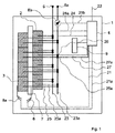
図1には、本発明にしたがうエネルギー蓄積装置1の実施形態について、いくつかの補足的な装置とともに模式的に示す。ここで、制御回線21,21a,21b,22,24,24a,27,27aが破線で示されている。
FIG. 1 schematically illustrates an embodiment of an energy storage device 1 according to the present invention, along with some supplemental devices. Here, the
エネルギー蓄積装置1が、複数の第1のエネルギー蓄積デバイス2と、複数の第2のエネルギー蓄積デバイス3とを有しており、これら蓄積デバイスは、熱伝導を行うような具合に熱伝導装置7に接触している。これらのエネルギー蓄積デバイスは、実質上、直方体状に形成されており、それぞれ、直方体における1つの面(輪郭面)が熱伝導装置7に接している。熱伝導装置にも、第1のエネルギー蓄積デバイス2にも、それぞれ、熱電対8,8aが備えられる。これら熱電対における図示のものは、多数の熱電対、及び、その他の測定装置のうちの代表のみである。これらの熱電対ならびに測定装置は、制御回線21,21aを通じて制御装置4に接続されている。制御装置4には、データ、電流の強さの限界値、動作プロフィル、エラーメッセージなどが保存された記憶装置9が備え付けられている。制御装置4は、接続回線22を通じて、不図示の上位の制御機構に、信号を伝えるように接続されている。各エネルギー蓄積デバイス2,3は、電流ケーブル25,25aを通じて、また出力スイッチ26,26aを通じて、中央の電流回線23,23aに接続されている。これらの出力スイッチ26,26aは、制御装置4により、不図示の制御回線を通じて操作される。中央の電流回線23,23aは、コネクターデバイス6,6aにまで延びており、これらコネクターデバイスは、少なくとも間接的に電力消費部に接続している。多数の電流測定装置は図示していない。これら電流測定装置は、接続ケーブル25,25a中においても電流を検出し、制御装置4に提供するものである。構造様式によっては、これらの電流測定装置が出力スイッチ26,26aと一体に形成されたものでありうる。中央の電流回線23aには、電力消費部に供給される総電流を捉えるべく、中央の電流測定器8bが備えられる。信号回線21bを通じて、中央の電流測定器8bが、制御装置4に少なくとも1つの測定値を与える。制御装置4は、種々の測定装置8,8a,8bの信号を処理し、制御回線27,27aを通じて出力スイッチ26,26aを操作する。好ましくは、これらの出力スイッチ26,26aが、制限された電流の導通を可能にする出力コントローラとして設けられる。
The energy storage device 1 includes a plurality of first
本実施形態において、第2のエネルギー蓄積デバイスは電気化学セルとして構成されている。本実施形態において、第1のエネルギー蓄積デバイスも電気化学セルとして構成されている。第1のエネルギー蓄積デバイス2は、好ましくは、コンデンサまたはコイルとして構成されている。これらのエネルギー密度は、第2のエネルギー蓄積デバイス3のエネルギー密度よりも低い。コイルまたはコンデンサとして構成された第1のエネルギー蓄積デバイス2は、著しく大きい電流を放出し受容することができるという利点がある。エネルギー蓄積装置1が第2のエネルギー蓄積デバイス3だけを有している場合に比べ、上述のような具合により、明らかに高い電流を限られた時間の間だけ電力消費部に供給することができるという利点がある。
In the present embodiment, the second energy storage device is configured as an electrochemical cell. In the present embodiment, the first energy storage device is also configured as an electrochemical cell. The first
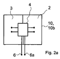
図2(図2a〜図2d)は、本発明にしたがうエネルギー蓄積装置の他の実施形態を示している。この実施形態は、1つの第1のエネルギー蓄積デバイス2と、1つの第2のエネルギー蓄積デバイス3とが1つのハウジング10中に受け入れられて保持されていることを特徴とする。ここで、ハウジング10は、好ましくは、エネルギー蓄積デバイス2,3に接しており、特には熱を伝えるように接している。但し、図面には示していない。特に好ましくは、エネルギー蓄積デバイス2,3が、熱を伝える接触性を向上させるべくハウジング10に押し込まれている。図2のいずれの実施形態においても、制御装置4、または、少なくとも1つの制御部材が備えられる。この制御装置4または制御部材は、他の制御装置または制御部材と、少なくとも、一時的または断続的に信号を交換する。好ましくは、制御装置4と、不図示の出力スイッチまたは出力コントローラとが、一体に設けられる。図2のエネルギー蓄積装置は、事実上、最小単位である。この最小単位を任意の個数だけ互いに組み合わせ、特には電気的に組み合わせて、幾何学的に相互配置することができる。
FIG. 2 (FIGS. 2a-2d) shows another embodiment of an energy storage device according to the present invention. This embodiment is characterized in that one first
図2aは、本発明にしたがうエネルギー蓄積装置についての、さらなる実施形態を示している。この実施形態においては、第1のエネルギー蓄積デバイス2と、第2のエネルギー蓄積デバイス3と、制御装置4と、ハウジング10またはその第2の賦形部材10bと、2つのコネクタークリップまたは端子6,6aとを有している。出力スイッチまたは出力コントローラと、蓋(ふた)として構成されたハウジング10の第1の賦形部材は図示していない。ハウジング10の第2の賦形部材10bは、金属板からなり、エネルギー蓄積デバイス2,3を次のような具合に取り囲む。すなわち、エネルギー蓄積デバイス2,3同士の間に初期応力が加えられるように取り囲む。このようにして、エネルギー蓄積デバイス2,3の輪郭面による熱伝導が改善される。
FIG. 2a shows a further embodiment for an energy storage device according to the present invention. In this embodiment, the first
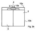
図2bには、図2aの実施形態の側面図を模式的に示す。制御装置4は、図示しない出力コントローラまたは出力スイッチ、及び、コネクター端子6,6aと一体に設けられている。これらの部材はそれぞれ別個に設けることもできる。図示しない出力スイッチまたは出力コントローラは、好ましくは、第2の賦形部材10bと、熱伝導を行うように接続されている。
FIG. 2b schematically shows a side view of the embodiment of FIG. 2a. The
図2cには、図2a及び図2bのエネルギー蓄積装置の実施形態からの変形例について、熱伝導装置7とともに模式的に示す。熱伝導装置7は、エネルギー蓄積デバイス2,3の間に、次のような具合に配置されている。すなわち、熱伝導装置7がハウジング10の第2の賦形部材10bとも熱伝導を行うように接触するように配置されている。また、第2の賦形部材10bは、この中に保持される各デバイスについて、これら相互間に初期応力を加えるような具合に、取り囲んでいる。制御装置4は、図示しない出力コントローラまたは出力スイッチ、及び、コネクタークリップ6,6aと一体に構成されている。図示しない出力スイッチまたは出力コントローラは、好ましくは、第2の賦形部材10bと、熱伝導を行うように接続されている。
FIG. 2 c schematically shows a variation from the embodiment of the energy storage device of FIGS. 2 a and 2 b together with the
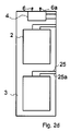
図2dには、本発明にしたがうエネルギー蓄積装置の別の実施形態を示す。エネルギー蓄積デバイス2,3は、重なり合うように配置されている。ハウジング10の第2の賦形部材10bは、第2の賦形部材10bの右側の内面に、その金属壁部に対して電気的に絶縁された図示しない導体条片を有している。この導体条片は、エネルギー蓄積デバイス2,3を互いに導通させる役割を果たす。導体条片は、図示しない出力スイッチまたは出力コントローラを介して、また、制御装置4を介して、コネクタークリップ6,6aにまで導通している。好ましくは、制御装置4と、図示しない出力コントローラとが、1つの共通のアセンブリまたはモジュールにまとめられている。エネルギー蓄積デバイス2,3は、好ましくは、導体条片の側の側面に接続部を備えるように設けられる。図示しない出力スイッチまたは出力コントローラは、好ましくは、第2の賦形部材10bと、熱伝導を行うように接続されている。
FIG. 2d shows another embodiment of an energy storage device according to the present invention. The
Claims (12)
電気化学式またはその他の方式の、1つまたは複数の第2のエネルギー蓄積デバイス(3)とを有し、これらエネルギー蓄積デバイスが、電流の放出と受容のためにそれぞれ設けられており、
1つまたは複数のエネルギー蓄積デバイス(2,3)による電流の放出と受容を制御するように設けられた制御装置(4)と、
各エネルギー蓄積デバイス(2,3)により放出または受容される電流の強さ、またはその他の1つまたは複数の測定値を検出し、この測定値を制御装置(4)へと供給する測定装置(8,8a,8b)とを有するエネルギー蓄積装置(1)において、
1つまたは複数の第2のエネルギー蓄積デバイス(3)のエネルギー密度が、1つまたは複数の第1のエネルギー蓄積デバイス(2)のエネルギー密度よりも高く、
制御装置(4)が、1つまたは複数の検出された電流の強さと、1つまたは複数の予め設定された電流の強さの限界値との差異値を決定し、
制御装置(4)が、1つまたは複数の第1のエネルギー蓄積デバイス(2)について、1つまたは複数の前記差異値に応じて電流を放出させるように制御することを特徴とするエネルギー蓄積装置。 One or more first energy storage devices (2);
One or more second energy storage devices (3) of electrochemical or other type, which are provided for the discharge and reception of currents respectively,
A controller (4) provided to control the discharge and acceptance of current by the one or more energy storage devices (2, 3);
A measuring device that detects the intensity of the current emitted or received by each energy storage device (2, 3) or one or more other measured values and supplies this measured value to the controller (4) In an energy storage device (1) having 8, 8a, 8b)
The energy density of the one or more second energy storage devices (3) is higher than the energy density of the one or more first energy storage devices (2);
The controller (4) determines a difference value between the one or more detected current strengths and the one or more preset current strength limits;
An energy storage device, wherein the control device (4) controls the one or more first energy storage devices (2) to discharge current in accordance with the one or more difference values. .
1つまたは複数の接続装置に接続された接続装置(6,6a)と、
1つまたは複数のエネルギー蓄積装置(2,3)に、熱伝導を行うように接続された熱伝導装置(7)とを有する、請求項1に記載のエネルギー蓄積装置(1)。 A holding device (5) for receiving and holding one or more energy storage devices (2, 3);
A connection device (6, 6a) connected to one or more connection devices;
The energy storage device (1) according to claim 1, comprising a heat conduction device (7) connected to the one or more energy storage devices (2, 3) to conduct heat.
第1のエネルギー蓄積デバイス(2)、第2のエネルギー蓄積デバイス(3)、及び熱伝導装置(7)が、熱伝導を行うように互いに接続されており、第1のエネルギー蓄積デバイス(2)が、熱伝導装置(7)と第2のエネルギー蓄積デバイス(3)との間に配置されていることを特徴とする請求項1または2に記載のエネルギー蓄積装置。 In an energy storage device (1) according to any one of the preceding claims, comprising a heat transfer device (7),
The first energy storage device (2), the second energy storage device (3), and the heat conduction device (7) are connected to each other so as to conduct heat, and the first energy storage device (2) The energy storage device according to claim 1 or 2, characterized in that is arranged between the heat conduction device (7) and the second energy storage device (3).
制御装置(4)が、上位の制御部と1つまたは複数の予め設定された信号を一時的または断続的にに交換し、
データを保存するために設けられた記憶装置(9)が、制御装置(4)に備え付けられていることを特徴とする請求項1〜5のいずれかに記載のエネルギー蓄積装置(1)。 The control device (4) is connected to the upper control unit so as to be able to transmit and receive signals,
The control device (4) exchanges one or more preset signals with the host control unit temporarily or intermittently,
6. The energy storage device (1) according to claim 1, wherein a storage device (9) provided for storing data is provided in the control device (4).
第1のエネルギー蓄積デバイス(2)と第2のエネルギー蓄積デバイス(3)とを取り囲むハウジング(10)を有するものにおいて、
ハウジング(10)が、材料同士の接着、または摩擦での固定により、複数の部分的な領域またはその他でもって、互いに接続された第1の賦形部材(10a)と、熱伝導性の第2の賦形部材(10b)とを有しており、
第2の賦形部材が、エネルギー蓄積装置(2,3)のうちの1つまたは複数と熱伝導を行うように接続されていることを特徴とするエネルギー蓄積装置。 The energy storage device (1) according to any one of claims 1 to 6,
Having a housing (10) surrounding a first energy storage device (2) and a second energy storage device (3);
The housing (10) is connected to the first shaping member (10a) connected to each other in a plurality of partial regions or the like by adhesion between materials or by frictional fixing, and a second thermally conductive material. And a shaping member (10b)
The energy storage device, wherein the second shaping member is connected to conduct heat conduction with one or more of the energy storage devices (2, 3).
1つまたは複数の、カソードとしての電極またはその他の電極が、式LiMPO4の化合物を有しており、ここで、Mは第1列の少なくとも1つの遷移金属カチオンであり、遷移金属カチオンはMn,Fe,Ni,Tiまたはこれらの元素の組み合わせよりなる群から選択されるものであり、前記化合物が、高度のオリビン構造を有していることを特徴とする請求項1〜7のいずれかに記載のエネルギー蓄積装置(1)。 One or more energy storage devices (2, 3) are provided as galvanic cells each with two or more electrodes;
One or more electrodes as cathodes or other electrodes have a compound of formula LiMPO 4 , where M is at least one transition metal cation in the first row, and the transition metal cation is Mn , Fe, Ni, Ti, or a combination of these elements, and the compound has a high degree of olivine structure. The energy storage device (1) described.
セパレータは、非電子伝導性であるかまたは電子伝導性が低く、部分的に物質透過性であるかまたは物質透過性である支持体からなり、
支持体が少なくとも一方の側から無機材料によりコーティングされており、
少なくとも部分的に物質透過性である支持体として、不織布またはその他として構成された有機材料が用いられ、
有機材料は、ポリエチレンテレフタレート(PET)またはその他のポリマー、またはその他のものであり、
有機材料は、−40℃から200℃の温度範囲またはその他の温度範囲でイオン伝導性であるイオン伝導性の無機材料によりコーティングされており、
イオン伝導性の無機材料が、Zr,Al,Liのうちの少なくとも1つについての、酸化物、燐酸塩、硫酸塩、チタン酸塩、珪酸塩、及びアルミノ珪酸塩の群に属する少なくとも1つの化合物、または酸化ジルコン、またはその他であり、
イオン伝導性の無機材料が、最大直径が100nm未満またはその他である粒子を有していることを特徴とする請求項1〜8のいずれかに記載のエネルギー蓄積装置(1)。 At least one energy storage device (2, 3) is configured as a galvanic cell with at least one separator;
The separator consists of a support that is non-electron-conducting or low in electron-conducting, partly material-permeable or material-permeable,
The support is coated with an inorganic material from at least one side;
As a support that is at least partially permeable to matter, an organic material configured as a nonwoven fabric or others is used,
The organic material is polyethylene terephthalate (PET) or other polymer, or others
The organic material is coated with an ion conductive inorganic material that is ion conductive in the temperature range of −40 ° C. to 200 ° C. or other temperature ranges;
At least one compound in which the ion-conductive inorganic material belongs to the group of oxide, phosphate, sulfate, titanate, silicate, and aluminosilicate for at least one of Zr, Al, Li Or zircon oxide, or other,
The energy storage device (1) according to any one of claims 1 to 8, characterized in that the ion-conductive inorganic material has particles whose maximum diameter is less than 100 nm or other.
エネルギー蓄積装置(1)が、
1つまたは複数の第1のエネルギー蓄積デバイス(2)と、
電気化学式またはその他の方式の、1つまたは複数の第2のエネルギー蓄積デバイス(3)とを有し、1つまたは複数の第2のエネルギー蓄積デバイス(3)のエネルギー密度が、1つまたは複数の第1のエネルギー蓄積デバイス(2)のエネルギー密度よりも高く、
1つまたは複数のエネルギー蓄積装置(2,3)による電流の放出と受容を制御するように設けられた制御装置(4)と、
エネルギー蓄積装置(2,3)により放出または受容される電流の強さ、またはその他の、1つまたは複数の測定値を、一時的または断続的に検出し、制御装置(4)へ供給する測定装置(8,8a,8b)とを有しているものにおいて、
制御装置(4)が、1つまたは複数の検出された電流の強さと、1つまたは複数の予め設定された電流の強さの限界値との1つまたは複数の差異値を決定し、
制御装置(4)が、1つまたは複数の前記差異値に応じて、主として1つまたは複数の第1のエネルギー蓄積デバイス(2)を電流の放出のために制御することを特徴とする方法。 A method for operating an energy storage device (1) comprising:
Energy storage device (1)
One or more first energy storage devices (2);
One or more second energy storage devices (3) of the electrochemical or other type, and the energy density of the one or more second energy storage devices (3) is one or more Higher than the energy density of the first energy storage device (2) of
A controller (4) arranged to control the discharge and acceptance of current by one or more energy storage devices (2, 3);
Measurement of the current intensity emitted or received by the energy storage device (2, 3), or other one or more measurements, detected temporarily or intermittently and supplied to the control device (4) Having a device (8, 8a, 8b),
The controller (4) determines one or more difference values between the one or more detected current strengths and the one or more preset current strength limits;
Method according to claim 1, characterized in that the control device (4) mainly controls the one or more first energy storage devices (2) for the discharge of current in response to one or more of the difference values.
制御装置(4)は、検出された電圧またはその他測定値と、1つまたは複数の予め設定された電圧限界値とから1つまたは複数の第2の差異値を決定し、
制御装置(4)が、1つまたは複数の第2の差異値に応じて、主として1つまたは複数の第1のエネルギー蓄積デバイス(2)を電流の放出のために制御し、
制御装置(4)が、1つまたは複数の第2の差異値に応じて、1つまたは複数のエネルギー蓄積装置(2,3)へのエネルギーの供給を遮断することを特徴とする請求項10または11に記載の方法。 The measuring device (8, 8a, 8b) is temporarily or intermittently supplied with one or more energy storage devices while electrical energy is being supplied to the one or more energy storage devices (2, 3). Providing the controller (4) with voltage or other measurements for (2,3);
The control device (4) determines one or more second difference values from the detected voltage or other measured value and the one or more preset voltage limit values;
The controller (4) mainly controls the one or more first energy storage devices (2) for the discharge of current in response to the one or more second difference values;
The control device (4) cuts off the supply of energy to the one or more energy storage devices (2, 3) according to the one or more second difference values. Or the method of 11.
Applications Claiming Priority (3)
| Application Number | Priority Date | Filing Date | Title |
|---|---|---|---|
| DE102009037725A DE102009037725A1 (en) | 2009-08-17 | 2009-08-17 | Energy storage device with an energy storage device |
| DE102009037725.5 | 2009-08-17 | ||
| PCT/EP2010/004650 WO2011020547A1 (en) | 2009-08-17 | 2010-07-29 | Energy storage apparatus comprising an energy storage device |
Publications (2)
| Publication Number | Publication Date |
|---|---|
| JP2013502673A true JP2013502673A (en) | 2013-01-24 |
| JP2013502673A5 JP2013502673A5 (en) | 2013-09-19 |
Family
ID=43088322
Family Applications (1)
| Application Number | Title | Priority Date | Filing Date |
|---|---|---|---|
| JP2012525061A Pending JP2013502673A (en) | 2009-08-17 | 2010-07-29 | Energy storage device comprising an energy storage device |
Country Status (8)
| Country | Link |
|---|---|
| US (1) | US20120176081A1 (en) |
| EP (1) | EP2467896A1 (en) |
| JP (1) | JP2013502673A (en) |
| KR (1) | KR20120083318A (en) |
| CN (1) | CN102484296A (en) |
| BR (1) | BR112012003778A2 (en) |
| DE (1) | DE102009037725A1 (en) |
| WO (1) | WO2011020547A1 (en) |
Cited By (1)
| Publication number | Priority date | Publication date | Assignee | Title |
|---|---|---|---|---|
| WO2014068895A1 (en) * | 2012-10-29 | 2014-05-08 | 三洋電機株式会社 | In-vehicle battery system |
Families Citing this family (4)
| Publication number | Priority date | Publication date | Assignee | Title |
|---|---|---|---|---|
| KR101865235B1 (en) * | 2012-07-09 | 2018-06-07 | 피너지 엘티디. | System and method for controlling operation of a metal-air battery |
| JP5974721B2 (en) * | 2012-08-09 | 2016-08-23 | 株式会社豊田自動織機 | Battery pack |
| EP3346524A1 (en) * | 2017-01-09 | 2018-07-11 | Samsung SDI Co., Ltd | Battery module with thermocouple unit |
| JP6745867B2 (en) * | 2017-12-29 | 2020-08-26 | ゴゴロ インク | System and related methods for managing batteries |
Citations (8)
| Publication number | Priority date | Publication date | Assignee | Title |
|---|---|---|---|---|
| JPH08308103A (en) * | 1995-04-28 | 1996-11-22 | Matsushita Electric Ind Co Ltd | Hybrid power source |
| JP2002281609A (en) * | 2001-03-21 | 2002-09-27 | Masayuki Hattori | Combined secondary battery circuit and regenerative control system |
| JP2005536857A (en) * | 2002-08-24 | 2005-12-02 | デグサ アクチエンゲゼルシャフト | Separator for use in a high energy battery and method for producing the same |
| JP2006187160A (en) * | 2004-12-28 | 2006-07-13 | Sanyo Electric Co Ltd | Hybrid car |
| JP2006296179A (en) * | 2005-03-16 | 2006-10-26 | Macnica Inc | Electricity accumulating device of capacitor and its charging and discharging method |
| JP2008094212A (en) * | 2006-10-11 | 2008-04-24 | Shin Kobe Electric Mach Co Ltd | Battery state detection system |
| JP2009004227A (en) * | 2007-06-21 | 2009-01-08 | Sony Corp | Positive electrode mixture and nonaqueous electrolyte battery |
| JP2009176587A (en) * | 2008-01-25 | 2009-08-06 | Honda Motor Co Ltd | Battery assembly and battery assembly mounting vehicle |
Family Cites Families (14)
| Publication number | Priority date | Publication date | Assignee | Title |
|---|---|---|---|---|
| US4770954A (en) * | 1987-10-16 | 1988-09-13 | Halliburton Company | Switching power supply and method |
| US5825155A (en) * | 1993-08-09 | 1998-10-20 | Kabushiki Kaisha Toshiba | Battery set structure and charge/ discharge control apparatus for lithium-ion battery |
| DE4422231C2 (en) * | 1994-06-24 | 1997-08-28 | Bayerische Motoren Werke Ag | Vehicle electrical system for a motor vehicle |
| JPH11122840A (en) * | 1997-10-13 | 1999-04-30 | Toyota Motor Corp | Secondary battery controller |
| DE19859036A1 (en) * | 1998-12-24 | 2000-06-29 | Audi Ag | Vehicle electrical system for a motor vehicle |
| US20040201365A1 (en) * | 2001-04-05 | 2004-10-14 | Electrovaya Inc. | Energy storage device for loads having variable power rates |
| JP3832417B2 (en) * | 2002-10-22 | 2006-10-11 | 日産自動車株式会社 | Fuel cell system |
| DE102005024777A1 (en) * | 2005-05-31 | 2006-12-07 | Bayerische Motoren Werke Ag | Energy storage device |
| CA2523240C (en) * | 2005-10-11 | 2009-12-08 | Delaware Systems Inc. | Universal battery module and controller therefor |
| US8049465B2 (en) * | 2007-10-10 | 2011-11-01 | Texas Instruments Incorporated | Systems, methods and circuits for determining micro-short |
| JP4893653B2 (en) * | 2008-02-19 | 2012-03-07 | トヨタ自動車株式会社 | Vehicle, rechargeable battery state of charge estimation method and vehicle control method |
| US8421416B2 (en) * | 2008-04-16 | 2013-04-16 | Texas Instruments Incorporated | Battery charge compensation |
| KR101077154B1 (en) * | 2008-04-22 | 2011-10-27 | 한국과학기술원 | Two-Stage Charge Equalization Method and Apparatus for Series-Connected Battery String |
| KR101093597B1 (en) * | 2009-01-30 | 2011-12-15 | 한국과학기술원 | Charge Equalization Apparatus for Series-Connected Battery String Using Regulated Voltage Source |
-
2009
- 2009-08-17 DE DE102009037725A patent/DE102009037725A1/en not_active Withdrawn
-
2010
- 2010-07-29 WO PCT/EP2010/004650 patent/WO2011020547A1/en active Application Filing
- 2010-07-29 KR KR1020127006215A patent/KR20120083318A/en not_active Application Discontinuation
- 2010-07-29 US US13/390,704 patent/US20120176081A1/en not_active Abandoned
- 2010-07-29 EP EP10741917A patent/EP2467896A1/en not_active Withdrawn
- 2010-07-29 BR BR112012003778A patent/BR112012003778A2/en not_active IP Right Cessation
- 2010-07-29 CN CN2010800362661A patent/CN102484296A/en active Pending
- 2010-07-29 JP JP2012525061A patent/JP2013502673A/en active Pending
Patent Citations (8)
| Publication number | Priority date | Publication date | Assignee | Title |
|---|---|---|---|---|
| JPH08308103A (en) * | 1995-04-28 | 1996-11-22 | Matsushita Electric Ind Co Ltd | Hybrid power source |
| JP2002281609A (en) * | 2001-03-21 | 2002-09-27 | Masayuki Hattori | Combined secondary battery circuit and regenerative control system |
| JP2005536857A (en) * | 2002-08-24 | 2005-12-02 | デグサ アクチエンゲゼルシャフト | Separator for use in a high energy battery and method for producing the same |
| JP2006187160A (en) * | 2004-12-28 | 2006-07-13 | Sanyo Electric Co Ltd | Hybrid car |
| JP2006296179A (en) * | 2005-03-16 | 2006-10-26 | Macnica Inc | Electricity accumulating device of capacitor and its charging and discharging method |
| JP2008094212A (en) * | 2006-10-11 | 2008-04-24 | Shin Kobe Electric Mach Co Ltd | Battery state detection system |
| JP2009004227A (en) * | 2007-06-21 | 2009-01-08 | Sony Corp | Positive electrode mixture and nonaqueous electrolyte battery |
| JP2009176587A (en) * | 2008-01-25 | 2009-08-06 | Honda Motor Co Ltd | Battery assembly and battery assembly mounting vehicle |
Cited By (2)
| Publication number | Priority date | Publication date | Assignee | Title |
|---|---|---|---|---|
| WO2014068895A1 (en) * | 2012-10-29 | 2014-05-08 | 三洋電機株式会社 | In-vehicle battery system |
| JPWO2014068895A1 (en) * | 2012-10-29 | 2016-09-08 | 三洋電機株式会社 | In-vehicle battery system |
Also Published As
| Publication number | Publication date |
|---|---|
| WO2011020547A1 (en) | 2011-02-24 |
| DE102009037725A1 (en) | 2011-02-24 |
| KR20120083318A (en) | 2012-07-25 |
| CN102484296A (en) | 2012-05-30 |
| EP2467896A1 (en) | 2012-06-27 |
| BR112012003778A2 (en) | 2016-04-19 |
| US20120176081A1 (en) | 2012-07-12 |
| WO2011020547A8 (en) | 2011-05-12 |
Similar Documents
| Publication | Publication Date | Title |
|---|---|---|
| EP3195445B1 (en) | Systems and methods for fast charging batteries at low temperatures | |
| US10840722B2 (en) | Battery control device | |
| JP5752151B2 (en) | Battery pack system for improving operating performance using internal battery resistance | |
| US20120169297A1 (en) | Secondary battery with a rapid charging capability | |
| US20140335387A1 (en) | Electric storage system | |
| EP2717415A1 (en) | Electricity storage system | |
| WO2012169063A1 (en) | Battery control device and battery system | |
| JP2016091613A (en) | Battery system and soc recovery method | |
| JP3716776B2 (en) | Power system | |
| US20130193927A1 (en) | Electrochemical energy storage device, battery having at least two such electrochemical energy storage devices, and method for operating such an electrochemical energy strorage device | |
| JP2013502673A (en) | Energy storage device comprising an energy storage device | |
| US20160111727A1 (en) | Metal-Ion Battery with Offset Potential Material | |
| US20140272486A1 (en) | Molten salt battery device and control method for molten salt battery device | |
| JP2018142525A (en) | Power storage element and control method for power storage element | |
| JP2013013245A (en) | Power storage system | |
| US20180154756A1 (en) | Method for operating a rechargeable battery cell and battery control device | |
| US10744899B2 (en) | Balancing energy in a parallelized battery system | |
| CN102804477B (en) | Power storage system | |
| WO2007059269B1 (en) | High-rate rechargeable battery | |
| CN110957551A (en) | Battery, in particular lithium ion battery | |
| JP7350701B2 (en) | control system | |
| CN109716149B (en) | Method for operating a battery cell | |
| US20140113168A1 (en) | Frame for an energy storage device, battery cell with the frame and the energy storage device, battery with two of these battery cells and also method for producing the frame | |
| US20130193929A1 (en) | Battery with at least two electrochemical energy converters and method of operating said battery | |
| JP2015220851A (en) | Charging capacity adjusting system and charging capacity adjusting method |
Legal Events
| Date | Code | Title | Description |
|---|---|---|---|
| A521 | Request for written amendment filed |
Free format text: JAPANESE INTERMEDIATE CODE: A523 Effective date: 20130723 |
|
| A621 | Written request for application examination |
Free format text: JAPANESE INTERMEDIATE CODE: A621 Effective date: 20130724 |
|
| A977 | Report on retrieval |
Free format text: JAPANESE INTERMEDIATE CODE: A971007 Effective date: 20140826 |
|
| A131 | Notification of reasons for refusal |
Free format text: JAPANESE INTERMEDIATE CODE: A131 Effective date: 20140902 |
|
| A02 | Decision of refusal |
Free format text: JAPANESE INTERMEDIATE CODE: A02 Effective date: 20150210 |
|
| A521 | Request for written amendment filed |
Free format text: JAPANESE INTERMEDIATE CODE: A821 Effective date: 20150216 |
|
| RD04 | Notification of resignation of power of attorney |
Free format text: JAPANESE INTERMEDIATE CODE: A7424 Effective date: 20150216 |