JP2013253003A - Method and apparatus for producing hydrogen - Google Patents
Method and apparatus for producing hydrogen Download PDFInfo
- Publication number
- JP2013253003A JP2013253003A JP2012130647A JP2012130647A JP2013253003A JP 2013253003 A JP2013253003 A JP 2013253003A JP 2012130647 A JP2012130647 A JP 2012130647A JP 2012130647 A JP2012130647 A JP 2012130647A JP 2013253003 A JP2013253003 A JP 2013253003A
- Authority
- JP
- Japan
- Prior art keywords
- peripheral wall
- water vapor
- reaction
- oxygen
- steam
- Prior art date
- Legal status (The legal status is an assumption and is not a legal conclusion. Google has not performed a legal analysis and makes no representation as to the accuracy of the status listed.)
- Pending
Links
Images

Classifications
-
- C—CHEMISTRY; METALLURGY
- C01—INORGANIC CHEMISTRY
- C01B—NON-METALLIC ELEMENTS; COMPOUNDS THEREOF; METALLOIDS OR COMPOUNDS THEREOF NOT COVERED BY SUBCLASS C01C
- C01B3/00—Hydrogen; Gaseous mixtures containing hydrogen; Separation of hydrogen from mixtures containing it; Purification of hydrogen
- C01B3/02—Production of hydrogen or of gaseous mixtures containing a substantial proportion of hydrogen
- C01B3/32—Production of hydrogen or of gaseous mixtures containing a substantial proportion of hydrogen by reaction of gaseous or liquid organic compounds with gasifying agents, e.g. water, carbon dioxide, air
- C01B3/34—Production of hydrogen or of gaseous mixtures containing a substantial proportion of hydrogen by reaction of gaseous or liquid organic compounds with gasifying agents, e.g. water, carbon dioxide, air by reaction of hydrocarbons with gasifying agents
- C01B3/38—Production of hydrogen or of gaseous mixtures containing a substantial proportion of hydrogen by reaction of gaseous or liquid organic compounds with gasifying agents, e.g. water, carbon dioxide, air by reaction of hydrocarbons with gasifying agents using catalysts
- C01B3/382—Multi-step processes
-
- C—CHEMISTRY; METALLURGY
- C01—INORGANIC CHEMISTRY
- C01B—NON-METALLIC ELEMENTS; COMPOUNDS THEREOF; METALLOIDS OR COMPOUNDS THEREOF NOT COVERED BY SUBCLASS C01C
- C01B3/00—Hydrogen; Gaseous mixtures containing hydrogen; Separation of hydrogen from mixtures containing it; Purification of hydrogen
- C01B3/02—Production of hydrogen or of gaseous mixtures containing a substantial proportion of hydrogen
- C01B3/32—Production of hydrogen or of gaseous mixtures containing a substantial proportion of hydrogen by reaction of gaseous or liquid organic compounds with gasifying agents, e.g. water, carbon dioxide, air
- C01B3/34—Production of hydrogen or of gaseous mixtures containing a substantial proportion of hydrogen by reaction of gaseous or liquid organic compounds with gasifying agents, e.g. water, carbon dioxide, air by reaction of hydrocarbons with gasifying agents
- C01B3/48—Production of hydrogen or of gaseous mixtures containing a substantial proportion of hydrogen by reaction of gaseous or liquid organic compounds with gasifying agents, e.g. water, carbon dioxide, air by reaction of hydrocarbons with gasifying agents followed by reaction of water vapour with carbon monoxide
-
- C—CHEMISTRY; METALLURGY
- C01—INORGANIC CHEMISTRY
- C01B—NON-METALLIC ELEMENTS; COMPOUNDS THEREOF; METALLOIDS OR COMPOUNDS THEREOF NOT COVERED BY SUBCLASS C01C
- C01B2203/00—Integrated processes for the production of hydrogen or synthesis gas
- C01B2203/02—Processes for making hydrogen or synthesis gas
- C01B2203/0205—Processes for making hydrogen or synthesis gas containing a reforming step
- C01B2203/0227—Processes for making hydrogen or synthesis gas containing a reforming step containing a catalytic reforming step
- C01B2203/0244—Processes for making hydrogen or synthesis gas containing a reforming step containing a catalytic reforming step the reforming step being an autothermal reforming step, e.g. secondary reforming processes
-
- C—CHEMISTRY; METALLURGY
- C01—INORGANIC CHEMISTRY
- C01B—NON-METALLIC ELEMENTS; COMPOUNDS THEREOF; METALLOIDS OR COMPOUNDS THEREOF NOT COVERED BY SUBCLASS C01C
- C01B2203/00—Integrated processes for the production of hydrogen or synthesis gas
- C01B2203/02—Processes for making hydrogen or synthesis gas
- C01B2203/0283—Processes for making hydrogen or synthesis gas containing a CO-shift step, i.e. a water gas shift step
- C01B2203/0294—Processes for making hydrogen or synthesis gas containing a CO-shift step, i.e. a water gas shift step containing three or more CO-shift steps
-
- C—CHEMISTRY; METALLURGY
- C01—INORGANIC CHEMISTRY
- C01B—NON-METALLIC ELEMENTS; COMPOUNDS THEREOF; METALLOIDS OR COMPOUNDS THEREOF NOT COVERED BY SUBCLASS C01C
- C01B2203/00—Integrated processes for the production of hydrogen or synthesis gas
- C01B2203/04—Integrated processes for the production of hydrogen or synthesis gas containing a purification step for the hydrogen or the synthesis gas
- C01B2203/042—Purification by adsorption on solids
- C01B2203/043—Regenerative adsorption process in two or more beds, one for adsorption, the other for regeneration
-
- C—CHEMISTRY; METALLURGY
- C01—INORGANIC CHEMISTRY
- C01B—NON-METALLIC ELEMENTS; COMPOUNDS THEREOF; METALLOIDS OR COMPOUNDS THEREOF NOT COVERED BY SUBCLASS C01C
- C01B2203/00—Integrated processes for the production of hydrogen or synthesis gas
- C01B2203/10—Catalysts for performing the hydrogen forming reactions
- C01B2203/1041—Composition of the catalyst
- C01B2203/1047—Group VIII metal catalysts
- C01B2203/1052—Nickel or cobalt catalysts
- C01B2203/1058—Nickel catalysts
-
- C—CHEMISTRY; METALLURGY
- C01—INORGANIC CHEMISTRY
- C01B—NON-METALLIC ELEMENTS; COMPOUNDS THEREOF; METALLOIDS OR COMPOUNDS THEREOF NOT COVERED BY SUBCLASS C01C
- C01B2203/00—Integrated processes for the production of hydrogen or synthesis gas
- C01B2203/10—Catalysts for performing the hydrogen forming reactions
- C01B2203/1041—Composition of the catalyst
- C01B2203/1047—Group VIII metal catalysts
- C01B2203/1064—Platinum group metal catalysts
- C01B2203/107—Platinum catalysts
-
- C—CHEMISTRY; METALLURGY
- C01—INORGANIC CHEMISTRY
- C01B—NON-METALLIC ELEMENTS; COMPOUNDS THEREOF; METALLOIDS OR COMPOUNDS THEREOF NOT COVERED BY SUBCLASS C01C
- C01B2203/00—Integrated processes for the production of hydrogen or synthesis gas
- C01B2203/12—Feeding the process for making hydrogen or synthesis gas
- C01B2203/1205—Composition of the feed
- C01B2203/1211—Organic compounds or organic mixtures used in the process for making hydrogen or synthesis gas
- C01B2203/1235—Hydrocarbons
- C01B2203/1241—Natural gas or methane
-
- C—CHEMISTRY; METALLURGY
- C01—INORGANIC CHEMISTRY
- C01B—NON-METALLIC ELEMENTS; COMPOUNDS THEREOF; METALLOIDS OR COMPOUNDS THEREOF NOT COVERED BY SUBCLASS C01C
- C01B2203/00—Integrated processes for the production of hydrogen or synthesis gas
- C01B2203/12—Feeding the process for making hydrogen or synthesis gas
- C01B2203/1205—Composition of the feed
- C01B2203/1211—Organic compounds or organic mixtures used in the process for making hydrogen or synthesis gas
- C01B2203/1235—Hydrocarbons
- C01B2203/1247—Higher hydrocarbons
Abstract
Description
本発明は、炭化水素を酸素および水蒸気と反応させるオートサーマル改質によって水素を生成する方法と、この方法を実施するのに適した水素の生成装置に関する。 The present invention relates to a method for generating hydrogen by autothermal reforming in which a hydrocarbon reacts with oxygen and steam, and a hydrogen generator suitable for carrying out this method.
水素はクリーンなエネルギーと言われ、水素自動車や燃料電池の燃料として期待されている。さらに、水素は工業的には還元剤として用いられるなど、広い用途を有する。従来、部分酸化反応と水蒸気改質反応を組み合わせたオートサーマル改質により水素を生成する方法が知られている。 Hydrogen is said to be clean energy and is expected as a fuel for hydrogen automobiles and fuel cells. Further, hydrogen has a wide range of uses such as industrially used as a reducing agent. Conventionally, a method of generating hydrogen by autothermal reforming combining a partial oxidation reaction and a steam reforming reaction is known.
メタノールは酸素を含むことから、比較的低い温度でオートサーマル改質工程を実行である(特許文献1参照)。しかし、酸素を含まないメタンのような炭化水素においては、オートサーマル改質工程は例えば700℃で進行されることが示されている(特許文献2参照)。また、用いる触媒を特定のものとする場合でも、炭化水素のオートサーマル改質を進める際の温度は550℃〜650℃程度になることが示されている(特許文献3参照)。 Since methanol contains oxygen, the autothermal reforming step is performed at a relatively low temperature (see Patent Document 1). However, in hydrocarbons such as methane not containing oxygen, it has been shown that the autothermal reforming process proceeds at, for example, 700 ° C. (see Patent Document 2). Further, even when a specific catalyst is used, it has been shown that the temperature at which the autothermal reforming of hydrocarbon proceeds is about 550 ° C. to 650 ° C. (see Patent Document 3).
オートサーマル改質工程を実行するための反応器としては、炭化水素と酸素を含むガスを導入するためのガス導入口と、このガス導入口の下流において炭化水素と酸素との反応領域を形成する周壁とを有するものが用いられている。そのような反応器の材質は、一般的に炭素鋼またはステンレス鋼とされている。 As a reactor for performing the autothermal reforming process, a gas introduction port for introducing a gas containing hydrocarbon and oxygen and a reaction region of hydrocarbon and oxygen are formed downstream of the gas introduction port. What has a surrounding wall is used. The material of such a reactor is generally carbon steel or stainless steel.
一般的な炭素鋼は耐熱温度が400℃以下と言われ、また、一般的なステンレス鋼であるSUS304材でも耐熱温度は700℃以下と言われている。そのため、反応器の材質を一般的な炭素鋼やステンレス鋼として炭化水素のオートサーマル改質工程を実行した場合、炭化水素と酸素との反応である部分酸化反応の際に高熱に曝されることで反応器の寿命が短くなるという問題がある。また、反応器の材質としてクロム、ニッケルの含量が多いSUS310S等の耐熱性に優れたものを採用すると、反応器が高価になるという問題がある。 General carbon steel is said to have a heat resistant temperature of 400 ° C. or lower, and SUS304 material, which is a general stainless steel, is said to have a heat resistant temperature of 700 ° C. or lower. Therefore, when the auto-thermal reforming process of hydrocarbons is performed using general carbon steel or stainless steel as the reactor material, it is exposed to high heat during the partial oxidation reaction, which is a reaction between hydrocarbons and oxygen. There is a problem that the life of the reactor is shortened. Further, if a material having excellent heat resistance such as SUS310S having a high chromium and nickel content is employed as the material of the reactor, there is a problem that the reactor becomes expensive.
そこで、部分酸化反応に際して反応器を外部から冷却することが考えられる。しかし、炭化水素と酸素との反応領域では大きな熱エネルギーが発生する。そのため、反応器を外部から冷却しても、反応領域を形成する周壁の内周面は高熱に曝されるので、耐熱性を十分に向上できないという問題がある。 Therefore, it is conceivable to cool the reactor from the outside during the partial oxidation reaction. However, large thermal energy is generated in the reaction region between hydrocarbon and oxygen. Therefore, even if the reactor is cooled from the outside, the inner peripheral surface of the peripheral wall forming the reaction region is exposed to high heat, so that there is a problem that the heat resistance cannot be sufficiently improved.
本発明は、上記のような従来技術の問題を解決できる水素の生成方法と生成装置を提供することを目的とする。 An object of the present invention is to provide a hydrogen generation method and a generation apparatus that can solve the above-described problems of the prior art.
本発明による水素の生成方法は、炭化水素を酸素および水蒸気と反応器において触媒を用いて反応させるオートサーマル改質工程を有し、前記反応器は、炭化水素および酸素を含むガスを導入するためのガス導入口と、前記ガス導入口の下流において炭化水素と酸素との反応領域を形成する周壁とを有する。本発明方法は、前記オートサーマル改質工程での炭化水素と酸素との反応熱により加熱される前記周壁を冷却するための水蒸気を、前記周壁の内外周面を貫通する水蒸気通路を介して、前記周壁の外部から前記反応領域に導入し、前記オートサーマル改質工程で炭化水素と反応させる水蒸気の少なくとも一部として、前記周壁を冷却した水蒸気を用いることを特徴とする。
本発明によれば、オートサーマル改質工程での炭化水素と酸素との反応熱により加熱される周壁を冷却するための水蒸気を、周壁の内外周面を貫通する水蒸気通路を介して反応領域に導くことができる。これにより、高熱に曝される周壁の内周面側を冷却できるので、反応器の耐熱性を向上できる。さらに、炭化水素と酸素との部分酸化反応での反応熱を、周壁を冷却した水蒸気と炭化水素との水蒸気改質反応により吸収できる。
The method for producing hydrogen according to the present invention includes an autothermal reforming process in which hydrocarbons are reacted with oxygen and steam using a catalyst in a reactor, and the reactor introduces a gas containing hydrocarbons and oxygen. And a peripheral wall that forms a reaction region of hydrocarbon and oxygen downstream of the gas inlet. In the method of the present invention, the steam for cooling the peripheral wall heated by the reaction heat of hydrocarbon and oxygen in the autothermal reforming step is passed through a steam passage that penetrates the inner and outer peripheral surfaces of the peripheral wall. Water vapor that cools the peripheral wall is used as at least part of the water vapor that is introduced into the reaction region from the outside of the peripheral wall and reacts with hydrocarbons in the autothermal reforming step.
According to the present invention, water vapor for cooling the peripheral wall heated by the reaction heat of hydrocarbon and oxygen in the autothermal reforming process is transferred to the reaction region via the water vapor passage penetrating the inner and outer peripheral surfaces of the peripheral wall. Can lead. Thereby, since the internal peripheral surface side of the surrounding wall exposed to high heat can be cooled, the heat resistance of a reactor can be improved. Furthermore, the heat of reaction in the partial oxidation reaction between hydrocarbon and oxygen can be absorbed by the steam reforming reaction between steam and hydrocarbon that have cooled the peripheral wall.
本発明方法においては、前記水蒸気通路を通過する水蒸気とは別の水蒸気を、前記オートサーマル改質工程で炭化水素と反応させる水蒸気として、炭化水素および酸素と共に前記ガス導入口を介して前記反応領域に導入するのが好ましい。
部分酸化反応により生成されるガス温度が高過ぎると触媒活性が低下する。よって、周壁を冷却するために水蒸気通路を通過する水蒸気とは別の水蒸気を、ガス導入口から炭化水素および酸素と共に反応領域に導入することで、部分酸化反応により生成されるガス温度が高くなり過ぎるのを防止しつつ、その水蒸気を水蒸気改質反応に供することができる。
In the method of the present invention, water vapor different from the water vapor passing through the water vapor passage is reacted with hydrocarbons in the autothermal reforming step, and the reaction zone through the gas inlet with hydrocarbons and oxygen. It is preferable to introduce into
If the temperature of the gas produced by the partial oxidation reaction is too high, the catalytic activity is lowered. Therefore, by introducing water vapor different from water vapor passing through the water vapor passage to cool the peripheral wall into the reaction region together with hydrocarbons and oxygen from the gas inlet, the gas temperature generated by the partial oxidation reaction is increased. The steam can be subjected to a steam reforming reaction while preventing the steam from passing.
本発明による水素の生成装置は、炭化水素を酸素および水蒸気と触媒を用いて反応させるオートサーマル改質工程を実行するための反応器を備え、前記反応器は、炭化水素および酸素を含むガスを導入するためのガス導入口と、前記ガス導入口の下流において炭化水素と酸素との反応領域を形成する周壁とを有する。本発明装置は、前記周壁の内外周面を貫通する水蒸気通路を備え、前記オートサーマル改質工程での炭化水素と酸素との反応熱により加熱される前記周壁の冷却用水蒸気の供給源が、前記水蒸気通路に接続され、前記周壁を冷却した水蒸気が、前記オートサーマル改質工程で炭化水素と反応させる水蒸気の少なくとも一部として用いられるように、前記水蒸気通路を介して前記周壁の外部から前記反応領域に導入されることを特徴とする。
本発明装置によれば本発明方法を実施できる。
An apparatus for producing hydrogen according to the present invention includes a reactor for performing an autothermal reforming process in which hydrocarbons are reacted with oxygen and steam using a catalyst, and the reactor contains a gas containing hydrocarbons and oxygen. It has a gas inlet for introduction and a peripheral wall that forms a reaction region of hydrocarbon and oxygen downstream of the gas inlet. The apparatus of the present invention includes a steam passage that penetrates the inner and outer peripheral surfaces of the peripheral wall, and a supply source of steam for cooling the peripheral wall that is heated by reaction heat of hydrocarbon and oxygen in the autothermal reforming step, The steam that is connected to the steam passage and cools the peripheral wall is used as at least part of the steam that reacts with hydrocarbons in the autothermal reforming process, from the outside of the peripheral wall through the steam passage. It is introduced into the reaction zone.
According to the apparatus of the present invention, the method of the present invention can be carried out.
本発明装置において、前記周壁の外周面を覆う空間形成部を備え、前記周壁の外周面に沿った環状領域において、前記周壁の外周面に対向する空間が前記空間形成部により形成され、前記空間と前記反応領域との間において、前記周壁に周方向の間隔をおいて複数の貫通孔が形成され、前記貫通孔により前記水蒸気通路が構成され、前記周壁の冷却用水蒸気の供給源が、前記空間を介して前記水蒸気通路に接続されるのが好ましい。これにより、周壁の冷却用水蒸気を確実に周壁の内周面側に導くことができる。また、周壁を冷却した水蒸気を反応領域の中心に向かい流動させ、反応領域の温度を中心から周壁の内周面に向かうに従い低くし、周壁を効果的に冷却できる。
さらに、前記周壁の一端から前記ガス導入口に向かい延びるカバーが設けられ、前記カバーにおける前記周壁の一端に沿った環状部位に、前記周壁の内周面よりも内方に向かい延びる凹部が形成され、前記凹部と前記反応領域との間において、前記カバーに周方向の間隔をおいて複数の貫通孔が形成され、前記周壁の冷却用水蒸気の供給源が、前記凹部を介して前記カバーに形成された前記貫通孔に接続されるのが好ましい。これによっても、周壁の冷却用水蒸気を周壁の内周面側に導くことができる。
また、前記空間形成部を囲む流路が設けられ、前記流路に、前記空間に導入される水蒸気の冷却用流体が導入されるのが好ましい。これにより、周壁の冷却用水蒸気を冷却用流体により冷却できる。
In the device according to the present invention, the space forming portion that covers the outer peripheral surface of the peripheral wall is provided, and in the annular region along the outer peripheral surface of the peripheral wall, a space facing the outer peripheral surface of the peripheral wall is formed by the space forming portion. And a plurality of through holes are formed in the peripheral wall at circumferential intervals, the water vapor passage is formed by the through holes, and a supply source of steam for cooling the peripheral wall is It is preferable to be connected to the water vapor passage through a space. Thereby, the water vapor | steam for cooling of a surrounding wall can be reliably guide | induced to the inner peripheral surface side of a surrounding wall. Further, the water vapor that has cooled the peripheral wall is caused to flow toward the center of the reaction region, and the temperature of the reaction region is lowered from the center toward the inner peripheral surface of the peripheral wall, thereby effectively cooling the peripheral wall.
Further, a cover extending from one end of the peripheral wall toward the gas introduction port is provided, and a recess extending inward from the inner peripheral surface of the peripheral wall is formed in an annular portion along one end of the peripheral wall in the cover. A plurality of through holes are formed in the cover at circumferential intervals between the recess and the reaction region, and a cooling water supply source for the peripheral wall is formed in the cover through the recess. It is preferable to be connected to the formed through hole. Also by this, the steam for cooling the peripheral wall can be guided to the inner peripheral surface side of the peripheral wall.
In addition, it is preferable that a flow path surrounding the space forming portion is provided, and a water vapor cooling fluid introduced into the space is introduced into the flow path. Thereby, the steam for cooling the peripheral wall can be cooled by the cooling fluid.
本発明の水素の生成方法および生成装置によれば、炭化水素を水および酸素と反応させるオートサーマル改質工程に用いられる反応器の耐熱性を向上し、反応器の材質として高価なものを用いる必要性をなくし、反応器の寿命を延長してコスト低減を図ることができる。 According to the method and apparatus for producing hydrogen of the present invention, the heat resistance of a reactor used in an autothermal reforming process in which a hydrocarbon is reacted with water and oxygen is improved, and an expensive reactor material is used. Costs can be reduced by eliminating the necessity and extending the life of the reactor.
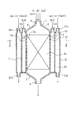
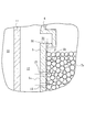
図1〜図3に示す第1実施形態に係る水素の生成装置1は、炭化水素を酸素および水蒸気と反応させるオートサーマル改質工程を実行するための反応器2を備える。本実施形態の反応器2は、上端がガス導入口3とされ、下端がガス流出口4とされ、ガス導入口3とガス流出口4との間に上下方向軸心の円筒状周壁5を有する。
The
周壁5の一端からガス導入口3に向かい延びる上部カバー6が設けられ、上部カバー6にガス導入口3が形成されている。上部カバー6の内径は、ガス導入口3から導入されたガスの流れが拡散するように、ガスの流れの下流に向かうに従い大きくされている。周壁5の他端からガス流出口4に向かい延びる下部カバー7が設けられ、下部カバー7にガス流出口4が形成されている。下部カバー7の内径は、ガス流出口4から流出するガスの流れが絞られるように、ガスの流れの下流に向かうに従い小さくされている。
An
ガス導入口3は、炭化水素および酸素を含むガスと水蒸気を反応器2に導入するために用いられる。炭化水素として、例えばメタンを主成分とする天然ガスやLPG、蒸気状態のガソリン、ナフサ、灯油などが反応領域2aに導入される。酸素は、例えば酸素ガスとして、あるいは空気や酸素富化ガスに含まれる状態で反応領域2aに導入される。炭化水素、酸素、水蒸気はそれぞれ図外供給源から供給され、混合された後にガス導入口3に導かれてもよいし、混合されることなくガス導入口3に導かれてもよい。
The
周壁5は、ガス導入口3の下流において炭化水素と酸素との反応領域2aを形成する。本実施形態の反応領域2aにおいては、炭化水素と水蒸気との反応および一酸化炭素と水蒸気との反応も行われる。すなわち、オートサーマル改質工程は部分酸化反応と水蒸気改質反応の組み合わせであり、例えば炭化水素がメタンである場合、以下の式(1)で示される部分酸化反応と式(2)で示される水蒸気改質反応により水素が生成される。さらに、式(3)で示されるシフト反応がオートサーマル改質工程に含まれる場合がある。発熱反応である部分酸化反応により発生する熱により反応領域2aの温度が一定以上に保持され、その熱が式(2)の吸熱反応である水蒸気改質反応により吸収される。また、シフト反応によっても水素を生成する場合、シフト反応による発生熱も水蒸気改質反応により吸収される。
CH4 +1 /2O2 →CO+2H2 …(1)
CH4 +H2 O→CO+3H2 …(2)
CO+H2 O⇔CO2 +H2 …(3)
The
CH 4 +1/2 O 2 → CO + 2H 2 (1)
CH 4 + H 2 O → CO + 3H 2 (2)
CO + H 2 O⇔CO 2 + H 2 (3)
反応領域2aに、オートサーマル改質工程における反応を促進する触媒が充填される。触媒の種類はオートサーマル改質に適するものであれば特に限定されない。一般的に、白金、パラジウム、ニッケル、ロジウムなどの貴金属触媒を使用でき、特に、ロジウムが好適である。これらの触媒は、一般的に高温でも利用可能であるとされるが、ある温度レベルを超えるとシンタリングを起こすので触媒活性低下の原因になる。そのため、部分酸化反応の最高到達温度は、シンタリングを起こす温度レベル以下に抑えるのが好ましい。部分酸化反応の最高到達温度がシンタリングを起こすレベルよりも高くなることが予想される場合、本実施形態のように炭化水素および酸素と同時に水蒸気もガス導入口3から反応領域2aに導入するのが好ましい。例えば、シンタリングを起こす温度レベルは、白金触媒では約700℃、パラジウム触媒で約600℃、ロジウム触媒で約800℃といわれている。
The
例えば、部分酸化反応に供されるメタン量と水蒸気改質反応に供されるメタン量を等しくし、メタン、酸素、水蒸気を、モル比2.0:0.5:3.0として式(1)〜(3)に従い完全に反応させる場合を考える。この場合、式(1)の部分酸化反応のみが、式(2)の水蒸気改質反応を進行させるのに必要な600℃の温度下で開始されたとすると、部分酸化反応の終了時に生成される反応ガスの温度は820℃となる。そこで触媒活性が低下するのを防止するため、本実施形態のように炭化水素および酸素と同時に水蒸気もガス導入口3から反応領域2aに導入し、部分酸化反応を水蒸気の存在下で行い、部分酸化反応により生成されるガスの温度が高くなり過ぎるのを防止するのが好ましい。
For example, the amount of methane provided for the partial oxidation reaction is equal to the amount of methane provided for the steam reforming reaction, and methane, oxygen, and water vapor are expressed by the formula (1) with a molar ratio of 2.0: 0.5: 3.0. ) To (3) Consider the case of complete reaction. In this case, only the partial oxidation reaction of the formula (1) is generated at the end of the partial oxidation reaction, assuming that it is started at the temperature of 600 ° C. necessary to advance the steam reforming reaction of the formula (2). The temperature of the reaction gas is 820 ° C. Therefore, in order to prevent the catalytic activity from being lowered, water vapor is introduced into the
オートサーマル改質工程において生成された水素を含むガスは、ガス流出口4から流出される。ガス流出口4から流出されるガスから水素を分離するため、ガス流出口4に圧力スイング吸着装置等のガス分離装置を接続すればよい。
The gas containing hydrogen generated in the autothermal reforming process flows out from the
周壁5の外周面5aは、筒状部材により構成される空間形成部11により間隔をおいて覆われている。空間形成部11の上下端は内方に向かい延伸し、延伸端それぞれは上部カバー6と下部カバー7に溶接等により固着されている。これにより、周壁5の外周面5aに沿う環状領域において、周壁の外周面5aに対向する空間12が空間形成部11により形成されている。空間形成部11の上部に、空間12に冷却用水蒸気を導入するための複数の水蒸気導入口11aが設けられ、一方、空間12の下部は閉鎖されている。なお、空間12内から凝縮水を排出するためのドレン配管を設けてもよい。
The outer
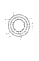
空間12と反応領域2aとの間において、周壁5に複数の貫通孔13が形成されている。本実施形態の貫通孔13は、周方向および軸方向の間隔をおいて形成されている。なお、貫通孔13は少なくとも周方向の間隔をおいて形成されていればよい。貫通孔13の径は、反応領域2aに充填される粒状触媒が周壁5の外部に脱落しないように、触媒の粒径よりも小さくされる。なお、開口13の径を触媒の粒径以上とし、触媒の脱落を防止する金属ネットにより周壁5を覆うようにしてもよい。貫通孔13の径、数、ピッチ、位置は、貫通孔13を通過する冷却用水蒸気が周壁5を冷却できるように実験により定めればよい。本実施形態の貫通孔13は、周壁5の略全域において分布するように形成されるが、部分酸化反応は反応領域2aの上流で主に進行することから、周壁5の上部領域においてのみ分布するように形成してもよい。
A plurality of through
各貫通孔13により、周壁5の内外周面5b、5aを貫通する水蒸気通路が構成されている。水蒸気導入口11cに冷却用水蒸気の供給源(図示省略)が接続されることで、空間12に冷却用水蒸気が導入される。これにより、冷却用水蒸気の供給源が、空間12を介して貫通孔13により構成される水蒸気通路に接続される。その冷却用水蒸気により、オートサーマル改質工程での炭化水素と酸素との反応熱により加熱される周壁5が冷却される。すなわち、図3において破線矢印αで示すように、冷却用水蒸気は周壁5の外周面5a側から内周面5b側に水蒸気通路を介して導かれ、反応領域2aの中心に向かい流動する。これにより、高熱に曝される周壁5の内周面5b側を冷却できる。冷却用水蒸気の温度は、本実施形態では370℃とされるが、部分酸化反応による生成ガスよりも低く、反応器2の材質として一般的に用いられる炭素鋼やステンレス鋼等の耐熱温度に応じて定めればよく、周壁5を500℃以下に冷却できる温度とされるのが好ましい。
Each through
周壁5を冷却した水蒸気は、貫通孔13により構成される水蒸気通路を介して周壁5の外部から反応領域2aに導入されるので、オートサーマル改質工程で炭化水素と反応させる水蒸気の一部として用いられる。これにより、炭化水素と酸素との部分酸化反応での反応熱を、周壁5を冷却した水蒸気と炭化水素との水蒸気改質反応により吸収できる。
The steam that has cooled the
オートサーマル改質工程において効率的に水素を生成するためには、各反応に十分な温度を保った上で、系全体では発熱反応の発熱量と吸熱反応の吸熱量とがバランスするのが好ましい。そのような熱的なバランスをとる上では、部分酸化反応に供されるメタン量を水蒸気改質反応に供されるメタン量よりも多くし、例えば、メタン、酸素、水蒸気のモル比を2.00:0.77:2.46として式(1)〜(3)に従い完全反応させる。なお、水蒸気は完全反応させる場合よりも若干過剰にするのが好ましい。 In order to efficiently generate hydrogen in the autothermal reforming process, it is preferable that the exothermic amount of the exothermic reaction and the endothermic amount of the endothermic reaction are balanced in the entire system while maintaining a sufficient temperature for each reaction. . In order to achieve such a thermal balance, the amount of methane supplied to the partial oxidation reaction is made larger than the amount of methane supplied to the steam reforming reaction, for example, the molar ratio of methane, oxygen, and steam is set to 2. Complete reaction is carried out according to the formulas (1) to (3) as 00: 0.77: 2.46. In addition, it is preferable that the water vapor is slightly excessive as compared with the case of complete reaction.
空間形成部11の外周面は、筒状部材により構成される流路形成部21により覆われている。流路形成部21の上下端は空間形成部11に向かい延伸し、延伸端それぞれが空間形成部11の外周面に溶接等により固着されている。これにより、空間形成部11の外周面に沿う環状領域において、空間形成部11を囲む流路22が流路形成部21により形成されている。流路形成部21の上部に、冷却用流体の図外供給源に接続される複数の流入口21aが形成されている。これにより、空間12に導入される冷却用水蒸気の冷却用流体が、流路22に導入される。流路形成部21の下部に形成される複数の流出口21bから、流路22に導入された冷却用流体が流出する。流出口21bから流出する冷却用流体は、供給源に還流させてもよいし、廃棄してもよい。冷却用流体は、空間12内の水蒸気を冷却できるものであればよく、例えば、空間12内の水蒸気よりも低温の水蒸気、不活性ガス、水等の液体を用いることができ、370℃以下とするのが好ましい。ガス導入口3から酸素を含むガスとして空気を導入し、ガス流出口4に圧力スイング吸着装置等のガス分離装置を接続する場合、ガス分離装置により水素から分離される空気中の窒素を、冷却用流体として用いることができる。冷却用流体として液体を用い、流路22内で蒸発させることで、蒸発熱によっても空間12内の水蒸気を冷却できる。
The outer peripheral surface of the
上記構成の水素の生成装置1を用い、反応器2において炭化水素を酸素および水蒸気と反応させるオートサーマル改質工程を実行すると、反応領域2aの上流部分すなわちガス導入口3に近い部分において、部分酸化反応が主に進行し、水蒸気改質反応とシフト反応が幾分かは進行する。この際、部分酸化反応の反応熱により加熱される周壁5を冷却するための水蒸気が、周壁5の内外周面5b、5aを貫通する水蒸気通路を介し、周壁5の外部から反応領域2aに導入される。これにより、周壁5を冷却した水蒸気を、オートサーマル改質工程で炭化水素と反応させる水蒸気の一部として用いることができる。また、オートサーマル改質工程で炭化水素と反応させる水蒸気として、周壁5を冷却するために水蒸気通路を通過する水蒸気とは別の水蒸気が、炭化水素および酸素と共にガス導入口3を介して反応領域2aに導入される。
When an autothermal reforming process in which the hydrocarbon is reacted with oxygen and water vapor in the
反応領域2aにおいて、部分酸化反応により生成された高温の反応ガスとガス導入口3から導入された水蒸気は、貫通孔13から導入された水蒸気に取り囲まれた状態で、下流に向かい流れる。下流に向かう従い、部分酸化反応により生成されたガスが水蒸気と混合される。これにより、反応領域2aの下流部分においては、水蒸気改質反応とシフト反応が主に進行し、部分酸化反応が幾分かは進行する。水蒸気改質反応の進行により、反応領域2aにおける温度は下流に向かうに従い低下する。反応領域2aの上流部分での部分酸化反応後のガスの流れが下流部分で滞留する時間を確保するため、周壁5に邪魔板等を取り付け、上流部分での発生熱を下流部分での水蒸気改質反応により利用するのが好ましい。また、部分酸化反応により生成されたガスを、貫通孔13から導入された水蒸気とできるだけ均一に混合させるため、ガスの流れを乱流とする邪魔板等を周壁5に取り付けるのが好ましい。
In the
上記実施形態によれば、オートサーマル改質工程での炭化水素と酸素との反応熱により加熱される周壁5を冷却するための水蒸気を、周壁5の外周面5aから内周面5b側に水蒸気通路を介して導くことができる。これにより、高熱に曝される周壁5の内周面5b側を冷却できるので、反応器2の耐熱性を向上できる。さらに、炭化水素と酸素との部分酸化反応での反応熱を、周壁5を冷却した水蒸気と炭化水素との水蒸気改質反応により吸収できる。よって、効率的に水素を生成できると共に、周壁5の材質として一般的な炭素鋼やステンレス鋼等を用いることができる。よって、炭化水素のオートサーマル改質を工業的に実行する上での懸案事項を、周壁5の温度を制御することで解決できる。また、水蒸気通路を通過する水蒸気とは別の水蒸気を、ガス導入口3から炭化水素および酸素と共に反応領域2aに導入することで、部分酸化反応により生成されるガス温度が高くなり過ぎて触媒活性が低下するのを防止しつつ、その水蒸気を水蒸気改質反応に供することができる。さらに、周壁5を冷却した水蒸気を反応領域2aの中心に向かい流動させ、反応領域2aの温度を中心から周壁5の内周面5bに向かうに従い低くし、周壁5を効果的に冷却できる。また、周壁5を冷却する水蒸気を、流路22を流れる流体により冷却できる。
According to the above embodiment, the water vapor for cooling the
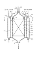
図4〜図6は第2実施形態に係る水素の生成装置1′を示す。以下、第1実施形態との相違点を説明し、同一部分は同一符号で示して説明を省略する。 4 to 6 show a hydrogen generator 1 'according to the second embodiment. Hereinafter, differences from the first embodiment will be described, and the same parts are denoted by the same reference numerals and description thereof will be omitted.
第2実施形態においては、上部カバー6における周壁5の一端に沿った環状部位に、周壁5の内周面5bよりも内方に向かい延びる凹部30が形成されている。凹部30と反応領域2aとの間において、上部カバー6に複数の貫通孔31が周方向の間隔をおいて形成されている。凹部30は空間12に連なるものとされることで、水蒸気導入口11aを介して凹部30に冷却用水蒸気が導入される。これにより冷却用水蒸気の供給源が、凹部30を介して貫通孔31に接続される。その冷却用水蒸気により、オートサーマル改質工程での炭化水素と酸素との反応熱により加熱される周壁5が冷却される。すなわち、図6において破線矢印βで示すように、冷却用水蒸気は周壁5の一端側から内周面5b側に貫通孔31を介して導かれ、周壁5の内周面5bに沿って流動する。これにより、高熱に曝される周壁5の内周面5b側を冷却できる。他は第1実施形態と同様とされる。
In the second embodiment, a
第1実施形態の生成装置1を用いて水素を生成した。反応器2の周壁5は、内径10.4mm、長さ300mmとした。反応領域2aに充填する触媒として、アルミナに担持したロジウム触媒(0.5%Rh/Al2 O3 、NEケムキャット製)を14g用いた。
ガス導入口3から反応領域2aに、予めヒーターにて600℃に加熱したメタン、酸素、水蒸気を、モル比2.00:0.77:2.00、流量1.06L/分で導入した。
冷却用水蒸気として空間12に370℃の水蒸気を88ml/分で導入し、反応領域2aに導入されるメタン、酸素、水蒸気のモル比を、2.00:0.77:2.46よりも水蒸気が若干過剰になるものとした。
流路22に冷却用流体は導入しなかった。
ガス流出口4から流出するガスから残存水蒸気を除去し、ガスクロマトグラフィー(島津製作所GC−TCD)で分析したところ、その組成は水素、一酸化炭素、二酸化炭素であり、モル比は77.8:10.4:11.8であり、生成ガス総流量は2.25L/分であった。反応領域2aの入り口付近での周壁5の温度を測定したところ、500℃以下であった。
Hydrogen was produced | generated using the production |
Methane, oxygen, and water vapor previously heated to 600 ° C. with a heater were introduced from the
As a water vapor for cooling, water at 370 ° C. was introduced into the
The cooling fluid was not introduced into the
The residual water vapor was removed from the gas flowing out from the
空間12への冷却用水蒸気の導入を止め、ガス導入口3からメタン、酸素、水蒸気をモル比2.00:0.77:2.46よりも水蒸気が若干過剰になるものとして、流量1.15L/分で導入した以外は、実施例と同様にして水素を生成した。
ガス流出口4から流出するガスから残存水蒸気を除去し、ガスクロマトグラフィーで分析したところ、その組成は水素、一酸化炭素、二酸化炭素であり、モル比は77.7:10.5:11.8であり、生成ガス総流量は2.23L/分であった。生成ガスの組成、量は実施例と大差なかった。しかし、反応領域2aの入り口付近での周壁5の温度を測定したところ、最大780℃であった。
Assuming that the introduction of steam for cooling into the
When the residual water vapor was removed from the gas flowing out from the
本発明は上記実施形態に限定されない。
例えば、上記各実施形態の反応器2においては、単一の反応領域2aで部分酸化反応、水蒸気改質反応、およびシフト反応が実行されるものとしたが、反応器に部分酸化反応を主に実行するための反応領域、水蒸気改質反応を主に実行するための反応領域、およびシフト反応を主に実行するための反応領域を、個別の周壁を用いて独立して形成してもよい。この場合、部分酸化反応を主に実行するための反応領域を形成する周壁を冷却するために本発明が適用されればよい。また、反応領域毎に充填する触媒の種類を異なるものとしてもよい。例えば、シフト反応を、ルテニウム、パラジウム、ロジウムなどの貴金属系触媒を充填した独立の反応領域で主に実行する場合、反応速度が遅くならないよう300℃以上で実行するため、反応領域を外部から加熱しなければならない場合がある。これに対し、アルミナに銅を担持したCu/Al2 O3 触媒や、銅と酸化亜鉛を担持したCu/ZnO/Al2 O3 触媒等の銅系触媒を充填した独立の反応領域でシフト反応を主に実行する場合、必要な反応温度は260〜300℃であって貴金属系触媒を用いる場合よりも低くてよい。
The present invention is not limited to the above embodiment.
For example, in the
また、耐熱性の高い触媒を用いるような場合、周壁5を冷却した水蒸気をオートサーマル改質工程で炭化水素と反応させる水蒸気の全部とし、ガス導入口3から導入しなくてもよい。要は、周壁5を冷却した水蒸気を、オートサーマル改質工程で炭化水素と反応させる水蒸気の少なくとも一部として用いればよい。
Moreover, when using a catalyst with high heat resistance, the water vapor | steam which cooled the surrounding
1、1′…水素の生成装置、2…反応器、2a…反応領域、3…ガス導入口、5…周壁、5a…外周面、5b…内周面、6…上部カバー、11…空間形成部材、12…空間、13…貫通孔、22…流路、30…凹部、31…貫通孔。
DESCRIPTION OF
Claims (6)
前記反応器は、炭化水素および酸素を含むガスを導入するためのガス導入口と、前記ガス導入口の下流において炭化水素と酸素との反応領域を形成する周壁とを有する水素の生成方法において、
前記オートサーマル改質工程での炭化水素と酸素との反応熱により加熱される前記周壁を冷却するための水蒸気を、前記周壁の内外周面を貫通する水蒸気通路を介して、前記周壁の外部から前記反応領域に導入し、
前記オートサーマル改質工程で炭化水素と反応させる水蒸気の少なくとも一部として、前記周壁を冷却した水蒸気を用いることを特徴とする水素の生成方法。 Having an autothermal reforming process in which hydrocarbons are reacted with oxygen and steam using a catalyst in a reactor;
In the method for producing hydrogen, the reactor includes a gas inlet for introducing a gas containing hydrocarbon and oxygen, and a peripheral wall that forms a reaction region of hydrocarbon and oxygen downstream of the gas inlet.
Steam for cooling the peripheral wall heated by the reaction heat of hydrocarbon and oxygen in the autothermal reforming step is supplied from the outside of the peripheral wall through a steam passage that penetrates the inner and outer peripheral surfaces of the peripheral wall. Introduced into the reaction zone;
A method for producing hydrogen, comprising using, as at least a part of water vapor reacted with hydrocarbons in the autothermal reforming step, water vapor having cooled the peripheral wall.
前記反応器は、炭化水素および酸素を含むガスを導入するためのガス導入口と、前記ガス導入口の下流において炭化水素と酸素との反応領域を形成する周壁とを有する水素の生成装置において、
前記周壁の内外周面を貫通する水蒸気通路を備え、
前記オートサーマル改質工程での炭化水素と酸素との反応熱により加熱される前記周壁の冷却用水蒸気の供給源が、前記水蒸気通路に接続され、
前記周壁を冷却した水蒸気が、前記オートサーマル改質工程で炭化水素と反応させる水蒸気の少なくとも一部として用いられるように、前記水蒸気通路を介して前記周壁の外部から前記反応領域に導入されることを特徴とする水素の生成装置。 A reactor for carrying out an autothermal reforming process in which hydrocarbons are reacted with oxygen and water vapor using a catalyst;
In the hydrogen generator, the reactor includes a gas inlet for introducing a gas containing hydrocarbon and oxygen, and a peripheral wall that forms a reaction region of hydrocarbon and oxygen downstream of the gas inlet.
A water vapor passage penetrating the inner and outer peripheral surfaces of the peripheral wall;
A supply source of steam for cooling the peripheral wall heated by reaction heat between hydrocarbon and oxygen in the autothermal reforming step is connected to the steam passage;
Steam that has cooled the peripheral wall is introduced into the reaction region from the outside of the peripheral wall through the steam passage so that it is used as at least part of the steam that reacts with hydrocarbons in the autothermal reforming step. A hydrogen generator characterized by the above.
前記周壁の外周面に沿った環状領域において、前記周壁の外周面に対向する空間が前記空間形成部により形成され、
前記空間と前記反応領域との間において、前記周壁に周方向の間隔をおいて複数の貫通孔が形成され、
前記貫通孔により前記水蒸気通路が構成され、
前記周壁の冷却用水蒸気の供給源が、前記空間を介して前記水蒸気通路に接続される請求項3に記載の水素の生成装置。 A space forming portion covering the outer peripheral surface of the peripheral wall;
In the annular region along the outer peripheral surface of the peripheral wall, a space facing the outer peripheral surface of the peripheral wall is formed by the space forming portion,
Between the space and the reaction region, a plurality of through holes are formed in the peripheral wall with a circumferential interval,
The water vapor passage is constituted by the through hole,
The hydrogen generating apparatus according to claim 3, wherein a supply source of water vapor for cooling the peripheral wall is connected to the water vapor passage through the space.
前記カバーにおける前記周壁の一端に沿った環状部位に、前記周壁の内周面よりも内方に向かい延びる凹部が形成され、
前記凹部と前記反応領域との間において、前記カバーに周方向の間隔をおいて複数の貫通孔が形成され、
前記周壁の冷却用水蒸気の供給源が、前記凹部を介して前記カバーに形成された前記貫通孔に接続される請求項4に記載の水素の生成装置。 A cover is provided extending from one end of the peripheral wall toward the gas inlet;
A concave portion extending inward from the inner peripheral surface of the peripheral wall is formed in an annular portion along one end of the peripheral wall in the cover,
Between the recess and the reaction region, a plurality of through holes are formed in the cover with a circumferential interval,
The hydrogen generating apparatus according to claim 4, wherein a supply source of water vapor for cooling the peripheral wall is connected to the through hole formed in the cover via the recess.
前記流路に、前記空間に導入される水蒸気の冷却用流体が導入される請求項4または5に記載の水素の生成装置。 A flow path surrounding the space forming portion is provided;
The hydrogen generating apparatus according to claim 4 or 5, wherein a fluid for cooling water vapor introduced into the space is introduced into the flow path.
Priority Applications (4)
| Application Number | Priority Date | Filing Date | Title |
|---|---|---|---|
| JP2012130647A JP2013253003A (en) | 2012-06-08 | 2012-06-08 | Method and apparatus for producing hydrogen |
| KR20147028454A KR20150028223A (en) | 2012-06-08 | 2012-12-17 | Method and apparatus for producing hydrogen |
| PCT/JP2012/082652 WO2013183186A1 (en) | 2012-06-08 | 2012-12-17 | Method and apparatus for producing hydrogen |
| TW101149615A TW201350433A (en) | 2012-06-08 | 2012-12-24 | Method and apparatus for producing hydrogen |
Applications Claiming Priority (1)
| Application Number | Priority Date | Filing Date | Title |
|---|---|---|---|
| JP2012130647A JP2013253003A (en) | 2012-06-08 | 2012-06-08 | Method and apparatus for producing hydrogen |
Publications (1)
| Publication Number | Publication Date |
|---|---|
| JP2013253003A true JP2013253003A (en) | 2013-12-19 |
Family
ID=49711597
Family Applications (1)
| Application Number | Title | Priority Date | Filing Date |
|---|---|---|---|
| JP2012130647A Pending JP2013253003A (en) | 2012-06-08 | 2012-06-08 | Method and apparatus for producing hydrogen |
Country Status (4)
| Country | Link |
|---|---|
| JP (1) | JP2013253003A (en) |
| KR (1) | KR20150028223A (en) |
| TW (1) | TW201350433A (en) |
| WO (1) | WO2013183186A1 (en) |
Families Citing this family (1)
| Publication number | Priority date | Publication date | Assignee | Title |
|---|---|---|---|---|
| CN111692885A (en) * | 2020-06-24 | 2020-09-22 | 广州汤姆逊电气有限公司 | Integrative mutual inductance three-purpose heating function furnace of high temperature pouring |
Citations (3)
| Publication number | Priority date | Publication date | Assignee | Title |
|---|---|---|---|---|
| JP2000203802A (en) * | 1999-01-13 | 2000-07-25 | Toyota Motor Corp | Reformer |
| JP2001139303A (en) * | 1999-11-04 | 2001-05-22 | Hitachi Ltd | Method and device for producing hydrogen/carbon monoxide mixed gas, and fuel/power combination plant provided with the device |
| JP2003123819A (en) * | 2001-10-10 | 2003-04-25 | Babcock Hitachi Kk | Hydrogen generating device for fuel cell |
-
2012
- 2012-06-08 JP JP2012130647A patent/JP2013253003A/en active Pending
- 2012-12-17 WO PCT/JP2012/082652 patent/WO2013183186A1/en active Application Filing
- 2012-12-17 KR KR20147028454A patent/KR20150028223A/en not_active Application Discontinuation
- 2012-12-24 TW TW101149615A patent/TW201350433A/en unknown
Patent Citations (3)
| Publication number | Priority date | Publication date | Assignee | Title |
|---|---|---|---|---|
| JP2000203802A (en) * | 1999-01-13 | 2000-07-25 | Toyota Motor Corp | Reformer |
| JP2001139303A (en) * | 1999-11-04 | 2001-05-22 | Hitachi Ltd | Method and device for producing hydrogen/carbon monoxide mixed gas, and fuel/power combination plant provided with the device |
| JP2003123819A (en) * | 2001-10-10 | 2003-04-25 | Babcock Hitachi Kk | Hydrogen generating device for fuel cell |
Also Published As
| Publication number | Publication date |
|---|---|
| KR20150028223A (en) | 2015-03-13 |
| WO2013183186A1 (en) | 2013-12-12 |
| TW201350433A (en) | 2013-12-16 |
Similar Documents
| Publication | Publication Date | Title |
|---|---|---|
| JP7261235B2 (en) | System and method for synthesis gas production | |
| JP5015638B2 (en) | Permselective membrane reactor and hydrogen production method | |
| CA2641183A1 (en) | Oxygen removal | |
| AU2005289675B2 (en) | Apparatus and method for preferential oxidation of carbon monoxide | |
| KR20200096755A (en) | Methods and systems for synthesis gas production | |
| JPWO2007105696A1 (en) | Hydrogen production apparatus and hydrogen production method | |
| CA2786519C (en) | Apparatus and method for adiabatic methane conversion | |
| JP2021505515A (en) | Methods and equipment for reforming hydrocarbon gases | |
| CA2651336A1 (en) | A reactor device, and a method for carrying out a reaction with hydrogen as reaction product | |
| KR20190016515A (en) | CO hatching syngas production | |
| JP2020075829A (en) | Reforming apparatus, producing method of reformed gas, and reforming system | |
| WO2013183186A1 (en) | Method and apparatus for producing hydrogen | |
| JPWO2008149900A1 (en) | Method for producing hydrogen and reforming reactor | |
| JP2011195393A (en) | Membrane separation type reactor, membrane separation type hydrogen production apparatus and method for producing hydrogen | |
| EP3720813B1 (en) | System and process for production of synthesis gas | |
| GB2423489A (en) | Water gas shift reactor | |
| US9976811B2 (en) | Spiral heat exchanger for hydrodesulfurizer feedstock | |
| EA040289B1 (en) | SYSTEM AND METHOD FOR PRODUCING SYNTHESIS GAS | |
| AU2011204498B2 (en) | Apparatus and method for adiabatic methane conversion | |
| JP2011251865A (en) | Ammonia synthesizer | |
| JP2005231965A (en) | Carbon monoxide stripping device and fuel cell generating set | |
| JP2008222501A (en) | Co selective oxidation method and co selective oxidation reactor |
Legal Events
| Date | Code | Title | Description |
|---|---|---|---|
| A621 | Written request for application examination |
Free format text: JAPANESE INTERMEDIATE CODE: A621 Effective date: 20150205 |
|
| A131 | Notification of reasons for refusal |
Free format text: JAPANESE INTERMEDIATE CODE: A131 Effective date: 20151111 |
|
| A02 | Decision of refusal |
Free format text: JAPANESE INTERMEDIATE CODE: A02 Effective date: 20160309 |