JP2013244162A - Ultrasonograph - Google Patents
Ultrasonograph Download PDFInfo
- Publication number
- JP2013244162A JP2013244162A JP2012119579A JP2012119579A JP2013244162A JP 2013244162 A JP2013244162 A JP 2013244162A JP 2012119579 A JP2012119579 A JP 2012119579A JP 2012119579 A JP2012119579 A JP 2012119579A JP 2013244162 A JP2013244162 A JP 2013244162A
- Authority
- JP
- Japan
- Prior art keywords
- region
- transmission
- unit
- reception
- ultrasonic
- Prior art date
- Legal status (The legal status is an assumption and is not a legal conclusion. Google has not performed a legal analysis and makes no representation as to the accuracy of the status listed.)
- Pending
Links
Images


Abstract
Description
本発明は、Bモード画像内に設定された着目領域の音速マップを生成する超音波診断装置に関する。 The present invention relates to an ultrasonic diagnostic apparatus that generates a sound speed map of a region of interest set in a B-mode image.
医療分野では、被検体の内部を観察して診断を行うために超音波診断装置がよく用いられている。超音波診断装置は、超音波の送受信を行う超音波探触子(プローブ)を有しており、超音波プローブから被検体内に向けて超音波を送信し、被検体内で反射された超音波を超音波探触子で受信することで、この受信信号に基づきBモード画像を生成することができる。Bモード画像は、超音波エコーの振幅を点の明るさ(輝度)により表した画像である。このBモード画像により、被検体内に存在する構造物(例えば、内臓や病変組織等)の輪郭を観察することができる。 In the medical field, an ultrasonic diagnostic apparatus is often used to make a diagnosis by observing the inside of a subject. The ultrasonic diagnostic apparatus has an ultrasonic probe (probe) that transmits and receives ultrasonic waves, transmits ultrasonic waves from the ultrasonic probe into the subject, and reflects the ultrasonic waves reflected in the subject. By receiving the sound wave with the ultrasonic probe, a B-mode image can be generated based on the received signal. The B-mode image is an image representing the amplitude of the ultrasonic echo by the brightness (luminance) of the point. With this B-mode image, it is possible to observe the outline of a structure (for example, a viscera or a diseased tissue) existing in the subject.
近年、被検体内の診断部位を精度よく診断するために、Bモード画像上で医師が指定した着目領域(診断部位)における局所音速を測定し、この着目領域における音速分布を表す音速マップを生成して、Bモード画像に重畳して表示している。このような着目領域における局所音速を測定する方法は例えば特許文献1に開示されている。
In recent years, in order to accurately diagnose a diagnostic region within a subject, a local sound velocity in a region of interest (diagnostic region) designated by a doctor on a B-mode image is measured, and a sound velocity map representing a sound velocity distribution in this region of interest is generated. Then, it is displayed superimposed on the B-mode image. A method for measuring the local sound velocity in such a region of interest is disclosed in
特許文献1記載の局所音速の算出方法では、着目領域の格子点XROIと超音波探触子との間に複数の格子点A1,A2,…を設定して、各格子点(XROI、A1,A2,…)における最適音速値を判定する。ここで、最適音速値とは、画像のコントラスト値、シャープネス値が最も高くなる音速値である。次いで、各格子点における最適音速値に基づいて、格子点XROIにおける局所音速を求める。具体的には、ホイヘンスの原理により、格子点XROIからの受信波と、格子点A1,A2,…からの受信波を仮想的に合成した受信波とが一致することを利用する(図11参照)。これにより、局所音速を正確に測定することができるので、高精度な音速マップが得られる。
The method of calculating the local sound velocity of the
ところで、着目領域内において、血管や動きの大きい組織(臓器)などの構造物が存在する領域は、上述の音速計算を画像のコントラスト値やシャープネス値に基づいて行う関係上、音速誤差が生じやすい。その結果、音速計算の計算結果の信頼性が十分に得られず、血管等の構造物の影響を強く受けた音速マップが生成されてしまう。 By the way, in a region where a structure such as a blood vessel or a tissue (organ) having a large movement exists in the region of interest, a sound speed error is likely to occur because the sound speed calculation described above is performed based on the contrast value or sharpness value of the image. . As a result, the reliability of the calculation result of the sound speed calculation is not sufficiently obtained, and a sound speed map that is strongly influenced by a structure such as a blood vessel is generated.
特許文献2には、着目領域から血管等の構造物を除いた領域における弾性画像を生成する超音波診断装置が開示されている。この特許文献2の超音波診断装置では、着目領域内の歪み分布を求めるとともに、超音波の受信信号から血管内の血流等に起因するドプラ信号を抽出して、このドプラ信号に基づき血流の流速等を示すドプラデータを生成する。次いで、先に求めた歪み分布の中から、ドプラーデータに基づき所定の流速以上となっている部分の歪みを除外した歪み分布に基づき、弾性画像を生成している。また、特許文献3にも、弾性画像データから血流領域を検出して除去する旨が開示されている。このため、特許文献2及び3の記載に基づき、着目領域の局所音速の分布を求めるとともに、着目領域のドプラデータを生成して、このドプラデータに基づいて着目領域から血管等の構造物を除いた領域の局所音速値に基づいて音速マップを生成する方法も提案されている。
しかしながら、着目領域内の各点の局所音速値の算出に加えてドプラデータの生成まで行う場合には膨大な演算処理を要するので、音速マップの生成に時間がかかるという問題が生じる。また、音速マップの生成時間を短縮するためには、高性能な演算処理装置(CPU)を超音波診断装置に搭載する必要があるので、超音波診断装置の製造コストが増加するという問題が生じる。 However, in the case where the generation of Doppler data is performed in addition to the calculation of the local sound velocity value at each point in the region of interest, a problem arises in that it takes time to generate the sound velocity map because enormous calculation processing is required. Further, in order to shorten the generation time of the sound velocity map, it is necessary to mount a high-performance arithmetic processing unit (CPU) in the ultrasonic diagnostic apparatus, which causes a problem that the manufacturing cost of the ultrasonic diagnostic apparatus increases. .
本発明の目的は、血管等の構造物の影響を極力抑えた音速マップの生成を短時間で行うことができる超音波診断装置を提供することにある。 An object of the present invention is to provide an ultrasonic diagnostic apparatus capable of generating a sound velocity map that suppresses the influence of structures such as blood vessels as much as possible in a short time.
本発明の目的を達成するための超音波診断装置は、超音波を被検体に送信し、かつ被検体によって反射された超音波を受信して超音波検出信号を出力する複数の素子を含む超音波探触子と、複数の素子をそれぞれ駆動する複数の駆動信号を複数の素子に供給し、かつ複数の素子から出力された超音波検出信号に基づき受信データを生成する送受信部であって、複数の素子に供給する複数の駆動信号の遅延量を調節することで超音波ビームを形成する送受信部と、被検体内に着目領域を設定する着目領域設定部と、送受信部を制御して、着目領域内の移動体の情報を得るための超音波の送受信を複数の素子に実行させる第1の送受信制御部と、移動体の情報を得るための超音波の送受信がなされたときに、移動体によりドプラ偏移されて反射された超音波の超音波検出信号に基づいて送受信部が生成した受信データから、移動体の動きに伴うドプラ信号を抽出して、この抽出結果に基づき着目領域内の移動体を含む移動体領域を判別する移動体領域判別部と、移動体領域判別部の判別結果に基づき、着目領域の中から移動体領域を除いた領域を、音速の分布を測定する音速測定領域として決定する音速測定領域決定部と、音速測定領域内に超音波ビームの送信焦点を複数設定し、各送信焦点に対する超音波ビームの送受信を送受信部に行わせることで、音速測定領域の音速測定用の受信データを送受信部に生成させる第2の送受信制御部と、音速測定用の受信データに基づき音速測定領域の音速の分布を示す音速マップを生成する音速マップ生成部と、を備えることを特徴とする。 An ultrasonic diagnostic apparatus for achieving an object of the present invention includes an ultrasonic device that includes a plurality of elements that transmit ultrasonic waves to a subject, receive ultrasonic waves reflected by the subject, and output ultrasonic detection signals. A transmission / reception unit for supplying a plurality of drive signals for driving the acoustic probe and the plurality of elements to the plurality of elements and generating reception data based on the ultrasonic detection signals output from the plurality of elements, A transmission / reception unit that forms an ultrasonic beam by adjusting delay amounts of a plurality of drive signals supplied to a plurality of elements, a region of interest setting unit that sets a region of interest in a subject, and a transmission / reception unit, A first transmission / reception control unit that causes a plurality of elements to perform transmission / reception of ultrasonic waves for obtaining information on a moving body within a region of interest, and movement when ultrasonic transmission / reception for obtaining information on the moving body is performed. Reflected by the Doppler shift by the body The Doppler signal accompanying the movement of the moving object is extracted from the received data generated by the transmitting / receiving unit based on the ultrasonic detection signal of the ultrasonic wave, and the moving object region including the moving object in the region of interest is extracted based on the extraction result. Based on the discrimination results of the moving body area discriminating section and the moving body area discriminating section, the area excluding the moving body area from the area of interest is determined as the sound speed measuring area for measuring the sound velocity distribution. And a plurality of ultrasonic beam transmission focal points in the sound velocity measurement area, and the transmission / reception unit transmits / receives ultrasonic beams to / from each transmission focal point, thereby transmitting / receiving reception data for sound velocity measurement in the sound velocity measurement area And a sound speed map generating unit that generates a sound speed map indicating a sound speed distribution in the sound speed measurement region based on reception data for sound speed measurement.
本発明によれば、着目領域の中から音速誤差が生じやすい移動体領域を除いた音速測定領域の音速マップを生成することができる。 According to the present invention, it is possible to generate a sound speed map of a sound speed measurement region excluding a moving body region in which a sound speed error is likely to occur from a region of interest.
送受信部を制御して、被検体内の断層像情報を得るための超音波の送受信を複数の素子に実行させる第3の送受信制御部と、断層像情報を得るための超音波の送受信がなされたときに送受信部が生成した受信データに基づきBモード画像を生成する画像生成部と、Bモード画像を表示する表示部と、を備え、着目領域設定部は、Bモード画像上に着目領域を設定することが好ましい。Bモード画像を見ながら着目領域を設定することができる。 A transmission / reception unit is controlled to transmit / receive ultrasonic waves for obtaining tomographic image information in the subject to a plurality of elements, and transmission / reception of ultrasonic waves for obtaining tomographic image information is performed. An image generation unit that generates a B-mode image based on the reception data generated by the transmission / reception unit, and a display unit that displays the B-mode image, and the attention area setting unit displays the attention area on the B-mode image. It is preferable to set. A region of interest can be set while viewing a B-mode image.
第1の送受信制御部による送受信部の制御と、移動体領域判別部による移動体領域の判別と、音速測定領域決定部による音速測定領域の決定と、第2の送受信制御部による送受信部の制御と、音速マップ生成部による音速マップの生成と、を含む音速マップ更新処理を実行させる更新制御部を備えることが好ましい。音速マップを再度生成する前に、移動体領域の判別や音速測定領域の決定を再度行うので、血管(血流)や動きの大きい組織等の各種移動体の影響を受けない音速マップを再生成(更新処理)することができる。 Control of the transmission / reception unit by the first transmission / reception control unit, determination of the moving body region by the mobile body region determination unit, determination of the sound velocity measurement region by the sound velocity measurement region determination unit, and control of the transmission / reception unit by the second transmission / reception control unit And an update control unit that executes a sound speed map update process including generation of a sound speed map by the sound speed map generation unit. Before regenerating the sound velocity map, the moving object region is determined and the sound velocity measurement region is determined again, so the sound velocity map that is not affected by various moving objects such as blood vessels (blood flow) and tissues with large movements is regenerated. (Update process).
更新制御部は、予め定められたフレーム数のBモード画像が画像生成部により生成される毎に、音速マップ更新処理を実行させることが好ましい。音速マップを定期的に更新することができる。 It is preferable that the update control unit execute the sound velocity map update process each time a B-mode image having a predetermined number of frames is generated by the image generation unit. The sound speed map can be updated periodically.
移動体には、着目領域内の血管を流れる血液が含まれており、移動体領域判別部は、ドプラ信号の抽出結果に基づき、着目領域内での血液の流れを示す血流情報を生成して、血流情報に基づき移動体領域を判別することが好ましい。血管(血流)の影響を受けない音速マップを生成することができる。 The moving body includes blood flowing through the blood vessel in the region of interest, and the moving body region determination unit generates blood flow information indicating the blood flow in the region of interest based on the extraction result of the Doppler signal. Thus, it is preferable to determine the moving body region based on the blood flow information. A sound velocity map that is not affected by blood vessels (blood flow) can be generated.
移動体には、着目領域内で移動する組織が含まれており、移動体領域判別部は、ドプラ信号の抽出結果に基づき、着目領域内での組織の移動を示す組織移動情報を生成して、組織移動情報に基づき移動体領域を判別することが好ましい。移動する組織の影響を受けない音速マップを生成することができる。 The moving body includes a tissue that moves within the region of interest, and the moving body region determination unit generates tissue movement information indicating the movement of the tissue within the region of interest based on the extraction result of the Doppler signal. It is preferable to determine the moving body region based on the tissue movement information. A sound velocity map that is not affected by the moving tissue can be generated.
移動体領域判別部は、送受信部が生成した受信データから、組織の中で動きの大きさが予め定めたしきい値以上となる組織に対応するドプラ信号を抽出して、ドプラ信号に基づき組織移動情報を生成することが好ましい。組織の中でも動きの大きい組織の影響を受けない音速マップを生成することができる。 The moving body region discriminating unit extracts a Doppler signal corresponding to a tissue whose magnitude of movement is greater than or equal to a predetermined threshold in the tissue from the reception data generated by the transmitting / receiving unit, and based on the Doppler signal It is preferable to generate movement information. It is possible to generate a sound velocity map that is not affected by a large-motion organization.
表示部は、Bモード画像上に音速マップを重畳表示することが好ましい。 The display unit preferably superimposes and displays a sound velocity map on the B-mode image.
本発明の超音波診断装置は、Bモード画像上に設定された着目領域の中から移動体を含む移動体領域を除いた領域を音速測定領域として決定し、この音速測定領域の局所音速値を求めて音速マップを生成するので、着目領域内の全領域で局所音速値を求める必要が無くなる。その結果、音速マップの生成の際における演算処理を従来よりも低減させることができるので、血管(血流)や動きの大きい組織等の各種移動体の影響を受けない音速マップを従来よりも短時間で生成することができる。 The ultrasonic diagnostic apparatus of the present invention determines a region excluding a moving body region including a moving body from a region of interest set on a B-mode image as a sound speed measurement region, and determines a local sound speed value of the sound speed measurement region. Since the sound velocity map is generated by the determination, it is not necessary to determine the local sound velocity value in the entire region within the region of interest. As a result, it is possible to reduce the calculation processing at the time of generating the sound velocity map as compared with the conventional case, so that the sound velocity map which is not affected by various moving bodies such as blood vessels (blood flow) and tissues with large movements is shorter than before. Can be generated in time.
[第1実施形態の超音波診断装置の装置構成]
図1に示すように、超音波診断装置10は、超音波探触子300から被検体OBJ(図10参照)に超音波ビームを送信して、被検体OBJによって反射された超音波ビーム(超音波エコー)を受信して得られた超音波検出信号から超音波画像を作成・表示する装置である。超音波診断装置10は、大別して、CPU100、格納部102、表示部104、表示制御部105、操作入力部(着目領域設定部)200、超音波探触子300、送受信部400、画像信号生成部(画像生成部)500、再生部600、データ解析計測部700、ドプラ信号処理部(移動体領域判別部)701、音速測定領域決定部702を備えている。
[Apparatus Configuration of Ultrasonic Diagnostic Apparatus of First Embodiment]
As shown in FIG. 1, the ultrasonic diagnostic apparatus 10 transmits an ultrasonic beam from an
CPU(Central Processing Unit:中央処理装置)100は、操作入力部200からの操作入力に応じて超音波診断装置10の各ブロックの制御を行う。
A CPU (Central Processing Unit) 100 controls each block of the ultrasound diagnostic apparatus 10 in accordance with an operation input from the
操作入力部200は、オペレータからの操作入力を受け付ける入力デバイスであり、操作卓202とポインティングデバイス204とを含んでいる。操作卓202は、文字情報(例えば、患者情報)の入力を受け付けるキーボードと、表示モードを切り替える表示モード切り替えボタンと、ライブモードとフリーズモードとの切り替えを指示するためのフリーズボタンと、シネメモリ再生を指示するためのシネメモリ再生ボタンと、超音波画像の解析・計測を指示するための解析・計測ボタンとを含んでいる。
The
表示モードには、Bモード画像を単独で表示するモードや、Bモード画像と、局所音速の分布を示す音速マップまたは血流や組織などの移動速度を示すカラーフローマッピング像とを表示するモードなどが含まれている。 The display mode includes a mode for displaying a B-mode image alone, a mode for displaying a B-mode image, a sound speed map indicating a distribution of local sound speeds, or a color flow mapping image indicating a moving speed of blood flow, tissue, and the like. It is included.
ポインティングデバイス204は、表示部104の画面上における領域の指定の入力を受け付けるデバイスであり、例えば、トラックボール又はマウスである。ポインティングデバイス204は、Bモード画像上での着目領域(ROI:Region of Interest、関心領域ともいう)の設定に用いられる。なお、ポインティングデバイス204としては、タッチパネルを用いることも可能である。
The
格納部102は、CPU100により超音波診断装置10の各ブロックの制御を制御するための制御プログラム、パラメータを格納する記憶装置であり、例えば、ハードディスク又は半導体メモリである。
The
表示部104は、例えば、CRT(Cathode Ray Tube)ディスプレイ又は液晶ディスプレイであり、超音波画像(動画及び静止画)の表示、音速マップ、カラーフローマッピング像及び各種の設定画面などを表示する。表示制御部105は、画像信号生成部500から出力された画像データに基づき表示部104に超音波画像等を表示させる。
The
超音波探触子300は、被検体OBJに当接させて用いるプローブであり、1次元又は2次元の超音波トランスデューサアレイを構成する複数の素子302を備えている。各素子302は、送受信部400から印加される駆動信号に基づいて超音波ビームを被検体OBJに送信するとともに、被検体OBJから反射される超音波エコーを受信して検出信号を出力する。
The
各素子302は、圧電性を有する材料(圧電体)の両端に電極が形成されて構成された振動子を含んでいる。振動子を構成する圧電体としては、例えば、PZT(チタン酸ジルコン酸鉛:Pb (lead) zirconate titanate)のような圧電セラミック、PVDF(ポリフッ化ビニリデン:polyvinylidene difluoride)のような高分子圧電素子を用いることができる。振動子の電極に電気信号を送って電圧を印加すると圧電体が伸縮し、この圧電体の伸縮により各振動子において超音波が発生する。例えば、振動子の電極にパルス状の電気信号を送るとパルス状の超音波が発生し、振動子の電極に連続波の電気信号を送ると連続波の超音波が発生する。そして、各振動子において発生した超音波が合成されて超音波ビームが形成される。また、各振動子により超音波が受信されると、各振動子の圧電体が伸縮して電気信号を発生する。各振動子において発生した電気信号は、超音波検出信号として送受信部400に出力される。
Each
なお、素子302としては、超音波変換方式の異なる複数種類の素子を用いることも可能である。例えば、超音波を送信する素子として上述の圧電体により構成される振動子を用いて、超音波を受信する素子として光検出方式の超音波トランスデューサを用いるようにしてもよい。ここで、光検出方式の超音波トランスデューサとは、超音波信号を光信号に変換して検出するものであり、例えば、ファブリーペロー共振器又はファイバブラッググレーティングである。
As the
送受信部400は、超音波の送受信制御を行うものであり、送信回路402、受信回路404、及びA/D変換器406を備えている。送信回路402は、駆動信号をそれぞれ各素子302に送る。受信回路404は、各素子302から入力される検出信号を受信して音線信号を生成する。A/D変換器406は、アナログの音線信号をデジタル信号(RFデータ)に変換する。
The transmission /
画像信号生成部500は、送受信部400から入力されるRFデータに基づき、表示用の画像データ(例えばBモード画像データ)を生成するものであり、信号処理部502、DSC(Digital Scan Converter)504、画像処理部506、画像メモリ508、D/A変換器510を備えている。信号処理部502は、RFデータに基づきBモード画像データを生成する。DSC504は、Bモード画像データ等をテレビジョン信号の走査方式の画像データに変換する。画像処理部506は、画像データに各種の画像処理を施す。画像メモリ508は、画像処理後の画像データを一時的に格納する。D/A変換器510は、デジタルの画像データをアナログの画像信号に変換する。
The image
再生部600は、後述のシネメモリ再生モード時に作動するものであり、シネメモリ602とシネメモリ再生部604とを有している。シネメモリ602は、A/D変換器406に接続しており、A/D変換器406から入力されたRFデータを格納する。シネメモリ再生部604は、シネメモリ602に格納されているRFデータを信号処理部502に送る。
The
データ解析計測部700は、RFデータを用いてオペレータ指定の解析・計測を行う。ドプラ信号処理部701は、RFデータに基づきカラードプライメージング(血流イメージング、組織ドプライメージング)用、すなわち、被検体OBJ内の血流や組織の移動状態を表すカラードプラ情報を生成する。さらに、ドプラ信号処理部701は、カラードプラ情報からカラーフローマッピング像(カラードプラ断層像ともいう、以下、「CFM像」と略す)を生成する。音速測定領域決定部702は、音速マップ生成の際に、着目領域の中から局所音速値の算出を行う音速測定領域を決定する。
The data
超音波診断装置10は、動作モードとして、ライブモードとシネメモリ再生モードとを有している。ライブモードは、被検体OBJに超音波探触子300を当接させて超音波の送受信を行うことによって得られた超音波画像(動画)の表示、解析・計測を行うモードである。シネメモリ再生モードは、シネメモリ602に格納されているRFデータに基づいて超音波診断画像の表示、解析・計測を行うモードである。
The ultrasonic diagnostic apparatus 10 has a live mode and a cine memory reproduction mode as operation modes. The live mode is a mode for displaying, analyzing, and measuring an ultrasonic image (moving image) obtained by transmitting and receiving ultrasonic waves by bringing the
<ライブモード>
次に、ライブモード時における超音波診断処理について説明する。超音波探触子300を被検体OBJに当接させた状態で、操作入力部200からの指示入力により超音波診断が開始される。CPU100は、送受信部400に制御信号を出力して、超音波ビームの被検体OBJへの送信、及び被検体OBJからの超音波エコーの受信を開始させる。また、CPU100は、素子302毎に超音波ビームの送信方向と超音波エコーの受信方向とを設定する。
<Live mode>
Next, ultrasonic diagnostic processing in the live mode will be described. In the state where the
次いで、CPU100は、超音波ビームの送信方向に応じて送信遅延パターンを選択するとともに、超音波エコーの受信方向に応じて受信遅延パターンを選択する。ここで、送信遅延パターンとは、各素子302から送信される超音波によって所望の方向に超音波ビームを形成するために駆動信号に与えられる遅延時間のパターンデータである。また、受信遅延パターンとは、複数の素子302によって受信される超音波によって所望の方向からの超音波エコーを抽出するために検出信号に与えられる遅延時間のパターンデータである。これら送信遅延パターン及び受信遅延パターンは予め格納部102に格納されている。CPU100は、格納部102の中から選択した送信遅延パターン及び受信遅延パターンに従って、送受信部400に制御信号を出力して超音波の送受信制御を行う。
Next, the
送信回路402は、CPU100からの制御信号に応じて各素子302の駆動信号を生成して、各駆動信号を各素子302にそれぞれ印加する。
The
図2に示すように、送信回路402は、素子302毎に遅延回路τ1〜τNを有し、CPU100によって選択された送信遅延パターンに基づいて、各素子302に印加する駆動信号を遅延させる。ここで、送信回路402は、複数の素子302から送信される超音波が超音波ビームを形成するように、各素子302に駆動信号を印加するタイミングを調整(遅延)する。また、送信回路402は、超音波ビームの方向(ステア角α)を調整するように、各素子302に駆動信号を印加するタイミングを調整(遅延)する。なお、複数の素子302から一度に送信される超音波が被検体OBJの撮像領域全体に届くように、駆動信号を印加するタイミングを調節してもよい。
As illustrated in FIG. 2, the
図1に戻って、受信回路404は、各素子302から出力される超音波検出信号を受信して増幅する。ここで、各素子302と被検体OBJ内の超音波反射源との間の距離がそれぞれ異なるため、各素子302に反射波が到達する時間が異なる。この際に受信回路404は、遅延回路を備えており、CPU100によって選択された音速(以下、「仮定音速」という)又は音速の分布に基づいて設定される受信遅延パターンに従って、反射波の到達時刻の差(遅延時間)に相当する分だけ、各検出信号を遅延させる。
Returning to FIG. 1, the
さらに、受信回路404は、遅延時間を与えた検出信号を整合加算することにより受信フォーカス処理を行う。この際に、超音波反射源とは異なる位置に別の超音波反射源がある場合には、別の超音波反射源からの超音波検出信号は到達時刻が異なるので、別の超音波反射源からの超音波検出信号の位相が打ち消し合う。これにより、超音波反射源からの受信信号が最も大きくなり、フォーカスが合う。このような受信フォーカス処理によって、超音波エコーの焦点が絞り込まれた音線信号(以下、「RF信号」という)が形成される。
Further, the
A/D変換器406は、受信回路404から出力されるアナログのRF信号をデジタルRF信号であるRFデータに変換する。ここで、RFデータは、受信波の位相情報を含んでいる。A/D変換器406から出力されるRFデータは、信号処理部502とシネメモリ602にそれぞれ入力される。
The A /
シネメモリ602は、A/D変換器406から入力されるRFデータを順次格納する。また、シネメモリ602は、CPU100から入力されるフレームレートに関する情報(例えば、超音波の反射位置の深度、走査線の密度、視野幅を示すパラメータ)をRFデータに関連付けて格納する。
The
信号処理部502は、RFデータに対して、STC(Sensitivity Time gain Control)によって、超音波の反射位置の深度に応じて距離による減衰の補正をした後、包絡線検波処理を施す。これにより、Bモード画像データ(超音波エコーの振幅を点の明るさ(輝度)により表した画像データ)が生成される。
The
信号処理部502によって生成されたBモード画像データは、通常のテレビジョン信号の走査方式と異なる走査方式によって得られたものである。このため、DSC504は、Bモード画像データを通常の画像データ(例えば、テレビジョン信号の走査方式(NTSC方式)の画像データ)に変換(ラスター変換)する。画像処理部506は、DSC504から入力される画像データに、各種の必要な画像処理(例えば、階調処理)を施す。
The B-mode image data generated by the
画像メモリ508は、画像処理部506から入力される画像データを格納する。D/A変換器510は、画像メモリ508から読み出された画像データをアナログの画像信号に変換して表示制御部105に出力する。これにより、超音波探触子300によって撮影された超音波画像(動画)が表示部104に表示される。
The
なお、本実施形態では、受信回路404において受信フォーカス処理が施された検出信号をRF信号としたが、受信フォーカス処理が施されていない検出信号をRF信号としてもよい。この場合、複数の素子302から出力される複数の超音波検出信号が、受信回路404において増幅され、増幅された検出信号、即ち、RF信号が、A/D変換器406においてA/D変換されることによってRFデータが生成される。このRFデータは、信号処理部502に供給されるとともに、シネメモリ602に格納される。受信フォーカス処理は、信号処理部502においてデジタル的に行われる。
In this embodiment, the detection signal subjected to the reception focus process in the
<シネメモリ再生モード>
次に、シネメモリ再生モードについて説明する。操作卓202のシネメモリ再生ボタンが押下されると、CPU100は、超音波診断装置10の動作モードをシネメモリ再生モードに切り替える。シネメモリ再生モード時には、CPU100は、オペレータからの操作入力により指定されたRFデータの再生をシネメモリ再生部604に指令する。シネメモリ再生部604は、CPU100からの指令に従って、シネメモリ602からRFデータを読み出して信号処理部502に送信する。シネメモリ602から送信されたRFデータは、信号処理部502、DSC504及び画像処理部506において所定の処理(ライブモード時と同様の処理)が施されて画像データに変換された後、画像メモリ508及びD/A変換器510を経て表示部104に出力される。これにより、シネメモリ602に格納されたRFデータに基づく超音波画像(動画又は静止画)が表示部104に表示される。
<Cine memory playback mode>
Next, the cine memory playback mode will be described. When the cine memory playback button on the
<超音波診断装置の各種機能>
ライブモード又はシネメモリ再生モード時において、超音波画像(動画)が表示されているときに操作卓202のフリーズボタンが押下されると、この押下時に表示されている超音波画像が表示部104に静止画表示される。これにより、オペレータは、着目領域の静止画を観察することができる。
<Various functions of ultrasonic diagnostic equipment>
When the freeze button on the
操作卓202の計測ボタンが押下されると、オペレータからの操作入力により指定された解析・計測が行われる。データ解析計測部605は、各動作モード時に計測ボタンが押下された場合に、A/D変換器406又はシネメモリ602から、画像処理が施される前のRFデータを取得し、このRFデータを用いてオペレータ指定の解析・計測(例えば、組織部の歪み解析(硬さ診断)、血流の計測、組織部の動き計測、又はIMT(内膜中膜複合体厚:Intima-Media Thickness)値計測)を行う。データ解析計測部605による解析・計測結果は、DSC504に出力される。DSC504は、データ解析計測部605による解析・計測結果を超音波画像の画像データに挿入して表示制御部105に出力する。これにより、超音波画像と解析・計測結果とが表示部104に表示される。
When the measurement button on the
操作卓202の表示モード切り替えボタンが押下されると、表示モードが単独表示モード、CFM像表示モード、音速マップ表示モード、並列表示モードの間で切り替わる。単独表示モードではBモード画像を単独表示する。CFM像表示モードでは、Bモード画像にCFM像(血流や組織などの移動速度の算出結果)を重畳して表示する(例えば、移動速度に応じて色分け)。音速マップ表示モードでは、Bモード画像に音速マップ(局所音速値の判定結果)を重畳して表示する(例えば、局所音速に応じて色分け又は輝度を変化させる表示、又は局所音速が等しい点を線で結ぶ表示)。並列表示モードでは、Bモード画像と、音速マップの画像またはCFM像とを並べて表示する。
When the display mode switching button of the
音速マップを観察することで、例えば病変を発見することができる。なお、局所音速の判定結果に基づいて、送信フォーカス処理及び受信フォーカス処理の少なくとも一方を施すことにより得られたBモード画像を表示部104に表示してもよい。また、CFM像を観察することで、血流速度などの血行状態を診断することができる。
By observing the sound velocity map, for example, a lesion can be found. Note that a B-mode image obtained by performing at least one of transmission focus processing and reception focus processing based on the determination result of the local sound speed may be displayed on the
<CFM像表示モード>
CFM像表示モードが選択された場合に、送受信部400は、被検体OBJの断層像情報(Bモード画像)を得るためのBモード走査に対応した超音波の送受信と、カラードプラ情報(CFM像)を得るためのドプラモード走査に対応した超音波の送受信とを各素子302に繰り返し実行させる。Bモード走査では、ライブモード時と同様の処理によりBモード画像が生成されて、画像メモリ508及びD/A変換器510を経て表示部104に出力される。
<CFM image display mode>
When the CFM image display mode is selected, the transmission /
ドプラモード走査では、例えば、被検体OBJ内に連続的にドプラ計測用の超音波を送信し、その超音波エコー(エコー信号)を連続的に受信する。このように超音波の送信と受信とを連続的に行うために、送信用の素子302は送信のみ、受信用の素子302は受信のみに用いられる(例えば、特許387597号参照)。なお、ドプラモード走査時の超音波の送受信は、上述の方法に限定されず、各種の方法を用いることができる。
In the Doppler mode scanning, for example, ultrasonic waves for Doppler measurement are continuously transmitted into the subject OBJ, and the ultrasonic echoes (echo signals) are continuously received. In this way, in order to continuously transmit and receive ultrasonic waves, the transmitting
ドプラモード走査時の超音波の送受信によって、血管を流れる血液や移動する組織などの移動体によりドプラ偏移されて反射された超音波の検出信号に基づくRFデータが送受信部400により生成される。このRFデータは、ドプラ信号処理部701に入力される。
By transmitting and receiving ultrasonic waves during Doppler mode scanning, RF data based on ultrasonic detection signals reflected and reflected by Doppler shifts by moving bodies such as blood flowing through blood vessels and moving tissues is generated by the transmitting and receiving
〔ドプラ信号処理部〕
図3に示すように、ドプラ信号処理部701は、位相検波器705と、フィルタ部706と、周波数解析部707と、符号化演算部708と、を有しており、カラードプラ情報やCFM像を生成する。
[Doppler signal processor]
As illustrated in FIG. 3, the Doppler
位相検波器705は、ミキサ及びローパスフィルタを備える。血流や移動する組織などの移動体で反射したエコー信号は、ドプラ効果によって、その周波数にドプラ偏移を受けている。位相検波器705は、そのドプラ周波数について位相検波を行い、RFデータからドプラ信号のみをフィルタ部706に出力する。
The
図4に示すように、フィルタ部706は、位相検波器705により位相検波されたドプラ信号から、比較的動きの小さい組織に対応するドプラ信号D1を除去し、比較的動きの大きい組織に対応するドプラ信号D2と、血流に対応するドプラ信号D3とを効率良く検出する。この場合に、フィルタ部706はハイパスフィルタとして機能する。なお、図中の符号「HF」はフィルタ部706のハイパスフィルタ特性を示す。このハイパスフィルタ特性HFは本発明のしきい値に相当するものである。従って、被検体OBJ内の組織の中で、動きの大きさがハイパスフィルタ特性HFで定められるしきい値以上となる組織に対応するドプラ信号が得られる。フィルタ部706でフィルタリングされたドプラ信号は周波数解析部707に出力される。
As shown in FIG. 4, the
図3に戻って、周波数解析部707は、超音波ドプラ血流計測で用いられている周波数分析法である、FFT法及び自己相関法などを応用するものであり、スキャンされる断層面内の個々のサンプル点における観測時間(時間窓)内での平均速度や最大速度を速度データとして演算する。具体的には、例えば、FFT法又は自己相関法を用いてサンプル各点の平均ドプラ偏移周波数(即ち、その点での観測対象の移動の平均速度)や分散値(ドプラスペクトラムの乱れ度)を、さらにはFFT法を用いてドプラ偏移周波数の最大値(即ち、その点での観測対象の移動の最大速度)などをほぼリアルタイムで演算する。このドプラ周波数の解析結果は、カラードプラ情報(血流情報、組織移動情報(組織ドプラ情報ともいう))として次段の符号化演算部708に出力される。
Returning to FIG. 3, the
符号化演算部708は、周波数解析部707から送られてくる、断層面の各サンプル点毎のドプラ偏移周波数fdを、図5に示すような予め指定された速度変換スケールを使って所定ビット数の速度表示データに符号化する。これにより、サンプル点毎の速度表示であるCFM像データが得られる。このCFM像データは、DSC504に出力される。
The
図3に戻って、DSC504は、CFM像データをテレビジョン信号の走査方式に変換する。DSC504により変換処理されたCFM像データは、画像処理部506により画像処理が施された後、D/A変換器510を経て表示制御部105に出力される。
Returning to FIG. 3, the
図6(a)から図6(c)に示すように、表示制御部105は、Bモード走査により得られたBモード画像110上にドプラモード走査により得られたCFM像111を重畳した重畳画像110aを表示部104に表示させる。CFM像111(重畳画像110a)では、血管115や組織116の中で比較的に大きな(上述のしきい値以上の)動きをする組織(以下、高速移動組織という)116aが、他の箇所とは異なる色で表示される。これにより、血管115内の血流115aや高速移動組織116aなどの移動体を含む移動体領域117を判別することができる。
As shown in FIGS. 6A to 6C, the
なお、図6に示した例では、ドプラ信号処理部701がBモード画像データの全領域に対応するCFM像データを生成しているが、例えば、後述の着目領域112に対応するCFM像データを生成してもよい。
In the example illustrated in FIG. 6, the Doppler
<音速マップ表示モード>
音速マップ表示モードが選択された場合にも、送受信部400は、Bモード走査に対応した超音波の送受信と、カラードプラ情報(CFM像)を得るためのドプラモード走査に対応した超音波の送受信とを各素子302に実行させる。そして、ドプラ信号処理部701は、カラードプラ情報(またはCFM像データでも可)を音速測定領域決定部702に送る(図1、図3参照)。
<Sonic map display mode>
Even when the sound velocity map display mode is selected, the transmission /
また、図7に示すように音速マップ表示モードが選択された場合には、ポインティングデバイス204を用いて、表示部104に表示されているBモード画像110上に着目領域112が設定される。これにより、音速測定領域決定部702による着目領域112内での音速測定領域119(図9参照)の決定と、CPU100による音速測定領域119の音速マップの生成とが行われる。
In addition, when the sound speed map display mode is selected as shown in FIG. 7, the
図8及び図9(a)から図9(c)に示すように、音速測定領域決定部702は、カラードプラ情報またはCFM像データに基づき、音速測定領域119(図9(c)中の斜線で表示)を決定する。カラードプラ情報またはCFM像データには、局所音速算出時に誤差が生じやすい移動体領域117の位置、形状、大きさ等が含まれている(図9(b)参照)。なお、図9(b),(c)では、移動体領域117の位置、形状、大きさ等を判別し易くするため、カラードプラ情報またはCFM像データの代わりにCFM像111を図示している。
As shown in FIG. 8 and FIG. 9A to FIG. 9C, the sound speed measurement
音速測定領域決定部702は、カラードプラ情報またはCFM像データに基づき、先に設定された着目領域112内に移動体領域117が含まれているか否かを判別する。そして、音速測定領域決定部702は、着目領域112内における移動体領域117を除いた領域を音速測定領域119として決定する。この決定結果(音速測定領域119の位置、形状、大きさ等)はCPU100に入力される。
The sound velocity measurement
<CPUの機能(音速マップの生成に係る構成)>
CPU100は、格納部102から読み出した各種プログラムを実行することにより、送受信制御部(第1の送受信制御部、第2の送受信制御部、第3の送受信制御部)120、局所音速値算出部121、音速マップ生成部122、更新制御部123として機能する(図8参照)。
<CPU function (configuration related to generation of sound velocity map)>
The
送受信制御部120は、単独表示モードが選択されたときには送受信部400を制御してBモード走査に対応した超音波の送受信を各素子302に実行させる。また、送受信制御部120は、CFM像表示モードが選択されたときには送受信部400を制御して、Bモード走査に対応した超音波の送受信と、ドプラモード走査に対応した超音波の送受信とを各素子302に繰り返し実行させる。
When the single display mode is selected, the transmission /
さらに、送受信制御部120は、音速マップ表示モードが選択されたときには送受信部400を制御して、音速マップの生成前に、ドプラモード走査に対応した超音波の送受信と、音速測定領域119内の音速測定用のRFデータ(音速測定用の受信データ)を取得するための超音波の送受信とを各素子302に実行させる。音速マップの生成前に、ドプラモード走査に対応した超音波の送受信を実行させることで、ドプラ信号処理部701によるカラードプラ情報またはCFM像データの生成が実行される。これにより、音速マップ生成前に、音速測定領域決定部702により音速測定領域119が決定される。
Further, the transmission /
〔音速測定用のRFデータの取得処理〕
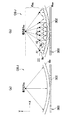
送受信制御部120は、音速測定領域決定部702により決定された音速測定領域119内に、超音波ビームB(図10参照)の送信焦点125を複数設定する。送信焦点125は、局所音速値算出部121による局所音速算出において格子点XROI、格子点A1、格子点A2、・・・となる点である(図11参照)。本実施形態では、送信焦点125は略格子状に設定される。
[RF data acquisition processing for sound velocity measurement]
The transmission /
次いで、図10に示すように、送受信制御部120は、各送信焦点125にそれぞれ送信フォーカスを行うための送信遅延パターンと、各送信焦点125からの超音波エコーを抽出するための受信遅延パターンを選択する。そして、送受信制御部120は、選択した各送信遅延パターン及び各受信遅延パターンに従って、送受信部400に制御信号を出力して超音波の送受信制御を行う。これにより、各送信焦点125に超音波ビームの焦点を合わせつつ、各送信焦点125からの超音波エコーを各素子302で検出することで、各送信焦点125のRF信号が形成される。なお、本実施形態では、図中の各直線Lsに示すように、超音波ビームの焦点をY方向(被検体OBJの深さ方向)に変えながら1ラインずつ各送信焦点125のRF信号を形成する。各送信焦点125のRF信号は、A/D変換器406によりRFデータ(音速測定用の受信データ)に変換された後、シネメモリ602に格納される。
Next, as illustrated in FIG. 10, the transmission /
〔音速測定領域内の局所音速値の算出処理〕
局所音速値算出部121は、特許文献1に開示されたホイヘンスの原理を利用した局所音速算出法を用いて、着目領域112内の個々の領域の局所音速値を求める。
[Calculation process of local sound velocity value in the sound velocity measurement area]
The local sound speed
図11(a),(b)は、局所音速値の算出処理を模式的に示す図である。被検体OBJ内の着目領域を代表する格子点をXROI、格子点XROIよりも浅い(即ち、超音波探触子300側の)位置にXY方向に等間隔で配置された格子点をA1,A2,…とし、少なくとも格子点XROIと各格子点A1,A2,…との間の領域RXAの音速はそれぞれ一定と仮定する。
FIGS. 11A and 11B are diagrams schematically illustrating the calculation process of the local sound speed value. A grid point representing the region of interest in the subject OBJ is X ROI , and a grid point arranged at equal intervals in the XY direction at a position shallower than the grid point X ROI (that is, on the
本実施形態では、格子点A1,A2,…からの受信波(それぞれWA1,WA2,…)の(T及び遅延時間ΔT)が既知として、格子点XROIと格子点A1,A2,…の位置関係から格子点XROIにおける局所音速値を求める。具体的には、ホイヘンスの原理により、格子点XROIからの受信波WXと格子点A1,A2,…からの受信波を仮想的に合成した受信波WSUMが一致することを利用する。 In the present embodiment, the lattice points A1, A2, (W A1, respectively, W A2, ...) ... received wave from as (T and delay time [Delta] T) is known, the lattice point X ROI and grid points A1, A2, ... The local sound velocity value at the lattice point X ROI is obtained from the positional relationship of. Specifically, the principle of Huygens, received wave W X and the lattice point from the lattice point X ROI A1, A2, utilize the received wave W SUM obtained by synthesizing the received waves from ... virtually coincide.
格子点XROI及び格子点A1,A2,…の位置は、上述の送信焦点125の位置に基づき定められる。例えば、図10に示した各送信焦点125の配列において、図中の下から2行目の送信焦点125の1つを格子点XROIと定めた場合に、図中の下から1行目の送信焦点125の中から格子点A1,A2,…が定められる。また、図中の下から3行目の送信焦点125の1つを格子点XROIと定めた場合に、図中の下から2行目の送信焦点125の中から格子点A1,A2,…が定められる。そして、各格子点XROI,A1,A2,…(送信焦点125)について予め取得されてシネメモリ602に格納されているRFデータに基づき局所音速値の算出が行われる。
The positions of the lattice point XROI and the lattice points A1, A2,... Are determined based on the position of the transmission
ここで、格子点XROIにおける局所音速値を求めるときの演算に使用する格子点A1,A2,…の範囲及び個数は予め決めておく。なお、局所音速値演算に使用する格子点の範囲が広いと局所音速値の誤差が大きくなり、狭いと仮想受信波との誤差が大きくなるため、格子点の範囲はこれらの兼ね合いで決める。 Here, the lattice points used in the calculation of the time for obtaining the local sound speed value at the lattice point X ROI A1, A2, ... scope and number of determined in advance. If the range of the lattice point used for the local sound speed value calculation is wide, the error of the local sound speed value becomes large, and if it is narrow, the error with the virtual received wave becomes large. Therefore, the range of the lattice point is determined based on these factors.
また、格子点A1,A2,…のX方向の間隔は、分解能と処理時間の兼ね合いで決定される。格子点A1,A2,…のX方向の間隔は一例で1mmから1cmである。なお、格子点A1,A2,…の間隔が広い場合には、合成波の演算(後述)が困難になるため、補間によって細かい格子点を生成すればよい。 Further, the interval in the X direction between the lattice points A1, A2,... Is determined by the balance between the resolution and the processing time. An interval in the X direction between the lattice points A1, A2,... Is 1 to 1 cm, for example. If the intervals between the lattice points A1, A2,... Are wide, it is difficult to calculate a composite wave (described later), and fine lattice points may be generated by interpolation.
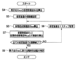
図12に示すフローチャートにおいて、局所音速値算出部121は、上述のように格子点XROI、格子点A1,A2,…の設定を行った後(ステップS1)、各格子点(XROI、A1,A2,…)における最適音速値を判定する(ステップS2)。ここで、最適音速値とは、画像のコントラスト、シャープネスが最も高くなる音速値であり、各格子点における実際の局所音速値とは必ずしも一致しない。ステップS2における最適音速値の判定方法としては、例えば、画像のコントラスト、スキャン方向の空間周波数、分散などから判定する方法(例えば、特開平8−317926号公報)を適用することができる。
In the flowchart shown in FIG. 12, the local sound velocity
次いで、各格子点における最適音速値に基づいて、各格子点における局所音速値の判定が行われる(ステップS3)。以下、最適音速値に基づいて局所音速値を判定する方法を説明する。 Next, based on the optimum sound speed value at each lattice point, the local sound speed value at each lattice point is determined (step S3). Hereinafter, a method for determining the local sound speed value based on the optimum sound speed value will be described.
最初に、図13に示すように、局所音速値算出部121は、格子点XROIにおける最適音速値に基づいて、格子点XROIを反射点とした時の仮想的な受信波(以下、仮想受信波という)WXの波形を算出する(ステップS4)。
First, as shown in FIG. 13, the local sound speed
次いで、局所音速値算出部121は、格子点XROIにおける仮定音速の初期値を設定する(ステップS5)。そして、局所音速値算出部121は、下記のように仮想的な合成受信波(以下、仮想合成受信波という)WSUMを算出する(ステップS6)。格子点XROIにおける局所音速値をVと仮定すると、格子点XROIから伝播した超音波が格子点A1,A2,…に到達するまでの時間はXROIA1/V,XROIA2/V,…となる。ここで、XROIA1,XROIA2,…は、それぞれ格子点A1,A2,…と格子点XROIとの間の距離である。格子点A1,A2,…における最適音速値はステップS2により既知のため、各格子点A1,A2,…からの受信波は予め求めることができる。従って、格子点A1,A2,…からそれぞれ遅延XROIA1/V,XROIA2/V,…で発した反射波(超音波エコー)を合成することにより、仮想合成受信波WSUMを求めることができる。
Next, the local sound speed
なお、実際には、素子データ(RF信号)上で上記処理を行うため、格子点XROIから格子点A1,A2,…に到達するまでの時間(それぞれT1,T2,…)は下記の式(1)により表される。ここで、XA1,XA2,…は、それぞれ格子点A1,A2,…と格子点Xとの間のスキャン方向(X方向)の距離である。また、Δtは格子点のY方向時間間隔である。 Actually, since the above processing is performed on the element data (RF signal), the time (T1, T2,...) From the lattice point XROI to the lattice points A1, A2,. It is represented by (1). Here, X A1 , X A2 ,... Are distances in the scanning direction (X direction) between the lattice points A 1, A 2,. Δt is a time interval in the Y direction of the lattice points.

上記T1,T2,…に、格子点XROIと同一の走査線上の格子点Anから格子点XROIに到達するまでの時間(Δt/2)を足した遅延で各格子点A1,A2,…からの受信波を合成することにより、仮想合成受信波WSUMを求めることができる。 The T1, T2, ..., the time from the lattice point An of the lattice point X ROI and the same scan line until it reaches the lattice point X ROI (Δt / 2) each grid point in the delay plus A1, A2, ... By synthesizing the received wave from, a virtual synthesized received wave WSUM can be obtained.
ここで、格子点をY方向に時間軸で等間隔(Δt)に設定する場合に、空間上での間隔は必ずしも等間隔にはならない。従って、各格子点に超音波が到達するまでの時間を計算するときに、式(1)においてΔt/2の代わりに補正したΔt/2を用いてもよい。ここで、補正したΔt/2は、例えば、格子点XROIと同音線の格子点Anに比べたA1,A2,…の深さ(Y方向の距離)の差をVで除算した値をΔt/2から加算・減算した値である。各格子点A1,A2,…の深さはそれより浅い格子点において局所音速が既知であることから求められる。 Here, when the lattice points are set at equal intervals (Δt) on the time axis in the Y direction, the intervals in space are not necessarily equal. Therefore, when calculating the time until the ultrasonic wave reaches each lattice point, Δt / 2 corrected in Equation (1) instead of Δt / 2 may be used. Here, the corrected Δt / 2 is, for example, a value obtained by dividing the difference in depth (distance in the Y direction) of A1, A2,... Compared with the lattice point X ROI and the lattice point An of the same sound line by V. A value obtained by adding / subtracting from / 2. The depth of each lattice point A1, A2,... Is obtained because the local sound speed is known at a lattice point shallower than that.
また、仮想合成受信波WSUMの算出は、実際に格子点A1,A2,…から遅延XROIA1/V,XROIA2/V,…で発した既定のパルス波(それぞれWA1,WA2,…)を重ね合わせることにより行う。 Further, the virtual composite received wave WSUM is calculated from predetermined pulse waves (W A1 , W A2 , respectively) actually emitted from the lattice points A1, A2,... With delays X ROI A1 / V, X ROI A2 / V ,. , ...) are superimposed.
次に、局所音速値算出部121は、仮想受信波WXと仮想合成受信波WSUMとの誤差を算出する(ステップS7)。仮想受信波WXと仮想合成受信波WSUMとの誤差は、互いの相互相関をとる方法、仮想受信波WXに仮想合成受信波WSUMから得られる遅延を掛けて位相整合加算する方法、又は逆に仮想合成受信波WSUMに仮想受信波WXから得られる遅延を掛けて位相整合加算する方法により算出される。ここで、仮想受信波WXから遅延を得るには、格子点XROIを反射点とし、音速Vで伝播した超音波が各素子302に到着する時刻を遅延とすればよい。また、仮想合成受信波WSUMから遅延を得るには、隣り合う素子302間での合成受信波の位相差から等位相線を抽出し、その等位相線を遅延とするか、又は単に各素子302の合成受信波の最大(ピーク)位置の位相差を遅延としてもよい。また、各素子302からの合成受信波の相互相関ピーク位置を遅延としてもよい。位相整合加算時の誤差は、整合加算後の波形のpeak to peakとする方法、又は包絡線検波した後の振幅の最大値とする方法により求められる。
Next, the local sound velocity
次いで、仮定音速が1ステップ変更された後(ステップS8)、ステップS6からS7が繰り返される。そして、全ての仮定音速の値での演算が終了すると、局所音速値算出部121は、格子点XROIにおける局所音速値を判定する(ステップS9)。ホイヘンスの原理を厳密に適用した場合に、上記のステップS6において求めた仮想合成受信波WSUMの波形は、格子点XROIにおける局所音速値をVと仮定した場合の仮想受信波(反射波)WXの波形と等しくなる。ステップS9では、仮想受信波WXと仮想合成受信波WSUMとの差が最小になる仮定音速の値を格子点XROIにおける局所音速値と判定する。これにより、着目領域112内の1つの格子点XROIにおける局所音速値が求められる。
Next, after the assumed sound speed is changed by one step (step S8), steps S6 to S7 are repeated. Then, when the calculation for all assumed sound speed values is completed, the local sound speed
以下同様にして、局所音速値算出部121は、上述の送信焦点125の位置に基づき定められる着目領域112内の他の複数の格子点XROIの局所音速値を算出する。
Similarly, the local sound speed
<音速マップ生成処理>
図8に戻って、音速マップ生成部122は、局所音速値算出部121が算出した着目領域112内の各格子点XROIの局所音速値に基づき、着目領域112内の局所音速の分布を示す音速マップ130(図16参照)を生成する。
<Sonic velocity map generation processing>
Returning to FIG. 8, the sound speed
<音速マップ更新処理>
更新制御部123は、一定期間経過毎、例えば所定フレーム数(10フレームなど)のBモード画像データの生成が行われる毎に、送受信制御部120、ドプラ信号処理部701、音速測定領域決定部702、局所音速値算出部121、音速マップ生成部122を制御して、音速マップ130の更新処理を行う。具体的には、ドプラモード走査、カラードプラ情報またはCFM像データの生成と、音速測定領域119の決定と、音速測定領域119内のRFデータの取得及び局所音速値の算出と、音速マップ130の生成とが行われる。
<Sonic velocity map update processing>
The
<第1実施形態の超音波診断装置の作用>
次に、図14に示すフローチャートを用いて上記構成の超音波診断装置10の作用について具体的に説明する。単独表示モードでの超音波診断が開始されると、CPU100は、送受信部400に制御信号を出力して、超音波ビームの被検体OBJへの送信、及び被検体OBJからの超音波エコーの受信を開始させる。各素子302で検出された超音波検出信号は送受信部400にてデジタルなRFデータに変換される。
<Operation of Ultrasonic Diagnostic Apparatus of First Embodiment>
Next, the operation of the ultrasonic diagnostic apparatus 10 having the above configuration will be specifically described with reference to the flowchart shown in FIG. When the ultrasound diagnosis in the single display mode is started, the
送受信部400にて生成されたRFデータは、シネメモリ602に格納されるとともに、画像信号生成部500に出力される。そして、画像信号生成部500にてRFデータに基づきBモード画像データが生成されてアナログの画像信号に変換された後に表示制御部105に出力される。この画像信号に基づき、表示制御部105は、表示部104にBモード画像110を表示させる(ステップS10)。
The RF data generated by the transmission /
操作卓202の表示モード切り替えボタンが押下されて、単独表示モードから音速マップ表示モードに切り替えられると(ステップS11)、CPU100は、表示部104に着目領域112の設定を促すメッセージ等を表示させる。医師は、表示部104に表示されるBモード画像110を見ながら、ポインティングデバイス204を操作してBモード画像110上に着目領域112を設定する(ステップS12)。
When the display mode switching button on the
着目領域112の設定がなされると、送受信制御部120は、送受信部400を制御してドプラモード走査に対応した超音波の送受信を各素子302に実行させる。この超音波の送受信により送受信部400にてRFデータが生成され(ステップS13)、このRFデータがドプラ信号処理部701に入力される。なお、ドプラモード走査に対応した超音波の送受信が行われた後は、Bモード走査に対応した超音波の送受信、Bモード画像データの生成・出力が繰り返し実行される。
When the region of
ドプラ信号処理部701は、図3から図5に示したように、ドプラモード走査時に得られたRFデータからカラードプラ情報またはCFM像データを生成する(ステップS14)。このカラードプラ情報またはCFM像データは、音速測定領域決定部702に入力される。
As shown in FIGS. 3 to 5, the Doppler
音速測定領域決定部702は、ドプラ信号処理部701からのカラードプラ情報またはCFM像データに基づき、先に設定された着目領域112の中から移動体領域117を除いた音速測定領域119を決定する(図9(a)〜図9(c)参照、ステップS15)。音速測定領域決定部702の決定結果はCPU100に入力される。
The sound velocity measurement
音速測定領域決定部702からの音速測定領域119の決定結果を受けて、送受信制御部120は、図9及び図10に示したように、音速測定領域119内に送信焦点125を設定した後、送受信部400を制御して超音波の送受信(送信フォーカス、受信フォーカス)を各素子302に実行させる。これにより、各送信焦点125のRFデータが取得(生成・格納)される(ステップS16)。
In response to the determination result of the sound
各送信焦点125のRFデータの取得後、局所音速値算出部121は、図11から図13に示したように、ホイヘンスの原理を利用して、音速測定領域119内の各格子点XROIの局所音速値を算出する。次いで、音速マップ生成部122は、局所音速値算出部121による局所音速値の算出結果に基づき、音速マップ130を生成してDSC504に出力する(ステップS17)。
After acquiring the RF data of each transmission
音速マップ130は、DSC504にてテレビジョン信号の走査方式の画像データに変換され、画像処理部506にて画像処理が施されて画像メモリ508に格納された後、D/A変換器510にてアナログの画像信号に変換されて表示制御部105に出力される。
The sound speed map 130 is converted into image data of a scanning method of a television signal by the
図15に示すように、表示制御部105は、音速マップ130の画像信号と、Bモード走査で得られたBモード画像の画像信号とに基づき、Bモード画像110に音速マップ130を重畳して表示部104に表示させる(ステップS18)。音速マップ130では、音速測定領域119内が局所音速の値に応じて色分けして表示される。
As shown in FIG. 15, the
図14に戻って、ステップS10で説明したように新たなBモード画像データが生成されて画像メモリ508に格納される。先の音速マップ130の生成から一定期間が経過していない場合、具体的には所定フレーム数(10フレームなど)のBモード画像データが生成されていない場合(ステップS19でNO)には、更新制御部123による音速マップ130の更新処理は実行されない。このため、新たに生成されたBモード画像上には、先に生成された音速マップ130が重畳して表示される。
Returning to FIG. 14, as described in step S <b> 10, new B-mode image data is generated and stored in the
一方、先の音速マップ130の生成から一定期間が経過した場合、具体的には所定フレーム数(10フレームなど)のBモード画像データが生成された場合(ステップS19でYES)に、更新制御部123は、音速マップ130の更新処理を実行させる。これにより、上述のステップS13からステップS18までの処理が繰り返し実行される。これにより、新たな音速マップ130がBモード画像110上に重畳表示される。
On the other hand, when a certain period has elapsed since the generation of the previous sound velocity map 130, specifically, when B-mode image data of a predetermined number of frames (such as 10 frames) is generated (YES in step S19), the
以下、音速マップ表示モードが終了(ステップS20でYES)するまで、上述の各処理が繰り返し実行される。 Thereafter, the above-described processes are repeatedly executed until the sound speed map display mode ends (YES in step S20).
なお、図16(a)に示すように、上記第1実施形態では、図中「S」で示した音速測定領域119のRFデータ取得のための超音波の送受信の直前に、図中「D」に示したドプラモード走査に対応した超音波の送受信を行っている。なお、図中「B」は、Bモード走査に対応した超音波の送受信である。この際に、例えば、図16(b)に示すように、ドプラモード走査に対応した超音波の送受信と、音速測定領域119のRFデータ取得のための超音波の送受信との間に、Bモード走査に対応した超音波の送受信を行ってもよい。
Note that, as shown in FIG. 16A, in the first embodiment, “D” in the figure immediately before transmission / reception of ultrasonic waves for acquiring RF data in the sound
<作用効果>
以上のように、本発明では、着目領域112内の音速測定領域119内に送信焦点125を設定し、各送信焦点125に対して超音波の送受信を行って得られたRFデータに基づき音速測定領域119内の局所音速値を求めて音速マップ130を生成しているので、着目領域112内の全領域のRFデータを取得する必要がなくなる。その結果、音速マップ130の生成の際における演算処理を従来よりも低減させることができるので、高性能な演算処理装置(CPU)を用いることなく、音速マップ130の生成並びに表示に要する時間を短縮することができる。さらに、血管(血流)や動きの大きい組織等の各種移動体の影響を受けない音速マップ130を生成することができる。
<Effect>
As described above, in the present invention, the sound velocity measurement is performed based on the RF data obtained by setting the
[第2実施形態の超音波診断装置の構成]
次に、図17を用いて本発明の第2実施形態の超音波診断装置20について説明を行う。上記第1実施形態では、音速測定領域119内に送信焦点125を設定して取得したRFデータに基づき、音速測定領域119内の局所音速値を算出している。これに対して、第2実施形態の超音波診断装置20では、着目領域112内に送信焦点125を設定して取得したRFデータに基づき、音速測定領域119内の局所音速値を算出する。
[Configuration of Ultrasonic Diagnostic Apparatus of Second Embodiment]
Next, the ultrasonic diagnostic apparatus 20 according to the second embodiment of the present invention will be described with reference to FIG. In the first embodiment, the local sound speed value in the sound
なお、超音波診断装置20は、CPU100が第1実施形態とは異なる送受信制御部120a、局所音速値算出部121aとして機能する点を除けば、第1実施形態と基本的に同じ構成であるので、第1実施形態と機能・構成上同一のものについては、同一符号を付してその説明は省略する。
The ultrasonic diagnostic apparatus 20 has basically the same configuration as that of the first embodiment except that the
送受信制御部120aは、着目領域112内の全領域に送信焦点125を設定して超音波の送受信を送受信部400(各素子302)に実行させることで、着目領域112内のRFデータを取得する。また、局所音速値算出部121aは、着目領域112内のRFデータの中から音速測定領域119内の送信焦点125に対応するRFデータを選択して、局所音速値を算出する。
The transmission /
<第2実施形態の超音波診断装置の作用>
図18に示すフローチャート及び図19及び図20に示す説明図を用いて、上記構成の超音波診断装置20の作用について具体的に説明する。なお、音速測定領域119の決定がなされるまでの処理(ステップS10からステップS15まで)は、第1実施形態と同じであるので説明は省略する。
<Operation of Ultrasonic Diagnostic Apparatus of Second Embodiment>
The operation of the ultrasonic diagnostic apparatus 20 configured as described above will be specifically described with reference to the flowchart shown in FIG. 18 and the explanatory diagrams shown in FIGS. Note that the processing (from step S10 to step S15) until the determination of the sound
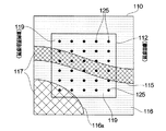
図19に示すように、音速測定領域119の決定後、送受信制御部120aは、着目領域112内の全領域に送信焦点125を設定した後、送受信部400を制御して超音波の送受信(送信フォーカス、受信フォーカス)を実行させる。これにより、着目領域112の全領域内の各送信焦点125のRFデータが取得(生成・格納)される(ステップS21)。なお、本実施形態では、送信焦点125を格子状に設定しているが、送信焦点125の設定パターンは適宜変更してもよい。また、ステップS21は、ステップS13からステップS15の間で適宜実施してもよい。
As shown in FIG. 19, after determining the sound
送信焦点125の設定後、局所音速値算出部121aは、音速測定領域決定部702からCPU100に入力される音速測定領域119の決定結果に基づき、着目領域112内の音速測定領域119を判別する。
After setting the transmission
次いで、図20に示すように、局所音速値算出部121aは、着目領域112内の各送信焦点125に対応するRFデータの中から、音速測定領域119内の送信焦点125(図中、黒丸で表示)に対応するRFデータを選択した後、第1実施形態と同様にして局所音速値を算出する。これにより、音速測定領域119内の局所音速値が得られる。なお、図20中の符号「125’」は音速測定領域119外の送信焦点(図中で白丸で表示)である。音速マップ生成部122は、局所音速値算出部121aによる局所音速値の算出結果に基づき、音速マップ130を生成する(ステップS22)。
Next, as shown in FIG. 20, the local sound velocity
以下、第1実施形態と同様に、音速マップ130がBモード画像110上に重畳表示される。また、先の音速マップ130の生成から一定期間が経過した場合(例えば10フレーム毎)には、上述のステップS13〜S15,S21,S22,S18までの処理が繰り返し実行されることで、音速マップ130が更新される。
Hereinafter, as in the first embodiment, the sound speed map 130 is superimposed and displayed on the B-
超音波診断装置20では、着目領域112の全領域に送信焦点125を設定してRFデータの取得を行うので、音速マップ130の生成のための演算処理や生成時間が増加するものの、血管(血流)等の影響を受けない音速マップ130を生成することができる。
In the ultrasonic diagnostic apparatus 20, the
[その他]
上記各実施形態の局所音速値算出部121,121aは、特許文献1に開示されたホイヘンスの原理を利用した局所音速算出法を用いて音速測定領域119内の局所音速値を求めているが、例えば特許文献1に開示された屈折率モデル計算を利用した局所音速算出法を用いて音速測定領域119内の局所音速値を求めてもよく、局所音速算出法は特に限定はされない。
[Others]
The local sound velocity
上記各実施形態では、着目領域112を矩形状に設定しているが、例えば円形状等の各種形状に着目領域を設定してもよい。
In each of the above embodiments, the region of
上記各実施形態では、所定フレーム数毎(例えば10フレーム)毎に音速マップ130の更新処理を行っているが、例えば先の音速マップ130の生成時から一定時間経過後などの各種一定期間が経過した後に音速マップ130の更新処理を行ってもよい。 In each of the above embodiments, the sound speed map 130 is updated every predetermined number of frames (for example, 10 frames). For example, various fixed periods such as a certain time have elapsed since the previous sound speed map 130 was generated. After that, the sound speed map 130 may be updated.
上記各実施形態では、ドプラ信号処理部701によりカラードプラ情報やCFM像データを生成しているが、ドプラ信号処理部701の構成は、カラードプラ情報やCFM像データを生成可能であれば図3に示した構成に限定されるものではなく適宜変更してもよい。
In each of the above embodiments, the color Doppler information and CFM image data are generated by the Doppler
上記各実施形態では、Bモード走査とドプラモード走査とで各素子302の駆動(超音波の送受信)を異ならせているが、カラードプラ情報やCFM像データを取得可能であれば各素子302の駆動を同じにしてもよい。この場合には、Bモード画像データの生成と、カラードプラ情報やCFM像データの生成とを同時に行うことができる。 In each of the above embodiments, the driving of each element 302 (transmission / reception of ultrasonic waves) is different between B-mode scanning and Doppler mode scanning. However, if color Doppler information and CFM image data can be obtained, The drive may be the same. In this case, generation of B-mode image data and generation of color Doppler information and CFM image data can be performed simultaneously.
10,20…超音波診断装置,100…CPU,110…Bモード画像,112…着目領域,119…音速測定領域,120…送受信制御部,121…局所音速値算出部,122…音速マップ生成部,123…更新制御部,125…送信焦点,130…音速マップ,200…操作入力部,300…超音波探触子,400…送受信部,701…ドプラ信号処理部,702…音速測定領域決定部 DESCRIPTION OF SYMBOLS 10,20 ... Ultrasound diagnostic apparatus, 100 ... CPU, 110 ... B mode image, 112 ... Target area | region, 119 ... Sonic velocity measurement area, 120 ... Transmission / reception control part, 121 ... Local sound speed value calculation part, 122 ... Sonic velocity map generation part , 123 ... Update control unit, 125 ... Transmission focus, 130 ... Sound velocity map, 200 ... Operation input unit, 300 ... Ultrasonic probe, 400 ... Transmission / reception unit, 701 ... Doppler signal processing unit, 702 ... Sound velocity measurement region determination unit
Claims (8)
前記複数の素子をそれぞれ駆動する複数の駆動信号を前記複数の素子に供給し、かつ当該複数の素子から出力された前記超音波検出信号に基づき受信データを生成する送受信部であって、前記複数の素子に供給する前記複数の駆動信号の遅延量を調節することで超音波ビームを形成する送受信部と、
前記被検体内に着目領域を設定する着目領域設定部と、
前記送受信部を制御して、前記着目領域内の移動体の情報を得るための超音波の送受信を前記複数の素子に実行させる第1の送受信制御部と、
前記移動体の情報を得るための超音波の送受信がなされたときに、前記移動体によりドプラ偏移されて反射された超音波の前記超音波検出信号に基づいて前記送受信部が生成した前記受信データから、前記移動体の動きに伴うドプラ信号を抽出して、この抽出結果に基づき前記着目領域内の前記移動体を含む移動体領域を判別する移動体領域判別部と、
前記移動体領域判別部の判別結果に基づき、前記着目領域の中から前記移動体領域を除いた領域を、音速の分布を測定する音速測定領域として決定する音速測定領域決定部と、
前記音速測定領域内に前記超音波ビームの送信焦点を複数設定し、各前記送信焦点に対する前記超音波ビームの送受信を前記送受信部に行わせることで、前記音速測定領域の音速測定用の受信データを前記送受信部に生成させる第2の送受信制御部と、
前記音速測定用の受信データに基づき前記音速測定領域の音速の分布を示す音速マップを生成する音速マップ生成部と、
を備える超音波診断装置。 An ultrasonic probe including a plurality of elements that transmit ultrasonic waves to a subject and receive ultrasonic waves reflected by the subject and output ultrasonic detection signals;
A transmission / reception unit configured to supply a plurality of drive signals for driving the plurality of elements to the plurality of elements and generate reception data based on the ultrasonic detection signals output from the plurality of elements; A transmission / reception unit that forms an ultrasonic beam by adjusting a delay amount of the plurality of drive signals supplied to the element;
A region of interest setting unit for setting a region of interest in the subject;
A first transmission / reception control unit that controls the transmission / reception unit to cause the plurality of elements to perform transmission / reception of ultrasonic waves for obtaining information of a moving body in the region of interest;
The reception generated by the transmission / reception unit based on the ultrasonic detection signal of the ultrasonic wave reflected and reflected by Doppler shift by the mobile body when transmission / reception of ultrasonic waves for obtaining information of the mobile body is performed A moving body region discriminating unit that extracts a Doppler signal accompanying the movement of the moving body from the data and discriminates a moving body region including the moving body in the region of interest based on the extraction result;
Based on the determination result of the mobile body region determination unit, a sound speed measurement region determination unit that determines a region excluding the mobile body region from the region of interest as a sound speed measurement region for measuring the distribution of sound speed;
By setting a plurality of transmission focal points of the ultrasonic beam in the sound velocity measurement region and causing the transmission / reception unit to transmit / receive the ultrasonic beam to / from each transmission focal point, reception data for sound velocity measurement in the sound velocity measurement region A second transmission / reception control unit for generating the transmission / reception unit;
A sound speed map generating unit that generates a sound speed map indicating a sound speed distribution in the sound speed measurement region based on the received data for sound speed measurement;
An ultrasonic diagnostic apparatus comprising:
前記断層像情報を得るための超音波の送受信がなされたときに前記送受信部が生成した前記受信データに基づきBモード画像を生成する画像生成部と、
前記Bモード画像を表示する表示部と、を備え、
前記着目領域設定部は、前記Bモード画像上に前記着目領域を設定する請求項1記載の超音波診断装置。 A third transmission / reception control unit for controlling the transmission / reception unit to cause the plurality of elements to perform transmission / reception of ultrasonic waves for obtaining tomographic image information in the subject;
An image generation unit that generates a B-mode image based on the reception data generated by the transmission / reception unit when ultrasonic transmission / reception for obtaining the tomographic image information is performed;
A display unit for displaying the B-mode image,
The ultrasound diagnostic apparatus according to claim 1, wherein the region of interest setting unit sets the region of interest on the B-mode image.
前記移動体領域判別部は、前記ドプラ信号の抽出結果に基づき、前記着目領域内での前記血液の流れを示す血流情報を生成して、前記血流情報に基づき前記移動体領域を判別する請求項1から4のいずれか1項記載の超音波診断装置。 The moving body includes blood flowing through blood vessels in the region of interest,
The mobile body region determination unit generates blood flow information indicating the blood flow in the region of interest based on the extraction result of the Doppler signal, and determines the mobile body region based on the blood flow information. The ultrasonic diagnostic apparatus of any one of Claim 1 to 4.
前記移動体領域判別部は、前記ドプラ信号の抽出結果に基づき、前記着目領域内での前記組織の移動を示す組織移動情報を生成して、前記組織移動情報に基づき前記移動体領域を判別する請求項1から5のいずれか1項記載の超音波診断装置。 The moving body includes a tissue that moves in the region of interest,
The moving body region determination unit generates tissue movement information indicating movement of the tissue within the region of interest based on the extraction result of the Doppler signal, and determines the moving body region based on the tissue movement information. The ultrasonic diagnostic apparatus of any one of Claim 1 to 5.
Priority Applications (1)
| Application Number | Priority Date | Filing Date | Title |
|---|---|---|---|
| JP2012119579A JP2013244162A (en) | 2012-05-25 | 2012-05-25 | Ultrasonograph |
Applications Claiming Priority (1)
| Application Number | Priority Date | Filing Date | Title |
|---|---|---|---|
| JP2012119579A JP2013244162A (en) | 2012-05-25 | 2012-05-25 | Ultrasonograph |
Publications (1)
| Publication Number | Publication Date |
|---|---|
| JP2013244162A true JP2013244162A (en) | 2013-12-09 |
Family
ID=49844432
Family Applications (1)
| Application Number | Title | Priority Date | Filing Date |
|---|---|---|---|
| JP2012119579A Pending JP2013244162A (en) | 2012-05-25 | 2012-05-25 | Ultrasonograph |
Country Status (1)
| Country | Link |
|---|---|
| JP (1) | JP2013244162A (en) |
Cited By (2)
| Publication number | Priority date | Publication date | Assignee | Title |
|---|---|---|---|---|
| WO2019026115A1 (en) * | 2017-07-31 | 2019-02-07 | 本多電子株式会社 | Ultrasonic image display device and method, and recording medium having program stored therein |
| US20210038195A1 (en) * | 2018-04-28 | 2021-02-11 | Shenzhen Mindray Bio-Medical Electronics Co., Ltd. | Ultrasound transient elasticity measurement device and method |
-
2012
- 2012-05-25 JP JP2012119579A patent/JP2013244162A/en active Pending
Cited By (3)
| Publication number | Priority date | Publication date | Assignee | Title |
|---|---|---|---|---|
| WO2019026115A1 (en) * | 2017-07-31 | 2019-02-07 | 本多電子株式会社 | Ultrasonic image display device and method, and recording medium having program stored therein |
| JP6484781B1 (en) * | 2017-07-31 | 2019-03-20 | 本多電子株式会社 | Ultrasonic image display device |
| US20210038195A1 (en) * | 2018-04-28 | 2021-02-11 | Shenzhen Mindray Bio-Medical Electronics Co., Ltd. | Ultrasound transient elasticity measurement device and method |
Similar Documents
| Publication | Publication Date | Title |
|---|---|---|
| JP5597734B2 (en) | Ultrasonic imaging apparatus and ultrasonic imaging program | |
| JP5389722B2 (en) | Ultrasonic diagnostic apparatus and method for operating the same | |
| JP5808325B2 (en) | Ultrasonic diagnostic apparatus and method of operating ultrasonic diagnostic apparatus | |
| JP6288996B2 (en) | Ultrasonic diagnostic apparatus and ultrasonic imaging program | |
| JP2008168016A (en) | Ultrasonic diagnostic apparatus, imt measurement method, and imt measurement program | |
| WO2012002420A1 (en) | Ultrasound diagnostic device and ultrasound diagnostic method | |
| JP2012217611A (en) | Ultrasonic diagnostic apparatus and method for generating ultrasonic image | |
| JP2007044499A (en) | Ultrasonic diagnostic apparatus and ultrasonic image processing program | |
| JP5623160B2 (en) | Ultrasonic diagnostic apparatus and method for operating the same | |
| US9223011B2 (en) | Ultrasonic signal processing device and ultrasonic signal processing method | |
| JP6687336B2 (en) | Ultrasonic diagnostic device and control program | |
| JP5623157B2 (en) | Ultrasonic diagnostic apparatus and method for operating the same | |
| JP5588924B2 (en) | Ultrasonic diagnostic equipment | |
| JP2011072566A (en) | Ultrasound diagnostic apparatus and signal processing method thereof | |
| JP2010234013A (en) | Ultrasonic diagnostic apparatus and ultrasonic diagnostic method | |
| WO2013176112A1 (en) | Ultrasonic image generating method and ultrasonic image diagnostic device | |
| JP5247330B2 (en) | Ultrasonic signal processing apparatus and ultrasonic signal processing method | |
| JP2013244162A (en) | Ultrasonograph | |
| JP2008142130A (en) | Ultrasonic diagnostic apparatus and its control processing program | |
| JP5851345B2 (en) | Ultrasonic diagnostic apparatus and data processing method | |
| JP2013244159A (en) | Ultrasonic diagnostic equipment and method for estimating sound velocity | |
| JP2012071037A (en) | Ultrasonic image diagnostic apparatus, ultrasonic image forming method, and program | |
| JP2010124852A (en) | Ultrasonic diagnostic device | |
| WO2013073514A1 (en) | Ultrasonic diagnosis device and method | |
| JP2013244161A (en) | Ultrasonograph |