JP2013242811A - Information processing apparatus, and abnormality processing method - Google Patents
Information processing apparatus, and abnormality processing method Download PDFInfo
- Publication number
- JP2013242811A JP2013242811A JP2012116991A JP2012116991A JP2013242811A JP 2013242811 A JP2013242811 A JP 2013242811A JP 2012116991 A JP2012116991 A JP 2012116991A JP 2012116991 A JP2012116991 A JP 2012116991A JP 2013242811 A JP2013242811 A JP 2013242811A
- Authority
- JP
- Japan
- Prior art keywords
- information processing
- abnormality
- unit
- control unit
- processing unit
- Prior art date
- Legal status (The legal status is an assumption and is not a legal conclusion. Google has not performed a legal analysis and makes no representation as to the accuracy of the status listed.)
- Pending
Links
Images


Abstract
Description
本発明は、ソフトウェアの暴走を検出することが可能な複数の情報処理部を有する情報処理装置に関する。 The present invention relates to an information processing apparatus having a plurality of information processing units capable of detecting software runaway.
最近の画像形成装置においては、1つの機器に複数のCPUが搭載され、各CPUが制御対象の各機能を他のCPUと協調しながら制御することで機器全体の性能の向上を図るマルチプロセッサ技術が採用されている。各CPUは、それぞれ特定の処理を受け持ち、統合管理用のCPUとデータ通信することで全体的な制御構成が実現されている(例えば、特許文献1参照。)。 In recent image forming apparatuses, a multi-processor technology in which a plurality of CPUs are mounted on one device, and each CPU controls each function to be controlled in cooperation with another CPU, thereby improving the performance of the entire device. Is adopted. Each CPU is responsible for specific processing, and an overall control configuration is realized by data communication with the CPU for integrated management (see, for example, Patent Document 1).
特許文献1には、複数のプロセッサが管理プロセッサによって管理され、バス制御装置によって共有メモリへのアクセスが制御されるマルチプロセッサシステムに関して、あるプロセッサで障害が発生したとき、障害発生に至るまでの全プロセッサの連携動作を記録しておくマルチプロセッサが開示されている。 Patent Document 1 discloses a multiprocessor system in which a plurality of processors are managed by a management processor, and access to the shared memory is controlled by a bus control device. A multiprocessor for recording the cooperative operation of processors is disclosed.
そして、特許文献1では、不具合に対応するため障害時の情報を記憶しておくために、各プロセッサは、障害を検出した時、自己の走行履歴情報の収集を停止すると共に他のプロセッサへ障害検出を通知する。各プロセッサは、自己の走行履歴情報の収集を停止した後、走行履歴情報を共有メモリ以外に設けた不揮発性メモリに格納する。 And in patent document 1, in order to memorize | store the information at the time of a failure in order to cope with a malfunction, when each processor detects a failure, it stops collection of its own travel history information, and other processors are troubled. Notify detection. Each processor stops collecting its own travel history information, and then stores the travel history information in a non-volatile memory provided in addition to the shared memory.
しかしながら、複数のCPUを搭載した機器では、CPUの数が増える分、不具合が生じる頻度が高くなるおそれがある。一般的なCPUにはソフトウェアの暴走を監視するためにウォッチドッグタイマなどの監視機能が搭載されており、ソフトウェアの暴走時にはCPUを自動的にリセットすることで、復帰させることができる。しかし、複数のCPUが搭載された画像形成装置において、CPUのいずれか1つに不具合が検出された場合に、不具合が検出されたCPUだけをリセットしてもそのままでは印刷を再開することは困難である。 However, in a device equipped with a plurality of CPUs, there is a possibility that the frequency of occurrence of defects increases as the number of CPUs increases. A general CPU is equipped with a monitoring function such as a watchdog timer in order to monitor software runaway, and can be restored by automatically resetting the CPU during software runaway. However, in an image forming apparatus equipped with a plurality of CPUs, if a failure is detected in any one of the CPUs, it is difficult to resume printing without resetting only the CPU in which the failure is detected. It is.
例えば、CPU1が紙送りを制御し、別のCPU2が定着装置を制御している場合において、CPU1の不具合が検出された場合に、CPU2は定着装置を止めるべきなのか定着工程を継続すべきなのかを判断できない。定着装置は高温になるため、CPU2には不具合がなくても一般には定着装置を停止させることが好ましい。よって、システムの全体をリセットした後で、正常であることが確認された後に、画像形成装置は最初から印刷を再開する。このように各CPUをリセットすると、復帰するまでの間、システム全体がダウンしてしまい、何も動作させることが出来ないという問題がある。 For example, when the CPU 1 controls the paper feed and the other CPU 2 controls the fixing device, when a malfunction of the CPU 1 is detected, the CPU 2 should continue the fixing process to stop the fixing device. I can't judge. Since the fixing device is at a high temperature, it is generally preferable to stop the fixing device even if there is no problem with the CPU 2. Therefore, after confirming that the system is normal after resetting the entire system, the image forming apparatus restarts printing from the beginning. If each CPU is reset in this way, there is a problem that the entire system goes down until it returns, and nothing can be operated.
複数のCPUが搭載された場合に、不具合の検出されたCPU又はそのCPUが搭載された情報処理部のみをリセットすることで、画像形成装置が印刷を再開するには、不具合が検出されたCPUの状況を他のCPUが把握するなどの制御が必要になる。 In the case where a plurality of CPUs are mounted, the CPU in which the defect is detected in order for the image forming apparatus to resume printing by resetting only the CPU in which the defect is detected or the information processing unit in which the CPU is mounted. It is necessary to control such that other CPUs grasp the situation.
本発明は上記課題に鑑み、複数のCPUのいずれかに異常が検出された場合に、システム全体のダウンタイムを低減できる情報処理装置を提供することを目的とする。 In view of the above problems, an object of the present invention is to provide an information processing apparatus that can reduce downtime of the entire system when an abnormality is detected in any of a plurality of CPUs.
上述した課題を解決し、目的を達成するために、本発明は、複数の情報処理部を備える情報処理装置であって、前記情報処理部は、ソフトウェアを実行するプロセッサと、前記ソフトウェアの異常を検出する検出部と、異常を検出した前記ソフトウェアを再起動する再起動部と、前記ソフトウェアの異常が検出された場合に、他の前記情報処理部へ異常の発生を通知するエラー通知部と、前記ソフトウェアの異常度合いを示す異常判定値を計測するエラー計測部と、前記異常の検出された前記情報処理部において計測された前記異常判定値を取得する判定値取得部と、取得した前記異常判定値と、予め定められたしきい値とを比較することにより、前記異常の検出された前記情報処理部を復旧させるか否かを判定する復旧判定部と、復旧させると判定された場合に、前記異常の発生した前記情報処理部の前記再起動部に前記ソフトウェアを再起動させる旨指示する再起動指示部と、を特徴とする。 In order to solve the above-described problems and achieve the object, the present invention provides an information processing apparatus including a plurality of information processing units, the information processing unit including a processor that executes software and an abnormality of the software. A detection unit that detects, a restart unit that restarts the software that has detected an abnormality, and an error notification unit that notifies the other information processing unit of the occurrence of an abnormality when an abnormality of the software is detected, An error measurement unit that measures an abnormality determination value indicating the degree of abnormality of the software, a determination value acquisition unit that acquires the abnormality determination value measured in the information processing unit in which the abnormality is detected, and the acquired abnormality determination A restoration determination unit that determines whether or not to restore the information processing unit in which the abnormality is detected by comparing a value with a predetermined threshold value; And when it is determined, characterized by a restart instruction unit for instructing that to restart the software to the restart of the information processing unit generated the anomaly.
本発明によれば、複数のCPUのいずれかに異常が検出された場合に、システム全体のダウンタイムを低減することができる。 According to the present invention, when an abnormality is detected in any of a plurality of CPUs, the downtime of the entire system can be reduced.
以下、図面に基づき本発明の情報処理装置を画像形成装置に具体化した実施形態について説明する。なお、情報処理装置としては、画像形成装置以外に、複数のCPUによって駆動するマルチプロセッサ方式の処理装置であれば、コンピュータや、他の装置にも適用することができる。図1は、画像形成装置100の全体構成図の一例を示す。画像形成装置100は、自動原稿送り装置(ARDF)140と、原稿読み取り部130、書き込みユニット120、作像ユニット110、及び、給紙ユニット150を備える。
Hereinafter, an embodiment in which an information processing apparatus of the present invention is embodied in an image forming apparatus will be described with reference to the drawings. In addition to the image forming apparatus, the information processing apparatus can be applied to a computer or other apparatus as long as it is a multiprocessor processing apparatus driven by a plurality of CPUs. FIG. 1 shows an example of an overall configuration diagram of the
ARDF140は、原稿給紙台上に積載された原稿を、ARDFモータで1枚ずつ画像読み取り部130のコンタクトガラス上に搬送し、原稿の画像データを読み取った後にARDFモータが原稿を排紙トレイ上に排出する。なお、1つのARDF140には複数のARDFモータが搭載されている。
The ARDF 140 transports the originals stacked on the original feeder on the contact glass of the
原稿読み取り部130は、原稿を載置するためのコンタクトガラス11と、光学走査系を有し、光学走査系は、露光ランプ41、第1ミラー42、第2ミラー43、第3ミラー44、レンズ45及びフルカラーCCD46を備える。露光ランプ41及び第1ミラー42は、第1キャリッジに装備され、第1キャリッジは、原稿を読み取る際に、スキャナモータによって一定速度で副走査方向に移動する。第2ミラー43及び第3ミラー44は、第2キャリッジに装備され、第2キャリッジは、原稿を読み取る際に、スキャナモータによって第1キャリッジのほぼ1/2の速度で移動する。そして、第1キャリッジ及び第2キャリッジが移動することによって、原稿の画像面が光学的に走査され、読み取られたデータがレンズ45によってフルカラーCCD46の受光面に結像され、光電変換される。
The
次に、フルカラーCCD(又はフルカラーラインCCD)46によって、赤(R)、緑(G)及び青(B)の各色に光電変換された画像データは、不図示の画像処理回路でA/D変換された後に画像処理回路によって各種の画像処理(補正、色変換、画像分離、階調補正等)が施される。 Next, the image data photoelectrically converted to each color of red (R), green (G) and blue (B) by the full color CCD (or full color line CCD) 46 is A / D converted by an image processing circuit (not shown). After that, various image processing (correction, color conversion, image separation, gradation correction, etc.) is performed by the image processing circuit.
ユーザが複写する操作を指示した場合や、画像形成装置100をプリンタとして利用する場合、作像ユニット110が各色毎に感光体ドラム27y、27m、27c、27Kに潜像を形成する。図では、4つの感光体ユニット13(イエロー用の13y、マゼンダ用の13m、シアン用の13c、ブラック用の13K)が、中間転写ベルト14の搬送方向に沿って並設されている。各感光体ユニット13y、13m、13c、13Kには、像担持体であるドラム状の感光体ドラム27y、27m、27c、27Kと、感光体ドラム27y、27m、27c、27Kを帯電させる帯電装置48y、48m、48c、48K、露光装置47y、47m、47c、47K、現像装置16y、16m、16c、16K及びクリーニング装置49y、49m、49c、49Kが設けられている。
When the user instructs a copying operation or when the
露光装置47y、47m、47c、47Kは、例えば、図示の例では感光体ドラム27y、27m、27c、27Kの軸方向(主走査方向)に配置された発光ダイオード(LED)アレイとレンズアレイからなるLED書込み方式にて露光する。露光装置47y、47m、47c、47Kは、各色毎に光電変換された画像データに応じてLEDを発光して感光体ドラム27y、27m、27c、27K上に静電潜像を形成する。現像装置16y、16m、16c、16Kは、現像剤を担持して回転する現像ローラが、感光体ドラム27y、27m、27c、27K上に形成された静電潜像をトナーで可視化することで各色毎にトナー像を形成する。
The
感光体ドラム27y、27m、27c、27Kに形成されたトナー像は、感光体ドラム27y、27m、27c、27Kと中間転写ベルト14とが接する位置(以下、一次転写位置という)で、中間転写ベルト14上に転写される。感光体ドラム27y、27m、27c、27Kには、中間転写ベルト14を介して中間転写ローラ26y、26m、26c、26Kが感光体ユニット13y、13m、13c、13Kと対にそれぞれ対向配置されている。各中間転写ローラ26y、26m、26c、26Kは、中間転写ベルト14の内周面と接触しており、中間転写時に上方向に移動することで中間転写ベルト14を各感光体の表面に接触させる。中間転写ローラ26y、26m、26c、26Kにそれぞれに電圧が印可されることで、感光体ドラム27y、27m、27c、27Kのトナー像が中間転写ベルト14に転写されるための中間転写電界が発生する。中間転写電界の作用により、中間転写ベルト14上にトナー画像が形成される。各色のトナー画像は重畳して転写され、フルカラーのトナー画像が中間転写ベルト14に形成される。
The toner images formed on the
全ての色の作像と転写が終了した時点で、中間転写ベルト14とタイミングを合わせて給紙トレイ22から、給紙ロータが記録紙53を給紙し、二次転写部50で中間転写ベルト14から4色同時に記録紙53へトナー像が二次転写される。
When image formation and transfer of all colors have been completed, the paper feed rotor feeds the
記録紙53は、第1トレイ22a、第2トレイ22b、第3トレイ22c、第4トレイ22d、手差しトレイ、又は、両面ユニットのいずれかから選択される。各給紙トレイ22a〜22dは、内部に収容された記録紙53を一番上のものから順次送り出す給紙ローラ28、給紙ローラ28によって重送されてしまった複数の記録紙53を個々に分離してから搬送路23に送り出す分離ローラ31を有している。これにより、記録紙53は、搬送路23に向けて搬送開始される。この一連の給紙ローラ28は給紙モータにより駆動されている。
The
給紙ユニット150は、搬送路23の途中に適宜設けられた複数の搬送ローラ対29等を備えている。給紙モータにより駆動される搬送ローラ対29は、給紙トレイ22から搬送された記録紙53を後段の搬送ローラ対29、作像ユニット110の給紙路32に向けて送り出す。給紙路32に送り込まれた記録紙53は、その先端がレジストセンサ51によって検出された後、所定時間が経過すると、レジストローラ33に突き当てられて一旦停止する。このレジストローラ33は、レジストモータにより駆動され、挟み込んだ記録紙53を所定のタイミング(副走査有効期間信号(FGATE)に同期して)で二次転ローラ18の位置まで送り込む。所定のタイミングは、中間転写ベルト14の回転によりフルカラーの重ね合わせトナー画像が二次転ローラ18の位置まで搬送されたタイミングである。
The
二次転ローラ18は、斥力ローラ17と対向配置される。画像形成装置100は、印刷時に二次転ローラ18を中間転写ベルト14に当接させる。二次転ローラ18は二次転モータにより二次転モータの外周の速度が中間転写ベルト14の表面速度と同じになるよう制御されている。
The
記録紙53は、中間転写ベルト14から分離器(不図示)により分離された後に、搬送ベルト24によって定着装置19まで搬送され、定着装置19は記録紙53にトナー像を定着させる。片面印刷の場合、定着後の記録紙53は、排紙モータにより駆動される排紙ローラにより排紙トレイ21上に排出される。
The
図1では、電子写真方式で画像を記録紙53に形成する画像形成装置100を例示したが、画像形成方式は、インク滴を吐出して画像を形成するインクジェット方式、昇華型熱転写方式、ドットインパクト方式の画像形成装置でもよい。
Although FIG. 1 illustrates the
図2は、画像形成装置100の制御系のブロック図の一例を示す。画像形成装置100は、コントローラ制御部210とPCIバス280を介して接続された、読み取り制御部230、エンジン制御部220、及び、書き込み制御部240を有する。また、読み取り制御部230、エンジン制御部220及び書き込み制御部240は、それぞれ紙搬送制御部250、定着制御部260、電源制御部300、及び、作像制御部270とローカルバスやシリアルバス(以下、外部バス290という)などを介して接続されている。以下、読み取り制御部230、エンジン制御部220、書き込み制御部240、紙搬送制御部250、定着制御部260、電源制御部300、及び、作像制御部270を単に「制御部」という場合がある。図示する白抜きの両端矢印線は画像データの流れを示し、太い両端矢印線は制御部が互いに通信するための外部バス190を示す。信号線291は、各制御部を直接、接続しており、High又はLowの信号を送受信することを可能にしている。信号線291は必ずしも必要ではない。
FIG. 2 shows an example of a block diagram of a control system of the
コントローラ制御部210は、画像形成動作の設定を受け付け、画像形成のための動作情報(少なくともジョブIDを含む)を生成し他の制御部に送信する。コントローラ制御部210は、主に画像処理を行うASIC、各種の処理動作を制御するCPU、制御用プログラムを固定的に記憶したROM、各種情報を一時的に記憶するRAM、デジタル複写機の動作に用いるパラメータを記憶するNV−RAM等を有する。また、外部機器からLAN等のネットワークを介して情報を送受信するLANインターフェース(不図示)、ユーザーインターフェースとなる操作パネル214を制御する操作部制御部211、処理対象の画像データを格納するHDD212、FAX通信を行うFCU213と接続されている。
The controller control unit 210 receives the setting of the image forming operation, generates operation information for image formation (including at least the job ID), and transmits the operation information to other control units. The controller control unit 210 is mainly used for an ASIC that performs image processing, a CPU that controls various processing operations, a ROM that permanently stores a control program, a RAM that temporarily stores various information, and an operation of a digital copying machine. An NV-RAM or the like for storing parameters to be used is included. In addition, a LAN interface (not shown) that transmits and receives information from an external device via a network such as a LAN, an operation
コントローラ制御部210は、操作部制御部211から、又は、外部機器からLANインターフェースを介して画像形成動作の設定を受け付け、エンジン制御部220に画像処理を要求する。
The controller control unit 210 receives an image forming operation setting from the operation
エンジン制御部220は、読み取り制御部230、書き込み制御部240、紙搬送制御部250、定着制御部260、電源制御部300、及び、作像制御部270の各制御部を制御する。エンジン制御部220は、画像データの転送、ジョブの内容に応じた各制御部への動作要求、進捗管理等を行う。これらの各制御部が情報処理部に相当する。
The engine control unit 220 controls each control unit of the
読み取り制御部230は、ARDF140と接続され、原稿読み取り部130を制御する。ARDF140は、セットされた原稿の定形用紙サイズを検出し、また、用紙サイズの異なる原稿が混載された場合でも自動的に判別する。ARDF140は、原稿の存在を検出し、原稿が存在する間、原稿を原稿読み取り部130へ1枚ずつ自動的に供給する。
The
読み取り制御部230は、原稿読み取り部130を制御して原稿の画像データを生成する。ユーザが読み取り開始を操作部制御部211に指示すると、エンジン制御部220から指示された読み取り制御部230は、露光ランプを点灯させ、原稿読み取り部130に含まれる第1キャリッジと第2キャリッジの位置をコンタクトガラスの左端に移動させる。読み取り制御部230は、第1キャリッジと第2キャリッジが左端に来ると、ARDF140にコンタクトガラスに原稿を1枚供給させる。読み取り制御部230は、コンタクトガラスの原稿を検出すると、第1及び第2キャリッジを移動させながら原稿面を読み取る。読み取った後は、ARDF140に次の原稿を1枚供給させると共に、第1キャリッジと第2キャリッジの位置をコンタクトガラスの左端に移動させ、原稿データの読み取りを繰り返す。
The
読み取り制御部230は、シェーディング補正、MTF補正、ガンマ補正、黒画像生成、カラー画像生成、2値化処理、多値化処理などの基本的な画質処理を行い、エンジン制御部220に出力する。エンジン制御部220は、原稿の読み取りだけのジョブの場合はコントローラ制御部210に画像データを送信する。この場合、コントローラ制御部210は画像データをHDD212に記憶し、必要であればネットワーク経由で指示された宛先に送信する。コピーのジョブの場合、エンジン制御部220は画像データを書き込み制御部240に送信する。
The
書き込み制御部240は、書き込みユニット120を制御する。書き込み制御部240には、読み取り制御部230が読み取った画像データ、コントローラ制御部210がFCU213から取得した画像データ、または、PC(Personal Computer)が送信し、コントローラ制御部210が画像データに変換した画像データが送信される。書き込み制御部240は、画像データに基づいて図示しないレーザダイオードを変調(オン/オフ)し、レーザ光の照射を制御する。レーザ光は、ポリゴンミラーに反射したのちレンズを通過し感光体ドラム27y、27m、27c、27Kに静電潜像を形成する。
The
書き込み制御部240は、レーザ光の画像領域外の両端に配置されたフォトディテクタにより走査の開始と走査の終了を検出する。1対のフォトディテクタは入射されたレーザ光を同期信号に変換する。書き込み制御部240は、対となる同期信号から2つのPD間をレーザ光が走査する時間間隔を測定し、その時間間隔に予め定められた所定数(解像度)のクロックが収まるように画素クロックを生成する。書き込み制御部240は、この画素クロックに同期して、画像データに対応したレーザ駆動データ(オンオフの変調データ)を生成する。これにより、感光体ドラム27y、27m、27c、27K上に静電潜像が形成される。
The
作像制御部270は、作像ユニット110を制御して、カラーのトナー像を中間転写ベルト14に形成する。作像制御部270は、感光体ドラム27y、27m、27c、27Kと中間転写ベルト14の表面速度が等しくなるように両者を回転制御する。Kの静電潜像の先端部が現像装置のK現像器の現像位置に到達すると、K潜像はKのトナーで現像され始め、Kの静電潜像の後端部が現像位置を通過するとKトナー画像が形成される。
The image forming
作像制御部270は、感光体ドラム27y、27m、27c、27Kと中間転写ベルト14とが接触した時に、中間転写ベルト14に所定のバイアス電圧を印加することで、トナー画像を中間転写ベルト14に転写する。感光体ドラム27y、27m、27c、27K上の残留トナーは上記のようにクリーニングされ、感光体ドラム27y、27m、27c、27Kは除電ランプで除電される。
The image forming
作像制御部270は同様にC、M、Yの各トナー画像を中間転写ベルト14に転写するが、その際、各色のトナー画像の位置が一致するように、書き込み制御部240はレーザ光による書き込み開始のタイミングを調整している。
Similarly, the image forming
紙搬送制御部250は給紙ユニット150を制御する。紙搬送制御部250は、コントローラ制御部210から指示された給紙トレイ22のソレノイドをオンにして給紙ローラ28を記録紙53に接触させる。また、給紙ローラ28を回転駆動して、記録紙53を搬送路に送り出す。紙搬送制御部250は、搬送路の搬送ローラ対29を回転させ、記録紙の先端をレジストセンサによって検出しレジストローラ33に突き当て一端停止させる。そして、副走査有効期間信号(FGATE)に同期して、レジストローラ33を駆動して二次転ローラ18の位置まで送り込む。
The paper
紙搬送制御部250は、レジストローラ33を駆動する前後に二次転ローラ18を中間転写ベルト14に当接させる。紙搬送制御部250は、二次転ローラ18の表面速度が中間転写ベルト14の表面速度と同じになるよう制御する。
The paper
定着制御部260は定着装置19を制御する。定着制御部260は、エンジン制御部220から指示されると、予め定められた温度に定着ヒータの温度を制御する。定着部の動作時には、常に定着部が所望の温度になるよう調節する。定着ヒータは、定着部を加熱する加熱手段であり、定着部は、トナーを転写紙に加圧して定着させる。
The fixing
なお、電源制御部300は、商用電源や自家発電機から供給される交流電源310を直流に整流し、DCDCコンバータで所定の電圧に降圧して各制御部等に供給する。電源制御部300は、コントローラ制御部210からの指示等により電源をオフにすることで消費電力の低減を可能にしている。
The power
各制御部はほぼ共通の構成を有している。図ではエンジン制御部220と紙搬送制御部250により説明するが、他の制御部の構成も同様である。各制御部が固有のICや機能を有していてもよい。
Each control unit has a substantially common configuration. In the figure, the engine control unit 220 and the paper
各制御部は、バスを介して接続されたCPU201、RAM202、ROM203、ソフト監視部204、及び、I/F205を有し、さらに、I/F205に接続された調停回路206、調停回路206に接続された記憶装置207を有する。CPU201は、ROM203に記憶されたプログラムを、RAM202を作業メモリにして実行し各制御部に特有の処理を行う。
Each control unit includes a
I/F205は、調停回路206がCPU201側と外部バス290を接続している場合に、CPU201が他の制御部と通信を行うためのシリアルインターフェースである。ソフト監視部204は、例えばウォッチドッグタイマであり、CPU201が実行するソフトウェアの暴走監視用回路である。ソフト監視部204は、CPU201が実行するソフトウェアの異常(以下、「暴走」とも言う)を検出すると、暴走したCPU201を搭載した制御部のみをリセットする。ソフト監視部204は、暴走回数カウンタ406と、動作時間カウンタ407とを備えている。暴走回数カウンタ406は、ソフトウェアが暴走した累積回数をカウントしており、自動ではリセットされないようになっている。動作時間カウンタ407は、前回のソフトウェアの暴走の後に制御部が復旧してから経過した時間をカウントする。したがって、動作時間カウンタ407は、ソフトウェアの暴走からの復旧時にリセットされる。調停回路206は、外部バス290の通信先を、CPU201、記憶装置207、又は、暴走通知コマンド出力部403のいずれかに切り換える。詳しくは後述する。記憶装置207は、ジョブ実行情報を記憶する不揮発メモリ(NVRAM、EEPROM等)である。
The I /
各制御部のソフト監視部204は信号線291を介して互いに接続されている。ソフト監視部204が自機のCPU201の暴走を検出すると、ダイオード208を介して他の各制御部のCPU201に割り込んで通知する。他の制御部のソフト監視部204が検出したCPU201の暴走はダイオード209(図2参照)を介して、自機のCPU201に割込んで通知される。具体的には、不図示の割り込みコントローラがCPU201への割込みを管理しており、より優先度の低い割込みはマスクされるため、各制御部は復旧処理よりも優先度が低い処理を実行している場合(主に待機状態)にのみ割込みを受け付ける。請求項において述べた検出部、再起動部、エラー通知部、判定値取得部、復旧判定部、再起動指示部、通信遮断指示部、自己診断部、自己診断指示部は、本実施形態においては以上に述べた調停回路を含む各ハードウェアにより実現されているが、ソフト的にこれらの処理を代替することもできる。詳細については後述する。
The
本実施例では、CPU201が暴走した側の制御部は、ソフト的な復旧処理が困難になっている。このため、CPU201が暴走していない他の制御部が、固有の処理を行う通常モードとは異なるプログラムを実行して、暴走したCPU201が搭載された制御部を復旧させる。以下、CPU201が暴走した制御部を「暴走処理中制御部」といい、暴走処理中制御部に対し復旧処理する制御部を「復旧処理中制御部」という。
In the present embodiment, it is difficult for the control unit on the side where the
図3〜6は、ソフトウェアの暴走が起こった制御部の調停回路206の構成図の一例を示す。調停回路206は、スイッチ401、スイッチ404、暴走通知コマンド出力部403及び切替回路402を有する。
3 to 6 show an example of a configuration diagram of the
図3は暴走が検出されない通常時の状態を、図4は暴走が検出された直後の切替回路の状態を、図5は復旧を行う制御部が記憶装置207から異常判定値を読み出す際の状態を、図6は、暴走した制御部が他の制御部へと自己診断処理の結果を通知する際の状態を、それぞれ示す。
3 shows a normal state where no runaway is detected, FIG. 4 shows a state of the switching circuit immediately after the runaway is detected, and FIG. 5 shows a state when the recovery control unit reads the abnormality determination value from the
スイッチ401は、外部バス290の接続先を、I/F205、暴走通知コマンド出力部403、又は、記憶装置207のいずれかに切り換える。また、スイッチ404は、記憶装置207とI/F205、又はソフト監視部204との接続を断接する。このスイッチ404は、ソフトウェアの暴走によりCPU201が記憶装置207へ誤ったデータに書き込みを行わないよう遮断するためのものである。また、ソフト監視部204と記憶装置207とを接続することで、ソフト監視部204でカウントされた各値が記憶装置207へと書き込み可能となる。2つのスイッチ401、404の状態は、切替回路402が制御する。
The
図3に示すように、制御部が起動した直後、切替回路402は外部バス290とI/F205を接続するようにスイッチ401を制御し、記憶装置207とI/F205が接続するようにスイッチ404を制御する。このため、CPU201は、暴走が検出されなければ、記憶装置207及び外部バス290にアクセスできる。
As shown in FIG. 3, immediately after the control unit is activated, the
まず、外部割込みやノイズなどにより、CPU201が暴走した場合、ソフト監視部204のカウンタを定期的にクリアできなくなる。ソフト監視部204はカウンタのオーバフローによりCPU201の暴走を検出する。ソフト監視部204は暴走を検出すると、CPU201にリセット信号を供給する。
First, when the
ソフト監視部204が、リセット信号をアクティブにしている間、暴走したCPU201は停止状態(再起動待ち)となり、切替回路402が復旧コマンドを受信すると、再起動を開始する。復旧コマンドは、復旧処理を行う他の制御部から送信される。
While the
なお、外部割り込みは、センサなどが検出値を通知するためにCPU201に割り込むことである。外部割り込みによるソフトウェアの暴走とは、センサがCPU201に割り込みを通知するポートが割込み側に張り付いたことで、CPU201が割り込み処理に占有されたことを想定している。
Note that the external interrupt is to interrupt the
また、ソフト監視部204はCPU201の暴走を検出すると切替回路402に暴走を検知したことを通知する。図4に示すように、切替回路402は外部バス290と暴走通知コマンド出力部403が接続するようにスイッチ401を制御する。また、切替回路402は、スイッチ404を記憶装置207とソフト監視部204とが接続する状態に制御する。外部バス290と暴走通知コマンド出力部403が接続することで、暴走通知コマンド出力部403は、暴走通知コマンドを各制御部に送信することができる。また、記憶装置207とソフト監視部204とが接続されることで、ソフト監視部204の暴走回数カウンタ406と、動作時間カウンタ407にて、カウントされたそれぞれの値が記憶装置207へと書き込み可能となり、これらの値が書き込まれる。記憶装置207に書き込まれた値は、外部バス290を通じて他の制御部から読み出し可能となる。なお、暴走通知コマンド出力部403は、暴走通知コマンドを、スイッチ401が暴走通知コマンド出力部403と接続している間、継続して発行する。
Further, when the
ここで、暴走通知コマンドは、信号線291と代替可能な機能である。すなわち、各制御部は暴走通知コマンドでなく、信号線291により暴走を通知してもよい。この場合、暴走通知コマンド出力部403は不要なので、図4の状態では外部バス290がI/F205と記憶装置207のどちらとも接続されない状態となる。
Here, the runaway notification command is a function that can replace the
暴走通知コマンドを受信した各制御部は、暴走通知コマンドの優先度と動作中の処理の優先度を比較する。そして、動作中の場合、動作を中断するが復旧処理は行わない。よって、動作中の場合は中断処理を行う。なお、暴走通知コマンドを受信した各制御部は全て中断処理後は待機状態となる。待機状態になるとCPU201が暴走した暴走処理中制御部から通知解除を取得するまで待機状態を継続する。
Each control unit that has received the runaway notification command compares the priority of the runaway notification command with the priority of the process during operation. When the operation is in progress, the operation is interrupted but the recovery process is not performed. Therefore, the interruption process is performed when the operation is in progress. All the control units that have received the runaway notification command are in a standby state after the interruption process. When the standby state is entered, the standby state is continued until the
暴走した制御部から通知を受け取った他の制御部が待機中の場合、制御部は外部バス290に対し暴走通知コマンドを送信した暴走処理中制御部の切替回路402に対し、データ読出コマンドを発行する。データ読出コマンドを最も早く発行した制御部が復旧のための処理を実施する。このデータ読み出しコマンドを受信することにより、暴走処理中制御部は図5に示す状態となり、調停回路206の切替回路402が、外部バス290と記憶装置207とが接続されるようにスイッチ401を切り換える。また、この時点で、切替回路402は、スイッチ404を開いて、記憶装置207とソフト監視部204との接続を解除する。スイッチ401の切り替えにより、外部バス290と記憶装置207との接続が解除されるため、暴走通知コマンドは外部バス290に対して出力されなくなる。このため、最初に暴走通知コマンドを受信した復旧処理中制御部以外の他の制御部はデータ読み出しコマンドを出力することはない。この後、復旧処理中制御部は、記憶装置207から異常判定値を読み出す。
When another control unit that has received a notification from the runaway control unit is waiting, the control unit issues a data read command to the
データ読出コマンドを発行した復旧処理中制御部は、暴走処理中制御部の記憶装置207から異常判定値を読み出すことが可能になる。異常判定値とは、暴走処理中制御部を復旧させるか否かを判定するための数値であり、本実施形態においては、暴走回数カウンタ406、及び動作時間カウンタ407にてカウントされた各値が該当する。なお、異常判定値としては、これらの数値の一方のみを復旧のための判断に用いてもよいし、他の異常の度合いを示すパラメータによって代替することも可能である。
The recovery processing control unit that has issued the data read command can read the abnormality determination value from the
復旧処理中制御部は、異常判定用の閾値を予め有しており、暴走処理中制御部から取得した異常判定値と閾値とを比較することにより判定を行う。 The control unit during restoration processing has a threshold value for abnormality determination in advance, and performs determination by comparing the abnormality determination value acquired from the control unit during runaway processing with the threshold value.
復旧処理中制御部によって復旧が可能と判定された場合は、復旧処理中制御部は暴走処理中制御部に対して、復旧コマンドを発行する。復旧コマンドを受信した暴走処理中制御部は、図3の状態に戻り、暴走処理中制御部の調停回路206の切替回路402は、外部バス290とI/F205が接続されるように、スイッチ401を切り換える。また、切替回路402は、記憶装置207とI/F205が接続されるようにスイッチ404を閉じる。さらに、切替回路402はソフト監視部204に対して、復旧コマンドの受信を通知し、CPU201へのリセットを解除させることで、CPU201の再起動が行われる。
If it is determined by the recovery processing control unit that the recovery is possible, the recovery processing control unit issues a recovery command to the runaway processing control unit. The control unit during the runaway process that has received the recovery command returns to the state of FIG. 3 and the
暴走処理中制御部のCPU201はリセット解除後、ROM203のプログラムを読出し、ジョブ実行情報に基づき動作の再設定を実施する。例えば、I/Oチェックなどを行ってモータ回転速度などの指定に必要なパラメータを設定する。本実施形態では、暴走処理中制御部から読み出したジョブを各制御部が再開する。このように、ジョブ実行情報を記憶装置207から読み出すことにより、暴走状態の前のジョブを再開できる。暴走処理中制御部は、処理中だったジョブの起動を完了したことを他の制御部に通知する。これが暴走通知コマンドの解除通知となり、他の制御部も共に処理を再開する。なお、元々、待機状態であった復旧処理中制御部は、暴走処理中制御部へ復旧コマンドを送信後待機状態へと移行する。元々、待機状態でなければ、復旧処理中制御部は、暴走処理中制御部へ復旧コマンドを送信後、暴走処理中制御部から読み出したソフトウェアのジョブを再開する。
The
一方、判定の結果、暴走処理中制御部に異常が発生しており、復旧させることができないと判定された場合は、復旧コマンドを送信せず、代わりに他の制御部に対して、異常の発生した制御部と連動した処理を実施する制御部を中断状態のまま維持する機能限定モードへの移行を指示するコマンドを出力する。また、復旧処理中制御部は、暴走処理中制御部に対して、自己診断実行コマンドを出力する。自己診断の処理の内容については後述する。 On the other hand, if it is determined that an error has occurred in the control unit during the runaway process and it cannot be recovered as a result of the determination, the recovery command is not sent, and an error is A command for instructing the transition to the function-restricted mode for maintaining the control unit that performs processing linked to the generated control unit in the suspended state is output. In addition, the recovery process control unit outputs a self-diagnosis execution command to the runaway process control unit. The contents of the self-diagnosis process will be described later.
続いて、ソフトウェアの暴走が発生してからの処理の流れを図7のシーケンス図を用いて説明する。図7では、紙搬送制御部250において暴走が検出された場合が示されている。図7に示されるように、まずCPU201にてソフトウェアの暴走が発生すると(ステップS101)、ソフト監視部204において暴走が検出される(ステップS103)。CPU201は、ソフトウェアの暴走が発生した時点で、リセットされ、処理が中止される(ステップS102)。このリセットされた状態は、復旧処理中制御部から復旧コマンドが送信されるまで継続する。
Next, the flow of processing after a software runaway occurs will be described with reference to the sequence diagram of FIG. FIG. 7 shows a case where runaway is detected in the paper
ついで、ソフト監視部204は、暴走が検出されたことにより、暴走回数カウンタ406、及び動作時間カウンタ407の値を更新する(ステップS104)。暴走回数カウンタ406の値は暴走の累積回数の値が1加算される。また、動作時間カウンタ407は、暴走が検出された時点で、カウントがストップされて、その時点の前回の暴走検出から復帰した時点からの連続動作時間が確定する。
Next, the
ついで、ソフト監視部204は、切替回路402に対して、スイッチ401、404を切り替える旨の指示を送る(ステップS105)。指示を受けた切替回路402は、スイッチ401を暴走通知コマンド出力部403が外部バス290と接続されるように切り替える(ステップS106)。また、切替回路402は、スイッチ404を記憶装置207がソフト監視部204と接続されるように切り替える(ステップS107)。この状態となることで、暴走通知コマンド出力部403は、他の暴走が発生していない制御部に対して、暴走通知コマンドを送信することができるようになる(ステップS109)。
Next, the
スイッチ404がソフト監視部204側へと切替されると、ソフト監視部204は、記憶装置207に更新した各カウンタの値を書き込む(ステップS108)。カウンタの値を書き込んだ後は、他の制御部からカウンタのデータの読み出し命令が来るまで待機状態となる。
When the
暴走通知コマンドを受理した他の制御部は、動作中であるか否かを判定する(ステップS110)。暴走通知コマンドを受理した制御部が動作中である場合は(ステップS110:Yes)、処理中の動作の中断処理を行い、待機状態となり、処理を終了する(ステップS111)。一方、暴走通知コマンドを受理した制御部が待機中である場合は(ステップS110:No)、以降この制御部が紙搬送制御部250の復旧処理を行う制御部となり異常判定値となる各カウンタの値を取得するべく紙搬送制御部250へとデータ読み出しコマンドを送信する(ステップS113)。データ読み出しコマンドを受信した紙搬送制御部250の切替回路402は、スイッチ401を記憶装置207側へと切り替える(ステップS114)。また、同じく切替回路402は、スイッチ404を開状態に切替え、ソフト監視部204と記憶装置207の接続を断絶する(ステップS116)。
The other control unit that has received the runaway notification command determines whether or not it is operating (step S110). When the control unit that has received the runaway notification command is operating (step S110: Yes), the processing operation is interrupted, the process enters a standby state, and the process ends (step S111). On the other hand, when the control unit that has received the runaway notification command is on standby (step S110: No), the control unit becomes the control unit that performs the recovery process of the paper
スイッチ401が記憶装置207側へと切り替えられることで、復旧処理中制御部は、各カウンタ値を取得する(ステップS115)。復旧処理中制御部は、取得したカウンタ値のうち、暴走の累積回数の値があらかじめ定められた異常判定用の閾値よりも小さいか否かを判定する(ステップS117)。また、同じく復旧処理中制御部は、取得したカウンタ値のうち、連続正常稼働時間の値が予め定められた異常判定用の閾値よりも長いか否かを判定する(ステップS118)。
When the
暴走の累積回数の値があらかじめ定められた異常判定用の閾値よりも小さい場合(ステップS117:Yes)、又は連続正常稼働時間の値が予め定められた異常判定用の閾値よりも長い場合(ステップS118:Yes)、復旧処理中制御部は、復旧処理を継続し、復旧コマンドを紙搬送制御部250へと送信する(ステップS119)。復旧コマンドを受信した紙搬送制御部250においては、切替回路402は、スイッチ401をI/F205と外部バス290とが接続するよう切り替える(ステップS120)。そして、CPU201は、再起動し(ステップS121)、中断されていた処理の処理途中で停止された時点に復帰処理がなされる(ステップS122)。
When the value of the cumulative number of runaways is smaller than a predetermined abnormality determination threshold (step S117: Yes), or when the continuous normal operation time value is longer than a predetermined abnormality determination threshold (step (S118: Yes), the controller during the recovery process continues the recovery process, and transmits a recovery command to the paper transport control unit 250 (step S119). In the paper
一方、暴走の累積回数の値があらかじめ定められた異常判定用の閾値よりも大きい場合(ステップS117:No)、かつ、連続正常稼働時間の値が予め定められた異常判定用の閾値よりも短い場合(ステップS118:No)、復旧処理中制御部は、紙搬送制御部250への通信遮断を指示する(ステップS123)。そして、復旧処理中制御部は、異常が発生していない他の制御部に対して機能限定モードへの移行を指示し(ステップS124)、自らも機能限定モードに移行し、処理を終了する(ステップS125)。
On the other hand, when the value of the cumulative number of runaways is larger than a predetermined abnormality determination threshold value (step S117: No), the continuous normal operation time value is shorter than the predetermined abnormality determination threshold value. In the case (step S118: No), the control unit during the recovery process instructs the paper
機能限定モードとは、異常が発生した制御部が行う処理を実施しないようにするためのモードである。機能限定モードには、次の3つの種類がある。 The function limited mode is a mode for preventing processing performed by the control unit in which an abnormality has occurred. There are the following three types of function limitation modes.
(i) 機能限定モード:読み取り制御部が動作可能
(ii) 機能限定モード:書き込み制御部、紙搬送制御部、定着制御部及び作像制御部が動
作可能
(iii) 機能限定モード:コントローラ制御部が動作可能
(i)は原稿の読み取りだけが可能で、印刷するための制御部の1つ以上が動作できない状態である。(ii)は読み取り制御部が動作できない状態である。(iii)は読み取りも印刷もできない状態である。
(i) Function-limited mode: Read control unit can operate
(ii) Function-limited mode: Write control unit, paper transport control unit, fixing control unit, and image formation control unit can operate
(iii) Function-limited mode: The controller controller can operate
(i) is a state in which only the original can be read, and one or more control units for printing cannot be operated. (ii) is a state in which the reading control unit cannot operate. (iii) is a state where neither reading nor printing is possible.
各制御部は自己の状態を診断するが、機能限定モードの種類は各制御部から診断結果を取得したコントローラ制御部210が判断する。コントローラ制御部210は動作限定モードの種類に応じて操作パネル214にエラーメッセージを表示したり、ユーザ操作を制限したりする。
Each control unit diagnoses its own state, but the type of the function limited mode is determined by the controller control unit 210 that has obtained the diagnosis result from each control unit. The controller control unit 210 displays an error message on the
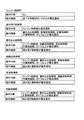
いずれの機能限定モードに移行するか否かの判定には、各制御部が有する、暴走通知コマンドを送信した暴走処理中制御部に応じて、動作を継続するか中断するかを登録した動作決定テーブルを用いる。図8は、動作決定テーブルの一例を示している。 In determining whether to enter any function-restricted mode, each control unit has an operation decision that registers whether to continue or interrupt the operation depending on the control unit during runaway processing that sent the runaway notification command. Use a table. FIG. 8 shows an example of the operation determination table.
動作決定テーブルの一例としては以下のようなものである。なお、「動作中断」とは、制御部の動作が中断されて、機能限定モードへと移行する場合を示しており、「動作継続」とは、制御部に異常が発生した場合であっても、継続して処理が行われる場合を示している。
・エンジン制御部
動作中断:なし(他の制御により動作中断しない)
動作継続:全ての制御部の1つ以上が暴走通知
・読み取り制御部
動作中断:エンジン制御部が暴走通知
動作継続:書き込み制御部、紙搬送制御部、定着制御部、作像制御部の1つ以上が暴走通知
・書き込み制御部
動作中断:エンジン制御部、紙搬送制御部、定着制御部、作像制御部、の1つ以上が暴走通知
動作継続:読み取り制御部が暴走通知
・紙搬送制御部
動作中断:エンジン制御部、書き込み制御部、定着制御部、作像制御部、の1つ以上が暴走通知
動作継続:読み取り制御部が暴走通知
・定着制御部
動作中断:エンジン制御部、書き込み制御部、紙搬送制御部、作像制御部、の1つ以上が暴走通知
動作継続:読み取り制御部が暴走通知
・作像制御部
動作中断:エンジン制御部、書き込み制御部、紙搬送制御部、定着装置、の1つ以上が暴走通知
動作継続:読み取り制御部が暴走通知
An example of the operation determination table is as follows. Note that “operation interruption” indicates a case where the operation of the control unit is interrupted and the mode is shifted to the function limited mode, and “operation continuation” indicates that even when an abnormality occurs in the control unit. This shows a case where the processing is continuously performed.
-Engine control unit operation interruption: None (No operation interruption by other control)
Operation continuation: One or more of all control units runaway notification / reading control unit operation interruption: Engine control unit runaway notification operation continuation: One of writing control unit, paper transport control unit, fixing control unit, image formation control unit The above is the runaway notification / writing control unit operation interruption: one or more of the engine control unit, paper conveyance control unit, fixing control unit, and image formation control unit continues the runaway notification operation: the reading control unit is the runaway notification / paper conveyance control unit Operation interruption: One or more of the engine control unit, write control unit, fixing control unit, and image formation control unit runaway notification operation continuation: Read control unit runs out of control / fixing control unit Operation interruption: engine control unit, write control unit One or more of the paper conveyance control unit and the image formation control unit continue the runaway notification operation: the read control unit performs the runaway notification / image formation control unit operation interruption: the engine control unit, the writing control unit, the paper conveyance control unit, the fixing device One or more of Run the notification operation continued: reading control unit runaway notification
各制御部は、自機の動作決定テーブルを参照して、暴走通知コマンドを受信した場合に動作を中断するか継続するかを判定する。 Each control unit refers to its own operation determination table and determines whether to interrupt or continue the operation when a runaway notification command is received.
また、通信遮断の指示をうけた紙搬送制御部250は、調停回路206が通信の遮断処理を行う(ステップS126)。そして、CPU201は、自己診断処理を行い(ステップS127)、処理を終了する。
Also, in the paper
以下、異常が発生した制御部において行われる自己診断処理の流れについて図9を用いて説明する。図9に示されるように、紙搬送制御部250は、過去の自己診断処理の実行履歴があるか否かを判定する(ステップS201)。過去に自己診断処理の実行履歴がないと判定された場合(ステップS201:No)、制御部は、外部割り込み入力端子を汎用ポートへ変更する(ステップS202)。汎用ポートに変更するのは、割り込みを許可する割り込みポートを利用している場合、CPU201への割り込み信号が入力されることもあるため、正確に接続されたデバイスの入力信号の回数を検出できないためである。次いで、制御部は変更した入力端子への所定の時間内における入力信号の検出回数を測定し、回数を記憶する(ステップS203)。そして、制御部は、検出回数が所定の閾値より小さいか否かを判定する(ステップS204)。
Hereinafter, the flow of the self-diagnosis process performed in the control unit in which an abnormality has occurred will be described with reference to FIG. As shown in FIG. 9, the paper
過去に自己診断処理の実行履歴があると判定された場合(ステップS201:Yes)、その制御部は異常が何度も発生していることから、制御部自体が故障していると判定される(ステップS205)。また、検出回数が所定の閾値より小さい場合も同様に(ステップS204:Yes)、制御部に接続されたデバイスに問題があるのではなく、制御部自体に問題があると判断することができることから制御部自体が故障していると判定される(ステップS205)。制御部が故障している場合については、ステップS126において遮断された状態はそのまま維持される。 When it is determined that there is an execution history of the self-diagnosis process in the past (step S201: Yes), it is determined that the control unit itself is out of order because the control unit has occurred abnormally many times. (Step S205). Similarly, when the number of times of detection is smaller than the predetermined threshold (step S204: Yes), it can be determined that there is a problem with the control unit itself, rather than a problem with the device connected to the control unit. It is determined that the control unit itself has failed (step S205). In the case where the control unit is out of order, the state interrupted in step S126 is maintained as it is.
一方、検出回数が所定の閾値より大きい場合(ステップS204:No)、入力信号が連続して入力され続けていることから、制御部は、汎用ポートに入力信号を送信するデバイスに故障が発生していると判定する(ステップS206)。デバイスとは、例えば制御部ごとに異なっており、例えば用紙の位置を検出するセンサや、駆動用のモータ等である。そして、故障部位の診断が完了後に、制御部は、スイッチ401をI/F205側へと切替え、他の制御部との通信が可能な状態にする(ステップS207)。この際の、制御部の状態が図6に示されている。そして、接続されたデバイスに異常が発生している場合は、制御部自体には異常がないことから、異常が発生している制御部は、他の制御部に対して故障しているデバイスの部位を通知し、自己診断処理を終了する(ステップS208)。この通知を受けたほかの制御部にあっては、上述した機能限定モードを解除するようにしてもよい。
On the other hand, when the number of times of detection is larger than the predetermined threshold (step S204: No), the input signal is continuously input, so the control unit fails in the device that transmits the input signal to the general-purpose port. (Step S206). The device is different for each control unit, for example, a sensor for detecting the position of the paper, a driving motor, or the like. Then, after the diagnosis of the faulty part is completed, the control unit switches the
以上に示した、画像形成装置にあっては、以上のように、本実施例の画像形成装置100は、ある制御部のCPU201が暴走しても、そのCPU201のみをリセットすることで、装置全体を再起動するよりも短時間で復旧することができる。
In the image forming apparatus described above, as described above, the
また、ある制御部において異常が発生した場合であっても、正常に稼動している別の制御部において、発生した異常の度合いを判定し、復旧させるかどうかを決定することができるため、異常が発生しても、必ずしもずっと停止状態とする必要のない場合において、早期に自動的に復旧処理を行うことができるようになる。 In addition, even if an abnormality occurs in a certain control unit, it is possible to determine the degree of the abnormality that has occurred and determine whether to restore it in another control unit that is operating normally. Even if this occurs, the recovery process can be automatically performed automatically at an early stage when it is not always necessary to keep the stop state.
また、機能限定モードを採用することで、待機中の制御部のCPUが暴走した場合には可能な限り他の機能を利用可能とし、動作中の制御部のCPUが暴走した場合には動作を中断することで、確実に保全することができる。 In addition, by adopting the function-limited mode, other functions can be used as much as possible when the CPU of the standby control unit runs out of control, and the operation is performed when the CPU of the operating control unit runs out of control. By suspending, it can be reliably maintained.
また、自己診断処理を行い、異常の発生の原因が、制御部自体にあるのか、他の部材にあるのかを判定することができ、制御部に異常がないことが判定できれば、制御部自体が行う処理については復帰させて実施させることができるようになる。 In addition, self-diagnosis processing can be performed to determine whether the cause of the abnormality is in the control unit itself or in another member, and if it is determined that there is no abnormality in the control unit, the control unit itself The processing to be performed can be restored and executed.
なお、異常判定値は復旧処理中制御部が、暴走処理中制御部から読み取ることにより取得される構成をしたが、暴走処理中制御部が、カウンタの更新後の復旧処理中制御部へと送信することによって同じ機能を実現するようにすることもできる。 Note that the abnormality determination value is acquired by the control unit during recovery processing being read from the control unit during runaway processing, but the control unit during runaway processing sends it to the control unit during recovery processing after updating the counter. By doing so, the same function can be realized.
なお、上記実施の形態では、本発明の画像形成装置を、コピー機能、プリンタ機能、スキャナ機能およびファクシミリ機能のうち少なくとも2つの機能を有する複合機に適用した例を挙げて説明するが、複写機、プリンタ、スキャナ装置、ファクシミリ装置等の画像形成装置であればいずれにも適用することができる。 In the above embodiment, the image forming apparatus according to the present invention is described by taking an example in which the image forming apparatus is applied to a multifunction machine having at least two functions among a copy function, a printer function, a scanner function, and a facsimile function. The present invention can be applied to any image forming apparatus such as a printer, a scanner apparatus, and a facsimile apparatus.
100 画像形成装置
110 作像ユニット
120 書き込みユニット
130 原稿読み取り部
140 ARDF
150 給紙ユニット
201 CPU
202 RAM
203 ROM
204 ソフト監視部
205 I/F
206 調停回路
207 記憶装置
208、209 ダイオード
210 コントローラ制御部
220 エンジン制御部
230 読み取り制御部
240 書き込み制御部
250 紙搬送制御部
260 定着制御部
270 作像制御部
280 PCIバス
290 外部バス
300 電源制御部
401、404 スイッチ
402 切替回路
403 暴走通知コマンド出力部
DESCRIPTION OF
150
202 RAM
203 ROM
204 Software monitoring unit 205 I / F
206
Claims (8)
前記情報処理部は、
ソフトウェアを実行するプロセッサと、
前記ソフトウェアの異常を検出する検出部と、
異常を検出した前記ソフトウェアを実行する前記プロセッサを再起動する再起動部と、
前記ソフトウェアの異常が検出された場合に、他の前記情報処理部へ異常の発生を通知するエラー通知部と、
前記ソフトウェアの異常度合いを示す異常判定値を計測するエラー計測部と、
前記異常の検出された前記情報処理部において計測された前記異常判定値を取得する判定値取得部と、
取得した前記異常判定値と、予め定められたしきい値とを比較することにより、前記異常の検出された前記情報処理部を復旧させるか否かを判定する復旧判定部と、
復旧させると判定された場合に、前記異常の発生した前記情報処理部の前記再起動部に前記プロセッサを再起動させる旨指示する再起動指示部と、
を備えることを特徴とする情報処理装置。 An information processing apparatus including a plurality of information processing units,
The information processing unit
A processor running software;
A detection unit for detecting an abnormality of the software;
A restart unit that restarts the processor that executes the software that has detected an abnormality;
An error notification unit that notifies the other information processing unit of the occurrence of an abnormality when an abnormality of the software is detected;
An error measurement unit that measures an abnormality determination value indicating an abnormality degree of the software;
A determination value acquisition unit that acquires the abnormality determination value measured in the information processing unit in which the abnormality is detected;
A recovery determination unit that determines whether to restore the information processing unit in which the abnormality is detected by comparing the acquired abnormality determination value with a predetermined threshold;
A restart instruction unit that instructs the restart unit of the information processing unit in which the abnormality has occurred to restart the processor when it is determined to be restored;
An information processing apparatus comprising:
を更に備えることを特徴とする請求項1に記載の情報処理装置。 When the restoration determination unit determines not to restore the information processing unit in which the abnormality is detected, the abnormality has occurred with an instruction to block communication between the information processing unit and the other information processing unit The information processing apparatus according to claim 1, further comprising: a communication cutoff instruction unit that sends the information to the information processing unit.
いずれの部位に異常が発生したかの判定を行う自己診断処理を行う自己診断部と、
前記復旧判定部が復旧させないと判定した場合に、前記自己診断処理を前記異常が検出された前記情報処理部の前記自己診断部に実行させる自己診断指示部と、
を更に備えることを特徴とする請求項1に記載の情報処理装置。 The information processing unit
A self-diagnosis unit for performing a self-diagnosis process for determining which part has an abnormality;
A self-diagnosis instruction unit that causes the self-diagnosis unit of the information processing unit in which the abnormality is detected to execute the self-diagnosis process when the recovery determination unit determines not to restore;
The information processing apparatus according to claim 1, further comprising:
ことを特徴とする請求項3に記載の情報処理装置。 The self-diagnosis unit counts the number of detections of a signal input into the information processing unit in which the abnormality is detected within a predetermined time after the start of the self-diagnosis process, and the counted number of detections If the predetermined number of times has been exceeded, it is determined that the device that transmitted the signal has failed. If the number of detections is less than a predetermined number, the information processing unit has failed. The information processing apparatus according to claim 3, wherein a determination is made.
ことを特徴とする請求項4に記載の情報処理装置。 The self-diagnosis unit, when the counted number of times of detection exceeds a predetermined number of times, causes the restarting unit to restart the processor and the information processing unit in which the abnormality has occurred The information processing apparatus according to claim 4, wherein communication with the information processing unit is enabled.
カウントした前記検出回数が予め定められた回数を超えた場合においては、異常がない旨を他の前記情報処理部へと通知する診断結果通知部を、
更に備えることを特徴とする請求項1又は2に記載の情報処理装置。 The self-diagnosis unit
When the counted number of times of detection exceeds a predetermined number of times, a diagnostic result notifying unit that notifies the other information processing unit that there is no abnormality,
The information processing apparatus according to claim 1, further comprising:
更に備えることを特徴とする請求項1又は2に記載の情報処理装置。 When the recovery determination unit determines not to restore the information processing unit, the information processing unit that performs processing in conjunction with the information processing unit in which an abnormality is detected is stopped among the other information processing units. The information processing apparatus according to claim 1, further comprising a stop notification unit that notifies the other information processing unit.
前記情報処理部がソフトウェアの異常を検出する検出ステップと、
前記情報処理部が異常を検出した前記ソフトウェアを実行するプロセッサを再起動する再起動ステップと、
前記ソフトウェアの異常が検出された場合に、前記情報処理部が他の前記情報処理部へ異常の発生を通知するエラー通知ステップと、
前記情報処理部が前記ソフトウェアの異常度合いを示す異常判定値を計測するエラー計測ステップと、
前記異常の発生を通知された他の前記情報処理部が前記異常の検出された前記情報処理部において計測された前記異常判定値を取得する判定値取得ステップと、
前記他の前記情報処理部が、取得した前記異常判定値と、予め定められたしきい値とを比較することにより、前記異常の検出された前記情報処理部を復旧させるか否かを判定する復旧判定ステップと、
前記他の前記情報処理部が、復旧させると判定された場合に、前記異常の発生した前記情報処理部の前記再起動部に前記ソフトウェアを再起動させる旨指示する再起動指示ステップと
を含むことを特徴とする異常処理方法。 An abnormality processing method for an information processing apparatus including a plurality of information processing units,
A detection step in which the information processing unit detects a software abnormality;
A restarting step of restarting a processor that executes the software for which the information processing unit has detected an abnormality;
An error notifying step in which when the software abnormality is detected, the information processing unit notifies the other information processing unit of the occurrence of the abnormality;
An error measurement step in which the information processing unit measures an abnormality determination value indicating the degree of abnormality of the software;
A determination value acquisition step in which the other information processing unit notified of the occurrence of the abnormality acquires the abnormality determination value measured in the information processing unit in which the abnormality is detected;
The other information processing unit determines whether to restore the information processing unit in which the abnormality is detected by comparing the acquired abnormality determination value with a predetermined threshold value. Recovery judgment step;
A restart instruction step that instructs the restart unit of the information processing unit in which the abnormality has occurred to restart the software when it is determined that the other information processing unit is to be restored. An abnormality processing method characterized by the above.
Priority Applications (1)
| Application Number | Priority Date | Filing Date | Title |
|---|---|---|---|
| JP2012116991A JP2013242811A (en) | 2012-05-22 | 2012-05-22 | Information processing apparatus, and abnormality processing method |
Applications Claiming Priority (1)
| Application Number | Priority Date | Filing Date | Title |
|---|---|---|---|
| JP2012116991A JP2013242811A (en) | 2012-05-22 | 2012-05-22 | Information processing apparatus, and abnormality processing method |
Publications (1)
| Publication Number | Publication Date |
|---|---|
| JP2013242811A true JP2013242811A (en) | 2013-12-05 |
Family
ID=49843617
Family Applications (1)
| Application Number | Title | Priority Date | Filing Date |
|---|---|---|---|
| JP2012116991A Pending JP2013242811A (en) | 2012-05-22 | 2012-05-22 | Information processing apparatus, and abnormality processing method |
Country Status (1)
| Country | Link |
|---|---|
| JP (1) | JP2013242811A (en) |
Cited By (3)
| Publication number | Priority date | Publication date | Assignee | Title |
|---|---|---|---|---|
| JP2016091162A (en) * | 2014-10-31 | 2016-05-23 | 株式会社デンソー | Electronic control device |
| JP2016207122A (en) * | 2015-04-28 | 2016-12-08 | 京セラドキュメントソリューションズ株式会社 | Electronic equipment and reboot program |
| US10585755B2 (en) | 2016-11-29 | 2020-03-10 | Ricoh Company, Ltd. | Electronic apparatus and method for restarting a central processing unit (CPU) in response to detecting an abnormality |
-
2012
- 2012-05-22 JP JP2012116991A patent/JP2013242811A/en active Pending
Cited By (3)
| Publication number | Priority date | Publication date | Assignee | Title |
|---|---|---|---|---|
| JP2016091162A (en) * | 2014-10-31 | 2016-05-23 | 株式会社デンソー | Electronic control device |
| JP2016207122A (en) * | 2015-04-28 | 2016-12-08 | 京セラドキュメントソリューションズ株式会社 | Electronic equipment and reboot program |
| US10585755B2 (en) | 2016-11-29 | 2020-03-10 | Ricoh Company, Ltd. | Electronic apparatus and method for restarting a central processing unit (CPU) in response to detecting an abnormality |
Similar Documents
| Publication | Publication Date | Title |
|---|---|---|
| KR100670877B1 (en) | Image forming apparatus and its control method | |
| US7899380B2 (en) | Image forming apparatus having fixing device and controller to execute a cleaning mode | |
| JP2014109719A (en) | Optical writing control device, image forming apparatus and method for controlling optical writing device | |
| JP2013242811A (en) | Information processing apparatus, and abnormality processing method | |
| JP2008256911A (en) | Monitoring system, image forming apparatus and information processor | |
| JP2015203848A (en) | image forming apparatus | |
| US20120293824A1 (en) | Image forming apparatus and sheet jam treatment method for the image forming apparatus | |
| JP2013065019A (en) | Image formation device | |
| JP2019219455A (en) | Image forming apparatus and method for controlling the same | |
| JP5377273B2 (en) | Image forming apparatus | |
| JP2009141526A (en) | Control system, and interruption method | |
| US9665515B2 (en) | Bus arbitration apparatus provided to a bus connected to a plurality of bus masters, bus arbitration method, and computer-readable storage medium | |
| JP2013054314A (en) | Image forming apparatus and operation control method | |
| JP2012247535A (en) | Image forming apparatus | |
| JP5445955B2 (en) | Image forming apparatus | |
| JP4232324B2 (en) | Image forming apparatus | |
| JP2013011677A (en) | Image forming apparatus | |
| JP2011191504A (en) | Image forming apparatus | |
| JP2011128405A (en) | Image forming apparatus | |
| JP4508896B2 (en) | Control system | |
| US9438758B2 (en) | Image forming apparatus | |
| JP2014219562A (en) | Image forming apparatus | |
| JP2005015166A (en) | Image forming device and controlling method thereof | |
| EP2463720B1 (en) | Image forming apparatus, method of controlling image forming apparatus and computer readable information recording medium | |
| JP2013225012A (en) | Image formation control device, image forming apparatus, and control method of image forming apparatus |